

Faber GLORY PRO X/V A 60 LOGIC Instruction Manual
Instructions Manual
Manuel d’Instructions
Bedienungsanleitung
Manual de instrucciones
Руководство по эксплуатации

DE ES RU
INDEX
RECOMMENDATIONS AND SUGGESTIONS......................................................................................................................3
CHARACTERISTICS..............................................................................................................................................................4
INSTALLATION ......................................................................................................................................................................6
USE.......................................................................................................................................................................................11
MAINTENANCE....................................................................................................................................................................12
EN
SOMMAIRE
CONSEILS ET SUGGESTIONS ..........................................................................................................................................16
CARACTERISTIQUES.........................................................................................................................................................17
INSTALLATION ....................................................................................................................................................................19
UTILISATION........................................................................................................................................................................24
ENTRETIEN..........................................................................................................................................................................25
FR
INHALTSVERZEICHNIS
EMPFEHLUNGEN UND HINWEISE....................................................................................................................................29
CHARAKTERISTIKEN..........................................................................................................................................................30
MONTAGE............................................................................................................................................................................32
BEDIENUNG.........................................................................................................................................................................37
WARTUNG............................................................................................................................................................................38
ÍNDICE
CONSEJOS Y SUGERENCIAS ...........................................................................................................................................42
CARACTERÍSTICAS............................................................................................................................................................43
INSTALACIÓN......................................................................................................................................................................45
USO......................................................................................................................................................................................50
MANTENIMIENTO................................................................................................................................................................51
УКАЗАТЕЛЬ
СОВЕТЫ И РЕКОМЕНДАЦИИ...........................................................................................................................................55
ХАРАКТЕРИСТИКИ.............................................................................................................................................................56
УСТАНОВКА........................................................................................................................................................................58
ЭКСПЛУАТАЦИЯ.................................................................................................................................................................63
УХОД ....................................................................................................................................................................................64
2
2

EN
RECOMMENDATIONS AND SUGGESTIONS
The Instructions for Us e a pply t o seve ral versio ns of this appl ianc e. Ac cor
d-
650 mm min.
ingly, you may fin d descriptions of indi vidual features that d o not apply to
your specific appliance.
INSTALLATION
• The manufacturer will not b e held liable for any dam ages resulting fr om incorrect or i mpr op er in sta l lat ion .
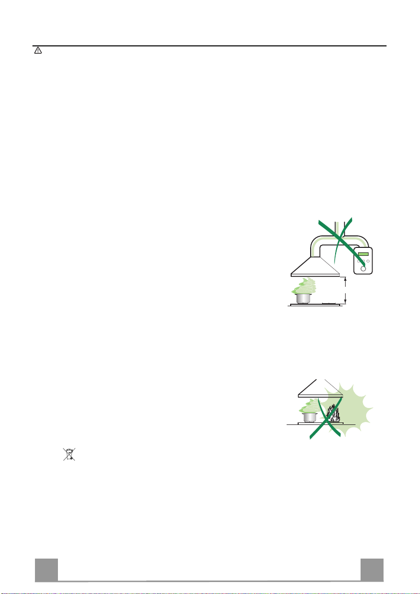
• The minimum safety distance between the cooker top and the extractor
hood is 650 mm (som e m od el s can be installed at a lower height, please refer to the paragraphs on working dimensions and installation).
• Check that the mains voltage corres ponds to that indicated on t he rating
plate fixed to the inside of the hood.
• For Class I appliances, check th at the domestic power supply guarantees
adequate earthing.
Connect the extractor t o the ex haus t flu e throu gh a pipe o f mi nimum diame-
ter 120 mm. The route of the flue must be as short as possible.
• Do not connect the ex tractor hood to exhaust ducts ca rrying combustion
fumes (boilers, fireplaces, etc.).
• If the ext ra ctor is used in conjunction with non-electrical appliances (e. g. g as
burning applia nces), a suffi cient degree of aeration must be guarantee d in
the room in order to prevent t he backfl ow of exha ust gas. T he kitch en must
have an opening communicating directly with the open air in order to
guarantee the entry of clean air.
USE
• The extractor hood has been designed exclusively for domestic use to eliminate kitchen smells.
• Never use the hood for purposes other than for which it has been designed.
• Never leave high naked fla me s un der the ho od wh en it is in oper at i on.
• Adjust th e fl am e i n te nsity to direct it onto the bottom of t he pan only, making
sure that it does not engulf the sides.
• Dee p fat fryers must b e continuously m onitored durin g use: overheate d oil
can burst into flames.
• Do not flambè under the range hood; risk of fire
• This ap pliance is not i ntended for use by persons (includi ng children) with
reduced physical , sensory or mental capabilitie s, or lack of ex perience and
knowledge, unless th ey have been g iven su pervi sion o r in structi on con cern ing use of the appliance by a person responsible for their safety.
• Child re n sh ould be supervised to ensure that they do not play with the appliance.
MAINTENANCE
• Switch off or unplug the appliance from the m ains supply before carrying out
any maintenance work.
• Clean and/or replace the Filters after the specified time period (Fire hazard).
• Clean the hood using a damp cloth and a neutral liquid detergent.
The symbol on the product or on its packaging indicates that this product may not be treated
as household waste. Instead it shall be handed over to the applicable collection point for the
recycling of electrical and electronic equipmen t. By ensuring this pr o duct is disposed of correctly,
you will help prevent potential negative consequences for the environment and human health,
which could otherwise be caused by inappropriate waste handling of this product. For more
detailed information about recycling of this product, please contact your local city office, your
household waste disposal service or the shop where you purchased the product.
3
3

EN
CHARACTERISTICS
2
12c
1
12f
12q
22
15
10
9
25
11
12h
21
23
22
7.1
7.1b
7.1a
12g
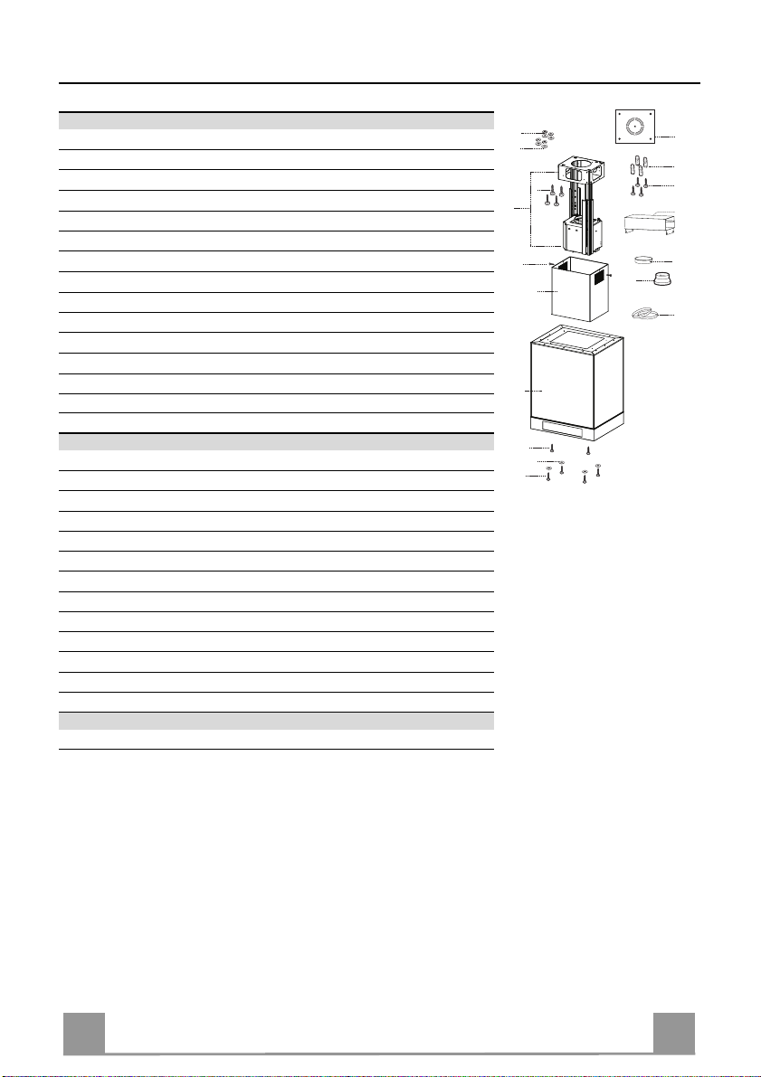
Components
Ref. Q.ty Product Components
1 1 Hood Canopy c omplete with: C ontrols, Light, Filters
2 1 Telescopic chimney, made up of:
2.1 1 Upper chimney
2.2 1 Lower chimney
7.1 1 Telescopic f rame complet e with Suction fan, made up of:
7.1a 1 Upper frame
7.1b 1 Lower frame
9 1 Reduction flange ø 150-120 mm
10 1 Flange ø 150
11 2 Side Glass
12 2 Front Glass
13 4 Glass Fastener Element
15 1 Air Outlet Connector
25 Pipe clamps (not included)
Ref. Q.ty Installation Components
7.1.1 2 Side Glass Brackets
7.1.2 2 Centre Glass Brackets
11 4 Wall plugs ø 10
12c 2 Screws 2.9 x 6. 5
12f 2 Screws M4 x 80
12g 4 Screws M6 x 80
12h 4 Screws 5.2 x 70
12p 10 Screws M4x10
12q 4 Screws 3,5 x 9,5
21 1 Drilling template
22 8 Washers ø 6.4
23 4 Nuts M6
Q.ty Documentation
1 Instruction Manual
4
4
EN
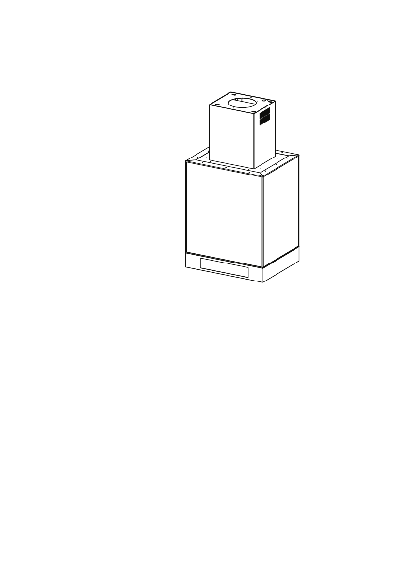
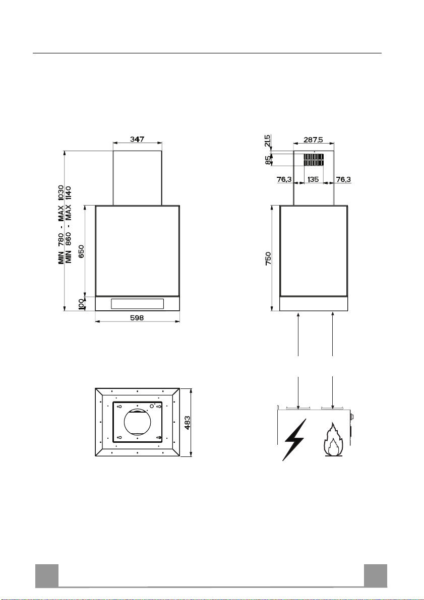
Dimensions
*
**
* Dimensions of the hood in ducting version.
** Dimensions of the hood in recycling version.
Min.
650mm
Min.
650mm
5
5

EN
INSTALLATION
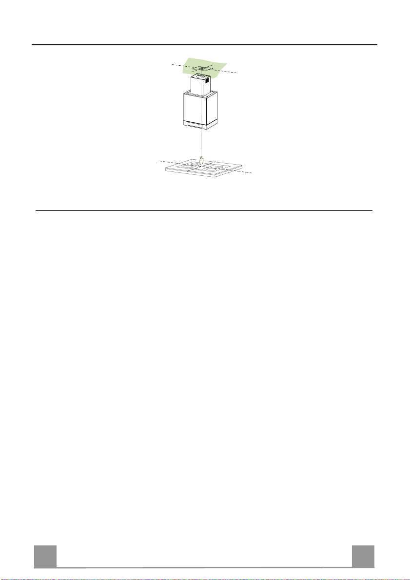
Drilling the Ceiling/shelf and fixing the frame
DRILLING THE CEILING/SHELF
• Use a plumb line to mark the centre of the hob on the ceiling/support shelf.
• Place the drilling template 21 provided on the ceiling/support shelf, making sure that the
template is in the correct position by lining up the axes of the template with those of the hob.
• Mark the centres of the holes in the template.
• Drill the holes at the points marked:
• For concrete ceilings, drill for plugs appropriate to the screw size.
• For hollow brick ceilings with wall thickness of 20 mm: drill ø 10 mm(immediately insert
the Dowels 11 supplied).
• For wooden beam ceilings, drill according to the wood screws used.
• For wooden shelf, drill ø 7 mm.
• For the power supply cable feed, drill ø 10 mm.
• For the air outlet (Ducted Versio n), drill according to t he diameter of the external air exhaust duct connection.
• Insert two screws of the following type, crossing them and leaving 4-5 mm from the ceiling:
• For concrete ceilings, use the appropriate plugs for the screw size (not provided).
• for Cavity ceiling with inner space, with wall thickness of approx. 20 mm, Screws 12h,
supplied.
• For wooden beam ceilings, use 4 wood screws (not provided).
• For wooden shelf, use 4 screws 12g with washers 22 and nuts 23, provided.
6
6
EN
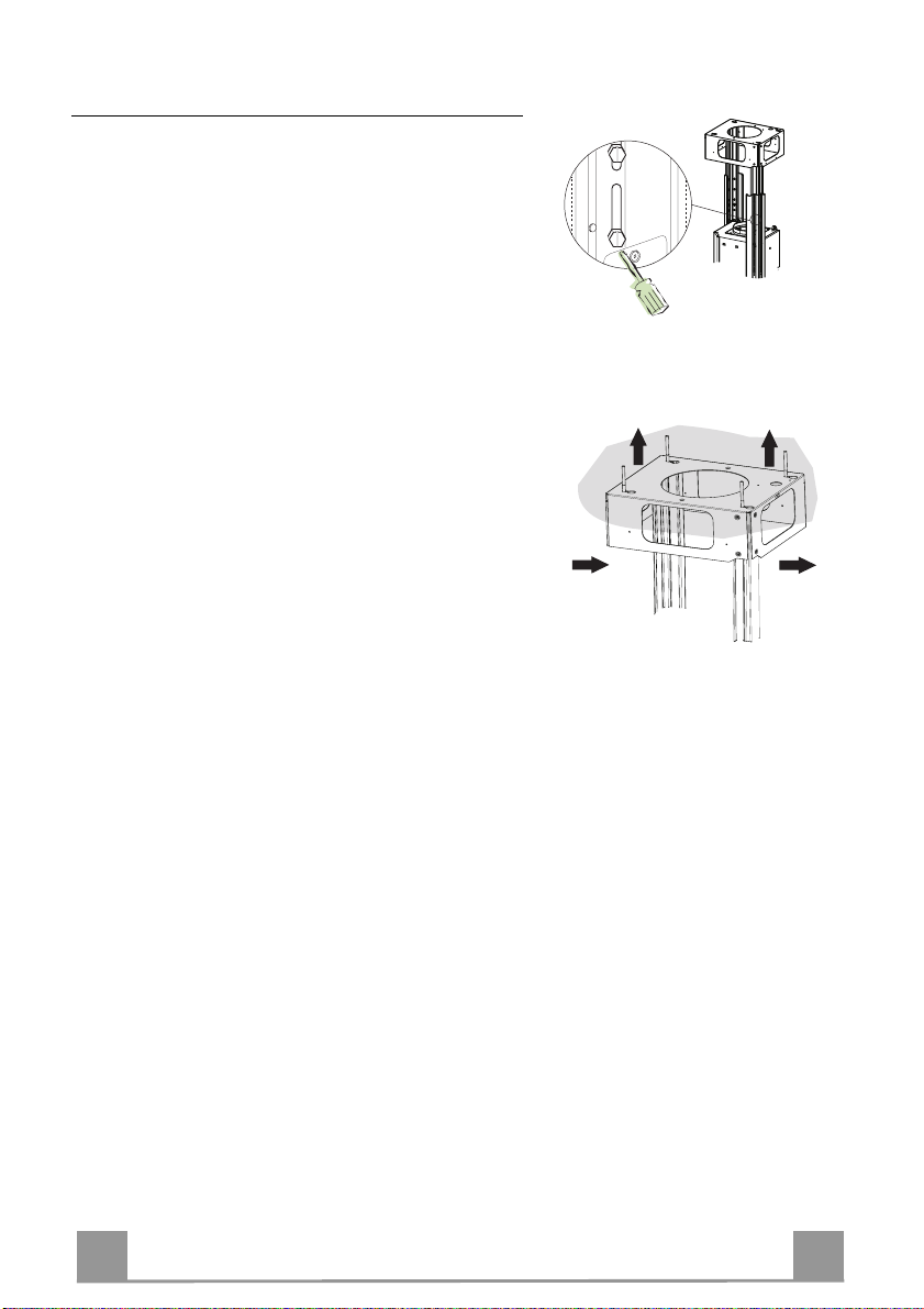
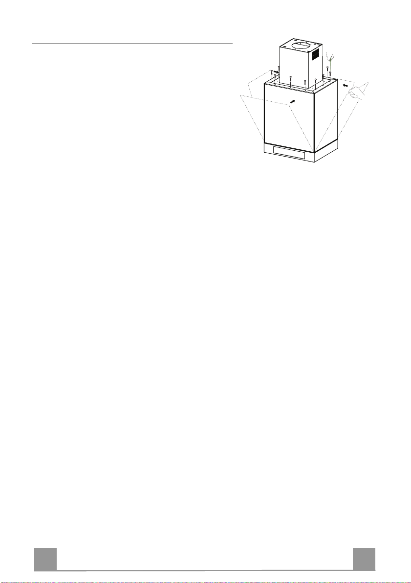
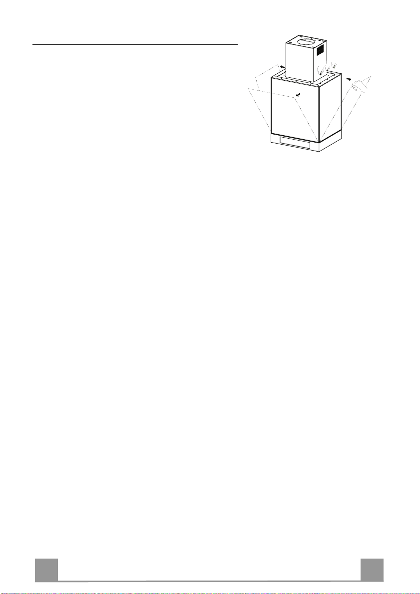
Fixing the Frame
Should it be necessary to adj ust the heigh t of the frame,
proceed as follows:
• Unfasten the two screws fixing the upper chimney,
and remove it from the frame (from the upper part).
• Unfasten the metric screws joining the two columns,
at the sides of the frame;
• Adjust the fra me to the height required, then replace
the screws removed as described above;
• Insert the upper chimney from above and leave it free
on the frame;
• Lift the frame, insert the slots onto the screws and
slide them until they lock;
• Tighten the two screws and insert the other two
screws provided.
Before final locking of the screws it is possible to make
small adjustments to the frame, making sure that the
screws do not come out of the adjustment slot.
• The Frame must be securely fasten ed both due to the
weight of the Hood and the stress caused by occasional sideways pressure on the Appliance when in
position. When fastened , check t hat the base i s stable
even when the Frame is subjected to bending.
• In all cases where the Ceiling is not sufficiently
strong at the point of suspension, the Installation
technician must strength en it with suitable plates and
counterplates, anchored to structurally sound elements.
1
2
1
2
7
7

EN
Ducted version air exhaust system Connection
9
ø 150
ø 120
25
25
15
10
When installing the ducted version, connect the hood to the
chimney using either a flexible or rigid pipe ø 150 or 120 mm,
the choice of which is left to the installer.
• To install a ø 120 mm air exhaust connection, insert the reducer flange 9 on the hood body outlet.
• Fix the pipe using the pipe clamps 25 (not provided).
• Remove any activated ch arcoal filters.
Recirculation version air outlet
• Fix the connection 15 to the frame using the 4 screws provided.
• Fix the flange 10 to the lower opening of the connection 15.
• Connect the hood air outlet to the flange in the lower part of
the junction using a rigid or flexible ø 150 tube (by installer’s
choice).
8
8
EN
Fitting the Chimney and Fixing the Hood Canopy
A
B
12c
22
12f
12q
24
12e
Neon
• Insert the Upper chimney with the slots facing upwards if the
hood is to be installed in the recirculation version, or vice versa
with the slots facing downwards if it is to be installed in the
ducting version, and fix the top part to the Upper Chimney
Connector using the Screws 12c (2.9 x 9.5) provided.
Recirculation version
• Make sure that position of the Air Outlet Connector 15 corresponds to the Chimney Grille.
• If this is not the case, remove the chimney and adjust the position of the Air Outlet Connector 15; replace the elements as
described above.
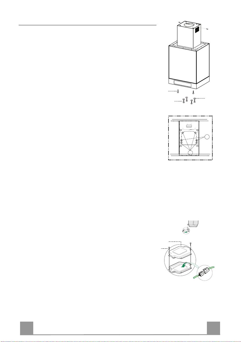
Before fixing the Hood Canopy to the Frame:
• Screw the 2 screws 12f half way into the holes provided in the
sides of the bottom of the frame.
• Open the suction panel by pulling it.
• Unfasten the panel from the hood canopy by sliding the fixing
pin lever provided.
• Remove the Grease filters from the Hood Canopy.
• Remove any Activated charcoal filters.
• Lift the hood canopy and engage the screws 12f in the slots (A)
as far as they will go.
• Working from below, fix the hood canopy to the frame (B),
using the 4 screws 12q and 4 washers 22 provided, then tighten
all the screws securely.
ELECTRICAL CONNECTION
• Connect the Hood to the Mains Power Supply, inserting a
bipolar switch with a cont act aperture of at least 3 mm.
• Open the Suction Panel and the grease filters, make sure that
the power cable is properly inserted into the Suction fan socket
• Hook up the Conn ectors.
• From the inside, open the Neon lamp wiring box 24 by unfas-
tening the Screws.
• Hook up the remaining free Connector to the one in the Neon
lamp wiring box, then close the cover and fit the box in the location provided.
• For the Recirculation Version, fit the Activated Charcoal
Odour Filter.
• Replace the Grease Filters and the Suction Panel.
9
9
EN 110
Fitting Glass Elements
• Fit the Side Glass on the Body (first the bottom then
the top) and fix it in place with the Side Glass
Bracket 7.1.1 using the Screws 12p provided.
• Fit the Glass Fastener Ele ments on the Front Glass,
fit the latter on the Body (first the bottom then the
top) and fix it in place with the Front Glass Bracket
7.1.2 using the Screws 12p provided.
EN 111
USE
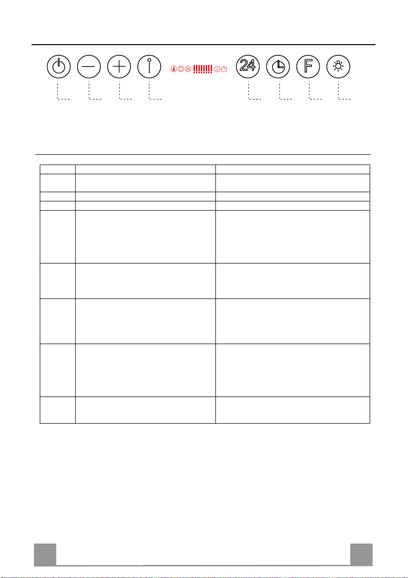
E F G HA B C D
Control panel
Button Function Display
A Turns the suction motor on and off at the
B Decrease the working speed. The number of lighted segments decreas es.
C Increase th e working speed. The number of lighted segments increases.
D Activate intensive speed from any other
E Starts the Motor at a speed that allows
F
G Perform a Reset of the Filter saturation
H Turns the lighting system (Spotli ghts) on
last speed used.
speed, including motor off. This speed is
set to operate for 10 minutes, after which
the system returns to the speed that was set
before. Suitable to deal with maximum
levels of cooking fumes.
suction of 100 m3/ h for 10 minutes ever y
hour, after whic h the Motor will stop.
Activate automatic switch-off with a 30’
delay. Suitable to complete elimination of
residual odours. Can be activated from any
position, and is disabled by pressing the
button or turning the motor off.
alarm when the Button is pressed for approximately 2 seconds.
and off. Turns th e Neon lights on and off
when pressed and held for 2 seconds.
Keyboard Lock: it is possible to lock the keyboard, for example when cleaning the Glass,
when the Hood has Motor and Lights turned off.
Press D (Intensive) for approximately 5 Seconds to enable or disable the Keyboard Lock,
which is always confirmed by a Beep and an animation on the display motor bar.
Displays the set speed.
The indica tor I flas hes and a ll the segmen ts on
the Display are lit.
It is disabled by pressing the Button.
Displays 24 and the segment s on the Display
all light up and then turn off one at a time in
cycle.
It is disabled by pressing the Button.
Displays a flashing Clock symbol.
It is disabled by pressing the Button.
After 100 hours in operation the Drop symbol
is displayed to indicate saturation of the Metal
Grease Filters.
After 200 hours in operation the letter C is
displayed to indicate saturation of the Activated Charcoal filters.
EN 112
MAINTENANCE
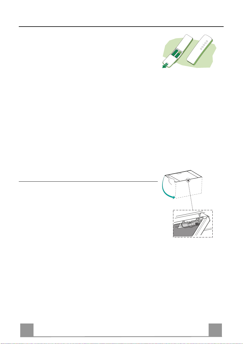
REMOTE CONTROL (OPTIONAL)
The appliance can be controlled using a remote control powered
by a 1.5 V carbon-zinc alkaline batteries of the standard LR03AAA type (not included).
• Do not place the remote co ntrol near to heat sources.
• Used batteries must be disposed of in the proper manner.
Cleaning the Comfort Panels
• Pull the Comfort Panel to open it.
• Disconnect the panel from the hood canopy by sliding the fixing pin lever.
• The comfort panel must never be washed in a dishwasher.
• Clean the outside by using a damp cloth and neutral liquid detergent.
• Clean the inside as well by using a damp cloth and neutral detergent; do not use wet cloths or sponges, or jets of water; do
not use abrasive substances.
• When the above operation has been completed, hook the panel
back to the hood canopy and close it by turning the knob in the
opposite direction.

EN 113
Metal grease filters
Metal filters can be washed also in a dish machine. They need to
be washed every time a drop-symbol appears in the display or at
least every two months. In case of very frequent use these have to
be washed even more often.
Alarm reset
• Press the G-key for at least 2 seconds.
Cleaning
• Open the comfort panel.
• Remove the filters one by one by pushing them backwards and
pulling them down contemporaneously.
• Wash the filters. Pay attention not to bend them. Make sure
that filters are completely dry before putting them into their
seat. (a possible modification of the filter surface doesn’t influence its efficiency).
• Place the filters again into their seats and make sure that the
handle of the filter remains outside.
• Close the comfort panel.
EN 114
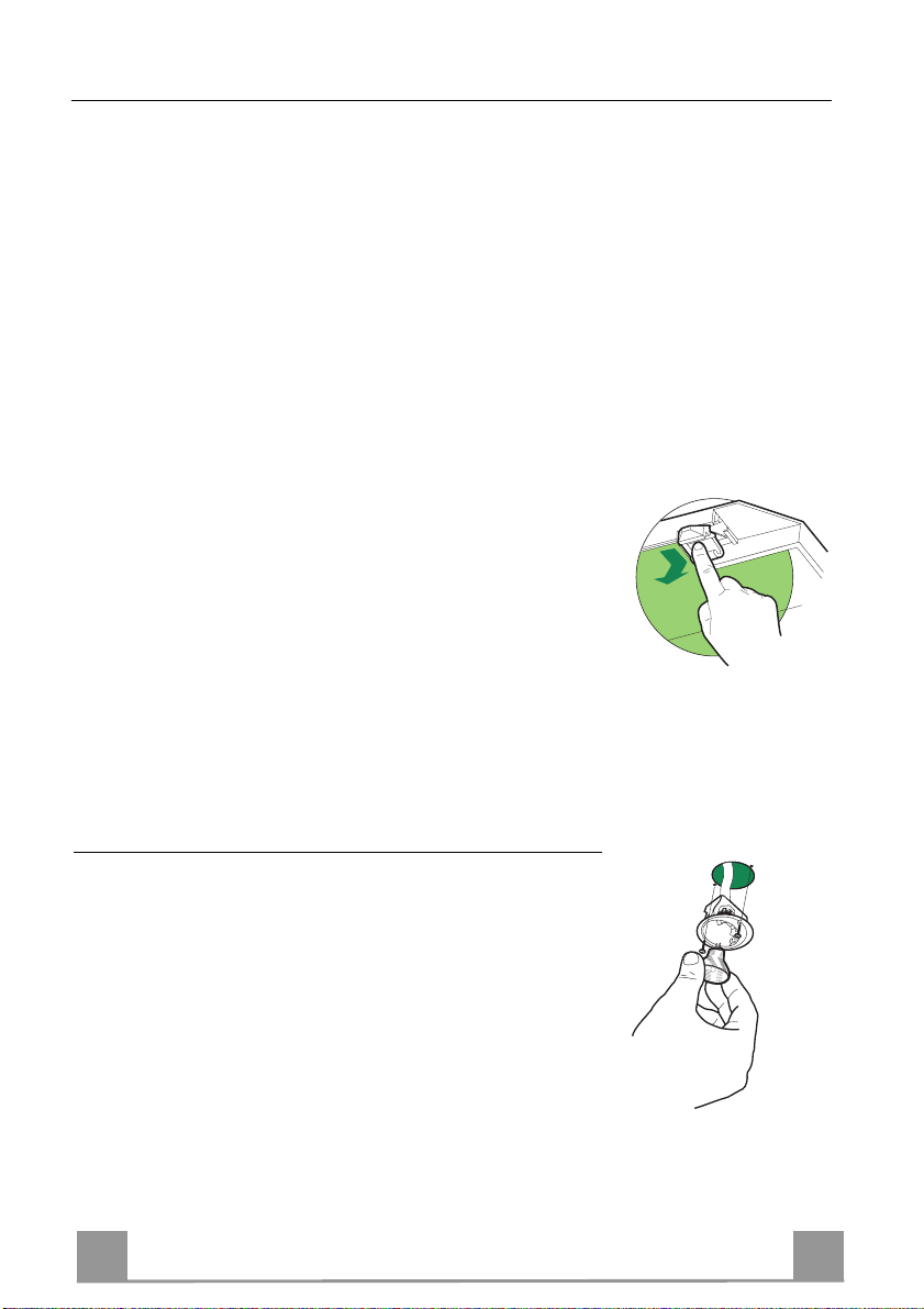
Charcoal filter (recycling version)
This filter cannot be washed or regenerated. It must be replaced when the C appears on the
display or at least once every 4 months. The filter saturation alarm has to be activated already
before.
Activation of the alarm signal
• In the recycling version hoods the filter saturation alarm must be activated during the installation or later.
• Switch off the hood and the lights.
• Press the E-key for about 5 seconds until the last two segments of the motor LEDS are lit on
the display.
• By releasing the E-key the clock icon starts to flash.
• Within 3 seconds press the D-key to activate/ deactivate charcoal filter saturation alarm.
• C-symbol lit - charcoal filter saturation alarm ACTIVATED.
• C-symbol unlit - charcoal filter saturation alarm DEACTIVATED.
SUBSTITUTION OF TH E CHARCOAL FILTER
Alarm reset
• Switch off the motor and the lighting system.
• Press the G-key for at least 2 seconds.
Substitution of the filter
• Open the confort panel.
• Remove the metal grease filters.
• Remove the charcoal filter as indicated in the picture.
• Place the filter again into its seat.
• Place again the metal grease filters into their place.
Lighting
LIGHT REPLACEMENT
20 W halogen light.
• Remove the 2 screws fixing the Lighting support, and pull it
out of from the Hood.
• Extract the lamp from the Support.
• Replace with another of the same type, making sure that the
two pins are properly inserted in the lamp holder socket holes.
• Refit the Support, fixing it in place with the two screws removed as above.
EN 115
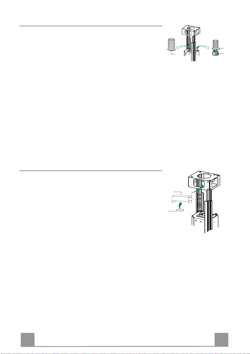
Lighting
CHANGING LAMPS
ATTENTION: When removing the Upper Glass Support
Bracket, hold the Glass with the Hand and be careful not
to drop it.
16 W neon lamps.
• Unfasten the Screw fixing the head of the Vertical
Glass protecting t he Neon lamp to be changed.
• Slide the Glass until the end comes free.
• Re move the lamp and replace it with a new one with
the same characteristics.
• Reassemble by repeat ing the above operation s in reverse order.
N.B. Should it be necessary to change the Starter, follow the same steps giv en above for ch anging the la mp,
then replace the component in the upper part of the
broken Neon lamp.
FR 116
CONSEILS ET SUGGESTIONS
650 mm min.
La présente notice d'emploi vaut pour plusieurs versions de l'appareil. Elle peut conte-
nir des descriptions d'accessoir es ne fi gurant pas dan s votr e apparei l.
INSTALLATION
• Le fabricant décline toute responsabilité en cas de dommage dû à une inst alla tion non
correcte ou non conforme aux règles de l ’ art.
• La distance minimale de sécurité entre le plan de cuisson et la hotte doit être de 650
mm au moins (certains modèles peuvent être installés à une hauteur inférieure : se reporter aux paragraphes « Encombrem ent » et « Instal lati on »).
• Vérifier que la tension du secteur correspond à la valeur qui figure sur la plaquette
apposée à l’intérieur de la hotte.
• Pour les Appareils appartenant à la Ière Classe, veiller à ce que la mise à la terre de
l’installation électrique domestique ait été effectuée conformément aux normes en vigueur.
• Connecter la hotte à la sort ie d’air aspiré à l’ aide d’une tuyauterie d’un diamètre égal ou
supérieur à 120 mm. Le parcours de la tuyaut eri e doit être le plus court possibl e.
• Ne pas connecter la hotte à des conduites d’évacuation de fumées issues d’une combustion tel que (Chaudière, chemi née, et c…).
• Si vous utilisez des appareils qui ne fonctionnent pas à l’électricité dans la pièce ou est
installée la hotte (par exemple: des appareils fonctionnant au gaz), vous devez prévoir
une aération suffisante du milieu. Si la cuisine en est dépourvue, pratiquez une ouverture qui communique avec l’ext érieur pour garant ir l’infil trati on de l’ai r pur.
UTILISATION
• La hotte a été conçue exclusivement pour l’usage domestique, dans le but d’éliminer
les odeurs de la cuisine.
• Ne jamais utiliser abusivement la hotte.
• Ne pas laisser les flammes libres à forte intensité quand la hotte est en service.
• Toujours régler les flammes de manière à éviter toute sortie latérale de ces dernières
par rapport au fond des marmites.
• Contrôler les friteuses lors de l’utilisati on car l’huile sur chauff ée pourrai t s’ enfl ammer.
• Ne pas préparer d’aliments flambés sous la hotte de cuisi ne : risque d’ incendi e
• Cet appareil ne doit pas être utilisé par des personnes (y compris les enfants) ayant
des capacités psychiques, sensorielles ou mentales réduites, ni par des personnes
n’ayant pas l’expérience et la connaissance de ce type d’appareils, à moins d'être sous
le contrôle et la formation de personn es respo nsables de l eur sécuri té.
• Les enfants doivent être surveillés pour s'assurer qu'ils ne jouent pas avec l'appareil.
ENTRETIEN
• Avant de procéder à toute opération d’entretien, débrancher la hotte en retirant la fiche
ou en actionnant l’interr upteur génér al.
• Effectuer un entretien scrupuleux et en temps dû des Filtres, à la cadence conseillée
(Risque d’incendie).
• Pour le nettoyage des surfaces de la hotte, il suffit d’utiliser un chiffon humide et détersif liquide neutr e.
Le symbole sur le produit ou son emballage indique que ce produit ne peut être traité comme
déchet ménager. Il doit plutôt être remis au point de ramassage concerné, se chargeant du recyclage du matériel électrique et électronique. En vous assurant que ce produit est éliminé correctement, vous favorisez la prévention des conséquences négatives pour l’environnement et la santé
humaine qui, sinon, seraient le résultat d’un traitement inapproprié des déchets de ce produit. Pour
obtenir plus de détails sur le recyclage de ce produit, veuillez prendre contact avec le bureau municipal de votre région, votre service d’élimination des déchets ménagers ou le magasin où vous avez
acheté le produit.
FR 117
CARACTERISTIQUES
2
12c
1
12f
12q
22
15
10
9
25
11
12h
21
23
22
7.1
7.1b
7.1a
12g
Composants
Réf. Q.té Composants du produit
1 1 Corps de hotte c omprenant : commandes, éclairage, filtres
2 1 Conduit télescopique constitué de :
2.1 1 Conduit supérieur
2.2 1 Conduit inféri eur
7.1 1 Treillis télescopique avec aspirateur, constitué de :
7.1a 1 Treillis supérieur
7.1b 1 Treillis inférieur
9 1 Bride de réduction ø 150 - 1 20 mm
10 1 Bride ø 150
11 2 Vitres latérales
12 2 Vitres frontales
13 4 Éléments d’angle bloque-vitre
15 1 Raccord de sortie de l’air
25 Colliers de serrage serre-tube (non compris)
Réf. Q.té Composants d’installation
7.1.1 2 Étriers bloque-vitre latéraux
7.1.2 2 Étriers bloque-vitre centraux
11 4 Chevilles ø 10
12c 2 Vis 2,9 x 6,5
12f 2 Vis M4 x 80
12g 4 Vis M6 x 80
12h 4 Vis 5,2 x 70
12p 10 Vis M4x10
12q 4 Vis 3,5 x 9,5
21 1 Gabarit de perç age
22 8 Rondelles ø 6,4
23 4 Écrous M6
Q.té Documentation
1 Guide d’utilisation

FR 118
Encombrement
*
**
Min.
650mm
Min.
650mm
* Dimensions pour hotte en version aspirante.
** Dimensions pour hotte en version filtrante.
FR 119
INSTALLATION
Perçage Plafond/Étagère et Fixation Treillis
PERÇAGE PLAFOND/ETAGERE
• À l’aide d’un Fil à plomb, reporter sur le Plafond/Étagère de support le centre du Plan de
Cuisson.
• Poser contre le Plafond/Étagère le Gabarit de Perçage 21 fourni avec l’appareil, en faisant
coïncider son centre avec le centre projeté et en alignant les ax es du Gabarit avec les axes du
Plan de Cuisson.
• Marquer les centres des Trous du Gabarit.
• Percer les trous qui ont été marqués:
• Plafond en Béton massif: en fonction des Goujons pour Béton utilisés.
• Plafond en Briques avec chambre à air, avec épaisseu r résistant e de 20 mm: ø 10 mm (in-
sérer immédiatement les Chevilles 11 fournies avec l’appareil).
• Plafond en Poutrage en Bois: en fonction des Vis à Bois utilisées.
• Étagère en Bois: ø 7 mm.
• Passage du Câble électrique d’Alimentation: ø 10 mm.
• Sortie Air (Version Aspirante): en fonction du diamètre de la connexion avec les Tuyaux
d’Évacuation Externe.
• Visser deux vis en les croisant et en laissant 4-5 mm. de distance par rapport au plafond:
• pour le Béton massif, des Goujons pour Béton, non fournis avec l’appareil.
• pour Briques percées, ayant u ne épaisseur résistante de 20 mm. en viron, utiliser les Vis
12h, fournies avec l'appareil.
• pour le Poutrage en bois, 4 Vis à bois, non fournies avec l’appareil.
• pour l’Étagère en Bois, 4 Vi s 12g avec Rondelles 22 et Écrous 23, fournis avec l’appareil.

FR 220
Fixation du treillis
Si on souhaite régler la hauteur du treillis, opérer
comme suit :
• dévisser les deux vis qui fixent le conduit supérieur et
l’enlever du treillis (par le haut) ;
• dévisser les vis métriques un issant les deux colonnes
situées sur les côtés du treillis ;
• Régler le treillis à la hauteur voulue et revisser les
vis ;
• Introduire le conduit supérieur par le haut et le laisser
libre sur le treillis ;
• Soulever le treillis, encastrer les fentes sur les vis et
faire coulisser jusqu'au fond ;
• Serrer les deux vis et visser les deux autres vis four nies.
Avant de serrer définitivement les vis, il est possible
d’effectuer des réglages en déplaçant le treillis, en
veillant à ce que les vis ne sortent pas du logement de la
fente de réglage.
• La fixation du treillis doit être sûre, aussi bien du
point de vue du poids de la hotte qu’en ce qui
concerne les sollicitations causées par des poussées
occasionnelles sur les côtés de l’appareil après le
montage. Après la fixation, vérifier la bonne stabilité
de la base du treillis en cas de sollicitations diverses.
• Si le plafond n’est pas suffisamment robuste pour
soutenir le poids de l’appareil, l’installateur devra le
renforcer en posant des plaques et des contre-plaques
qu’il lui faudra accrocher à des structures plus
résistantes.
1
2
1
2
FR 221
SORTIE AIR VERSION ASPIRANTE
9
ø 150
ø 120
25
25
15
10
En cas d’installation en version aspirante, brancher la hotte à la
tuyauterie de sortie via un tube rigide ou flexible de ø 150 ou 120
mm, au choix de l’installateur.
• En cas de branchement avec un tu be de ø120 mm, insérer le
flasque de réduction 9 sur la sortie du corps de la hotte.
• Fixer le tuyau à l’aide des Colliers de serrage serre-tube 25 (ne
fournis pas).
• Retirer les éventuels filtres anti-odeur au charbon actif.
Sortie air version Recyclage
• Fixer le raccord 15 au Treillis à l’aide des 4 Vis fournies avec
l’appareil.
• Bloquer la bride 10 dans le trou inférieur de le raccord 15.
• Joindre la sortie d ’air de la hotte avec la bride placée sou s la
rallonge par un tuyau rigide ou flexible ø 150 ( le choix est de
l’installateur).
 Loading...