

Page 1
Instructions Manual
Manuel d’Instructions
Bedienungsanleitung
Manual de instrucciones
Εγχειρίδιο οδηγιών
Руководство по эксплуатации
Page 2

INDEX
SAFETY INFORMATION ......................................................................................................................................................... 3
CHARACTERISTICS ............................................................................................................................................................. 6
INSTALLATION ...................................................................................................................................................................... 8
USE ...................................................................................................................................................................................... 18
CARE AND CLEANING ......................................................................................................................................................... 20
EN
SOMMAIRE
CONSIGNES DE SÉCURITÉ ................................................................................................................................................. 22
CARACTERISTIQUES ......................................................................................................................................................... 25
INSTALLATION .................................................................................................................................................................... 27
UTILISATION ....................................................................................................................................................................... 37
NETTOYAGE ET ENTRETIEN .............................................................................................................................................. 39
INHALTSVERZEICHNIS
SICHERHEITSINFORMATIONEN ......................................................................................................................................... 41
CHARAKTERISTIKEN ......................................................................................................................................................... 44
MONTAGE ........................................................................................................................................................................... 46
BEDIENUNG ........................................................................................................................................................................ 56
REINIGUNG UND WARTUNG ............................................................................................................................................... 58
ÍNDICE
INFORMACIÓN DE SEGURIDAD .......................................................................................................................................... 60
CARACTERÍSTICAS ........................................................................................................................................................... 63
INSTALACIÓN ..................................................................................................................................................................... 65
USO ...................................................................................................................................................................................... 75
LIMPIEZA Y MANTENIMIENTO ............................................................................................................................................. 77
ΠΕΡΙΕΧΟΜΕΝΑ
ΣΥΜΒΟΥΛΕΣ ΚΑΙ ΣΥΣΤΑΣΕΙΣ ............................................................................................................................................ 79
ΧΑΡΑΚΤΗΡΙΣΤΙΚΑ ............................................................................................................................................................... 82
ΕΓΚΑΤΑΣΤΑΣΗ .................................................................................................................................................................... 84
ΧΡΗΣΗ ................................................................................................................................................................................. 94
ΚΑΘΑΡΙΣΜΟΣ ΚΑΙ ΣΥΝΤΗΡΗΣΗ ........................................................................................................................................... 96
FR
DE
ES
GR
УКАЗАТЕЛЬ
ИНФОРМАЦИЯ ПО БЕЗОПАСНОСТИ ................................................................................................................................ 98
ХАРАКТЕРИСТИКИ .......................................................................................................................................................... 101
УСТАНОВКА ...................................................................................................................................................................... 103
ЭКСПЛУАТАЦИЯ .............................................................................................................................................................. 113
ОЧИСТКА И ОБСЛУЖИВАНИЕ ......................................................................................................................................... 115
RU
2
2
Page 3
EN
SAFETY INFORMATION
For your safety and correct operation of the appliance, read this manual
carefully before installation and use. Always keep these instructions
with the appliance even if you move or sell it. Users must fully know the
operation and safety features of the appliance.
The wire connection has to be done by specialized technician.
• The manufacturer will not be held liable for any damages resulting from
incorrect or improper installation.
• The minimum safety distance between the cooker top and the extractor
hood is 650 mm (some models can be installed at a lower height,
please refer to the paragraphs on working dimensions and installation).
• If the instructions for installation for the gas hob s
distance, this must be respected.
• Check that the mains voltage corresponds to that indicated on the
rating plate fixed to the inside of the hood.
• Means for disconnection must be incorporated in the fixed wiring in
accordance with the wiring rules.
• For Class I appliances, check that the domestic power supply
guarantees adequate earthing.
• Connect the extractor to the exhaust flue through a pipe of minimum
diameter 120 mm. The route of the flue must be as short as possible.
• Regulations concerning the discharge of air have to be fulfilled.
• Do not connect the extractor hood to exhaust ducts carrying
combustion fumes (boilers, fireplaces, etc.).
pecify a greater
3
3
Page 4
EN
•
If the extractor is used in conjunction with non-electrical appliances
(e.g. gas burning appliances), a sufficient degree of aeration must be
guaranteed in the room in order to prevent the backflow of exhaust gas.
When the cooker hood is used in conjunction with appliances supplied
with energy other than electric, the negative pressure in the room must
not exceed 0,04 mbar to prevent fumes being drawn back into the room
by the cooker hood.
• The air must not be discharged into a flue that is used for exhausting
fumes from appliances burning gas or other fuels.
• If the supply cord is damaged, it must be replaced from the manufac-
turer or its service agent.
• Connect the plug to a socket complying with current regulations, locat-
ed in an accessible place.
• With regards to the technical and safety measures to be
adopted for
fume discharging it is important to closely follow the regulations provided by the local authorities.
WARNING: Before installing the Hood, remove the protective films.
• Use only screws and small parts in support of the hood.
WARNING: Failure to install the screws or fixing device in accordance
with these instructions may result in electrical hazards.
• Do not look directly at the light through optical devices (binoculars,
magnifying glasses…).
• Do not flambè under the range hood; risk of fire.
• This appliance can be used by children aged from 8 years and above
and persons with reduced physical, sensory or mental capabilities or
lack of experience and knowledge if they have been given supervision
or instruction concerning use of the appliance in a safe way and understand the hazards involved. Children shall not play with the appliance.
Cleaning and user maintenance shall not be made by children without
supervision.
• Children should be supervised to ensure that they do no
t play with the
appliance.
4
4
Page 5
EN
•
The appliance is not to be used by persons (including children) with
reduced physical, sensory or mental capabilities, or lack of experience
and knowledge, unless they have been given supervision or instruction.
Accessible parts may become hot when used with cooking appliances.
• Clean and/or replace the Filters after the specified time period (Fire
hazard). See paragraph Care and Cleaning.
• There shall be adequate ventilation of the room when the range hood is
used at the same time as appliances burning gas or other fuels (not
applicable to appliances that only discharge the air back into the room).
• The symbol on the product or on its packaging indicates that this
product may not be treated as household waste. Instead it shall be
handed over to the applicable collection point for the recycling of
electrical and electronic equipment. By ensuring this product is
disposed of correctly, you will help prevent potential negative
consequences for the environment and human health, which could
otherwise be caused by inappropriate waste handling of this product.
For more detailed information about recycling of this product, please
contact your local city office, your household waste disposal service or
the shop where you purchased the product.
Extending/retracting the appliance
Risk of injury!
Risk of jamming when retracting and extending the appliance. Never
reach into the moving area of the appliance while it is being retracted or
extended. Keep children at a safe distance.
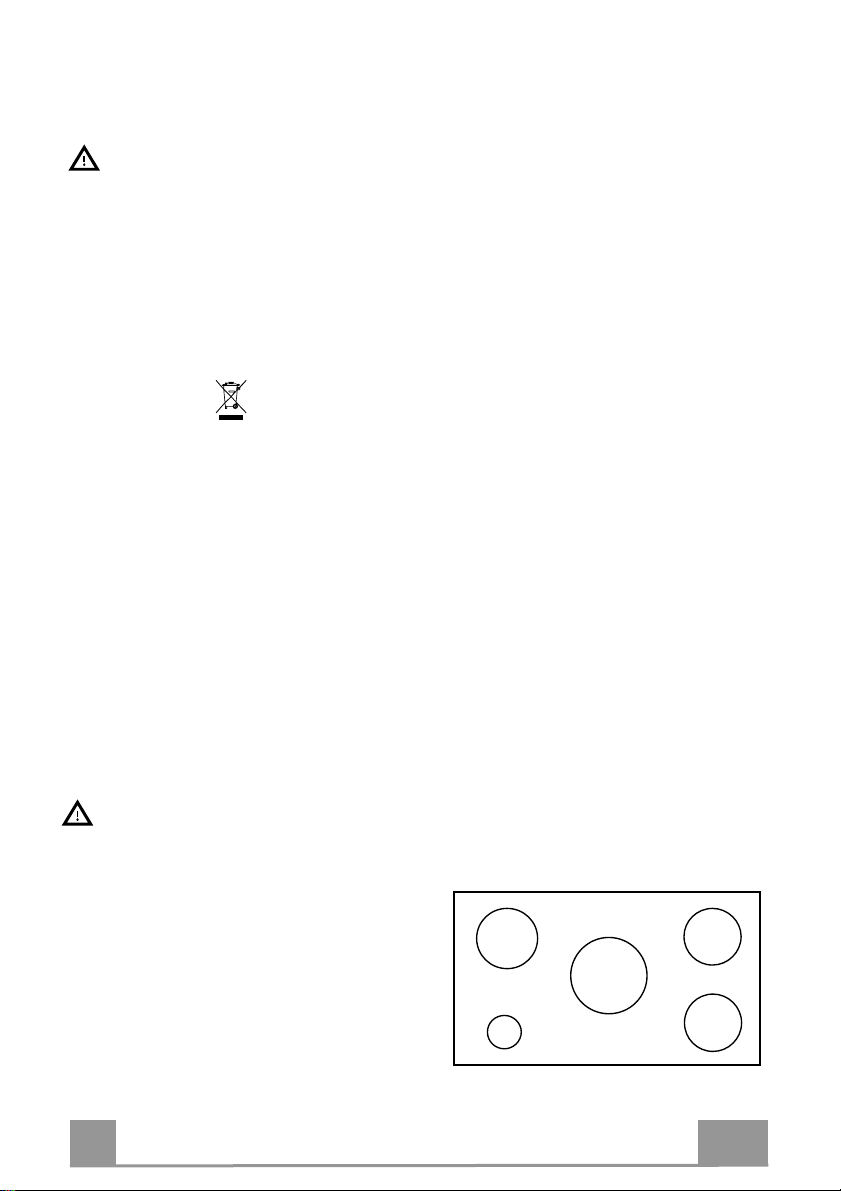
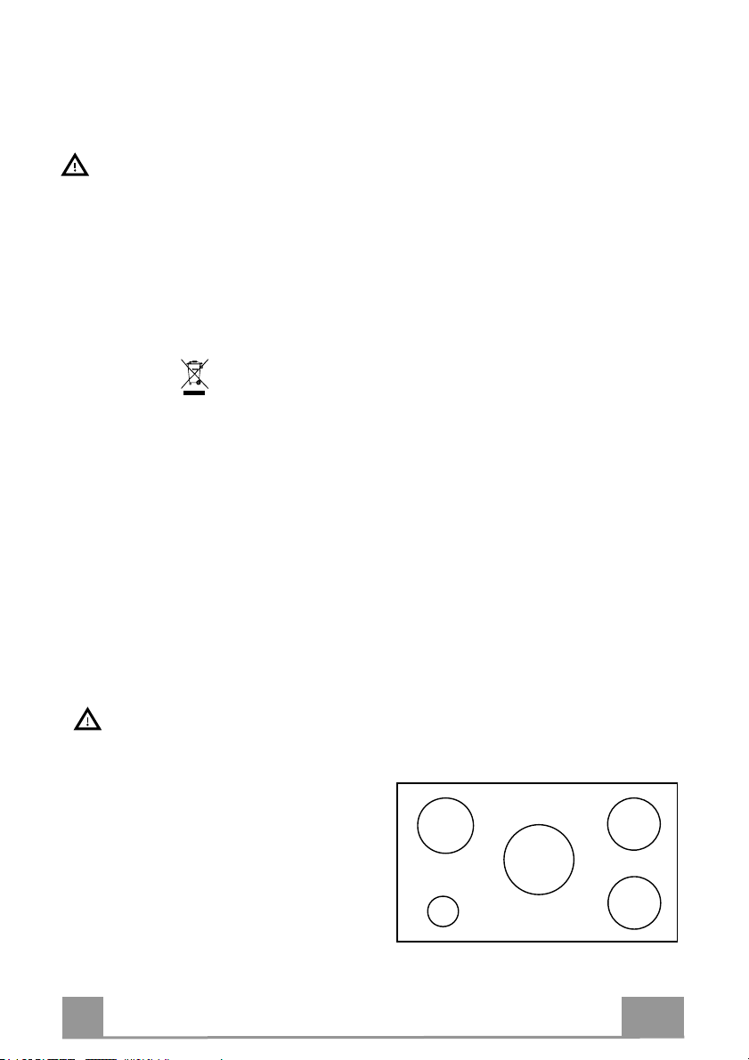
• This Cooker hood can be used in
conjunction with a Gas Cook Top
having the following characteristics:
• Maximum power 12,4 kW
• 5 fire like the picture.
2,6 kW
5 kW
1 kW
1,9 kW
1,9 kW
5
5
Page 6
EN
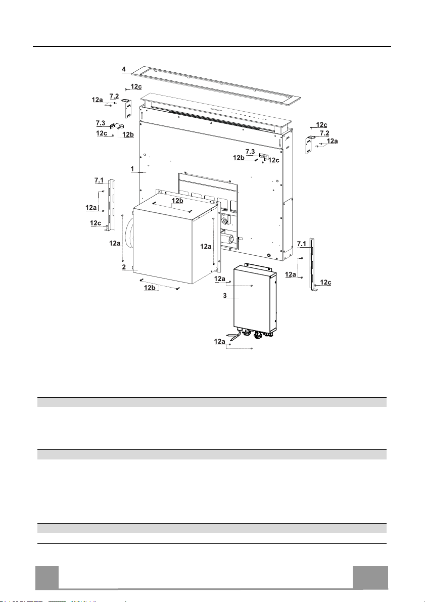
CHARACTERISTICS
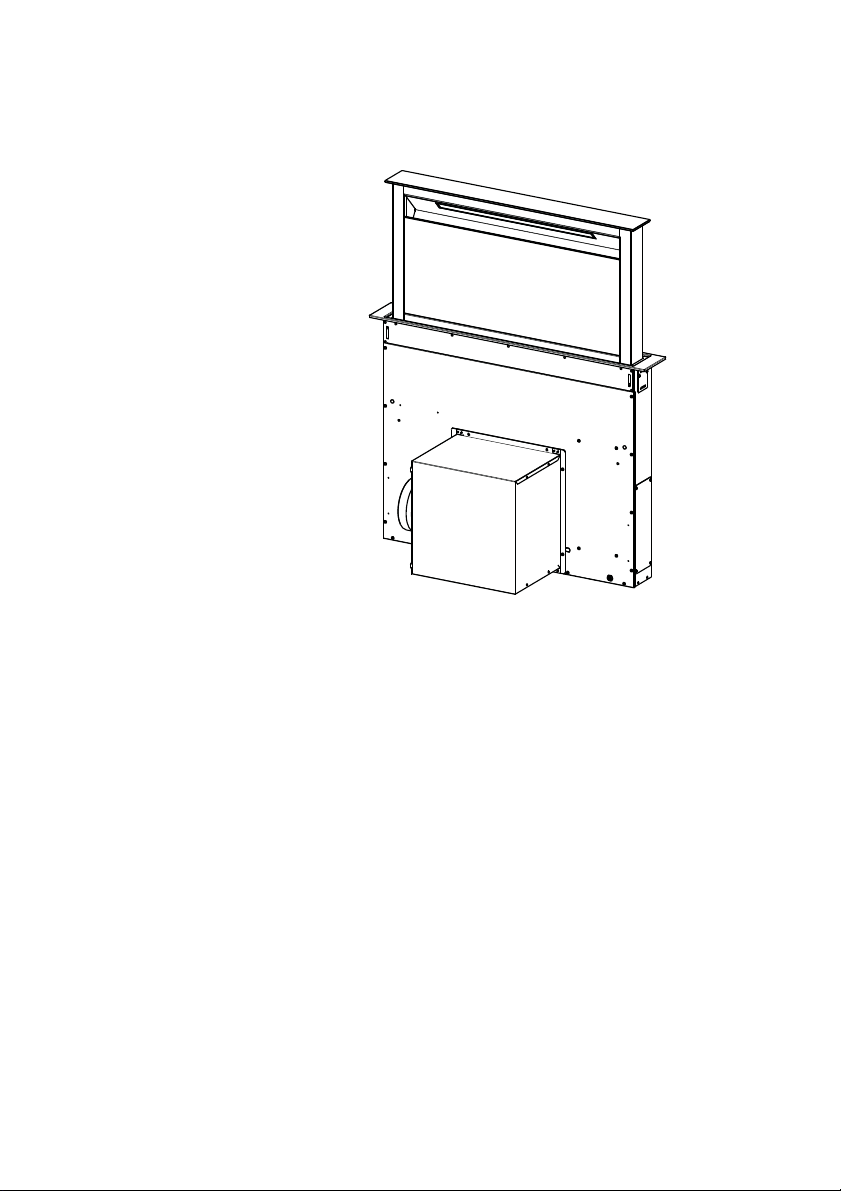
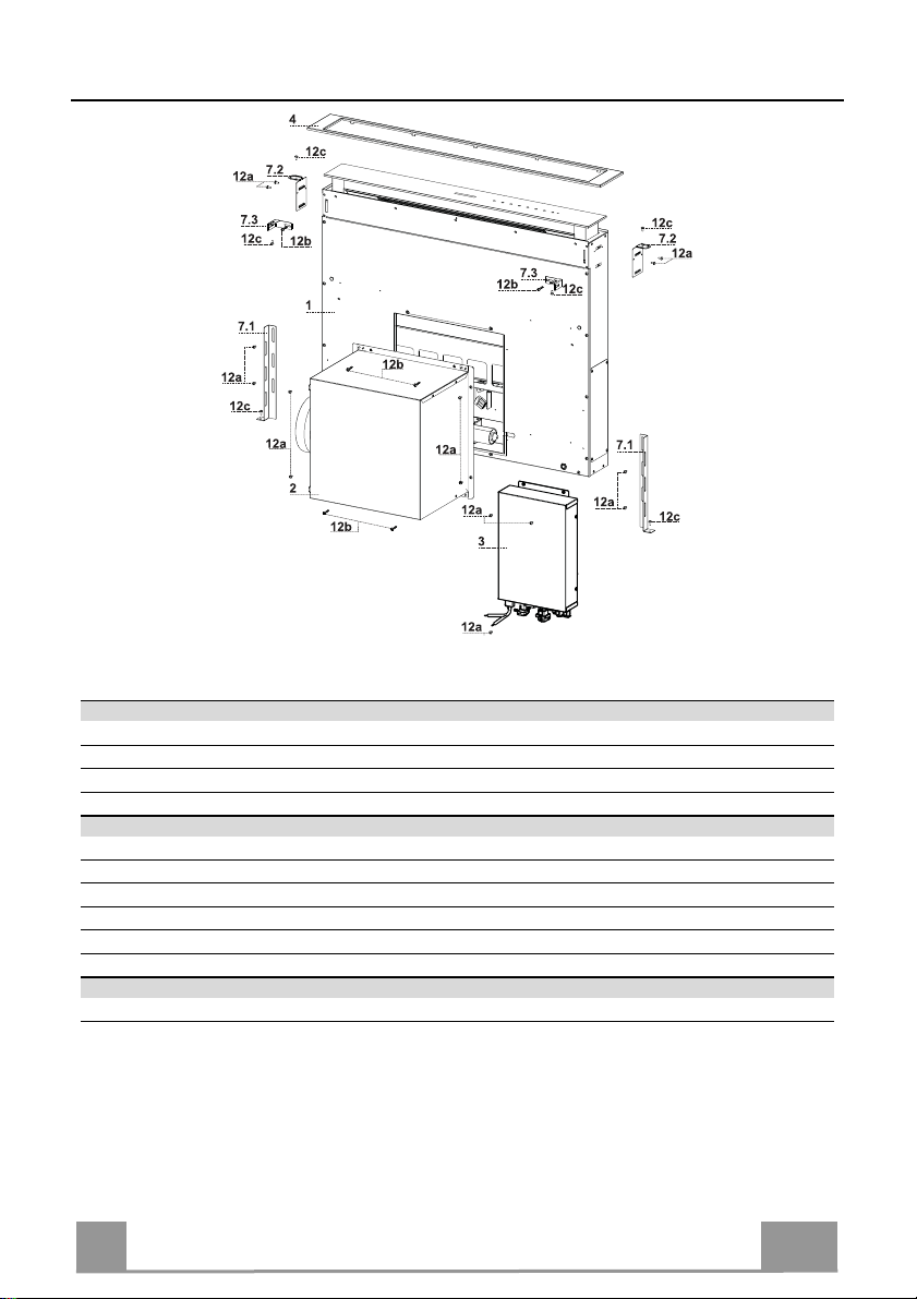
Components
Ref. Q.ty Product Components
1 1 Hood Canopy complete with: Controls, Light, Filters
2 1 Motor unit
3 1 Electric unit
4 1 Front Frame
Ref. Q.ty Installation Components
7.1 2 Splashback Fixing Bracket
7.2 2 Hob Fixing Bracket
7.3 2 Side Bracket
12a 16 Screws 3.5 x 9.5
12b 6 Screws M4 x 8
12c 6 Screws 4 x 15
Q.ty Documentation
1 Instruction Manual
6
6
Page 7
EN
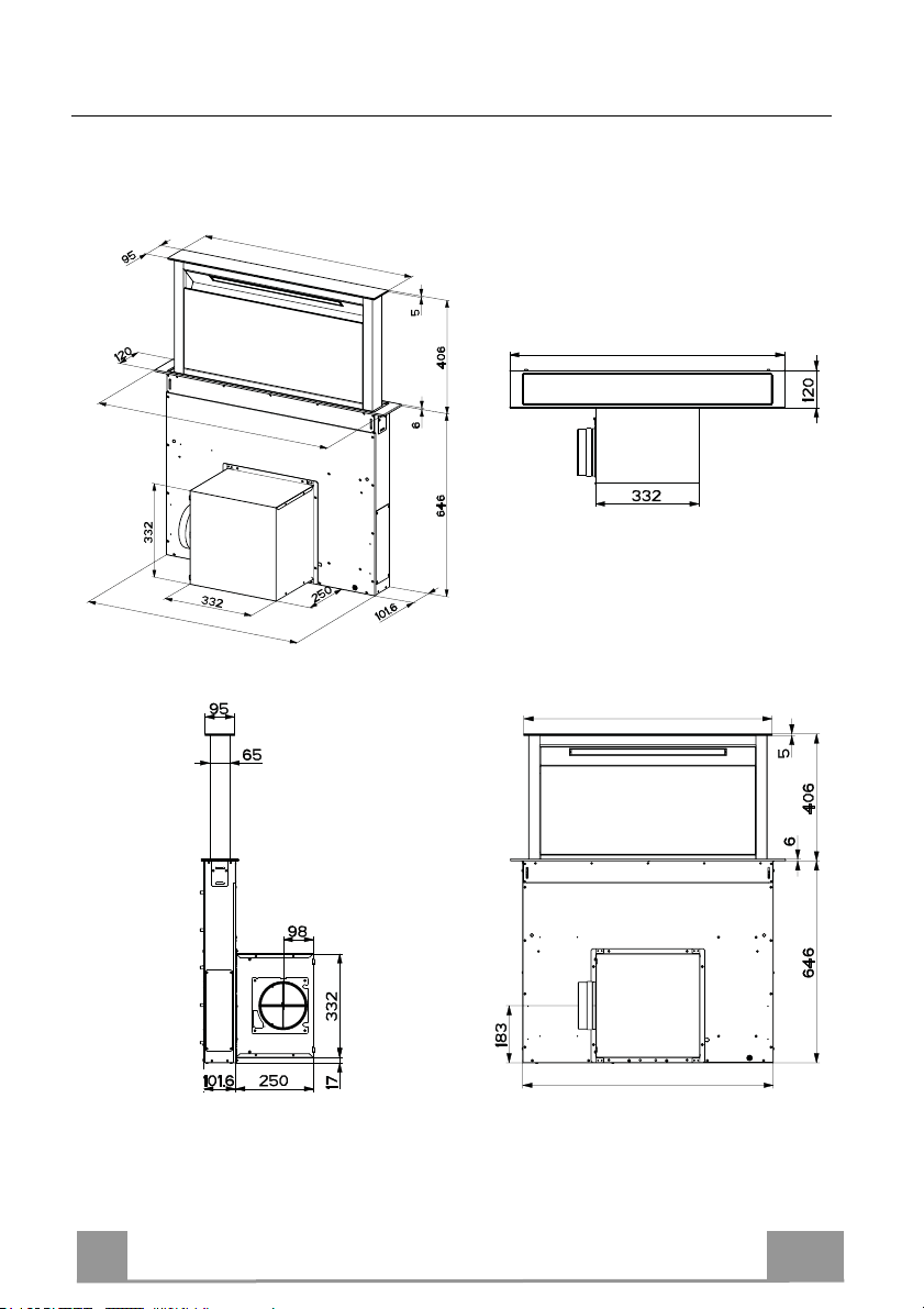
537 - 880
520 - 802
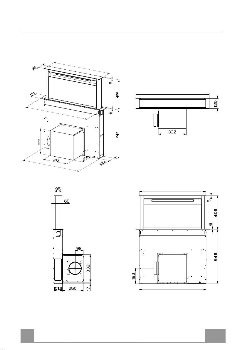
Dimensions
512 - 794
537 - 880
512 - 794
520 - 802
7
7
Page 8
EN
INSTALLATION
This Hood is set up to be fitted inside the kitchen unit in:
• Ducting version: Evacuation to the outside.
• Recirculation version: Internal recirculation.
Sequence of operations - Installation
• Drilling the Support Surface and Fitting the Hood
• Connections
• Functional Check
• Disposal of Packaging
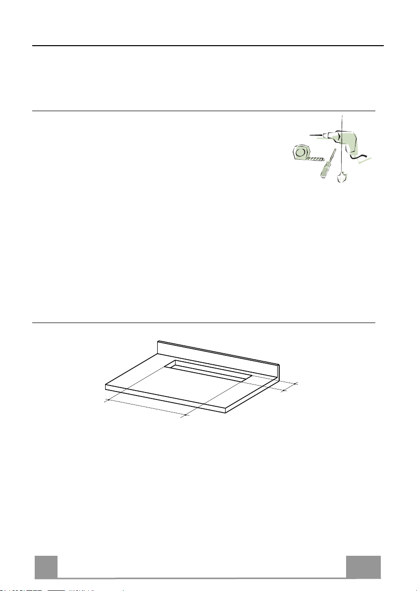
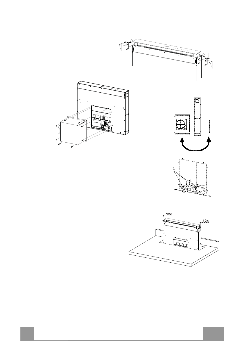
Drilling the Support Surface
109
812
IMPORTANT
The distance between the opening made for the cooker hob and the one for the suction device
must be minimum 3cm - maximum 5cm, according to the strength of the material used for the
top.
8
8
Page 9
EN
7.2
12a
7.2
12a
A
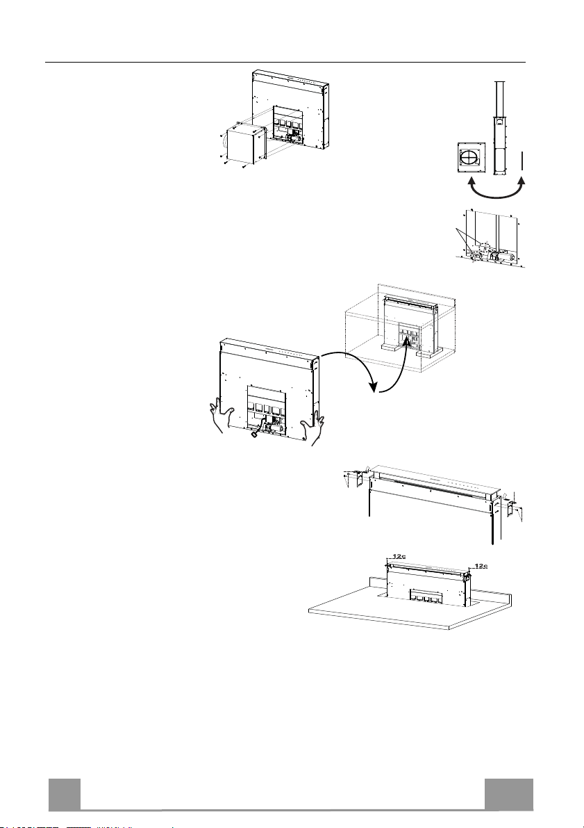
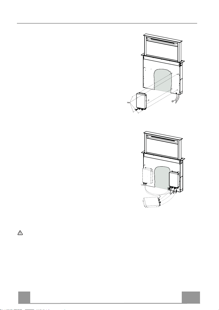
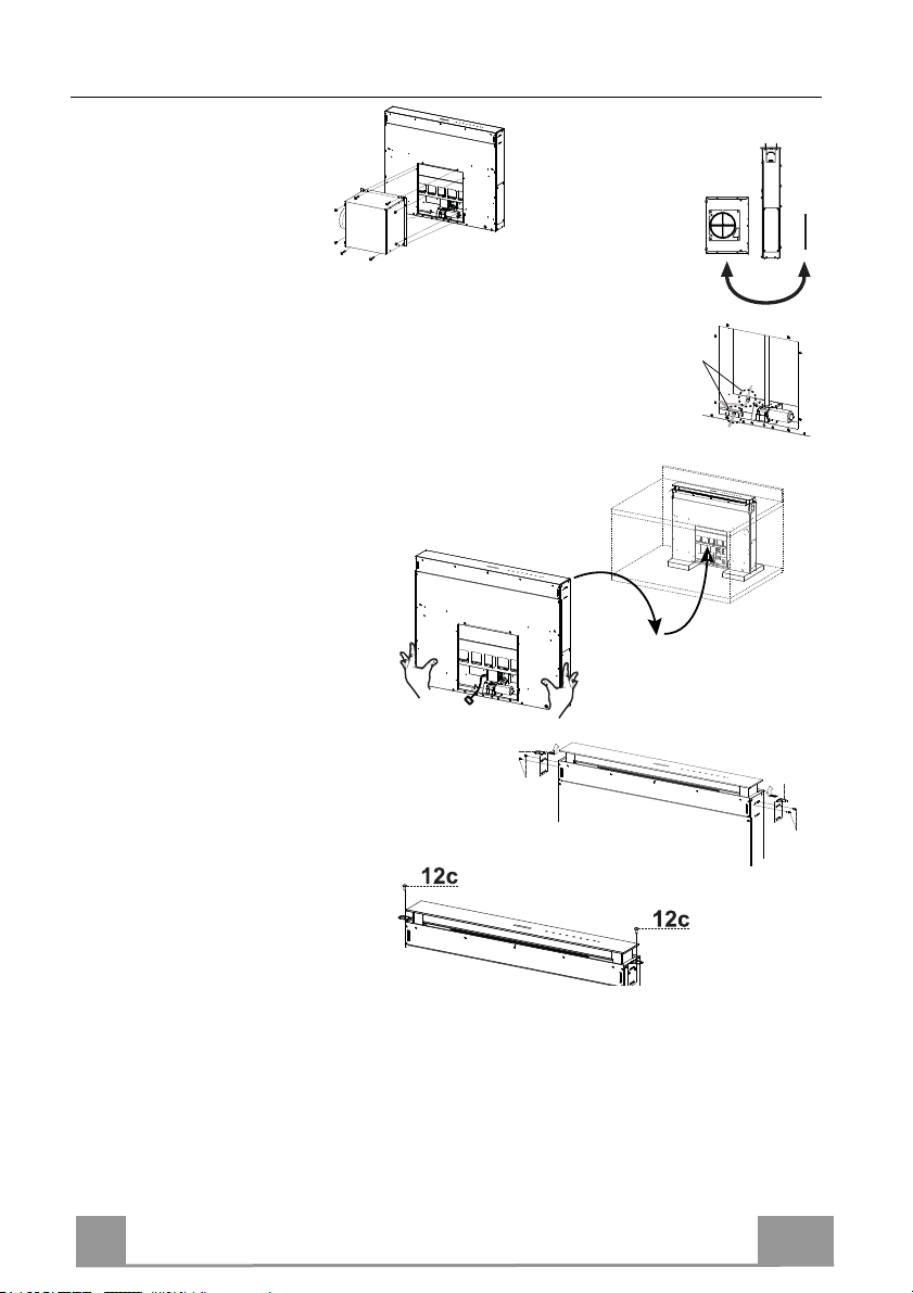
Inserting the Hood Canopy into the support surface from below
• The Hood is built ready for
front installation of the Motor Unit.
• If the kitchen unit is arranged differently and the Motor Unit has to be
fitted on the back, the Plug already fitted on the back of the Hood Canopy must be removed and replaced at the front, and the Cable with cable
raceway for connection of the Motor must also be repositioned using the
slot provided on each side (A).
Before proceeding, the Motor Unit must be fixed to the Hood Canopy
(see paragraph on Fixing the Motor Unit).
• Insert the Hood Canopy
from below into the
support worktop, drilled
as described above.
• With the aid of a support, lift the Hood Canopy until the front
comes out of the Worktop.
• Insert the Brackets 7.2, as indicated in the
figure, into the slots provided and fix them
with the screws 12a provided.
• Centre the Hood Canopy with respect to the
Cooking Hob slot.
• Using the 2 screws 12c provided, fix the
Hood Canopy to the worktop and remove
the supports.
Warning:
If the cooker top is made from a material that does not allow the screws 12c to be inserted, use
a small amount of silicone to glue the Brackets 7.2 to the top and allow it to dry completely
before proceeding with installation
9
9
Page 10
EN 1
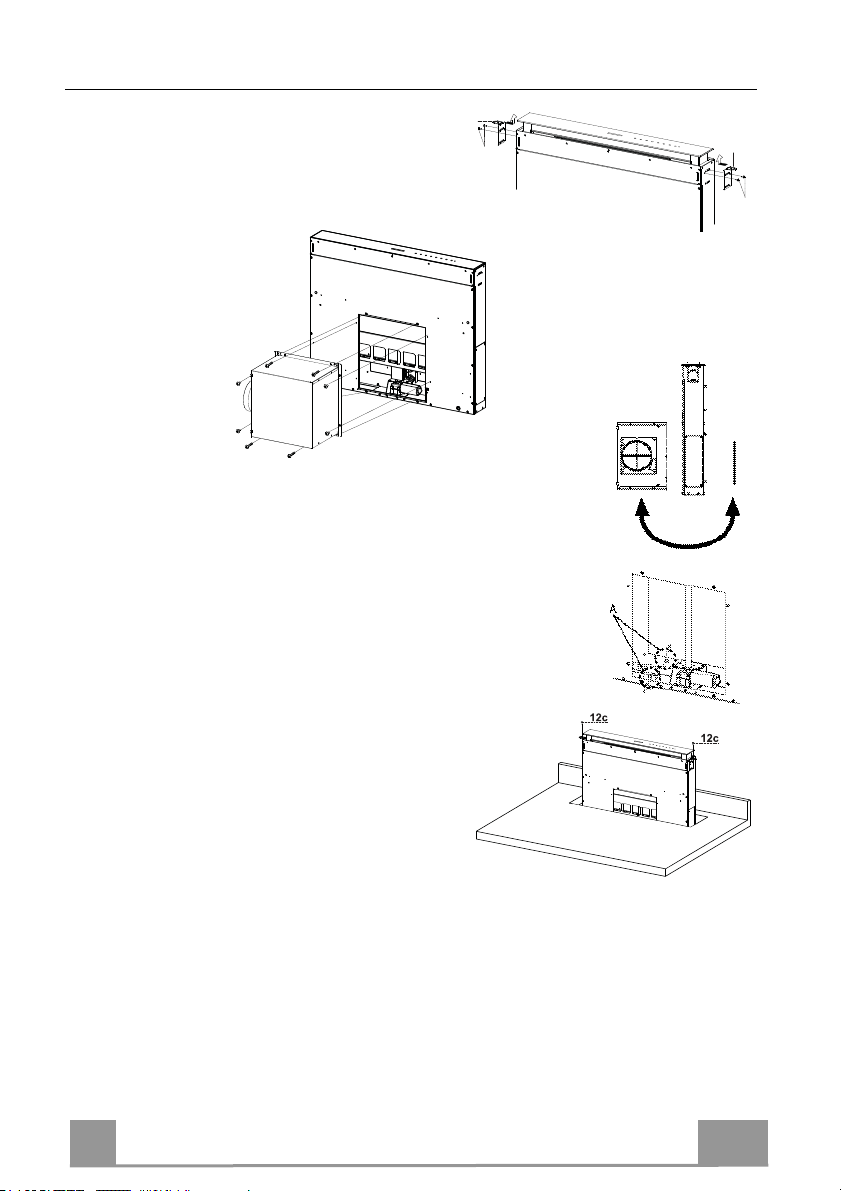
Inserting the Hood Canopy into the support surface from above
7.2
12a
7.2
12a
• Insert the Brackets 7.2, as indicated in the figure, into the slots
provided and fix them with the
screws 12a provided.
• The Hood is built
ready for front in-
stallation of the
Motor Unit.
e kitchen unit is arranged differently and the Motor Unit
• If th
has to be fitted on the back, the Plug already fitted on the back
of the Hood Canopy must be removed and replaced at the front,
and the Cable with cable raceway for connection of the Motor
must also be repositioned using the slot provided on each side
(A).
• Insert the Hood Canopy into the cooker top,
drilled as described above.
• Centre the Hood Canopy with respect to the
Cooking Hob slot.
• Fix the Hood Canopy with the 2 screws 12c
provided.
Warning:
If the cooker top is made from a material that does not allow the screws 12c to be inserted, use
a small amount of silicone to glue the Brackets 7.2 to the top and allow it to dry completely
before proceeding with installation.
10
Page 11
EN 1
12c
12a
7.1
12a
7.1
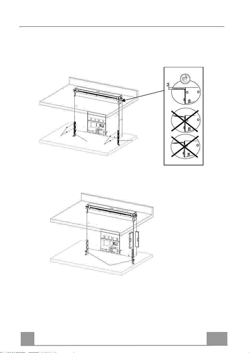
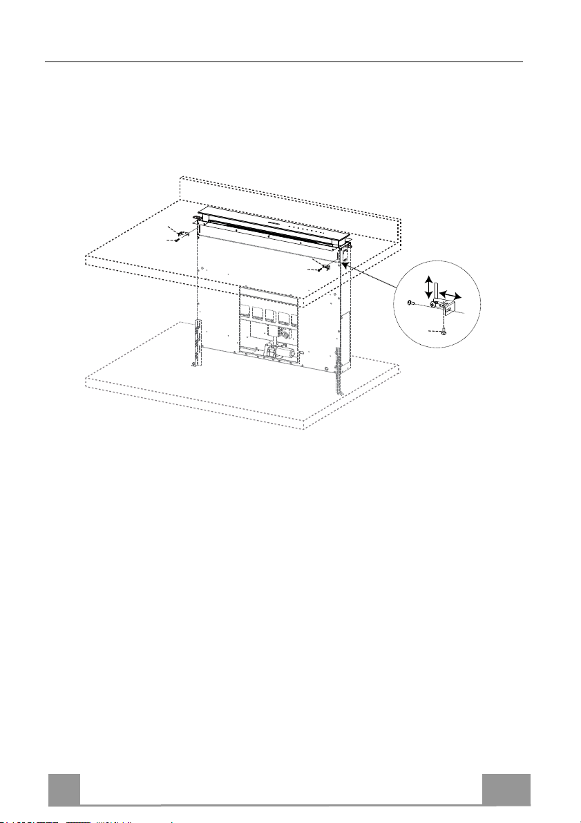
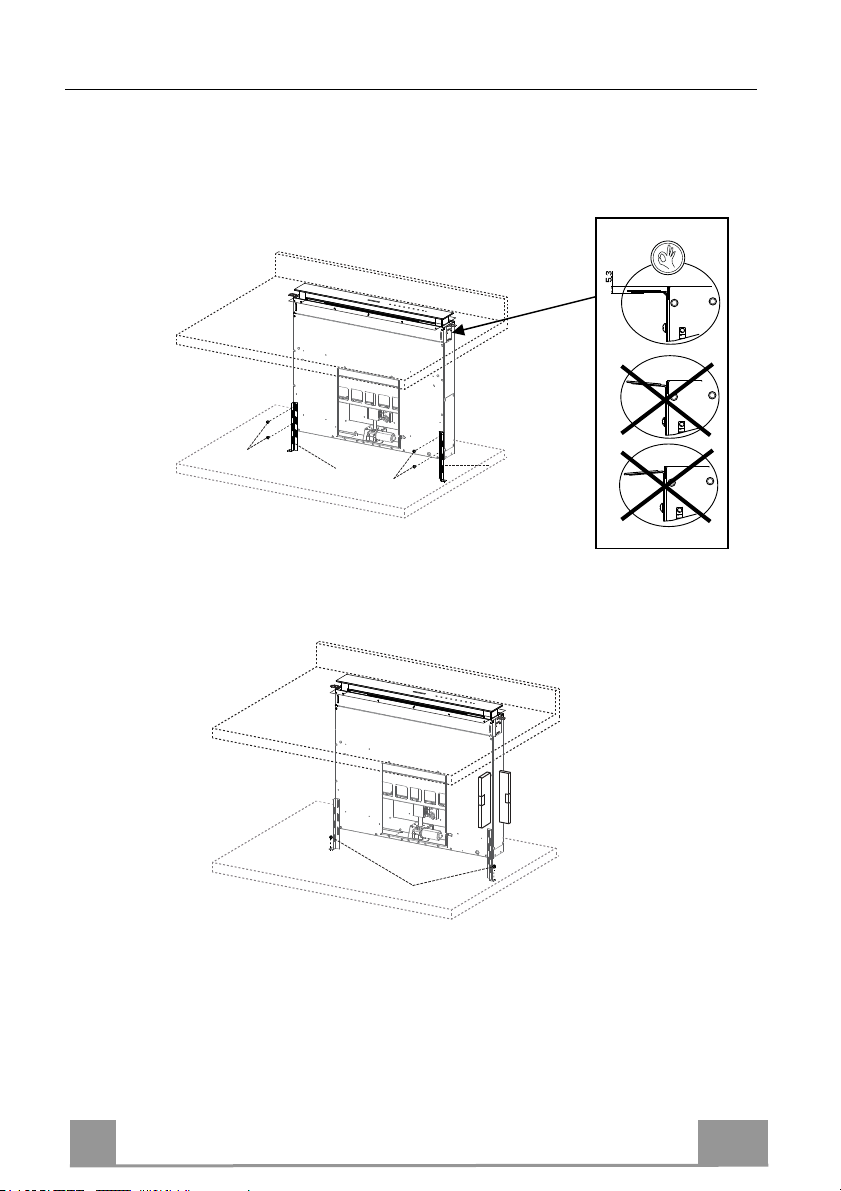
Fixing the Lower Brackets
• Screw the brackets 7.1 to the front of the Hood Canopy using the screws 12a provided.
• Before tightening the Brackets completely, make all the adjustments to allow them to rest on
the lower base of the worktop to avoid deformation of the upper brackets 7.2 as shown in the
figure.
• With the aid of a spirit level, set the Hood Canopy le
Surface using 2 screws 12c provided.
• Tighten the screws 12a completely.
vel vertically and fix it to the Lower
11
Page 12
EN 1
Fixing the Squaring Brackets
12b
7.3
12b
7.3
12c
• Screw the brackets 7.3 to the Hood Canopy using the screws 12b provided, without
tightening completely.
• Using the screws 12c provided, fasten the other part of the brackets 7.3 either to the side
walls of the unit or to the lower part of the cooker top.
• Tighten the screws 12c and 12b completely.
12
Page 13
EN 1
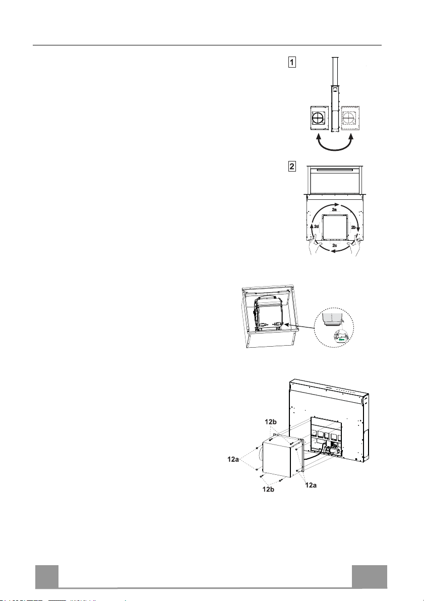
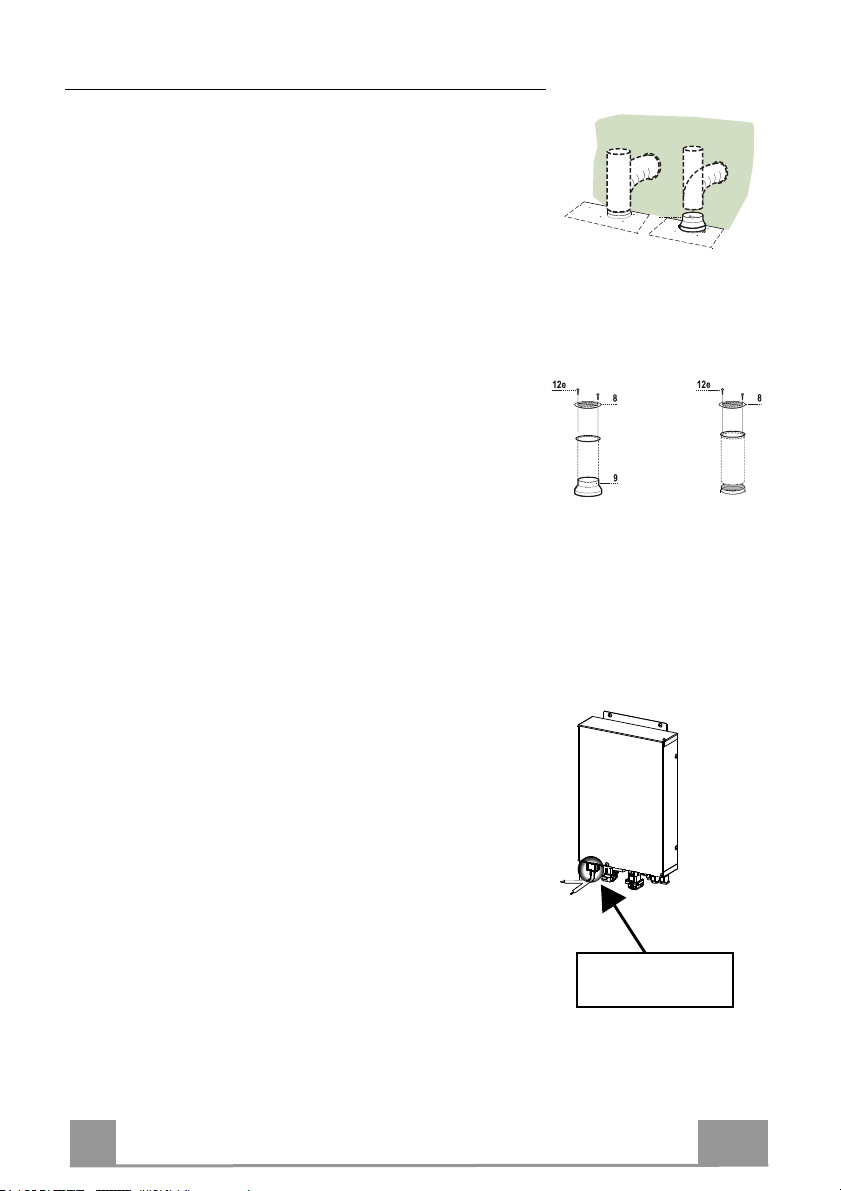
Fixing the Motor Unit
• Installation of the Motor Unit (1) at the front or rear must be decid-
ed according to the position of the Kitchen unit, making sure that
the plug is properly positioned.
• Subsequently, according to where the air outlet opening has been
created on the unit, the Motor Unit can be turned by 90° at a time
so as to allow the air to come out on all 4 sides in correspondence
with the opening in Unit (2).
• Connect the connector from the Hood Canopy to
the Motor Unit connection.
crew the Motor Unit to the Hood Canopy using
• S
the screws 12a and 12b provided as shown in the
figure.
13
Page 14
EN 1
Fixing the Electric Unit
• Connect the Electric cables that come out of the lower
right hand part of the Hood Canopy to the Connectors
on the Electric unit.
• Each cable connector has a corresponding connector
on the Electric Unit, so take care not to make mistakes
when connecting up.
Fix the Electric Unit to the Hood Canopy using the
•
screws 12a provided.
• The position indicated in the figure is only an option,
as if necessary it may also be fitted on the left of the
Hood Canopy or even left free on the base of the unit
if there are no structural or safety problems involved.
Warning..: Do not install the product in such a way that the wiring box is in contact with the floor.
14
Page 15
EN 1
Connections
ø 150
9
ø 120
APPLIANCE
DUCTED VERSION AIR EXHAUST SYSTEM
When installing the ducted version, connect the hood to the
chimney using either a flexible or rigid pipe ø 150 or 120 mm,
the choice of which is left to the installer.
• To install a ø 120 mm air exhaust connection, insert the reducer flange 9 on the hood body outlet.
• Fix the pipe in position using sufficient pipe clamps (not supplied).
• Remove possible charcoal filters.
AIR OUTLET – RECIRCULATION VERSION
• Connect the Flange to the air outlet opening using a rigid or
flexible pipe of ø120 or 150 mm.
• To connect using a ø120 mm pipe, insert the reduction Flange
9 onto the Hood canopy outlet.
• Fasten the pipe using suitable pipe clamps. The materials required to do so are not provided.
• Fix the directional Grid 8 on the outlet, using 2 screws 12e (2.9
x 9.5) provided.
• Make sure that the activated charcoal filters are present (see
paragraph on Activated Charcoal Filter Maintenance).
• Connect the hood to the mains through a two-pole switch hav-
ELECTRICAL CONNECTION
ing a contact gap of at least 3 mm..
IN LET
15
Page 16
EN 1
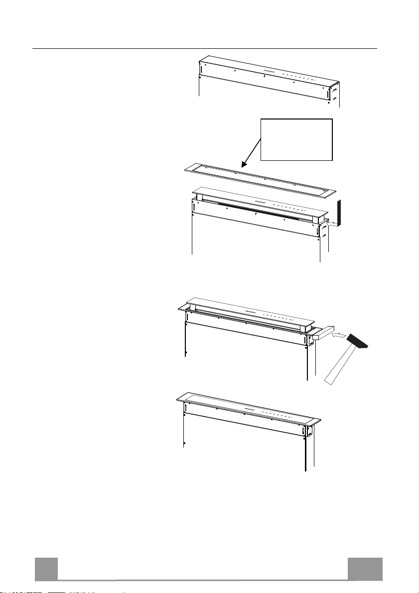
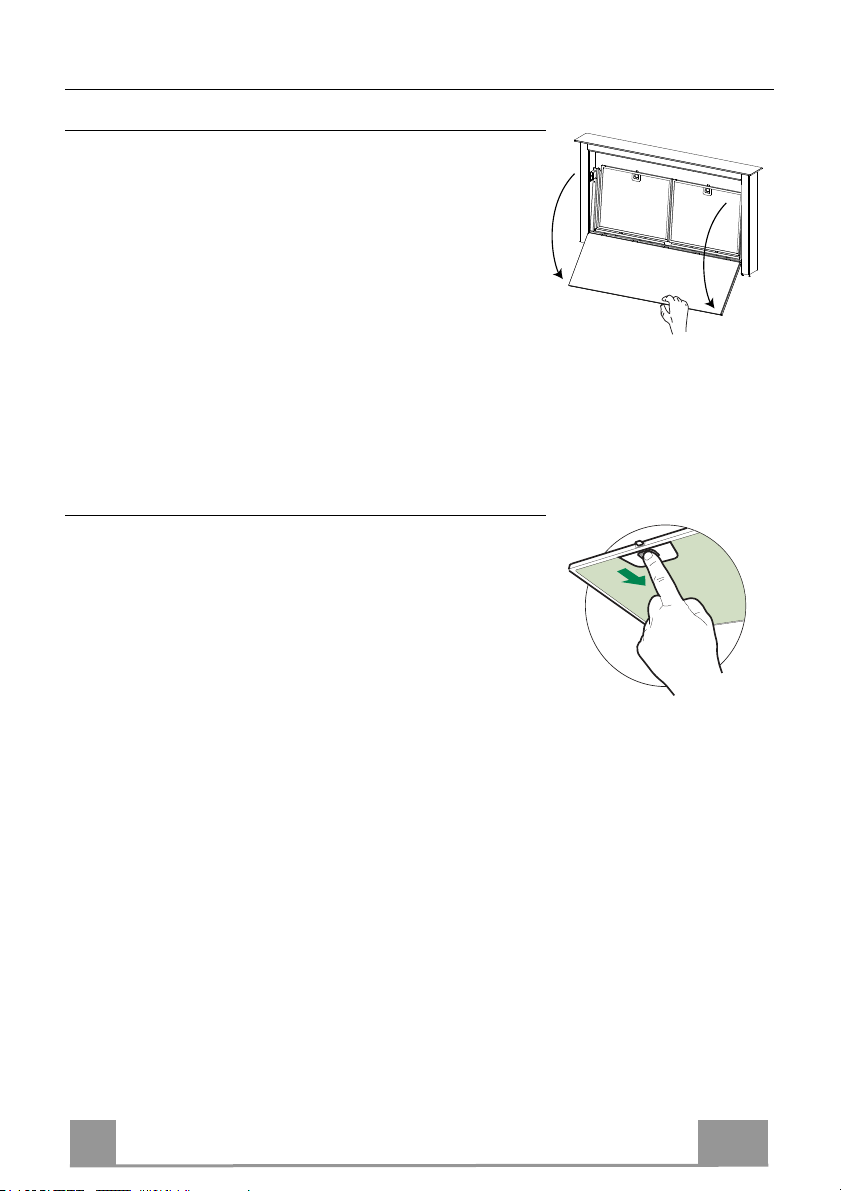
Fitting the Front element
• Lift the mobile hood canopy
(see paragraph on Use) by just a
few centimetres.
• To stop movement, simply
press down on the mobile
canopy as it lifts up.
Warning: Never block the
sliding door when it is opening
or closing, except during the
operations required to fit the
frame.
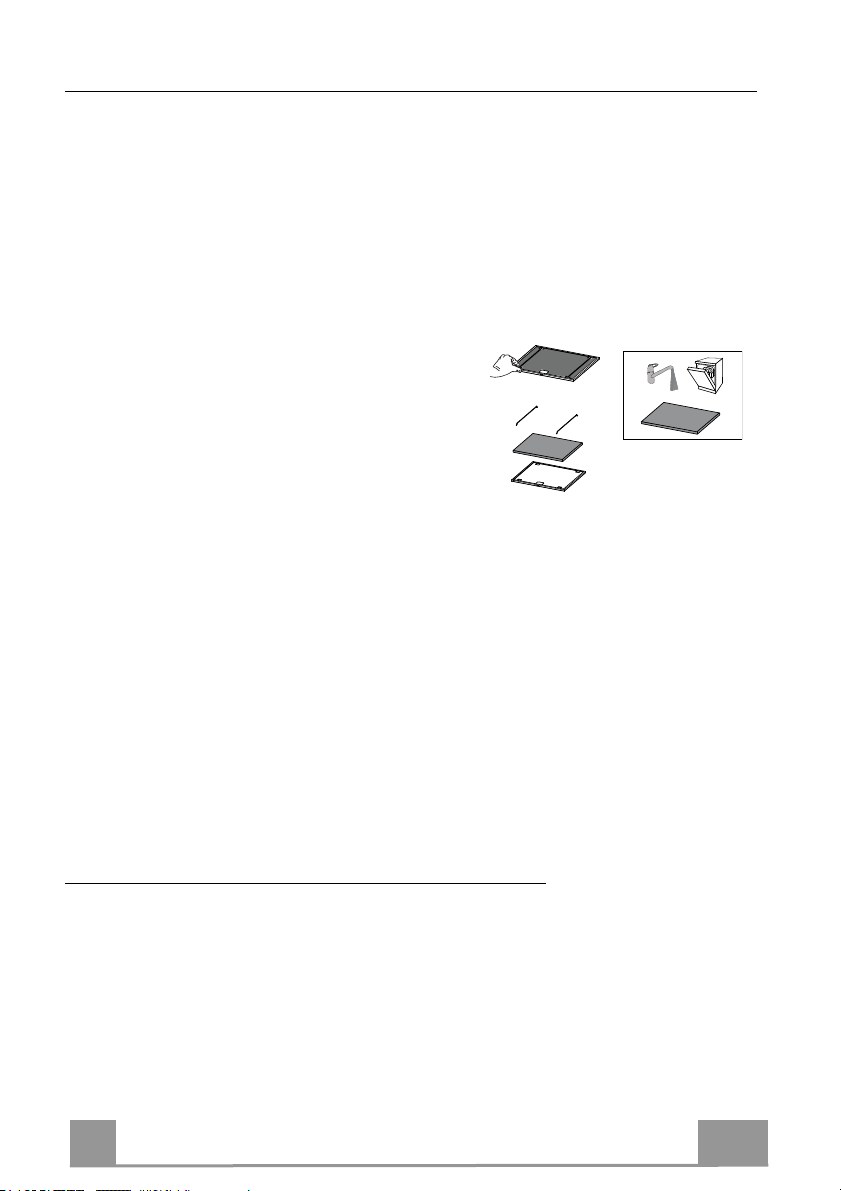
• Remove the sponge guards
from the corners of the glass.
• Take the front Frame and insert
it from above, making sure that
its tabs insert into the slots
provided on the Hood and
sliding it to the left.
Warning..: All the tabs must be
inserted.
• Use a tool (hammer) to tap all
along the front Frame from
right to left until it is
completely flush.
A piece of wood or similar
element can be inserted
between the hammer and the
front Frame to prevent any
damage.
• Please refer to the paragraph on
Use for indications of how to
return the mobile canopy to the
Standard position.
Warning..:
Handle
with care
16
Page 17
EN 1
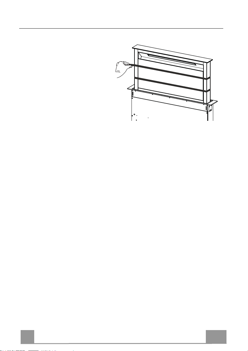
Surround Suction Panel
• Open the Hood Door (see
USE).
• Remove the 2 strips of adhesive
tape fastening the panel during
transport.
17
Page 18

EN 1
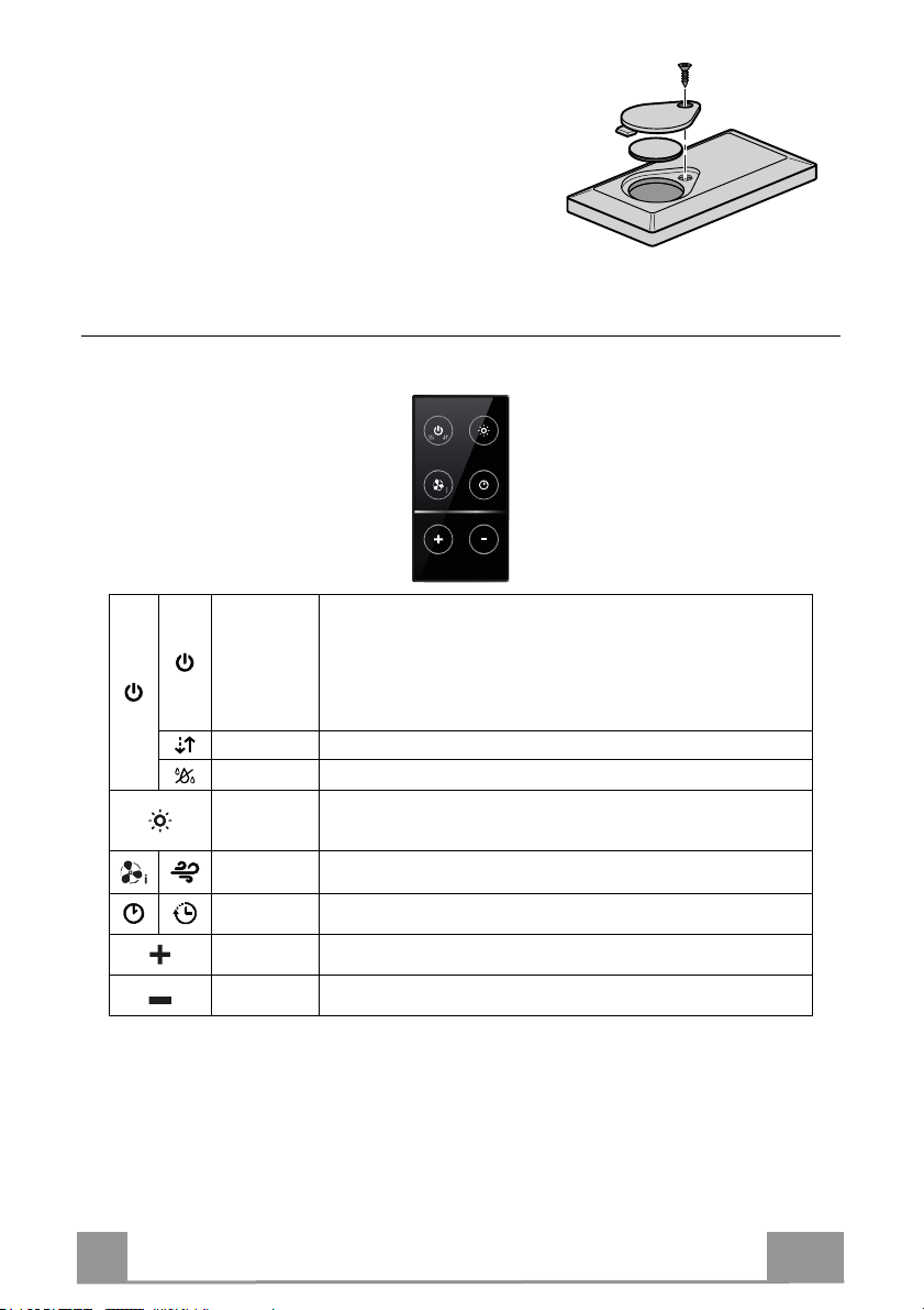
USE
Button Function LED button
Control panel
A The button only works when the door is open.
Press Briefly = Turns the Lights On/Off at maximum intensity.
Press and hold for 2 Seconds = Turns the Courtesy Lights
On/Off.
B Only works with the Door Open.
Press briefly = Activates/Deactivates Delay mode, causing auto-
matic shutdown of the Motor and the Lighting system from any
speed with a 30’ delay. It is disabled by pressing the same button
again, turning the motor off or closing the door.
Works both with the Door Closed and Open.
Press and hold for 2 Seconds = With the filter alarm triggered the
Filter Alarm is Reset, all leds flashing 3 times. These indications
are only visible when the motor is turned off.
C Only works with the Door Open.
Press briefly = Activates speed four.
Only works with the Door Open.
Press and hold for 2 seconds = Enables/Disables the Intensive
speed. This speed is timed to run for 6 minutes. At the end of this
time the system will return to the speed set previously.
It is disabled by pressing the same button again, turning the motor
off or closing the door.
D Only works with the Door Open.
Activates speed three.
E Only works with the Door Open
Activates/Deactivates speed two.
Works both with Door Closed and Open with Motor + Lights =
Off.
Press and hold for 4 Seconds = Enables/disables the Keyboard
lock.
F Only works with the Door Open.
Press briefly = Activates/Deactivates speed one.
Door Open or Closed
Press and hold for 2 Seconds = Enables/Disables the Activated
Charcoal Filter Alarm with the Motor turned off and no Filter
Alarm triggered.
G Door Open
Press briefly = Turns the Motor off
Door Open or Closed
Press and hold for 2 Seconds with Motor and Lights Off =
Enables/Disables the Remote control.
H Door Open = Closes the Door + Lights and Motor Off
Door Closed = Opens the Door + Lights and Motor On.
Warning: If the Door remains partially open for any reason, press
the Button to complete the opening or closing cycle.
LED Button B+ Button for the set Speed are lit.
Fixed LED button:
Indicates the need to wash the metal grease filters.
The alarm is triggered after the Hood has been in
operation for 100 working hours.
Flashing LED button:
Indicates the need to change the activated charcoal
filters, and also to wash the metal grease filters. The
alarm is triggered after the Hood has been in
operation for 200 working hours.
Fixed LED button
Flashing LED button
Fixed LED button
Fixed LED button
All the LED buttons flash twice. During the Lock
the LED buttons light up in sequence.
Fixed LED button
LED button B flashes twice = Activated Charcoal
filter Alarm Activated
LED button B flashes once = Activated Charcoal
filter Alarm Deactivated
LED button goes out
LED button G + F flashes twice = Remote control
Enabled
LED button G + F flashes once = Remote control
Disabled
18
Page 19
EN
1
REMOTE CONTROL (OPTIONAL)
This appliance can be commanded using a remote control,
powered by a CR2032 type 3 V battery (not supplied).
• Do not place the remote control near heat sources.
• Do not discard the batteries with normal waste, they must
be put into the specific containers.
Remote control panel
Warning..: The remote control receiver is deactivated when first supplied. To activate it, see the para-
graph Use.
Door Closed:
Opens the door, turns the motor on at speed one and turns the lights
Motor
- -
- -
Light
Intensive
Delay
-
-
on at maximum intensity.
Door Open:
Brief pressure: Motor On / Off
Pressed for 2 Seconds: Closes the Door and Motor + Lights = Off
Only with Door Open:
Brief pressure: Lights On / Off
Pressed for 2 Seconds: Courtesy lights On / Off
Only with Door Open:
Activates the Intensive function
Only with Door Open:
Activates the Delay function
Only with Door Open:
Increases the working speed each time it is pressed.
Only with Door Open:
Decreases the working speed each time it is pressed.
19
Page 20
EN 2
CARE AND CLEANING
Cleaning the Comfort Panels
• Open the Comfort Panel by pulling it at the top.
• Disconnect the panel from the hood canopy.
• The comfort panel must never be washed in the dishwasher.
• Clean the outside with a damp cloth and neutral detergent.
• Clean the inside using a damp cloth and neutral detergent; do
not use wet cloths or sponges, or jets of water; do not use
abrasive substances.
• On completing the operation, hook the panel and close it.
Metal grease filters
These can also be washed in the dishwasher, and need to be
cleaned whenever button B lights up or at least once every 2
months use, or more frequently if use is particularly intensive.
Resetting the alarm signal
• Turn the Lights and the Suction Motor off.
• Press and hold button B for 2 seconds.
Cleaning the Filters
• Open the Door (see USE).
• Open the Comfort panel by pulling it.
• Remove the Filters one at a time, pushing them towards the
back of the unit and at the same time pulling downward.
• Wash the Filters without bending them, and leave them to dry
completely before replacing. (If the surface of the filter
changes colour as time goes by, this will have absolutely no
effect on the efficiency of the filter itself.)
• Replace, taking care to ensure that the handle faces forwards.
• Close the Comfort panel.
20
Page 21
EN 2
Activated Charcoal Filter (Recirculation Version)
Can be washed in the dishwasher. It must be washed when button B flashes or at least once
every 4 months, or more frequently if use is particularly intense. Guaranteed to operate after
washing for up to a maximum of 5 times before requiring replacement. The Alarm signal, if it
has been activated, only appears when the Suction motor is turned on.
Activating the alarm signal
• In Recirculation Version Hoods, the Filter Saturation Alarm must be activated on installation or at a later date.
• Turn the Lights and the Suction Motor off.
• Press and hold button F for 2 seconds:
• LED B flashes twice – Activated Charcoal Filter saturation alarm ACTIVATED.
• LED B flashes once – Activated Charcoal Filter saturation alarm DEACTIVATED.
CHANGING THE ACTIVATED CHARCOAL FILTER
Resetting the alarm signal
• Turn the Lights and the Suction Motor off.
• Press and hold button B for 2 seconds.
Changing the Filter
• Remove the comfort panel.
• Remove the Metal grease filters.
• Remove the metal filter stops from the grease filter and clean
the saturated activated charcoal odour filter.
• Replace the clean activated charcoal odour filter, hooking it
back up to the grease filter using the metal filter stops.
• Replace the Metal grease filters.
• Close the comfort panel.
Lighting unit
• For replacement contact technical support ("To purchase
contact technical support").
21
Page 22
FR 2
CONSIGNES DE SÉCURITÉ
Pour votre sécurité et pour garantir le fonctionnement correct de
l’appareil, veuillez lire attentivement ce manuel avant d’installer et de
mettre en fonction l’appareil. Toujours conserver ces instructions avec
l’appareil, même en cas de cession ou de transfert à une autre personne.
Il est important que les utilisateurs connaissent toutes les caractéristiques
de fonctionnement et de sécurité de l’appareil.
La connexion des câbles doit être effectuée par un technicien compétent.
• En aucun cas le fabricant ne peut être tenu pour responsable d’éventuels
dommages dus à une installation ou à une utilisation impropre.
• La distance de sécurité minimum entre le plan de cuisson et la hotte
aspirante est de 650 mm (certains modèles peuvent être installés à une
hauteur inférieure ; voir le paragraphe concernant les dimensions de travail
et l’installation).
• Si les instructions d’installation du plan de cuisson à gaz spécifient une
tance supérieure à celle indiquée ci-dessus, veuillez impérativement en
dis
tenir compte.
• Assurez-vous que la tension du secteur correspond à celle indiquée sur la
plaque des caractéristiques apposée à l’intérieur de la hotte.
• Les dispositifs de sectionnement doivent être montés dans l’installation fixe
conformément aux normes sur les systèmes de câblage.
• Pour les appareils de Classe I, s’assurer que l’installation électrique de
votre intérieur dispose d’une mise à la terre adéquate.
• Reliez l’aspirateur du conduit de cheminée avec un tube ayant un diamètre
minimum de 120 mm. Le parcours des fumées doit être le plus court
possible.
• Respecter toutes les normes concernant l’évacuation de l’air.
• Ne reliez pas la hotte aspirante aux conduits de cheminée qui acheminent
les fumées de combustion (par ex. de chaudières, de cheminées, etc.).
22
Page 23
FR 2
•
Si vous utilisez l’aspirateur en même temps que des appareils non électriques
(par ex. fonctionnant au gaz), veillez à ce que la pièce soit adéquatement
ventilée, afin d’empêcher le retour du flux des gaz d’évacuation. Si vous utilisez la
hotte de cuisine en même temps que des appareils non alimentés à l’électricité, la
pression négative dans la pièce ne doit pas dépasser 0,04 mbar, afin d’éviter que
les fumées soient réaspirées dans la pièce où se trouve la hotte.
• Ne pas évacuer l’air à travers une conduite utilisée pour l’évacuation des fumées
des appareils de combustion alimentés au gaz ou avec d’autres combustibles.
• Si le cordon d’alimentation est endommagé, faites-le remplacer par le fabricant ou
par un technicien d’un service après-vente agréé.
• Branchez la fiche à une prise conforme aux normes en vigueur et dans une
position accessible.
• En ce qui concerne les dimensions techniques et de sécurité à adopter pour
l’évacuation des fumées, veuillez vous conformer scrupuleusement aux
règlements établis par les autorités locales.
AVERTISSEMENT : Avant d’installer la hotte, retirer les films de protection.
• Utilisez exclusivement des vis et des petites fournitures du type adapté pour la
hotte.
AVERTISSEMENT toute installation de vis et de dispositifs de fixation non
conformes à ces instructions peut entraîner des risques de décharges
électriques.
• Ne pas observer directement avec des instruments optiques (jumelles, lentilles
grossissantes...).
• Ne flambez pas des mets sous la hotte : sous risque de développer un incendie.
• Cet appareil peut être utilisé par des enfants de plus de 8 ans et par des
personnes dont les capacités physiques, sensorielles ou mentales sont
diminuées ou ayant une expérience et des connaissances insuffisantes, pourvu
que ce soit sous la surveillance attentive d’une personne responsable et après
avoir reçu des instructions sur la manière d’utiliser cet appareil en toute sécurité et
sur les dangers que cela comporte. Assurez-vous que les enfants ne jouent pas
avec cet appareil. Le nettoyage et l’entretien de la part de l’utilisateur ne doivent
pas être effectués par des enfants, à moins qu’ils ne soient surveillés.
• Surveillez les enfants. S’assurer qu’ils ne jouent pas avec l’appareil.
23
Page 24
FR 2
•
Cet appareil n’est pas destiné à être utilisé par des personnes (enfants
compris) dont les capacités physiques, sensorielles ou mentales sont
diminuées ou ayant une expérience et des connaissances insuffisantes, à
moins que celles-ci ne soient attentivement surveillées et instruites.
Les parties accessibles peuvent devenir très chaudes durant l’utilisation
des appareils de cuisson.
• Nettoyer et/ou remplacer les filtres après le délai indiqué (danger
d’incendie). Voir le paragraphe Nettoyage et Entretien.
• Veillez à ce que la pièce bénéficie d’une ventilation adéquate lorsque la
hotte fonctionne en même temps que des appareils utilisant du gaz ou
d’autres combustibles (non applicable aux appareils qui évacuent l’air
uniquement dans la pièce).
• Le symbole
marqué sur le produit ou sur son emballage indique que ce
produit ne peut pas être éliminé comme déchet ménager normal. Lorsque
ce produit doit être éliminé, veuillez le remettre à un centre de collecte
prévu pour le recyclage du matériel électrique et électronique. En vous
assurant que cet appareil est éliminé correctement, vous participez à
prévenir des conséquences potentiellement négatives pour l'environnement
et pour la santé, qui risqueraient de se présenter en cas d’élimination
inappropriée. Pour toute information supplémentaire sur le recyclage de ce
produit, contactez votre municipalité, votre déchetterie locale ou le magasin
où vous avez acheté ce produit.
Introduction/retrait de l’appareil
Danger de blessures !
Danger d’écrasement durant l’introduction et le retrait de l’appareil. Lors
de l’introduction ou du retrait de l'appareil, ne jamais s’arrêter dans la zone
de mouvement de celui-ci. Gardez
les enfants à distance de sécurité.
• Cette hotte aspirante peut être utilisée en
association avec un plan de cuisson à
2,6 kW
5 kW
gaz ayant les caractéristiques suivantes :
• Puissance maximum 12,4 kW
1 kW
• 5 feux, comme illustré dans la figure.
1,9 kW
1,9 kW
24
Page 25
FR 2
CARACTERISTIQUES
Composants
Réf. Q.té Composants du produit
1 1 Corps de hotte équipé de : commandes, éclairage, filtres
2 1 Groupe moteur
3 1 Groupe électrique
4 1 Cadre frontal
Réf. Q.té Composants d’installation
7.1 2 Bride de fixation au fond
7.2 2 Bride de fixation au plan
7.3 2 Bride latérale
12a 16 Vis 3,5 x 9,5
12b 6 Vis M4 x 8
12c 6 Vis 4 x 15
Q.té Documentation
1 Manuel d’instructions
25
Page 26
FR 2
537 - 880
520 - 802
Encombrement
512 - 794
537 - 880
512 - 794
520 - 802
26
Page 27

FR 2
INSTALLATION
Cette hotte est prévue pour être installée à l’intérieur du meuble de cuisine en :
• Version aspirante : évacuation à l’extérieur.
• Version filtrante : recirculation intérieure.
Séquence des opérations d’installation
• Perçage du plan de support et montage de la hotte
• Connexions
• Contrôle fonctionnel
• Élimination des emballages
Perçage du plan de support
109
812
IMPORTANT
La distance entre le trou pratiqué pour la table de cuisson et celui pour l’appareil
d’aspiration doit être de 3 cm minimum et de 5 cm maximum, en fonction de la
résistance du matériau utilisé pour le haut.
27
Page 28
FR 2
7.2
12a
7.2
12a
A
Introduction du corps de hotte dans le plan en passant par le bas
• D’origine, la hotte est prévue pour le montage frontal
du groupe moteur.
• Si la prédisposition du meuble de cuisine est différente et le groupe moteur doit être monté sur la partie arrière, démonter le bouchon déjà fixé
sur le dos du corps de hotte et le remonter frontalement. Remettre aussi
en place le câble avec le passe-câble pour la connexion du moteur en utilisant le trou prévu de chaque côté (A).
Avant de continuer, fixer le groupe moteur au corps de hotte. (Voir para-
graphe Fixation du groupe moteur).
• Enfiler le corps de hotte en
passant sous le plan de support précédemment percé.
• À l’aide d’un support, soulever le corps de hotte jusqu’à
ce que l’élément frontal sorte
du plan.
• Enfiler les brides 7.2, comme indiqué dans la figure, dans les trous prévus et les fixer avec les vis
12a fournies.
• Centrer le corps de hotte par rapport au trou du
plan de cuisson.
• À l’aide de 2 vis 12c fournies,
fixer le corps de hotte au plan
et retirer les supports.
Attention :
Si le matériel du plan de cuisson ne permet pas de serrer les vis 12c, utiliser une petite quantité
de silicone pour coller les brides 7.2 au plan et bien laisser sécher avant de continuer
l’installation.
28
Page 29
FR 2
7.2
12a
7.2
12a
Introduction du corps de hotte dans le plan en passant par le haut
• Enfiler les brides 7.2, comme indiqué dans
la figure, dans les trous prévus et les fixer
avec les vis 12a fournies.
• D’origine, la
hotte est prévue
pour le montage
frontal du
groupe moteur.
• Si la prédisposition du meuble de cuisine est différente et le groupe
moteur doit être monté sur la partie arrière, démonter le bouchon
déjà fixé sur le dos du corps de hotte et le remonter frontalement.
Remettre aussi en place le câble avec le passe-câble pour la connexion du moteur, en passant par le trou prévu de chaque côté (A).
Enfiler le corps de hotte dans le plan de
•
support précédemment percé.
• Centrer le corps de hotte par rapport au trou
du plan de cuisson.
• Fixer le corps de hotte avec 2 vis 12c fournies.
Attention :
Si le matériel du plan de cuisson ne permet pas de serrer les vis 12c, utiliser une petite quantité
de silicone pour coller les brides de support 7.2 au plan et bien laisser sécher avant de continuer l’installation.
29
Page 30
FR 3
Fixation des brides de support inférieures
12c
12a
7.1
12a
7.1
• Fixer frontalement les brides de support 7.1 au corps de hotte avec les vis 12a fournies.
• Avant de serrer définitivement les brides de support, effectuer les réglages leur permettant
de s’appuyer sur la base inférieure du plan, en évitant la déformation des brides de support
supérieures 7.2, comme indiqué dans la figure.
• À l’aide d’un niveau, niveler verticalement le corps de hotte et le fixer au plan inférieur avec
is 12c fournies.
2 v
xer définitivement les vis 12a.
• Fi
30
Page 31

FR 3
Fixation des brides en équerre
12b
7.3
12b
7.3
12c
• Visser les brides 7.3 au corps de hotte avec les vis 12b fournies, sans les serrer.
• Avec les vis 12c fournies, serrer l’autre côté des brides 7.3, soit aux parois latérales du
meuble, soit à la partie inférieure du plan de cuisson.
• Fixer définitivement les vis 12c et 12b.
31
Page 32

FR 3
Fixation du groupe moteur
• L’installation du groupe moteur (1) en position frontale ou
postérieure doit être décidée selon la prédisposition du
meuble de cuisine, en vérifiant que le bouchon est correctement positionné.
• Ensuite, selon l’endroit où a été réalisé le trou de sortie de
l’air sur le meuble, le groupe moteur pourra tourner de 90° à
la fois, afin de permettre la sortie de l’air des quatre côtés en
correspondance de celui du meuble (2).
Relier le connecteur venant du corps de
•
hotte à la connexion du groupe moteur.
• Serrer ensuite le groupe moteur au corps de
hotte avec les vis 12a et 12b fournies,
comme indiqué dans la figure.
32
Page 33

FR 3
Fixation du groupe électrique
• Relier les câbles électriques sortant de la
partie inférieure droite du corps de hotte,
aux connecteurs sur le groupe électrique.
• Tous les connecteurs des câbles ont leur
correspondant sur le groupe électrique, par
conséquent, prenez garde de ne pas vous
tromper lors des connexions.
• Fixer le groupe électrique au corps de hotte
c les vis 12a fournies.
ave
• La position indiquée dans la figure est
seulement une option ; si nécessaire, il peut
également être monté à gauche du corps de
hotte ou même être laissé libre sur la base
du meuble, s’il n’y a pas d’empêchements
structurels ou de sécurité.
Attention : ne pas installer le produit en laissant le boîtier électrique au contact du sol.
33
Page 34

FR 3
Branchements
ø 150
9
ø 120
CONNECTEUR
SORTIE AIR VERSION ASPIRANTE
Pour l’installation en version aspirante, relier la hotte au tube de
sortie au moyen d’un tube rigide ou flexible de ø 150 ou 120 mm
dont le choix est laissé à l’installateur.
• Pour la liaison avec le tube ø120 mm, insérer la buse de réduction 9 sur la sortie du corps de la hotte.
• Fixer le tube avec des colliers serre-tube appropriés. Le
matériel nécessaire n’est pas fourni.
• Retirer les filtres anti-odeur à charbon actif éventuels.
SORTIE AIR VERSION FILTRANTE
• Relier la bride au trou de sortie de l’air avec un tube rigide ou
flexible de ø 120 ou 150 mm.
• Pour la liaison avec le tube ø 120 mm, insérer la buse de
réduction 9 sur la sortie du corps de hotte.
• Fixer le tube avec des colliers serre-tube adaptés. Le matériel
nécessaire n’est pas fourni.
• Fixer la grille orientée 8 sur la sortie à l’aide de 2 vis 12e (2,9 x
9,5) fournies.
• Vérifier la présence des filtres anti-odeur à charbon actif. (Voir
paragraphe Entretien filtres à charbon actif).
• Brancher la hotte sur le secteur en interposant un interrupteur
bipolaire avec ouverture des contacts d’au moins 3 mm.
BRANCHEMENT ELECTRIQUE
D’ALIMENTATION
34
Page 35

FR 3
• Soulever le corps mobile de la
hotte de quelques centimètres
seulement. (Voir paragraphe
Utilisation).
• Pour bloquer le mouvement, il
suffit de faire pression vers le
bas sur le corps mobile qui est
en train de se soulever.
Attention : ne jamais bloquer
la porte coulissante durant les
phases d’ouverture ou de
fermeture, sauf pour le montage
du cadre.
• Retirer les protections en
mousse des coins du verre.
• Saisir le cadre frontal et
l’enfiler par le haut, en veillant
à ce que ses languettes
s’insèrent dans les trous prévus
sur la hotte, puis faire coulisser
le cadre vers la gauche.
Attention : toutes les
languettes doivent être insérées.
• Taper sur le cadre frontal de
droite à gauche à l’aide d’un
outil (marteau) jusqu’en butée.
Pour ne pas l’abîmer, vous
pouvez utiliser un élément
(morceau de bois de la bonne
dimension) entre le marteau et
le cadre frontal.
Montage frontal
Attention :
manier avec
soin
• Se référer au paragraphe
Utilisation pour ramener le
corps mobile en position
standard.
35
Page 36

FR 3
Panneau aspiration périmétrale
• Ouvrir la porte de la hotte.
(Voir paragraphe Utilisation).
• Retirer les deux bandes de ruban adhésif qui fixent le panneau seulement durant le transport.
36
Page 37

FR 3
UTILISATION
Touche Fonction Touche led
Tableau des commandes
A Fonctionne seulement avec la porte ouverte.
Appui bref = Allume/Éteint l’éclairage à l’intensité maximum.
Appui de 2 secondes = Allume/Éteint les lumières de courtoisie.
B Fonctionne seulement avec la porte ouverte.
Appui bref = Branche/Débranche le Delay, l’extinction automa-
tique différée de 30’, du moteur et de l’installation d’éclairage à
partir de n’importe quelle vitesse. Pour la désactiver, appuyer sur
cette même touche, couper le moteur ou fermer la porte.
Fonctionne aussi bien avec la porte fermée qu’ouverte.
Appui de 2 secondes = L’alarme filtres étant en cours, effectuer le
Reset de l’alarme filtres, tous les voyants sont 3 clignotements.
Ces signalisations sont visibles seulement lorsque le moteur est
coupé.
C Fonctionne seulement avec la porte ouverte.
Appui bref = Active la quatrième vitesse.
Fonctionne seulement avec la porte ouverte.
Appui de 2 secondes = Valide/Invalide la vitesse intensive. Cette
vitesse est temporisée à 6 minutes. À la fin de ce délai, le système
retourne à la vitesse précédemment réglée.
Pour la désactiver, appuyer sur cette même touche, couper le
moteur ou fermer la porte.
D Fonctionne seulement avec la porte ouverte.
Active la troisième vitesse.
E Fonctionne seulement avec la porte ouverte.
Active/Désactive la deuxième vitesse.
Fonctionne aussi bien avec la porte fermée qu’ouverte avec
moteur + éclairage = Off.
Appui de 4 secondes = Valide/Invalide le Blocage clavier.
F Fonctionne seulement avec la porte ouverte.
Appui bref = Active/Désactive la première vitesse.
Porte ouverte ou fermée
Appui de 2 secondes = Valide/Invalide l’alarme filtres à
charbon actif avec moteur coupé et sans alarmes filtres en cours.
G Porte ouverte
Appui bref = Coupe le moteur
Porte ouverte ou fermée
Appui de 2 secondes avec moteur et éclairage Off =
Valide/Invalide la télécommande
H Porte ouverte = Ferme la porte + Éclairage et Moteur Off
Porte fermée = Ouvre la porte + Éclairage et Moteur On.
Attention : Si, pour une raison quelconque, la porte est
partiellement ouverte, en appuyant sur la touche la porte
terminera son cycle d’ouverture ou de fermeture.
Touche Led B + touche de la vitesse programmée
allumées.
Touche led fixe :
signale la nécessité de laver les filtres à graisse
métalliques. L’alarme entre en fonction après 100
heures de fonctionnement effectif de la hotte.
Touche led clignotante :
signale la nécessité de remplacer les filtres à charbon
actif. Laver également les filtres à graisse
métalliques. L’alarme entre en fonction après 200
heures de fonctionnement effectif de la hotte.
Touche led fixe
Touche led clignotante
Touche led fixe
Touche led fixe
Toutes les touches leds clignotent 2 fois. Durant le
blocage, les touches leds s’éclairent en séquence.
Touche led fixe
2 Clignotements touche led B = Alarme filtres C.A.
Activée
1 clignotement touche led B = Alarme filtres C.A.
Désactivée
Extinction de la touche led.
2 clignotements touches leds G + F =
Télécommande validée
1 clignotement touches leds G + F = Télécommande
invalidée
37
Page 38

FR 3
TÉLÉCOMMANDE
(FOURNIE SUR DEMANDE)
Cet appareil peut être commandé via une télécommande,
alimentée avec une batterie 3 V type CR2032 (non fournie).
• Ne pas ranger la commande à proximité de sources de
chaleur.
• Ne pas jeter les batteries dans la nature, mais les déposer
dans les bornes de collecte.
Tableau des commandes - Télécommande
Attention : Initialement, le récepteur de la télécommande est désactivé, pour l’activer, voir le para-
graphe Utilisation.
Porte fermée :
Ouvre la porte, branche le moteur à la première vitesse et l’éclairage
à l’intensité maximum.
Moteur
- -
- -
Éclairage
Intensive
Delay
-
-
Porte ouverte :
Appui bref : On / Off Moteur
Appuyée pendant 2 secondes : Ferme la porte et Moteur + Éclairage
= Off
Seulement avec la porte ouverte :
Appui bref : On / Off Éclairage
Appuyée pendant 2 secondes : On / Off Lumières de courtoisie
Seulement avec la porte ouverte :
Active la fonction Intensive
Seulement avec la porte ouverte :
Active la fonction Delay
Seulement avec la porte ouverte :
Augmente la vitesse de fonctionnement à chaque appui.
Seulement avec la porte ouverte :
Diminue la vitesse de fonctionnement à chaque appui.
38
Page 39

FR 3
NETTOYAGE ET ENTRETIEN
Nettoyage des Comfort Panels
• Ouvrir le Comfort Panel en le tirant par le haut.
• Décrocher le panneau du corps de hotte.
• Ne jamais laver le Comfort Panel au lave-vaisselle.
• Le nettoyer à l’extérieur avec un chiffon humide et du détergent liquide neutre.
• Le nettoyer également à l’intérieur avec un chiffon humide et
du détergent neutre ; ne pas utiliser de chiffons ou d’éponges
mouillées, ni de jets d’eau ; ne pas employer de substances
abrasives.
• À la fin de l’opération, raccrocher le panneau au corps de hotte
et le refermer.
Filtres à graisse métalliques
Ils sont lavables même au lave-vaisselle. Ils doivent être lavés
lorsque la touche B s’allume ou au moins tous les 2 mois
d’utilisation environ, ou plus souvent en cas d’utilisation particulièrement intensive.
Reset du signal d'alarme
• Éteindre les lumières et couper le moteur d’aspiration.
• Appuyer sur la touche B pendant 2 secondes.
Nettoyage des filtres
• Ouvrir la porte. (Voir paragraphe Utilisation).
• Ouvrir le Comfort Panel en le tirant.
• Retirer les filtres un à un en les poussant vers la partie
postérieure du groupe et en tirant en même temps vers le bas.
• Laver les filtres en évitant de les plier et les laisser sécher avant
de les remonter. (Un changement de couleur de la surface du
filtre, susceptible de se produire avec le temps, ne nuit en rien à
son efficacité).
• Les remonter en veillant à ce que la poignée soit orientée vers
la partie visible externe.
• Refermer le Comfort Panel.
39
Page 40

FR 4
Filtres anti-odeur à charbon actif (version filtrante)
Également lavable au lave-vaisselle, le nettoyer lorsque la touche B clignote ou au moins tous
les 4 mois ou plus fréquemment en cas d’utilisation particulièrement intense, en garantissant le
fonctionnement jusqu’à un maximum de 5 lavages avant son remplacement. Le signal
d’alarme, si préalablement activé, a lieu seulement lorsque le moteur d’aspiration est en
marche.
Activation du signal d’alarme
• Dans les hottes en version filtrante, activer le signal d’alarme de saturation filtres au moment de l’installation ou après.
• Éteindre l’éclairage et couper le moteur d’aspiration.
• Appuyer sur la touche F pendant 2 secondes :
• 2 clignotements touche led B – Alarme saturation filtre à charbon actif ACTIVÉE
• 1 clignotement touche led B – Alarme saturation filtre à charbon actif DÉSACTIVÉE
REMPLACEMENT DU FILTRE ANTI-ODEUR À CHARBON ACTIF
Reset du signal d'alarme
• Éteindre l’éclairage et couper le moteur d’aspiration.
• Appuyer sur la touche B pendant 2 secondes.
Remplacement du filtre
• Retirer le comfort panel.
• Retirer les filtres à graisse métalliques.
• Retirer les bloque-filtres métalliques du filtre à graisse et
nettoyer le filtre anti-odeur à charbon actif saturé.
• Remonter le filtre anti-odeur à charbon actif propre en le
raccrochant au filtre à graisse à l’aide des bloque-filtres métalliques.
• Remonter les filtres à graisse métalliques.
• Refermer le comfort panel.
Éclairage
• Pour le remplacement, contacter le Service après-vente (« Pour
l’achat, s’adresser au service après-vente »).
40
Page 41

DE 4
SICHERHEITSINFORMATIONEN
Zu Ihrer eigenen Sicherheit und für die korrekte Funktion des Gerätes
lesen Sie bitte diese Betriebsanleitung aufmerksam durch, bevor Sie das
Gerät installieren und benutzen. Verwahren Sie die Bedienungsanleitung
stets zusammen mit dem Gerät, auch wenn Sie dieses an Dritte
weitergeben oder übertragen. Es ist wichtig, dass der Benutzer alle
Betriebs- und Sicherheitsmerkmale des Gerätes kennt.
Die Kabel müssen von einem zuständigen Fachmann angeschlossen
werden.
• Der Hersteller haftet nicht für etwaige Schäden, die durch eine fehlerhafte
Installation oder einen ungeeigneten Gebrauch entstehen könnten.
• Der min. Sicherheitsabstand zwischen Kochfeld und Abzug
beträgt 650 mm (einige Modelle können auch niedriger installiert werden;
siehe Absatz Installation).
• Sollten die Installationsanweisungen des gasbetriebenen Kochfelds einen
größeren Abstand als oben angegeben vorsehen, ist dies zu
berücksichtigen.
• Sicherstellen, dass die Netzspannung der auf dem Typenschild
angegebenen Spannung entspricht. Das Typenschild ist im Inneren der
Haube angebracht.
• Trennvorrichtungen müssen in der festen Anlage gemäß Normen über
Verkabelungssysteme installiert werden.
• Für Geräte der Klasse I sicherstellen, dass das Versorgungsnetz des
Gebäudes korrekt geerdet ist.
• Die Abzugshaube an den Schornstein mit einem Rohr mit
Mindestdurchmesser von 120 mm anschließen. Der Verlauf des
Rauchabzugs muss so kurz wie möglich sein.
• Alle gesetzlichen Vorschriften im Bereich Abluft einhal
• Die Abzugshaube darf nicht an einen Schacht angeschlossen werden, in
den Rauchgase abgeleitet werden (z. B. von Heizkesseln, Kaminen,
usw.).
shaube
ten.
41
Page 42

DE 4
•
Falls die Abzugshaube mit Geräten verwendet wird, die nicht elektrisch
betrieben sind (z.B. Gasgeräte), muss im Raum für eine ausreichende
Belüftung gesorgt werden, damit der Rückfluss der Abgase verhindert wird.
Wird die Abzugshaube zusammen mit nicht elektrisch betriebenen Geräten
eingesetzt, darf der Unterdruck im Raum 0,04 mbar nicht überschreiten, damit
die Abgase nicht wieder angesaugt werden.
• Die Luft darf nicht durch einen Kanal abgelassen werden, der als Rauchabzug
für Gasgeräte oder Geräte verwendet wird, die mit anderen Brennstoffen
betrieben werden.
• Wenn das Gerätekabel beschädigt ist, muss es vom Hersteller oder von einem
Kundendiensttechniker ersetzt werden.
• Den Stecker in eine den einschlägigen Vorschriften entsprechende zugängliche
Steckdose stecken.
• Was die technischen und sicherheitsrelevanten Maßnahmen
für den
Rauchabzug betrifft, sind die Vorgaben der örtlichen Behörden streng
einzuhalten.
WARNUNG: Bevor die Haube installiert wird, die Schutzfolien abziehen.
• Nur für die Abzugshaube geeignete Schrauben und Kleinteile verwenden.
WARNUNG: Die mangelnde Verwendung von Schrauben und
Befestigungselementen gemäß der vorliegenden Anleitung kann zu
Stromschlaggefahr führen.
• Nicht direkt mit optischen Instrumenten (Fernglas, Lupe, usw.) in das Licht
schauen.
• Auf keinen Fall unter der Haube flambieren: Dabei könnte ein Brand entstehen.
• Dieses Gerät darf von Kindern ab 8 Jahren und von Personen mit beschränkten
geistigen, physischen oder sensorischen Fähigkeiten oder mangels Erfahrung
und/oder mangels Wissen benutzt werden, vorausgesetzt, sie werden
aufmerksam beaufsichtigt oder über den sicheren Gebrauch des Geräts und
die damit verbundenen Gefahren eingewiesen. Sicherstellen, dass Kinder nicht
mit dem Gerät spielen. Vom Benutzer auszuführende Reinigungs- und
Wartungsarbeiten dürfen nicht von Kindern ausgeführt werden, sofern sie nicht
dabei beaufsichtigt werden.
• Kinder müssen beaufsichtigt werden, damit sichergestellt wird, dass sie nicht
am G
erät spielen.
42
Page 43

DE 4
•
Dieses Gerät darf nicht von Personen (einschließlich Kindern) mit
beschränkten geistigen, physischen oder sensorischen Fähigkeiten oder
mangels Erfahrung und/oder mangels Wissen benutzt werden, außer sie
werden aufmerksam beaufsichtigt und eingewiesen.
Die frei zugänglichen Teile können während des Kochens mit Kochgeräten
sehr heiß werden.
• Die Filter sind nach den angegebenen Intervallen zu reinigen und/oder zu
ersetzen (Brandgefahr). Siehe Absatz Wartung und Reinigung.
• Wenn die Abzugshaube gleichzeitig mit Geräten verwendet wird, die Gas oder
andere Brennstoffe benutzen, muss im Raum eine ausreichende Belüftung
vorhanden sein (gilt nicht für Geräte, die nur Luft in den Raum ablassen).
• Schutzschild bei Rissbildung ersetzen. Das Symbol am Produkt oder auf
der Verpackung weist darauf hin, dass das Gerät nicht als normaler Hausmüll
entsorgt werden darf. Das ausrangierte Gerät muss vielmehr bei einer
speziellen Sammelstelle für elektrische und elektronische Geräte abgegeben
werden. Mit der vorschriftsmäßigen Entsorgung des Gerätes trägt der
Benutzer dazu bei, schädliche Auswirkungen auf Umwelt und Gesundheit zu
vermeiden. Weitere Informationen zum Recycling dieses Produktes können
bei der zuständigen Behörde, der örtlichen Abfallbeseitigung oder bei dem
Händler, der das Gerät verkauft hat, eingeholt werden.
Montage/Demontage des Geräts
tzungsgefahr!
Verle
Quetschgefahr bei der Montage und Demontage des Geräts. Bei der
Montage oder Demontage des Geräts darf sich niemand im
Bewegungsbereich aufhalten. Kinder in einem Sicherheitsabstand halten.
• Diese Abzugshaube kann über
gasbetriebenen Kochmulden mit den
folgenden Merkmalen verwendet
werden:
2,6 kW
5 kW
1,9 kW
• Max. Leistung 12,4 kW
• 5 Flammen, die wie in der Abbildung
1 kW
1,9 kW
gezeigt.
43
Page 44

DE 4
CHARAKTERISTIKEN
Komponenten
Bez. Menge Produktkomponenten
1 1 Haubenkörper, komplett mit: Bedienelemente, Beleuchtung, Filter
2 1 Motorgruppe
3 1 Elektrik
4 1 Frontrahmen
Bez. Menge Installationskomponenten
7.1 2 Bügel für die Befestigung am Boden
7.2 2 Bügel für die Befestigung am Kochfeld
7.3 2 Seitlicher Bügel
12a 16 Schrauben 3,5 x 9,5
12b 6 Schrauben M4 x 8
12c 6 Schrauben 4 x 15
Menge Dokumentation
1 Betriebsanleitung
44
Page 45

DE 4
537 - 880
520 - 802
Platzbedarf
512 - 794
537 - 880
512 - 794
520 - 802
45
Page 46

DE
4
MONTAGE
Diese Abzugshaube kann in Küchenmöbel eingebaut werden als:
• Abluftversion: Abluftleitung nach Außen.
• Umluftversion: Innere Rezirkulation.
Sequenz der Installationsarbeiten
• Bohrung der Kochfläche und Montage der Haube
• Anschlüsse
• Funktionskontrolle
• Entsorgung des Verpackungsmaterials
Bohrung der Auflagefläche
109
812
WICHTIG
Der Abstand zwischen der Öffnung für das Kochfeld und der Öffnung für die
Abzugshaube muss mindestens 3cm - maximal 5cm betragen, je nach der Festigkeit
des Materials, aus dem das Oberteil besteht.
46
Page 47

DE 4
7.2
12a
7.2
12a
A
Einsetzen des Haubenkörpers in die Arbeitsplattenmaterial von unten
• Die Haube ist werkseitig für
die frontale Montage der Motoreinheit vorbereitet.
• Falls das Küchenmöbel anders vorbereitet ist, muss die Motoreinheit an der
Rückseite montiert werden; dazu wird der an der Rückseite des Haubenkörpers
angebrachte Deckel ausgebaut und an der Frontseite montiert. Ebenso das Kabel mit Lippklampe für den Anschluss des Motors neu positionieren, wobei die
Öse (A) verwendet wird, die an beiden Seiten vorbereitet ist.
Vor dem Fortfahren die Motoreinheit am Haubenkörper befestigen (Siehe Ab-
satz Befestigung der Motoreinheit).
• Den Haubenkörper von unten in die zuvor gebohrte Auflagefläche
schieben.
• Mit Hilfe einer Halterung den
Haubenkörper anheben, bis die
Frontseite aus der Kochfläche hervorragt.
• Die Bügel 7.2 wie abgebildet in die speziellen
Ösen einsetzen und mit den mitgelieferten
Schrauben 12a befestigen.
• Den Haubenkörper mit der Öse der Kochfläche
zentrieren.
• Den Haubenkörper mit den beiden mitgeliefer-
ten Schrauben 12c an der Kochfläche befestigen
und die Halterungen entfernen.
Achtung:
Falls das Material der Kochfläche es nicht erlaubt, die Schrauben 12c einzuschrauben, werden die Bügel
7.2 mit etwas Silikon an der Kochfläche festgeklebt, wobei das Silikon gut trocknen muss, bevor mit der
Installation fortgefahren wird.
47
Page 48

DE 4
7.2
12a
7.2
12a
Einsetzen des Haubenkörpers in die Kochfläche von oben
• Die Bügel 7.2 wie abgebildet in die speziellen Ösen
einsetzen und mit den mitgelieferten Schrauben 12a
befestigen.
• Die Haube ist
werkseitig für
die frontale
Montage der
Motoreinheit
vorbereitet.
• Falls das Küchenmöbel anders vorbereitet ist, muss die Motoreinheit an der
Rückseite montiert werden; dazu wird der an der Rückseite des Haubenkörpers angebrachte Deckel ausgebaut und an der Frontseite montiert. Ebenso
das Kabel mit Lippklampe für den Anschluss des Motors neu positionieren,
wobei die Öse (A) verwendet wird, die an beiden Seiten vorbereitet ist.
• Den Haubenkörper in die zuvor gebohrte
chfläche schieben.
Ko
• Den Haubenkörper mit der Öse
der Kochfläche zentrieren.
• Den Haubenkörper mit
den beiden mitgelieferten Schrauben 12c be-
festigen.
Achtung:
Falls das Material der Kochfläche es nicht erlaubt, die Schrauben 12c einzuschrauben, werden die Bügel
7.2 mit etwas Silikon an der Kochfläche festgeklebt, wobei das Silikon gut trocknen muss, bevor mit der
Installation fortgefahren wird.
48
Page 49

DE
4
Befestigung der unteren Bügel
12c
12a
7.1
12a
7.1
• Die Bügel 7.1 mit den mitgelieferten Schrauben 12a am Haubenkörper befestigen.
• Vor dem definitiven Festziehen der Bügel diese so regulieren, dass sie an der unteren Basis
der Kochfläche aufliegen, und die oberen Bügel 7.2 nicht deformiert werden, wie in der Abbildung gezeigt.
• Mit einer Wasserwaage den Haubenkörper vertikal ausrichten und mit den mitgelieferten
beiden Schrauben 12c an der unteren Kochfläche befestigen.
• Die Schrauben 12a definitiv festziehen.
49
Page 50

DE
5
Befestigung der Winkelbügel
12b
7.3
12b
7.3
12c
• Die Bügel 7.3 mit den mitgelieferten Schrauben 12b am Haubenkörper befestigen, ohne
festzuziehen.
• Den anderen Teil der Bügel 7.3 mit den mitgelieferten Schrauben 12c entweder an den Sei-
tenwänden des Möbels, oder an der Unterseite der Kochfläche befestigen.
• Die Schrauben 12c und 12b definitiv festschrauben.
50
Page 51

DE
5
Montage der Motoreinheit
• Je nach Vorbereitung des Küchenmöbels kann die Motoreinheit (1)
an der Front- oder der Rückseite montiert werden, wobei die korrekte
Position des Deckels zu kontrollieren ist.
• Danach kann die Motoreinheit entsprechend der Position der Ab-
luftöffnung am Möbel um jeweils 90° gedreht werden, so dass der
Luftauslass an allen 4 Seiten auf Höhe der Öffnung am Möbel (2)
ermöglicht wird.
• Den aus dem Haubenkörper austretenden Verbinder mit
Anschluss der Motoreinheit verbinden.
dem
• Danach die Motoreinheit mit den mitge-
lieferten Schrauben 12a und 12b wie ab-
gebildet am Haubenkörper anschrauben.
51
Page 52

DE 5
Montage der Elektrik
• Die rechts unten aus dem Haubenkörper
austretenden Stromkabel an die Verbinder
an der Elektrik anschließen.
• Für jeden Verbinder der Kabel befindet
sich an der Elektrik ein entsprechendes Gegenstück, folglich darauf achten, dass nicht
falsch angeschlossen wird.
Die Elektrik mit den mitgelieferten Schrau-
•
ben 12a am Haubenkörper befestigen.
• Die abgebildete Position ist lediglich ein
Vorschlag, weil die Elektrik bei Bedarf
auch links am Haubenkörper montiert oder
sogar frei an der Basis des Möbels belassen
werden kann, sofern keine strukturellen
Hindernisse oder Sicherheitsbedenken vorliegen.
Achtung: Bei der Installation darf die Abzweigdose nicht in Kontakt mit dem Fußboden bleiben.
52
Page 53

DE
5
Anschluss im Abluftbetrieb
ø 150
9
ø 120
Bei Abluftbetrieb kann die Haube vom Installateur wahlweise
mittels Rohr oder Schlauch (ø 150 oder 120 mm) an die Außenrohrleitung angeschlossen werden.
• Bei Verwendung eines Anschlussrohres ø 120 den Reduzier-
flansch 9 am Haubenaustritt anbringen.
• Das Rohr mit geeigneten Rohrschellen fixieren. Das hierzu
erforderliche Material wird nicht mitgeliefert.
• Eventuell vorhandene Aktivkohlefilter entnehmen.
LUFTAUSTRITT BEI DER UMLUFTVERSION
• Den Flansch mit einem starren oder flexiblen Rohr mit ø 120
oder 150 mm an die Abzugsöffnung anschließen.
• Für den Anschluss mit einem Rohr mit ø 120 den
Reduzierflansch 9 am Auslass am Haubenkörper einsetzen.
• Das Rohr mit geeigneten Rohrschellen fixieren. Das hierzu
erforderliche Material wird nicht mitgeliefert.
• Das Luftstromrichtungsgitter 8 mit den 2 mitgelieferten
Schrauben 12e (2,9 x 9,5) am Auslass befestigen.
• Sicherstellen, dass die Aktivkohle-Geruchsfilter vorhanden
sind (Siehe Absatz Wartung der Aktivkohlefilter).
ELEKTROANSCHLUSS
• Bei Anschluss der Haube an das Stromnetz muss ein zweipoli-
ger Schalter mit einem Öffnungsweg von mindestens 3 mm
zwischengeschaltet werden.
STROMANSCHLUSS
53
Page 54

DE 5
behandeln
• Den beweglichen Haubenkör-
per um wenige Zentimeter anheben (Siehe Absatz Gebrauch).
• Um die Bewegung zu blockie-
ren, einfach auf den beweglichen Haubenkörper einen
Druck nach unten ausüben.
Achtung: Die verschiebbare
Klappe nie während der Phase
des Öffnens oder Schließens
blockieren, außer wenn der
Rahmen montiert werden soll.
• Die Schutzecken aus Schaum-
stoff von der Glasscheibe nehmen.
• Den Frontrahmen zur Hand
nehmen, von oben so einschieben, dass seine Laschen in die
Ösen an der Haube passen und
nach links gleiten lassen.
Achtung: Alle Laschen müssen
eingeschoben sein.
• Mit einem Werkzeug (Ham-
mer) von rechts nach links auf
den Frontrahmen klopfen, bis er
sich am Anschlag befindet.
Um Beschädigungen zu ver-
meiden, kann ein passendes
Stück Holz zwischen Hammer
und Frontrahmen eingelegt
werden.
• Um den beweglichen Hauben-
körper wieder auf die standardmäßige Position zu bringen, den Absatz Gebrauch konsultieren.
Frontale Montage
Achtung:
Vorsichtig
54
Page 55

DE 5
• Die Klappe öffnen (siehe Ab-
satz Gebrauch).
• Die beiden Klebestreifen ent-
fernen, welche das Paneel während des Transports fixieren.
Umlaufendes Saugpaneel
55
Page 56

DE 5
BEDIENUNG
Taste Funktion LED Taste
Schalttafel
Die Taste funktioniert nur bei geöffneter Klappe.
A
Kurzes Drücken: schaltet die Beleuchtung bei maximaler Intensität ein/aus.
2 Sekunden langes Drücken: schaltet die Notbeleuchtung ein/aus.
B Funktioniert nur bei geöffneter Klappe.
Kurzes Drücken: aktiviert/deaktiviert die Funktion Delay, das automatische
Abschalten von Motor und Beleuchtung mit einer Verzögerung von 30', von
jeder Geschwindigkeitsstufe aus. Wird durch Drücken derselben Taste,
Abstellen des Motors oder Schließen der Klappe deaktiviert.
Funktioniert bei geschlossener und geöffneter Klappe.
2 Sekunden langes Drücken: Bei vorliegendem Filteralarm erfolgt ein Reset des
Filteralarms, alle LEDs 3 blinkt. Derlei Anzeigen sind nur bei abgestelltem
Motor sichtbar.
C Funktioniert nur bei geöffneter Klappe.
Kurzes Drücken: Schaltet die vierte Betriebsgeschwindigkeit ein.
Funktioniert nur bei geöffneter Klappe.
2 Sekunden langes Drücken: Aktiviert/deaktiviert die Intensivgeschwindigkeit.
Diese Geschwindigkeit ist auf 6 Minuten zeitgeregelt. Nach Ablauf dieser Zeit
kehrt das System zu der zuvor eingestellten Geschwindigkeit zurück.
Wird durch Drücken derselben Taste, Abstellen des Motors oder Schließen der
Klappe deaktiviert.
D Funktioniert nur bei geöffneter Klappe.
Schaltet die dritte Betriebsgeschwindigkeit ein.
E Funktioniert nur bei geöffneter Klappe
Schaltet die zweite Betriebsgeschwindigkeit ein.
Funktioniert bei geschlossener und geöffneter Klappe bei Motor + Beleuchtung
= Off.
4 Sekunden langes Drücken: Aktiviert/deaktiviert die Tastatursperre.
F Funktioniert nur bei geöffneter Klappe.
Kurzes Drücken: Schaltet die erste Betriebsgeschwindigkeit ein.
Klappe geöffnet oder geschlossen
2 Sekunden langes Drücken: Aktiviert/deaktiviert den Alarm der
Aktivkohlefilter bei abgestelltem Motor und ohne vorliegende Filteralarme.
G Klappe offen:
Kurzes Drücken: Abstellen des Motors
Klappe geöffnet oder geschlossen
2 Sekunden langes Drücken bei Motor und Beleuchtung Off:
Aktiviert/deaktiviert die Fernbedienung.
H Klappe geöffnet: Schließt Klappe + Beleuchtung und Motor Off
Klappe geschlossen: Öffnet Klappe + Beleuchtung und Motor On
Achtung: Falls die Klappe aus irgendeinem Grund teilweise offen ist, wird bei
Drücken der Zyklus für Öffnen oder Schließen beendet.
Eingeschaltet LED Taste B + Taste der eingestellten
Geschwindigkeitsstufe.
LED Taste bleibend eingeschaltet:
Zeigt an, dass die Metallfettfilter gewaschen werden müssen. Dieser
Alarm wird nach 100 effektiven Betriebsstunden der Abzugshaube
ausgelöst.
LED Taste blinkt:
Zeigt an, dass die Aktivkohlefilter ausgewechselt und die Metallfettfilter
gewaschen werden müssen. Dieser Alarm wird nach 200 effektiven
Betriebsstunden der Abzugshaube ausgelöst.
LED Taste bleibend eingeschaltet
LED Taste blinkt:
LED Taste bleibend eingeschaltet
LED Taste bleibend eingeschaltet
Alle Tasten blinken 2 Mal. Während der Tastatursperre schalten sich die
LED Tasten sequentiell ein.
LED Taste bleibend eingeschaltet
2 Mal Blinken LED Taste B: Alarm der Aktivkohlefilter aktiviert
1 Mal Blinken LED Taste B: Alarm der Aktivkohlefilter deaktiviert
Ausschalten der LED Taste
2 Mal Blinken der LED Tasten G + F: Fernbedienung aktiviert
1 Mal Blinken der LED Tasten G + F: Fernbedienung deaktiviert
56
Page 57

DE
5
FERNBEDIENUNG (OPTION)
Dieses Gerät kann per Fernbedienung, die mit einer 3VBatterie vom Typ CR2032 (nicht mitgeliefert) versorgt wird,
bedient werden.
• Die Fernbedienung nicht in der Nähe von Wärmequellen
ablegen.
• Altbatterien zum Schutz der Umwelt in Sammelboxen
entsorgen.
Bedienfeld der Fernbedienung
Achtung: Das Empfangsteil der Fernbedienung ist anfangs deaktiviert. Für die Aktivierung siehe
Absatz Gebrauch .
Klappe geschlossen:
Öffnet die Klappe und schaltet den Motor bei der ersten
Geschwindigkeitsstufe und stärkster Beleuchtung ein.
Motor
- -
- -
Beleuchtung
Intensivgeschwindigkeit
Delay
-
-
Klappe offen:
Kurzes Drücken: On / Off Motor
2 Sekunden langes Drücken: Schließt die Klappe und Motor
+ Beleuchtung = Off
Nur bei geöffneter Klappe:
Kurzes Drücken: On / Off Beleuchtung
2 Sekunden langes Drücken: On / Off Notbeleuchtung
Nur bei geöffneter Klappe:
Aktiviert die Intensivgeschwindigkeit.
Nur bei geöffneter Klappe:
Aktiviert die Funktion Delay.
Nur bei geöffneter Klappe:
Erhöht bei jedem Drücken die Betriebsgeschwindigkeit.
Nur bei geöffneter Klappe:
Vermindert bei jedem Drücken die Betriebsgeschwindigkeit.
57
Page 58

DE
5
REINIGUNG UND WARTUNG
Reinigung der Komfort-Paneele
• Die Oberseite des Komfort-Paneels nach oben herausziehen.
• Das Paneel vom Haubenkörper lösen.
• Das Komfort-Paneel darf auf keinen Fall im Geschirrspüler gespült
werden.
• Die Außenflächen mit einem feuchten Lappen und einem neutralen
Flüssigreiniger säubern.
• Auch Innen mit einem feuchten Lappen und einem neutralen
Reinigungsmittel säubern; keine nassen Tücher oder Schwämme, oder
gar Wasser verwenden, und keine schleifenden Mittel einsetzen.
Metallfettfilter
Die Fettfilter sind spülmaschinengeeignet und müssen gewaschen
werden, sobald sich die Taste B einschaltet, oder mindestens alle
2 Monate, oder auch öfter, je nach Intensität des Gebrauchs.
Reset des Alarmsignals
• Die Beleuchtung und den Absaugmotor abstellen.
• Die Taste B 2 Sekunden lang drücken.
Reinigung der Filter
• Die Klappe öffnen (siehe Gebrauch).
• Das Komfort-Paneel herausziehen.
• Die Filter einzeln ausbauen, indem sie in den hinteren Teil der
Gruppe geschoben und gleichzeitig nach unten gezogen
werden.
• Die Filter waschen, ohne sie zu verbiegen, und vor dem
erneuten Einbau trocknen lassen. (Die Farbe der
Filteroberfläche kann sich mit der Zeit verändern, was aber die
Wirksamkeit keinesfalls beeinträchtigt.)
• Nun die Filter wieder einbauen, so dass der Griff nach der
äußeren Sichtseite zeigt.
• Das Komfort-Paneel wieder schließen.
58
Page 59

Aktivkohle-Geruchsfilter (Umluftversion)
Die Aktivkohle-Geruchsfilter sind spülmaschinengeeignet und müssen gewaschen werden,
sobald am Display die Taste B blinkt, oder mindestens alle 4 Monate, oder auch öfter, je nach
Intensität des Gebrauchs. Nach max. 5 Wäschen müssen die Filter erneuert werden. Die
Alarmmeldung, wenn zuvor aktiviert, erfolgt nur, wenn der Absaugmotor zugeschaltet ist.
Aktivierung des Alarmsignals
• Bei den Umluftversionen der Abzugshauben wird die Alarmanzeige für Filtersättigung im Augenblick
der Installation oder in der Folge aktiviert.
• Die Beleuchtung und den Absaugmotor abstellen.
• Die Taste F 2 Sekunden lang drücken.
• Zweimaliges Blinken der LED B - Sättigungsalarm Aktivkohlefilter AKTIVIERT
• Einmaliges Blinken der LED B - Sättigungsalarm Aktivkohlefilter DEAKTIVIERT.
AUSWECHSELN DES AKTIVKOHLE-GERUCHSFILTERS
Reset des Alarmsignals
• Die Beleuchtung und den Absaugmotor abstellen.
• Die Taste B 2 Sekunden lang drücken.
Auswechseln des Filters
• Das Komfort-Paneel ausbauen.
• Die Fettfilter aus Metall entfernen.
• Die Filterhalter aus Metall vom Fettfilter nehmen und den gesättigten Aktivkohle-Geruchsfilter reinigen.
• Den sauberen Aktivkohle-Geruchsfilter wieder einbauen, indem er zusammen mit den Filterhaltern aus Metall am Fettfilter
eingehängt wird.
• Die Fettfilter aus Metall wieder einbauen.
• Das Komfort-Paneel wieder schließen.
Beleuchtung
LED-Strahler
• Für den Austausch der LED-Strahler wenden Sie sich bitte an den
Kundendienst.
DE
59
5
8
Page 60

ES
6
INFORMACIÓN DE SEGURIDAD
Por su propia seguridad y para el correcto funcionamiento del aparato, lea
atentamente este manual antes de la instalación y puesta en marcha.
Guarde siempre estas instrucciones con el aparato, incluso si se cede o
transfiere a un tercero. Es importante que los usuarios estén familiarizados
con todas las características de funcionamiento y seguridad del aparato.
Los cables deben ser conectados por un técnico competente.
El fabricante no se hace responsable de ningún daño que resulte de una
•
instalación o uso inadecuado.
La distancia mínima de seguridad entre la placa de cocción y la campana
•
extractora es de 650 mm (algunos modelos pueden instalarse a una altura
inferior; véase la sección sobre dimensiones de trabajo e instalación).
Si en las instrucciones de montaje de la placa de cocció
•
una distancia mayor que la indicada anteriormente, debe tenerse en cuenta.
Compruebe que la tensión de red coincide con la indicada en la placa de
•
características del interior de la campana.
Los dispositivos de desconexión deben instalarse en la instalación fija de
•
acuerdo con las regulaciones para sistemas de cableado.
Para los aparatos de la clase I, compruebe que el suministro de corriente
•
eléctrica de la casa tiene una conexión a tierra adecuada.
Conecte la campana a la chimenea con un tubo de un diámetro mínimo de
•
120 mm. El trayecto de humos debe ser lo más corto posible.
Deben observarse todas las normas relativas al escape de aire.
•
No conecte la campana extractora a los conductos de humos de
•
combustión (p. ej. calderas, chimeneas, etc.).
n a gas se indica
60
Page 61

ES
6
•
Si la campana se utiliza en combinación con equipos no eléctricos (por
ejemplo, aparatos de gas), debe asegurarse un grado suficiente de
ventilación en el local para evitar el retorno del flujo de gases de escape.
Cuando la campana extractora se utiliza en combinación con aparatos no
eléctricos, la presión negativa en el local no debe ser superior a 0,04 mbar
para evitar que los humos vuelvan al local a través de la campana extractora.
El aire no debe descargarse a través de un conducto utilizado para los gases
•
de combustión procedentes de aparatos de combustión de gas u otros
combustibles.
Si el cable de alimentación está dañado, debe ser reemplazado por el
•
fabricante o por un técnico de servicio.
Conecte la clavija a una toma de corriente que cumpla la normativa vigente y
•
sea accesible.
En cuanto a las medidas técnicas y de seguridad a adopta
•
r para el vertido de
humos, es importante cumplir escrupulosamente las normas establecidas por
las autoridades locales.
ADVERTENCIA: Retire la película protectora antes de instalar la campana.
Utilice únicamente tornillos y herramientas que sean adecuados para la
•
campana.
ADVERTENCIA: Si no se instalan tornillos o sujetadores de acuerdo con
estas instrucciones, se puede producir una descarga eléctrica.
No observar directamente con instrumentos ópticos (prismáticos, lupas, etc.).
•
No cocine en flambeado bajo la campana: podría producirse un incendio.
•
Este aparato puede ser utilizado por niños a partir de los 8 años y por
•
personas con capacidades psico-físico-sensoriales reducidas o con una
experiencia y conocimientos insuficientes, siempre que sean cuidadosamente
supervisados e instruidos sobre cómo utilizar el aparato de forma segura y
sobre los peligros que conlleva. Asegúrese de que los niños no jueguen con
el aparato. La limpieza y el mantenimiento por parte del usuario no deben ser
llevados a cabo por niños, a menos que sean supervisados.
Supervise a los niños, asegurándose de que no jueguen co
•
n el aparato.
61
Page 62

ES
6
•
El aparato no debe ser utilizado por personas (incluyendo niños) con
capacidades psico-físico-sensoriales reducidas o con experiencia y
conocimientos insuficientes, a menos que sean cuidadosamente
supervisados e instruidos.
Las piezas accesibles pueden calentarse mucho cuando se utilizan
aparatos de cocina.
Limpie y/o reemplace los filtros después del tiempo especificado (peligro
•
de incendio). Véase el apartado Mantenimiento y limpieza.
Deberá preverse una ventilación adecuada en el espacio cuando la
•
campana extractora de humos se utilice junto con aparatos que utilicen
gas u otros combustibles (no aplicable a los aparatos que sólo descargan
aire en el local).
•
El símbolo
en el producto o en su embalaje indica que este producto
no debe desecharse como residuo doméstico normal. Tenga en cuenta
que el producto a eliminar debe recogerse en un punto de recogida
adecuado para el reciclaje de componentes eléctricos y electrónicos. Al
asegurarse de que este producto se deseche correctamente, ayudará a
evitar las posibles consecuencias negativas para el medio ambiente y la
salud que podrían derivarse de una eliminación inadecuada de este
producto. Para obtener información más detallada sobre el reciclaje de
este producto, póngase en contacto con el Municipio, el servicio local de
eliminación de residuos o la tienda donde adquirió el producto.
Inserción/extracción del aparato
¡Peligro de lesiones!
Peligro de aplastamiento al insertar y extraer el aparato. Nunca se pare en
el área móvil del aparato durante su inserción o extracción. Mantenga a
los niños a una distancia segura.
• Esta campana de aspiración se puede
utilizar en combinación con un plano de
2,6 kW
cocción de gas con las siguientes
características:
5 kW
• Potencia máxima 12,4 kW
• 5 quemadores como se muestra en la
figu
ra.
1 kW
1,9 kW
1,9 kW
62
Page 63

ES
6
CARACTERÍSTICAS
Componentes
Ref. Cant Componentes de producto
1 1 Cuerpo de la campana dotado de: Mandos, luz, filtros
2 1 Grupo motor
3 1 Grupo eléctrico
4 1 Marco frontal
8 1 Rejilla de dirección de salida del aire
9 1 Brida de reducción ø 150-120 mm
Ref. Cant Componentes de instalación
7.1 2 Brida de fijación al fondo
7.2 2 Brida de fijación al plano
7.3 2 Brida lateral
12a 16 Tornillos 3,5 x 9,5
12b 6 Tornillos M4 x 8
12c 6 Tornillos 4 x 15
12e 2 Tornillos 2,9 x 9,5
Cant Documentación
1 Manual de instrucciones
63
Page 64

ES
6
537 - 880
520 - 802
Dimensiones
512 - 794
537 - 880
512 - 794
520 - 802
64
Page 65

ES
6
INSTALACIÓN
Esta campana está predispuesta para ser instalada dentro del mueble de la cocina en:
• Versión aspirante Evacuación externa.
• Versión filtrante Recirculación interna.
Secuencia operaciones de instalación
• Perforación del plano y montaje de la campana
• Conexiones
• Control funcional
• Eliminación embalajes
Perforación del plano de soporte
109
812
IMPORTANTE
Entre el orificio para la placa de cocción y el del aparato extractor tiene que haber
una distancia mínima de 3 cm y máxima de 5 cm en función de la resistencia del
material de la encimera.
65
Page 66

ES
6
7.2
12a
7.2
12a
A
Introducción del cuerpo de la campana en el plano desde abajo
• La campana nace preparada para el
montaje frontal del grupo motor.
• Si la disposición del mueble de la cocina es diferente hay que prever el montaje del
grupo motor por la parte posterior, se debe desmontar el tapón ya fijado en la parte
trasera del cuerpo de la campana y volverlo a montar frontalmente. Volver a colocar
también el cable con pasacable para la conexión del motor utilizando el ojal dispuesto en cada lado (A).
Antes de continuar, se debe fijar el grupo motor al cuerpo de la campana (Ver párrafo Fijación del grupo motor).
• Introducir el cuerpo de la campana por abajo en el plano de soporte
anteriormente perforado.
• Con la ayuda de un soporte, alzar el
cuerpo de la campana hasta que la
parte frontal salga del plano.
• Insertar las bridas 7.2, como se indica en la figura, en
los ojales y fijarlas con los tornillos 12a en dotación.
• Centrar el cuerpo de la campana respecto al ojal del
plano de cocción.
• Fijar con 2 tornillos 12c en dotación
el cuerpo de la campana al plano y
quitar los soportes.
Atención:
Si por causa del material del plano de cocción no fuera posible atornillar los tornillos 12c, usar una peque-
ña cantidad de silicona para encolar las bridas 7.2 al plano y dejar secar bien antes de continuar con la ins-
talación.
66
Page 67

ES
6
7.2
12a
7.2
12a
Introducción del cuerpo de la campana en el plano desde arriba
• Insertar las bridas 7.2, como se indica en la figura, en
los ojales y fijarlas con los tornillos 12a en dotación.
• La campana nace
preparada para el
montaje frontal
del grupo motor.
• Si la disposición del mueble de la cocina es diferente hay que
prever el montaje del grupo motor por la parte posterior, se
debe desmontar el tapón ya fijado en la parte trasera del cuerpo de la campana y volverlo a montar frontalmente. Volver a
colocar también el cable con pasacable para la conexión del
motor utilizando el ojal dispuesto en cada lado (A).
ntroducir el cuerpo en el plano de cocción ante-
• I
riormente perforado.
• Centrar el cuerpo de la campana respecto
al ojal del plano de cocción.
• Fijar con 2 tornillos 12c en dota-
ción el cuerpo de la campana.
Atención:
Si por causa del material del plano de cocción no fuera posible atornillar los tornillos 12c, usar una peque-
ña cantidad de silicona para encolar las bridas 7.2 al plano y dejar secar bien antes de continuar con la ins-
talación.
67
Page 68

ES
6
Fijación de las abrazaderas inferiores
12c
12a
7.1
12a
7.1
• Fijar frontalmente las abrazaderas 7.1 al cuerpo de la campana con los tornillos 12a en dotación.
• Antes de apretar definitivamente las abrazaderas, efectuar las regulaciones que permiten a las abrazaderas apoyarse sobre la base inferior del plano, evitando la deformación de las abrazaderas superiores 7.2
como indica la figura.
• Con la ayuda de un nivel, novelar verticalmente el cuerpo de la campana y fijarlo con 2 tornillos 12c en
dotación al plano inferior.
• Fijar definitivamente los tornillos 12a.
68
Page 69

ES
6
Fijación de las abrazaderas en escuadra
12b
7.3
12b
7.3
12c
• Atornillar las abrazaderas 7.3 al cuerpo de la campana con los tornillos 12b en dotación si
apretarlas.
• Atornillar con los tornillos 12c en dotación la otra parte de las abrazaderas 7.3 o a las paredes laterales del mueble o a la parte inferior del plano de cocción.
• Fijar definitivamente los tornillos 12c y 12b.
69
Page 70

ES
7
Fijación del grupo motor
• La instalación del grupo motor (1) en posición frontal o posterior se decide en función
de la disposición del mueble de cocina, verificando la colocación correcta del tapón.
• Luego, en base al lugar donde se haya realizado el
orificio de salida de aire del mueble se puede girar el
grupo motor de 90º en 90º para permitir la salida del aire
por los 4 lados, en correspondencia con el del mueble
(2).
onectar el conector procedente el cuerpo
• C
de la campana a la conexión del grupo
motor.
• Atornillar sucesivamente el grupo motor al
cuerpo de la campana con los tornillos 12a
y 12b en dotación, como se indica en la
figura.
70
Page 71

ES 7
Fijación de grupo eléctrico
• Conectar los cables eléctricos que salen de
la parte derecha inferior del cuerpo de la
campana a los conectores en el grupo eléctrico.
• Cada conector de los cables tiene uno
correspondiente en el grupo eléctrico, por
esto se debe poner atención a no equivocar
las conexiones.
• Fijar el grupo eléctrico al cuerpo de la
mpana con los tornillos 12a en dotación.
ca
• La posición indicada en la figura es sólo
una opción. Si es necesario se puede
montar también a la izquierda del cuerpo de
la campana o incluso, se puede dejar libre
sobre la base móvil si no hay problemas
estructurales o de seguridad.
Atención..: No instalar el producto dejando la caja eléctrica en contacto con el pavimento.
71
Page 72

ES 7
Conexiones
ø 150
9
ø 120
CONECTOR DE AL
I-
SALIDA DEL AIRE VERSIÓN ASPIRANTE
Para la instalación de la versión aspirante, conectar la campana al
tubo de salida mediante un tubo rígido o flexible de ø150 o 120
mm, a discreción del instalador.
• Para la conexión con el tubo de ø120 mm, introducir la brida de
reducción 9 en la salida del cuerpo de la campana.
• Fijar el tubo con abrazaderas adecuadas. Este material no se
proporciona en dotación.
• Quitar los filtros antiolor al carbón activo.
SALIDA AIRE VERSIÓN FILTRANTE
• Conectar la brida al orificio de salida del aire con un tubo rígido o flexible de ø120 o 150 mm.
• Para la conexión con el tubo ø120 mm, insertar la brida de
reducción 9 en la salida del cuerpo de la campana.
• Fijar el tubo con adecuadas abrazaderas ajustables. El material
necesario no viene en dotación.
• Fijar la rejilla direccionada 8 en la salida con 2 tornillos 12e
(2,9 x 9,5) en dotación.
• Comprobar la presencia de los filtros antiolor de carbón activo
(Ver párrafo Mantenimiento de los filtros de carbón activo).
• Conectar la campana a la red de alimentación eléctrica instalando un interruptor bipolar con apertura de los contactos de 3
mm como mínimo.
CONEXIÓN ELÉCTRICA
MENTACION
72
Page 73

ES 7
• Alzar el cuerpo móvil de la campana
(Ver párrafo Uso) solamente algunos
centímetros.
• Para bloquear el movimiento es suficiente ejercer una presión hacia abajo en el cuerpo móvil que se está alzando.
Atención: Nunca bloquear la
puerta corrediza durante las fases de apertura o cierre, exceptuando en la fase de montaje del
marco.
• Quitar las protecciones de esponja de las esquinas del vidrio.
• Tomar el marco frontal e introducirlo por arriba, cuidando de
que sus lengüetas se inserten en
los ojales preparados en la
campana y desplazarlo hacia la
izquierda.
Atención..: Todas las lengüetas
se deben insertar.
Batir en el marco frontal de de-
•
recha a izquierda con la ayuda
de una herramienta (martillo)
hasta llegar al tope.
Para no dañar el marco se pue-
de utilizar un elemento (pieza
de madera a la medida) entre el
martillo o el marco frontal.
• Referirse al párrafo Uso para
volver a colocar el cuerpo móvil en posición estándar.
Montaje frontal
Atención..:
Manejar con
cuidado.
73
Page 74

ES 7
Panel de aspiración perimetral
• Abrir la puerta de la campana
(Ver párrafo Uso)
• Quitar las 2 tiras de cinta adhesiva que fijan el panel sólo durante el transporte.
74
Page 75

ES 7
USO
Tecla Función
Tecla Led
A
La tecla funciona sólo con la puerta abierta.
Breve presión = enciende/apaga las
luces
a la máxima luminosidad.
Presión de 2 segundos =
enciende/apaga
las
luces de cortesía
. B
Funciona sólo con la puerta abie
rta.
misma tecla, apagando el motor o cerrando la puerta.
Acceso tecl
a led B
+ la tecla de la velocidad
Funciona con la puerta cerrada y abierta.
Tecla led fijo:
horas de trabajo efectivo de la campana.
C
Funciona sólo con la puerta abierta.
Tec
la led fijo
Funciona sólo con la puerta abierta.
cerrando la puerta.
Tecla led intermitente
D
Funciona sólo con la puerta abierta.
Activa la
.
Tecla led fijo
E
Funciona sólo con la puerta abierta
Tecla led fijo
Funciona con la puerta cerrada y abierta con motor + luces = Off.
Presión de 4 segundos = habilita/deshabilita el
.
Todas las teclas led parpadean 2 veces. Durante el
F
Funciona sólo con la puerta abierta.
Presión breve = activa/desactiva la
.
Tecla led fijo
Puerta abierta o cerrada
2 parpadeos de la tecla led
B
= alarma de filtros C.A.
G
Puerta abierta
Presión breve =
Apagado de la tecla led
Puerta abierta o c
errada
2 parpadeos de las teclas led
G
+ F
= telemando
deshabilitado
H
Puerta abierta =
cierra la puerta
+ luces y
motor off
pulsando la tecla terminará su ciclo de apertura o de cierre.
Tablero de mandos
Presión breve = activa/desactiva el modo Delay, el apagado
automático retrasado en 30' del motor y de la instalación de
iluminación desde cualquier velocidad. Se desactiva presionando la
Presión de 2 segundos = con alarma de filtros activa se realiza el
reset de la alarma de filtros, todos los testigos están 3 destellos.
Dichas señalizaciones son visibles sólo con el motor apagado.
Presión breve = Activa la cuarta velocidad.
Presión de 2 segundos = habilita/deshabilita la velocidad Intensiva.
Dicha velocidad está temporizada en 6 minutos. Al final del tiempo,
el sistema regresa a la velocidad implementada precedentemente.
Se desactiva presionando la misma tecla, apagando el motor o
tercera velocidad
Activa/desactiva la segunda velocidad.
Bloqueo del teclado
primera velocidad
Presión de 2 segundos = habilita/deshabilita la alarma de filtros de
carbón activo con motor apagado y sin alarmas de filtros activadas.
apaga el motor
Presión de 2 segundos con motor y luces off = habilita/deshabilita el
telemando.
implementada.
Señala la necesidad de lavar los filtros antigrasa
metálicos. La alarma entra en función después de 100
horas de trabajo efectivo de la campana.
Tecla led intermitente:
Señala la necesidad de sustituir los filtros de carbón
activo y deben lavarse además los filtros antigrasa
metálicos. La alarma entra en función después de 200
bloqueo, las teclas led se encienden con una secuencia.
Activado
1 parpadeo de la tecla led B= alarma de filtros C.A.
Desactivado
habilitado
1 parpadeo de las teclas led G + F = telemando
Puerta cerrada = abre la puerta + luces y motor on.
Atención: Si la puerta, por algún motivo, está parcialmente abierta,
75
Page 76

ES
7
MANDO REMOTO
(OPCIONAL)
Esta unidad puede ser controlada por medio de un mando
remoto, alimentado por una batería de 3 V tipo CR2032 (no
incluida).
• No coloque el mando remoto cerca de fuentes de calor.
• No abandone las baterías en el medio ambiente,
deposítelas en los contenedores previstos.
Tablero de mandos telemandos
Atención..: El receptor del telemando inicialmente está desactivado, para activarlo hay que consultar el
párrafo Uso.
Motor
- -
- -
Luz
Intensiva
Delay
-
-
Puerta cerrada:
Abre la puerta, enciende el motor a la primera velocidad y las luces
a la máxima luminosidad.
Puerta abierta:
Presión breve: On /Off motor
Si se presiona por 2 segundos: Cierra la puerta y motor + luces = off
Sólo con la puerta abierta:
Presión breve: On / Off luces.
Si se presiona por 2 segundos: On / Off luces de cortesía
Sólo con la puerta abierta:
Activa la función intensiva
Sólo con la puerta abierta:
Activa la función Delay
Sólo con la puerta abierta:
Incrementa la velocidad de ejercicio a cada presión.
Sólo con la puerta abierta:
Decrementa la velocidad de ejercicio a cada presión.
76
Page 77

ES
7
LIMPIEZA Y MANTENIMIENTO
Limpieza de los Comfort Panel
• Abrir el comfort panel tirándolo por la parte superior.
• Desenganchar el panel del cuerpo de la campana.
• El comfort panel no debe en absoluto lavarse en el lavavajillas.
• Limpiarlo externamente con un paño húmedo y detergente
líquido neutro.
• Limpiarlo también internamente utilizando un paño húmedo y
detergente neutro; no utilizar paños o esponjas mojadas, ni
chorros de agua, no utilizar sustancias abrasivas.
• Una vez terminada la operación enganchar nuevamente el
panel y cerrarlo.
Filtros antigrasa metálicos
Se pueden lavar en lavavajillas, y necesitan ser lavados cuando se
enciende la tecla B o al menos cada 2 meses de uso aproximadamente o más frecuentemente, para un uso particularmente intenso.
Reset de la señal de alarma
• Apagar las luces y el motor de aspiración.
• Pulsar la tecla B durante 2 segundos.
Limpieza de filtros
• Abrir la puerta (ver párrafo Uso).
• Abrir el comfort panel tirándolo.
• Quitar los filtros uno por vez, empujándolos hacia la parte
posterior del grupo y tirando simultáneamente hacia abajo.
• Lavar los filtros evitando doblarlos, y dejarlos secar antes de
volverlos a montar. (Un eventual cambio de color de la
superficie del filtro, que podría verificarse en el transcurso del
tiempo, no perjudica absolutamente la eficiencia del mismo.)
• Montar nuevamente los filtros teniendo cuidado de mantener la
manija hacia la parte visible externa.
• Cerrar el comfort panel.
77
Page 78

ES
7
Filtros antiolor de carbón activo (versión filtrante)
Se puede lavar también en lavavajillas, se debe limpiar cuando parpadea la tecla B o por lo menos cada 4
meses o más frecuentemente, en caso de uso particularmente intenso, garantizando el funcionamiento hasta un máximo de 5 lavados antes de tener que sustituirlo. La señalización de alarma si ha sido previamente
activada, se verifica sólo cuando está activado el motor de aspiración.
Activación de la señal de alarma
• En las campanas en versión filtrante, la señalización de alarma saturación filtros debe activarse en el momento de la instalación o sucesivamente.
• Apagar las luces y el motor de aspiración.
• Pulsar la tecla F durante 2 segundos:
• 2 parpadeos tecla Led B - Alarma de saturación del filtro de carbón activo ACTIVADA.
• 1 parpadeo tecla Led B - Alarma de saturación del filtro de carbón activo DESACTI VADA.
SUSTITUCIÓN DEL FILTRO ANTIOLOR AL CARBÓN ACTIVO
Reset de la señal de alarma
• Apagar las luces y el motor de aspiración.
• Pulsar la tecla B durante 2 segundos.
Sustitución filtro
• Quitar el comfort panel.
• Quitar los filtros antigrasa metálicos.
• Quitar las sujeciones de los filtros metálicos de filtros antigrasa
y proceder a la limpieza del filtro antiolor al carbón activo saturado.
• Montar nuevamente el filtro antiolor al carbón al activo volviéndolo a enganchar con las sujeciones de los filtros metálicos
al filtro antigrasa.
• Montar los filtros antigrasa metálicos.
• Cerrar el comfort panel.
Iluminación
• Para la sustitución ponerse en contacto con la Asistencia
Técnica ("Para la compra dirigirse a la asistencia técnica").
78
Page 79

GR
7
ΣΥΜΒΟΥΛΕΣ ΚΑΙ ΣΥΣΤΑΣΕΙΣ
Για τη δική σας ασφάλεια και για τη σωστή λειτουργία της συσκευής,
παρακαλούµε να διαβάσετε µε προσοχή τις παρούσες οδηγίες πριν την
εγκατάσταση και τη θέση σε λειτουργία. Φυλάσσετε αυτές τις οδηγίες
πάντα µαζί µε τη συσκευή, ακόµα και σε περίπτωση µεταβίβασης σε
τρίτους. Είναι σηµαντικό οι χρήστες να γνωρίζουν όλα τα χαρακτηριστικά
λειτουργίας και ασφάλειας της συσκευής.
Η σύνδεση των καλωδίων πρέπει να γίνει από έναν αρµόδιο τεχνικό.
Ο κατασκευαστής δεν µπορεί να θεωρηθεί υπεύθυνος για ενδεχόµενες
•
ζηµιές που οφείλονται σε ακατάλληλη εγκατάσταση ή χρήση.
Η ελάχιστη απόσταση ασφαλείας µεταξύ της επιφάνειας των
•
απορροφητήρα είναι 650 mm (Ορισµένα µοντέλα µπορούν να
εγκατασταθούν σε µικρότερο ύψος. Ανατρέξτε στην παράγραφο µε τις
διαστάσεις λειτουργίας και εγκατάστασης).
Αν οι οδηγίες εγκατάστασης της µονάδας εστιών µε υγραέριο
•
υποδεικνύουν ότι απαιτείται απόσταση µεγαλύτερη από εκείνη που
αναφέρεται παραπάνω, είναι απαραίτητο να τις λάβετε υπόψη.
Βεβαιωθείτε ότι η τάση του δικτύου αντιστοιχεί στην τιµή που αναγράφεται
•
στην πινακίδα χαρακτηριστικών στο εσωτερικό του απορροφητήρα.
Τα συστήµατα διακοπής πρέπει να εγκατασταθούν στη µόνιµη
•
εγκατάσταση σύµφωνα µε τη νοµοθεσία για τις εγκαταστάσεις
καλωδίωσης.
Για τις συσκευές Κλάσης Ι, βεβαιωθείτε ότι το οικιακό δίκτυο τροφοδοσίας
•
είναι κατάλληλα γειωµένο.
Συνδέστε τον απορροφητήρα στην καπνοδόχο µε ένα σωλήνα µε ελάχιστη
•
διάµετρο 120 mm. Η διαδροµή των ατµών πρέπει να είναι όσο το δυνατόν
συντοµότερη.
Πρέπει να τηρούνται όλοι οι κανονισµοί αναφορικά µε την
•
αέρα.
Μη συνδέετε τον απορροφητήρα σε αγωγούς απαγωγής καπναερ
•
παράγονται από καύση (π.χ. λέβητες, τζάκια κλπ.).
εστιών και του
εκκένωση του
ίων που
79
Page 80

GR
8
•
Αν χρησιµοποιείτε τον απορροφητήρα σε συνδυασµό µε άλλες µη ηλεκτρικές
συσκευή.
συσκευές (π.χ. συσκευές υγραερίου), θα πρέπει να εξασφαλίσετε τον επαρκή
αερισµό του χώρου ώστε να εµποδίσετε την επιστροφή των καπναερίων. Όταν
ο απορροφητήρας της κουζίνας χρησιµοποιείται σε συνδυασµό µε µη
ηλεκτρικές συσκευές, η αρνητική πίεση του χώρου δεν πρέπει να υπερβαίνει
τα 0,04 mbar έτσι ώστε να αποφεύγεται η επιστροφή των καπναερίων στο
χώρο και η αναρρόφησή τους από τον απορροφητήρα.
Ο αέρας δεν πρέπει να απάγεται µέσω ενός αγωγού που χρησιµοποιείται για
•
την απαγωγή των καπναερίων από συσκευές καύσης που τροφοδοτούνται µε
αέριο ή άλλα καύσιµα.
Το ηλεκτρικό καλώδιο, αν πάθει ζηµιά, πρέπει να αντικατασταθεί από τον
•
κατασκευαστή ή από έναν τεχνικό του σέρβις.
Συνδέετε το φις σε µια πρίζα που συµµορφούται µε τους ισχύοντες
•
κανονισµούς και σε σηµείο µε εύκολη πρόσβαση.
Όσον αφορά τα τεχνικά µέτρα και τα µέτρα ασφαλείας που π
•
ρέπει να
εφαρµοστούν για την απαγωγή των καπναερίων, είναι σηµαντικό να τηρούνται
σχολαστικά οι κανονισµοί των τοπικών φορέων.
ΠΡΟΕΙ∆ΟΠΟΙΗΣΗ: πριν εγκαταστήσετε τον απορροφητήρα, αφαιρέστε τις
προστατευτικές µεµβράνες.
Χρησιµοποιείτε µόνο βίδες και εξαρτήµατα κατάλληλου τύπου για τον
•
απορροφητήρα.
ΠΡΟΕΙ∆ΟΠΟΙΗΣΗ: η µη τοποθέτηση των βιδών και των συστηµάτων
στερέωσης σύµφωνα µε τις παρούσες οδηγίες, µπορεί να προκαλέσει
ηλεκτροπληξία.
Μην κοιτάζετε απευθείας µε οπτικά όργανα (κιάλια, µεγεθυντικός φακός...).
•
Μην µαγειρεύετε φαγητά φλαµπέ κάτω από τον απορροφητήρα: µπορεί να
•
προκληθεί πυρκαγιά.
Αυτή η συσκευή µπορεί να χρησιµοποιηθεί από παιδιά ηλικίας άνω των 8
•
ετών και από άτοµα µε µειωµένες ψυχικές ή διανοητικές ικανότητες, ή από
άτοµα χωρίς πείρα και επαρκή γνώση, αρκεί να επιβλέπονται και
εκπαιδεύονται στην ασφαλή χρήση της συσκευής και στους κινδύνους που
απορρέουν από αυτή. Βεβαιωθείτε ότι τα παιδιά δεν παίζουν µε τη συσκευή. Ο
καθαρισµός και η συντήρηση δεν πρέπει να εκτελούνται από παιδιά, εκτός εάν
επιβλέπονται.
Τα παιδιά πρέπει να επιβλέπονται ώστε να εξασφαλιστεί ότ
•
ι δεν παίζουν µε τη
80
Page 81

GR
8
•
Η συσκευή δεν πρέπει να χρησιµοποιείται από άτοµα (συµπεριλαµβανοµένων
των παιδιών) µε µειωµένες ψυχικές ή διανοητικές ικανότητες, ή από άτοµα
χωρίς πείρα και επαρκή γνώση, εκτός εάν ελέγχονται και εκπαιδεύονται.
Τα προσβάσιµα µέρη µπορεί να έχουν υψηλή θερµοκρασία κατά τη χρήση
των συσκευών µαγειρέµατος.
Καθαρίζετε ή/και αντικαθιστάτε τα φίλτρα µετά την καθορισµένη χρονική
•
περίοδο (κίνδυνος πυρκαγιάς). Βλέπε παράγραφο Συντήρηση και
καθαρισµός.
Πρέπει να υπάρχει κατάλληλος αερισµός στο χώρο όταν ο απορροφητήρας
•
χρησιµοποιείται ταυτόχρονα µε συσκευές που χρησιµοποιούν αέριο ή άλλα
καύσιµα (δεν ισχύει για συσκευές που απάγουν αποκλειστικά τον αέρα στο
χώρο).
Το σύµβολο πάνω στο προϊόν ή πάνω στη συσκευασία του υποδεικνύει
•
ότι το προϊόν δεν πρέπει να διατίθεται σαν ένα συνηθισµένο οικιακό
απόρριµµα. Το προϊόν προς διάθεση πρέπει να παραδίδεται σε ένα
κατάλληλο κέντρο συλλογής για την ανακύκλωση των ηλεκτρικών και
ηλεκτρονικών συσκευών. Φροντίζοντας για τη σωστή διάθεση αυτού του
προϊόντος, συµβάλλετε στην αποφυγή πιθανών αρνητικών επιπτώσεων για το
περιβάλλον και την υγεία, που µπορεί να οφείλονται στην ακατάλληλη διάθεσή
του. Για λεπτοµερέστερες πληροφορίες σχετικά µε την ανακύκλωση αυτού του
προϊόντος, απευθυνθείτε στο ∆ήµο, στην τοπική υπηρεσία συλλογής
απορριµµάτων ή στο κατάστηµα από το οποίο αγοράσατε το προϊόν.
Εισαγωγή/εξαγωγή της συσκευής
Κίνδυνος τραυµατισµού!
Κίνδυνος σύνθλιψης κατά την εισαγωγή και εξαγωγή της συσκευής. Κατά
την εισαγωγή ή την εξαγωγή της συσκευής, ποτέ µη στέκεστε στην περιοχή
µετακίνησής της. Κρατάτε τα παιδιά σε απόσταση ασφαλείας.
• Αυτός ο απορροφητήρας µπορεί να
χρησιµοποιηθεί σε συνδυασµό µε µια
µονάδα εστιών υγραερίου µε τα εξής
χαρακτηριστικά:
• Μέγιστη ισχύς 12,4 kW
• 5 εστίες όπως δείχνει η εικόνα.
2,6 kW
5 kW
1 kW
1,9 kW
1,9 kW
81
Page 82

GR
8
ΧΑΡΑΚΤΗΡΙΣΤΙΚΑ
Εξαρτήµατα
Αναφ. Ποσ. Εξαρτήµατα της συσκευής
1 1 Σώµα απορροφητήρα µε: Χειριστήρια, Φωτισµό, Φίλτρα
2 1 Μονάδα µοτέρ
3 1 Ηλεκτρική µονάδα
4 1 Μπροστινή κορνίζα
Αναφ. Ποσ. Εξαρτήµατα για την εγκατάσταση
7.1 2 Στήριγµα στερέωσης στην πλάτη
7.2 2 Στήριγµα στερέωσης στην επιφάνεια
7.3 2 Πλαϊνό στήριγµα
12a 16 Βίδες 3,5 x 9,5
12b 6 Βίδες M4 x 8
12c 6 Βίδες 4 x 15
Ποσ. Έντυπα
1 Εγχειρίδιο οδηγιών
82
Page 83

GR
8
537 - 880
520 - 802
∆ιαστάσεις
512 - 794
537 - 880
512 - 794
520 - 802
83
Page 84

GR
8
ΕΓΚΑΤΑΣΤΑΣΗ
Αυτός ο απορροφητήρας µπορεί να τοποθετηθεί στο εσωτερικό του επίπλου της κουζίνας ως:
• Μοντέλο Απαγωγής: Εξωτερική εκκένωση.
• Μοντέλο Ανακύκλωσης: Εσωτερική ανακύκλωση.
Σειρά ενεργειών για την εγκατάσταση
• ∆ιάτρηση επιφάνειας και τοποθέτηση απορροφητήρα
• Συνδέσεις
• Έλεγχος λειτουργίας
• ∆ιάθεση συσκευασίας
∆ιάτρηση επιφάνειας στήριξης
109
812
ΣΗΜΑΝΤΙΚΟ
Η απόσταση ανάμεσα στην οπή που θα κάνετε για τη μονάδα εστιών και σε εκείνη για
τη συσκευή αναρρόφησης πρέπει να είναι ελάχ. 3 cm - μέγ. 5 cm ανάλογα με την
αντοχή του υλικού που έχει χρησιμοποιηθεί για τον πάγκο.
84
Page 85

GR
8
7.2
12a
7.2
12a
A
Τοποθέτηση σώµατος απορροφητήρα στην επιφάνεια από κάτω
• Ο απορροφητήρας έχει
κατασκευαστεί για την τοποθέτηση
της µονάδας µοτέρ από εµπρός.
• Αν η διαµόρφωση του επίπλου της κουζίνας είναι διαφορετική και πρέπει να
τοποθετήσετε τη µονάδα µοτέρ από πίσω, θα πρέπει να αφαιρέσετε το καπάκι που
είναι ήδη στερεωµένο στο πίσω µέρος του σώµατος απορροφητήρα και να το
τοποθετήσετε από εµπρός καθώς και να τοποθετήσετε το καλώδιο µε στυπειοθλίπτη
για τη σύνδεση του µοτέρ χρησιµοποιώντας το άνοιγµα που υπάρχει σε κάθε πλευρά
(A).
Πριν συνεχίσετε, πρέπει να στερεώσετε τη µονάδα µοτέρ στο σώµα απορροφητήρα
(βλ. παράγραφο Στερέωση µονάδας µοτέρ).
• Περάστε το σώµα απορροφητήρα από κάτω στην επιφάνεια
στήριξης που έχετε ήδη τρυπήσει.
• Με τη βοήθεια ενός
στηρίγµατος σηκώστε
το σώµα
απορροφητήρα έως
ότου η πρόσοψη
προεξέχει από την
επιφάνεια.
• Περάστε τα στηρίγµατα 7.2, όπως δείχνει η εικόνα, στα
ειδικά ανοίγµατα και στερεώστε τα µε τις βίδες 12a του
εξοπλισµού.
• Κεντράρετε το σώµα απορροφητήρα ως προς το άνοιγµα
της µονάδας εστιών.
• Στερεώστε µε 2 βίδες 12c του εξοπλισµού το
σώµα απορροφητήρα στην επιφάνεια και
αφαιρέστε τα στηρίγµατα.
Προσοχή:
Αν εξ'αιτίας του υλικού κατασκευής της επιφάνειας εστιών δεν µπορείτε να βιδώσετε τις βίδες
12c, χρησιµοποιήστε µια µικρή ποσότητα σιλικόνης για να κολλήσετε τα στηρίγµατα 7.2 στην
επιφάνεια και αφήστε να στεγνώσει καλά πριν συνεχίσετε την τοποθέτηση.
85
Page 86

GR
8
7.2
12a
7.2
12a
Τοποθέτηση σώµατος απορροφητήρα στην επιφάνεια από πάνω
• Περάστε τα στηρίγµατα 7.2, όπως δείχνει η
εικόνα, στα ειδικά ανοίγµατα και
στερεώστε τα µε τις βίδες 12a του
εξοπλισµού.
• Ο απορροφητήρας
έχει κατασκευαστεί
για την τοποθέτηση
της µονάδας µοτέρ
από εµπρός.
• Αν η διαµόρφωση του επίπλου της κουζίνας είναι διαφορετική και
πρέπει να τοποθετήσετε τη µονάδα µοτέρ από πίσω, θα πρέπει να
αφαιρέσετε το καπάκι που είναι ήδη στερεωµένο στο πίσω µέρος
του σώµατος απορροφητήρα και να το τοποθετήσετε από εµπρός
καθώς και να τοποθετήσετε το καλώδιο µε στυπειοθλίπτη για τη
σύνδεση του µοτέρ χρησιµοποιώντας το άνοιγµα που υπάρχει σε
κάθε πλευρά (A).
ράστε το σώµα απορροφητήρα στην
• Πε
επιφάνεια εστιών που έχετε ήδη τρυπήσει.
• Κεντράρετε το σώµα απορροφητήρα ως
προς το άνοιγµα της µονάδας εστιών.
• Στερεώστε το σώµα απορροφητήρα µε 2
βίδες 12c του εξοπλισµού.
Προσοχή:
Αν εξ'αιτίας του υλικού κατασκευής της επιφάνειας εστιών δεν µπορείτε να βιδώσετε τις βίδες
12c, χρησιµοποιήστε µια µικρή ποσότητα σιλικόνης για να κολλήσετε τα στηρίγµατα 7.2 στην
επιφάνεια και αφήστε να στεγνώσει καλά πριν συνεχίσετε την τοποθέτηση.
86
Page 87

GR 8
Στερέωση κάτω στηριγµάτων
12c
12a
7.1
12a
7.1
• Στερεώστε από εµπρός τα στηρίγµατα 7.1 στο σώµα του απορροφητήρα µε τις βίδες 12a
του εξοπλισµού.
• Πριν σφίξετε οριστικά τα στηρίγµατα, εκτελέστε τις ρυθµίσεις που θα επιτρέψουν στα
στηρίγµατα να ακουµπήσουν στην κάτω βάση της επιφάνειας αποφεύγοντας την
παραµόρφωση των πάνω στηριγµάτων 7.2 όπως δείχνει η εικόνα.
να αλφάδι, αλφαδιάστε κατακόρυφα το σώµα απορροφητήρα και στερεώστε το µε 2
• Με έ
βίδες 12c του εξοπλισµού στην κάτω επιφάνεια.
φίξτε οριστικά τις βίδες 12a.
• Σ
87
Page 88

GR
8
Στερέωση στηριγµάτων ορθογώνια
12b
7.3
12b
7.3
12c
• Βιδώστε τα στηρίγµατα 7.3 στο σώµα του απορροφητήρα µε τις βίδες 12b του εξοπλισµού
χωρίς να τις σφίξετε.
• Βιδώστε µε τις βίδες 12c του εξοπλισµού την άλλη πλευρά των στηριγµάτων 7.3 ή στα
πλαϊνά τοιχώµατα του επίπλου ή στο κάτω µέρος της επιφάνειας εστιών.
• Σφίξτε οριστικά τις βίδες 12c και 12b.
88
Page 89

GR 8
Στερέωση µονάδας µοτέρ
• Η εγκατάσταση της µονάδας µοτέρ (1) σε µπροστινή ή πίσω
θέση πρέπει να αποφασιστεί ανάλογα µε τη διαµόρφωση του
επίπλου της κουζίνας, ελέγχοντας τη σωστή τοποθέτηση του
καπακιού.
• Στη συνέχεια, ανάλογα µε το που βρίσκεται η οπή εξόδου του
αέρα στο έπιπλο, µπορείτε να περιστρέψετε τη µονάδα µοτέρ
κατά 90° και στη συνέχεια κατά άλλες 90° έτσι ώστε να
επιτρέψετε την έξοδο του αέρα και στις 4 πλευρές σε
αντιστοιχία µε εκείνη του επίπλου (2).
υνδέστε το συνδετήρα που προέρχεται
• Σ
από το σώµα απορροφητήρα στη σύνδεση
της µονάδας µοτέρ.
• Στη συνέχεια βιδώστε τη µονάδα µοτέρ στο
σώµα του απορροφητήρα µε τις βίδες 12a
και 12b του εξοπλισµού όπως δείχνει η
εικόνα.
89
Page 90

GR 9
Στερέωση ηλεκτρικής µονάδας
• Συνδέστε τα ηλεκτρικά καλώδια που βγαίνουν από
το κάτω δεξιό µέρος του σώµατος απορροφητήρα
στους συνδετήρες στην ηλεκτρική µονάδα.
• Κάθε συνδετήρας των καλωδίων έχει τον
αντίστοιχό του στην ηλεκτρική µονάδα, εποµένως
προσέξτε να µην κάνετε λάθος σύνδεση.
τερεώστε την ηλεκτρική µονάδα στο σώµα του
• Σ
απορροφητήρα µε τις βίδες 12a του εξοπλισµού.
• Η θέση που υποδεικνύεται στην εικόνα είναι µόνο
µια επιλογή, επειδή αν χρειαστεί µπορεί να
τοποθετηθεί και στα αριστερά του σώµατος
απορροφητήρα στη βάση του επίπλου σε περίπτωση
που δεν υπάρχουν εµπόδια ή θέµα ασφαλείας.
Προσοχή: Μην τοποθετείτε τη συσκευή αφήνοντας το κουτί ηλεκτρικής σύνδεσης πάνω στο
δάπεδο.
90
Page 91

GR
9
Συνδέσεις
ø 150
9
ø 120
ΕΞΟ∆ΟΣ ΑΕΡΑ ΜΟΝΤΕΛΟΥ ΑΠΑΓΩΓΗΣ
Για την εγκατάσταση του µοντέλου απαγωγής, συνδέστε τον
απορροφητήρα στο σωλήνα εξόδου µε έναν άκαµπτο ή εύκαµπτο
σωλήνα o150 ή 120 mm, η επιλογή του οποίου επαφίεται στον
εγκαταστάτη.
• Για σύνδεση µε σωλήνα o120 mm, τοποθετήστε τη φλάντζα
συστολής 9 στην έξοδο του σώµατος του απορροφητήρα.
• Στερεώστε το σωλήνα µε κατάλληλα κολάρα. Τα αναγκαίο
υλικό δεν διατίθεται µε τον εξοπλισµό.
• Αφαιρέστε τυχόν φίλτρο ενεργού άνθρακα.
ΕΞΟ∆ΟΣ ΑΕΡΑ ΜΟΝΤΕΛΟΥ ΑΝΑΚΥΚΛΩΣΗΣ
• Συνδέστε τη φλάντζα στο άνοιγµα εξόδου του αέρα µε έναν
άκαµπτο ή εύκαµπτο σωλήνα Φ120 ή 150 mm.
• Για σύνδεση µε σωλήνα Φ120 mm, τοποθετήστε τη φλάντζα
συστολής 9 στην έξοδο του σώµατος του απορροφητήρα.
• Στερεώστε το σωλήνα µε κατάλληλα κολάρα. Το αναγκαίο
υλικό δεν διατίθεται µε τον εξοπλισµό.
• Στερεώστε τη ρυθµιζόµενη γρίλια 8 στην έξοδο µε 2 βίδες 12e
(2,9 x 9,5) του εξοπλισµού.
• Βεβαιωθείτε για την παρουσία των φίλτρων ενεργού άνθρακα
(βλέπε παράγραφο Συντήρηση φίλτρων ενεργού άνθρακα).
ΗΛΕΚΤΡΙΚΗ ΣΥΝ∆ΕΣΗ
• Συνδέστε τον απορροφητήρα στο δίκτυο παρεµβάλλοντας διπολικό
διακόπτη µε άνοιγµα επαφών τουλάχιστον 3 mm.
ΡΕΎΜΑΤΟΣ
91
Page 92

GR
9
• Σηκώστε το κινητό σώµα του
απορροφητήρα (βλ. παράγραφο
Χρήση) µόνο κατά λίγα
εκατοστά.
• Για να σταµατήσετε την κίνηση
αρκεί να εξασκήσετε πίεση
προς τα κάτω πάνω στο κινητό
σώµα που σηκώνεται.
Προσοχή: Ποτέ µην
µπλοκάρετε τη συρόµενη πόρτα
κατά το άνοιγµα ή κατά την
τοποθέτηση της κορνίζας.
• Αφαιρέστε σπογγώδη
προστατευτικά από τις γωνιές
του τζαµιού.
• Πάρτε την µπροστινή κορνίζα
και τοποθετήστε την από πάνω
προσέχοντας ώστε οι προεξοχές
να προσαρµόσουν στις ειδικές
υποδοχές του απορροφητήρα
και µετακινήστε την προς τα
αριστερά.
Προσοχή: Όλες οι προεξοχές
πρέπει να προσαρµόσουν
σωστά.
Τοποθέτηση πρόσοψης
Προσοχή:
Πιάστε
προσεκτικά
• Χτυπήστε την µπροστινή
κορνίζα από δεξιά προς τα
αριστερά µε ένα εργαλείο
(σφυρί) µέχρι να τερµατίσει.
Για να µην την καταστρέψετε
µπορείτε να βάλετε ένα
κοµµάτι ξύλο κατάλληλου
µεγέθους ανάµεσα στο σφυρί
και στην µπροστινή κορνίζα.
• Ανατρέξτε στην παράγραφο
Χρήση για να επαναφέρετε το
κινητό σώµα στη θέση
στάνταρ.
92
Page 93

GR
9
Περιµετρική µονάδα αναρρόφησης
• Ανοίξτε την πόρτα του
απορροφητήρα (βλ. παράγραφο
Χρήση).
• Αφαιρέστε τις 2 αυτοκόλλητες
ταινίες που στερεώνουν τη
µονάδα µόνο κατά τη
µεταφορά.
93
Page 94

GR
9
ΧΡΗΣΗ
Πλήκτρο Λειτουργία Πλήκτρο Led
Πίνακας χειριστηρίων
A Το πλήκτρο λειτουργεί µόνο µε την πόρτα ανοιχτή.
Σύντοµη πίεση = Ανάβει/Σβήνει τα φώτα στη µέγιστη ένταση.
Πίεση επί 2 δευτερόλεπτα = Ανάβει/Σβήνει τα φώτα της πλαφονιέρας.
B Λειτουργεί µόνο µε την πόρτα ανοιχτή.
Σύντοµη πίεση = Ενεργοποιεί/Απενεργοποιεί τη λειτουργία Delay, το αυτόµατο
σβήσιµο του µοτέρ και του φωτισµού µε καθυστέρηση 30 λεπτών από οποιαδήποτε
ταχύτητα. Απενεργοποιείται πιέζοντας το ίδιο πλήκτρο, σβήνοντας το µοτέρ ή
κλείνοντας την πόρτα.
Λειτουργεί τόσο µε την πόρτα κλειστή όσο και ανοιχτή.
Πίεση επί 2 δευτερόλεπτα = Με το συναγερµό φίλτρων ενεργοποιηµένο επιτυγχάνεται ο
µηδενισµός (Reset) του συναγερµού φίλτρων, όλα τα LED είναι 3 αναβοσβήνει. Οι
σηµάνσεις αυτές εµφανίζονται µόνο µε το µοτέρ σβηστό.
C Λειτουργεί µόνο µε την πόρτα ανοιχτή.
Σύντοµη πίεση = Ενεργοποιεί την τέταρτη ταχύτητα.
Λειτουργεί µόνο µε την πόρτα ανοιχτή.
Πίεση επί 2 δευτερόλεπτα = Ενεργοποιεί/Απενεργοποιεί την έντονη ταχύτητα. Η
ταχύτητα αυτή ενεργοποιείται µε χρονοδιακόπτη 6 λεπτών. Μετά την πάροδο του
χρόνου αυτού το σύστηµα επανέρχεται στην προηγούµενη επιλεγµένη ταχύτητα.
Απενεργοποιείται πιέζοντας το ίδιο πλήκτρο, σβήνοντας το µοτέρ ή κλείνοντας την
πόρτα.
D Λειτουργεί µόνο µε την πόρτα ανοιχτή.
Ενεργοποιεί την τρίτη ταχύτητα.
E Λειτουργεί µόνο µε την πόρτα ανοιχτή
Ενεργοποιεί/Απενεργοποιεί τη δεύτερη ταχύτητα.
Λειτουργεί τόσο µε την πόρτα κλειστή όσο και ανοιχτή µε µοτέρ και φώτα = Off.
Πίεση επί 4 δευτερόλεπτα = Ενεργοποιεί/Απενεργοποιεί τη λειτουργία Κλειδώµατος
πλήκτρων.
F Λειτουργεί µόνο µε την πόρτα ανοιχτή.
Σύντοµη πίεση = Ενεργοποιεί/Απενεργοποιεί την πρώτη ταχύτητα.
Πόρτα ανοιχτή ή κλειστή
Πίεση επί 2 δευτερόλεπτα = Ενεργοποιεί/Απενεργοποιεί το Συναγερµό φίλτρων
ενεργού άνθρακα µε το µοτέρ σβηστό και το Συναγερµό φίλτρων απενεργοποιηµένο.
G Πόρτα ανοιχτή
Σύντοµη πίεση = Σβήνει το µοτέρ
Πόρτα ανοιχτή ή κλειστή
Πίεση επί 2 δευτερόλεπτα µε µοτέρ και φώτα Off = Ενεργοποιεί/Απενεργοποιεί το
Τηλεχειριστήριο.
H Πόρτα ανοιχτή = Κλείνει την πόρτα + φώτα και µοτέρ Off
Πόρτα κλειστή = Ανοίγει την πόρτα + φώτα και µοτέρ On.
Προσοχή: Αν η πόρτα για κάποιο λόγο είναι εν µέρει ανοιχτή, πιέζοντας το πλήκτρο θα
ολοκληρώσει τον κύκλο ανοίγµατος ή κλεισίµατος.
Πλήκτρο Led B αναµµένο + Πλήκτρο της επιλεγµένης
ταχύτητας.
Πλήκτρο Led σταθερά αναµµένο:
Επισηµαίνει την ανάγκη καθαρισµού των µεταλλικών
φίλτρων για λίπη. Ο συναγερµός ενεργοποιείται µετά
από 100 ώρες λειτουργίας του απορροφητήρα.
Πλήκτρο Led αναβοσβήνει:
Επισηµαίνει την ανάγκη αντικατάστασης φίλτρων
ενεργού άνθρακα και καθαρισµού των µεταλλικών
φίλτρων για λίπη. Ο συναγερµός ενεργοποιείται µετά
από 200 ώρες λειτουργίας του απορροφητήρα.
Πλήκτρο Led σταθερά αναµµένο
Πλήκτρο Led αναβοσβήνει
Πλήκτρο Led σταθερά αναµµένο
Πλήκτρο Led σταθερά αναµµένο
Όλα τα πλήκτρα Led αναβοσβήνουν 2 φορές.
Κατά τη διάρκεια του κλειδώµατος τα πλήκτρα Led
ανάβουν µε τη σειρά.
Πλήκτρο Led σταθερά αναµµένο
2 αναβοσβήµατα του πλήκτρου Led Β = Συναγερµός
φίλτρων ενεργού άνθρακα ενεργοποιηµένος
1 αναβόσβηµα του πλήκτρου Led Β = Συναγερµός
φίλτρων ενεργού άνθρακα απενεργοποιηµένος
Σβήσιµο του πλήκτρου Led
2 αναβοσβήµατα πλήκτρων Led G + F =
Τηλεχειριστήριο ενεργοποιηµένο
1 αναβόσβηµα πλήκτρων Led G + F =
Τηλεχειριστήριο απενεργοποιηµένο
94
Page 95

GR
9
Η συσκευή ελέγχεται και µε τηλεχειριστήριο που δέχεται µια
ΤΗΛΕΧΕΙΡΙΣΤΗΡΙΟ (προαιρετικό)
µπαταρία των 3 V τύπου CR2032 (δεν περιλαµβάνεται).
• Μη βάζετε το τηλεχειριστήριο κοντά σε πηγές θερµότητας.
• Μην πετάτε τις µπαταρίες στο περιβάλλον, αλλά µόνο
στους ειδικούς κάδους.
Πίνακας χειριστηρίων τηλεχειριστηρίου
Προσοχή: Ο δέκτης του τηλεχειριστηρίου αρχικά είναι απενεργοποιηµένος, για να τον ενεργοποιήσετε
βλ. παράγραφο Χρήση.
Πόρτα κλειστή:
Η πόρτα ανοίγει, το µοτέρ ανάβει στην πρώτη ταχύτητα µε τα φώτα
στη µέγιστη ένταση.
Μοτέρ
-
-
Φως
Έντονη
Delay
-
-
Πόρτα ανοιχτή:
Σύντοµη πίεση: Ανάβει / Σβήνει το µοτέρ
Αν το πιέσετε για 2 δευτερόλεπτα: Κλείνει την πόρτα και µοτέρ +
φώτα = Off
-
Μόνο µε την πόρτα ανοιχτή:
Σύντοµη πίεση: Ανάβει / Σβήνει τα φώτα
Αν το πιέσετε για 2 δευτερόλεπτα: Ανάβει / Σβήνει τα φώτα της
πλαφονιέρας
Μόνο µε την πόρτα ανοιχτή:
Ενεργοποιεί την έντονη λειτουργία
Μόνο µε την πόρτα ανοιχτή:
Ενεργοποιεί τη λειτουργία Delay
Μόνο µε την πόρτα ανοιχτή:
Αυξάνει την ταχύτητα λειτουργίας σε κάθε πίεση.
Μόνο µε την πόρτα ανοιχτή:
Μειώνει την ταχύτητα λειτουργίας σε κάθε πίεση.
95
Page 96

GR
9
ΚΑΘΑΡΙΣΜΟΣ ΚΑΙ ΣΥΝΤΗΡΗΣΗ
Καθαρισµός των Comfort Panel
• Ανοίξτε το Comfort Panel τραβώντας το από το πάνω µέρος.
• Ελευθερώστε τη µονάδα από το σώµα του απορροφητήρα.
• Το comfort panel δεν πρέπει να πλένεται στο πλυντήριο.
• Καθαρίστε το εξωτερικά µε ένα υγρό πανί και ουδέτερο υγρό απορρυπαντικό.
• Καθαρίστε το εσωτερικό µε ένα υγρό πανί και ουδέτερο απορρυπαντικό. Μη
χρησιµοποιείτε βρεγµένα υφάσµατα ή σφουγγάρια, ούτε νερό υπό πίεση. Μη
χρησιµοποιείτε διαβρωτικά προϊόντα.
• Στο τέλος συνδέστε και πάλι το πάνελ και το άγκιστρο στο σώµα του
απορροφητήρα και κλείστε το.
Μεταλλικά φίλτρα για λίπη
Μπορούν επίσης να πλυθούν στο πλυντήριο πιάτων και απαιτούν
πλύσιµο όταν ανάβει το πλήκτρο Β ή τουλάχιστον κάθε 2 µήνες χρήσης
ή συχνότερα σε περίπτωση ιδιαίτερα συχνής χρήσης.
Μηδενισµός του συναγερµού
• Σβήστε τα φώτα και το µοτέρ αναρρόφησης.
• Πιέστε το πλήκτρο Β για 2 δευτερόλεπτα.
Καθαρισµός φίλτρων
• Ανοίξτε την πόρτα (βλ. παράγραφο Χρήση).
• Ανοίξτε το Comfort Panel τραβώντας το.
• Βγάλτε τα φίλτρα ένα-ένα πιέζοντας προς το πίσω µέρος και
τραβώντας ταυτόχρονα προς τα κάτω.
• Πλύνετε τα φίλτρα χωρίς να τα στραβώσετε και αφήστε τα να
στεγνώσουν πριν τα τοποθετήσετε στη θέση τους. (Η ενδεχόµενη
αλλαγή χρώµατος της επιφάνειας του φίλτρου µε την πάροδο του
χρόνου, δεν επηρεάζει µε κανένα τρόπο την απόδοσή του.)
• Τοποθετήστε τα έτσι ώστε η λαβή να παραµείνει προς το εξωτερικό
µέρος.
• Κλείστε το Comfort Panel.
96
Page 97

GR
9
Φίλτρα ενεργού άνθρακα για οσµές (Μοντέλο ανακύκλωσης)
Μπορεί να πλυθεί και στο πλυντήριο πιάτων. Πρέπει να καθαρίζεται όταν αναβοσβήνει το
πλήκτρο Β ή τουλάχιστον κάθε 4 µήνες ή συχνότερα, σε περίπτωση έντονης χρήσης,
εξασφαλίζοντας τη λειτουργία το πολύ έως 5 πλυσίµατα πριν από την αντικατάσταση. Η
σήµανση συναγερµού, αν έχει προηγουµένως ενεργοποιηθεί, εµφανίζεται µόνον όταν
λειτουργεί το µοτέρ αναρρόφησης.
Ενεργοποίηση του συναγερµού
• Στους απορροφητήρες µοντέλο ανακύκλωσης, η σήµανση του συναγερµού κορεσµού
φίλτρων ενεργοποιείται κατά την εγκατάσταση ή στη συνέχεια.
• Σβήστε τα φώτα και το µοτέρ αναρρόφησης.
• Πιέστε το πλήκτρο F για 2 δευτερόλεπτα:
• 2 αναβοσβήµατα πλήκτρου Led Β - Συναγερµός κορεσµού φίλτρου ενεργού άνθρακα
ΕΝΕΡΓΟΠΟΙΗΜΕΝΟΣ.
• 1 αναβόσβηµα πλήκτρου Led Β - Συναγερµός κορεσµού φίλτρου ενεργού άνθρακα
ΑΠΕΝΕΡΓΟΠΟΙΗΜΕΝΟΣ.
ΑΝΤΙΚΑΤΑΣΤΑΣΗ ΦΙΛΤΡΟΥ ΕΝΕΡΓΟΥ ΑΝΘΡΑΚΑ
Μηδενισµός του συναγερµού
• Σβήστε τα φώτα και το µοτέρ αναρρόφησης.
• Πιέστε το πλήκτρο Β για 2 δευτερόλεπτα.
Αντικατάσταση φίλτρου
• Αφαιρέστε το comfort panel.
• Αφαιρέστε τα µεταλλικά φίλτρα για λίπη.
• Βγάλτε τις µεταλλικές ασφάλειες από το φίλτρο για λίπη και
καθαρίστε το κορεσµένο φίλτρο ενεργού άνθρακα για οσµές.
• Τοποθετήστε το καθαρό φίλτρο ενεργού άνθρακα
στερεώνοντάς το µε τις µεταλλικές ασφάλειες στο φίλτρο για
λίπη.
• Τοποθετήστε τα µεταλλικά φίλτρα για λίπη.
Φωτισµός
• Για την αντικατάσταση απευθυνθείτε στο Σέρβις ("Για την
αγορά απευθυνθείτε στο Σέρβις").
97
Page 98

RU
9
ИНФОРМАЦИЯ ПО БЕЗОПАСНОСТИ
В целях собственной безопасности и для правильной работы прибора
рекомендуется внимательно прочитать руководство, прежде чем
приступать к его установке и вводу в действие. Храните руководство
всегда вместе с прибором также в случае передачи его третьим
лицам. Знание пользователями всех параметров работы и
безопасности прибора имеет большое значение.
Подключение электрических проводов должно выполняться
компетентным специалистом.
Изготовитель не несет ответственность за убытки, возникающие в
•
результате неправильной установки или эксплуатации прибора.
Безопасное расстояние между варочной панелью и всасываю
•
вытяжкой должно быть не менее 650 мм (некоторые модели можно
устанавливать ниже; см. раздел, посвященный рабочим размерам и
операциям по установке прибора).
Если в инструкциях по установке газовой плиты сказано, что
•
расстояние до вытяжки должно быть больше указанного выше,
следует придерживаться предписанных размеров.
Проверьте соответствие напряжения сети указанному на табличке,
•
закрепленной внутри вытяжки.
В соответствии с нормативными правилами монтажа электропроводки
•
в стационарной электрической сети должны быть установлены
разъединители.
Для приборов класса I проверьте, чтобы в электрической сети вашего
•
дома была предусмотрена соответствующая система заземления.
Соедините вытяжку с дымоходом трубой, диаметр которой должен
•
быть не менее 120 мм. Труба для отведения дыма должна быть как
можно короче.
Соблюдайте все нормативные требования по отведению
•
ботанного воздуха.
отра
Не соединяйте всасывающую вытяжку с дымоходами, по кото
•
выводится дым, образующийся в процессе горения (например,
отопительные котлы, камины и проч.).
щей
рым
98
Page 99

RU
9
•
Если вытяжной шкаф используется в сочетании с приборами, работающими
не от электрического тока (например, газовые приборы), помещение должно
хорошо проветриваться во избежание обратного потока отходящих газов.
При пользовании кухонной вытяжкой в сочетании с приборами,
работающими не от электрического тока, отрицательное давление в
помещении не должно превышать 0,04 мбар с тем, чтобы дым не
всасывался вытяжкой обратно в помещение.
Воздух не должен выводиться из помещения по каналу для отведения
•
продуктов горения, выделяемых приборами, работающими на газу или
других горючих веществах.
В случае повреждения кабеля питания он должен быть заменен
•
изготовителем или техническим специалистом сервисного центра.
Вставьте вилку в розетку, расположенную в доступном месте; тип розетки
•
должен соответствовать действующим нормативным правилам.
Необходимо строго соблюдать правила местных учреждений,
•
станавливающие технические требования и меры безопасности для систем
у
отведения дыма.
ПРЕДУПРЕЖДЕНИЕ: прежде чем приступить к установке кухонной
вытяжки, снимите с нее защитную пленку.
Используйте только винты и метизы, пригодные для установки вытяжного
•
шкафа.
ПРЕДУПРЕЖДЕНИЕ: использование винтов или зажимных устройств, не
соответствующих указаниям данных инструкций, может привести к
возникновению опасных ситуаций и к электрическим ударам.
Не рекомендуется прямо смотреть на лампочку через оптические приборы
•
(бинокль, увеличительное стекло и проч.).
Не готовьте блюда фламбе под вытяжкой: опасность возникновения пожара.
•
Прибором могут пользоваться дети старше 8 лет и лица с ограниченными
•
психическими, физическими и сенсорными способностями, а также не
имеющие достаточного опыта и знаний, но только под присмотром
ответственных лиц и при условии, что они обучены безопасной
эксплуатации прибора и знают о связанных с его неправильным
использованием опасностях. Следите, чтобы дети не играли с прибором.
Очистку и уход за прибором не должны выполнять дети, разве только под
присмотром взрослых.
Следите, чтобы детьми не играли с прибором.
•
99
Page 100

RU
1
•
Запрещается пользоваться прибором лицам (а также детям) с
противном случае они должны быть соответствующим образом обучены и
В помещении должна быть предусмотрена соответствующая вентиляция,
последствия для окружающей
ограниченными психическими, физическими и сенсорными
способностями, а также, не имеющим достаточного опыта и знаний; в
находиться под наблюдением.
Доступные части прибора могут сильно нагреваться в процессе
приготовления пищи.
Очищайте и/или заменяйте фильтры по истечении указанного периода
•
времени (опасность возникновения пожара). См. раздел, посвященный
уходу и очистке прибора.
•
когда вытяжка используется одновременно с приборами, работающими
на газу или другом топливе (это правило не распространяется на
приборы, выпускающие воздух только в помещение).
вол на изделии или на упаковке указывает, что прибор нельзя
Сим
•
выбрасывать, как обычный бытовой мусор. Прибор, подлежащий
уничтожению, необходимо сдать в специальный сборный пункт для
повторного использования электрических и электронных компонентов.
Пользователь, правильно сдающий прибор на переработку, помогает
предотвратить потенциальные негативные
среды и для здоровья людей, возникающие в случае неправильного его
уничтожения. За более подробной информацией о вторичном
использовании прибора обращайтесь в городской совет, в местную
службу по переработке отходов или в магазин, где прибор был
приобретен.
Установка/снятие прибора
Опасность повреждения!
Опасность защемления во время установки и снятия прибора. В процессе
установки или снятия прибора запрещается находиться на участке его
перемещения. Дети должны находиться на безопасном расстоянии.
• Вытяжку можно использовать в сочетании
с газовой варочной панелью, имеющей
указанные ниже характеристики.
2,6 kW
5 kW
• Максимальная мощность 12,4 кВт
• 5 горелок, как показано на рисунке.
1 kW
1,9 kW
1,9 kW
100
 Loading...