

Faber Duet Installation Manual
DUET
Installation Guide
IRL U
K
40010731-0842

1 < < < <
UK IRL
General
1.1
1.2 1.3
1.4 1.5
30cm
A
> > > > 2
UK IRL
Duet
2.1 2.2
2.3 2.4
2.5
3 < < < <
UK IRL
3.1
3.2 3.3
3.4 3.5
> > > > 4
UK IRL
3.6 3.7
3.8 3.9
4.0 4.1
5 < < < <
UK IRL
4.2 4.3
5.1
A

> > > > 6
UK IRL
Content
1 Introduction ......................................................................................... 7
2 Safety and general information .................................................................. 8
3 Installation requirements ......................................................................... 9
3.1 Chimney breast............................................................................... 9
3.2 Surround with cover plate .................................................................. 9
3.3 Placing the service hatch ................................................................... 9
3.4 Flue requirements............................................................................ 9
3.5 Flue restrictor ...............................................................................10
3.6 Terminal position ...........................................................................10
3.7 Using an existing chimney. ................................................................11
4 Instruction for Installation ....................................................................... 12
4.1 Gas Connection..............................................................................12
4.2 Electrical connection.......................................................................12
4.3 Preparation of the appliance..............................................................12
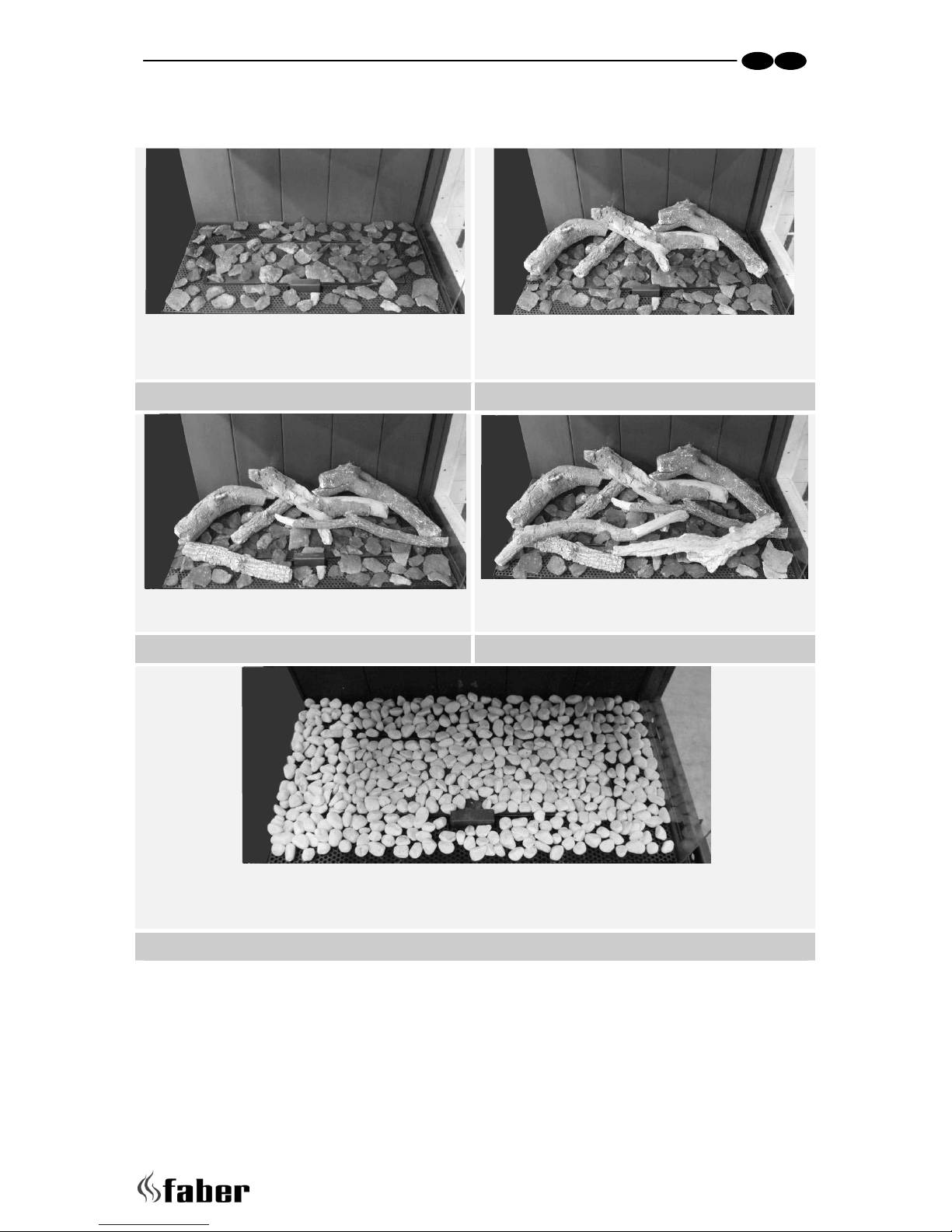
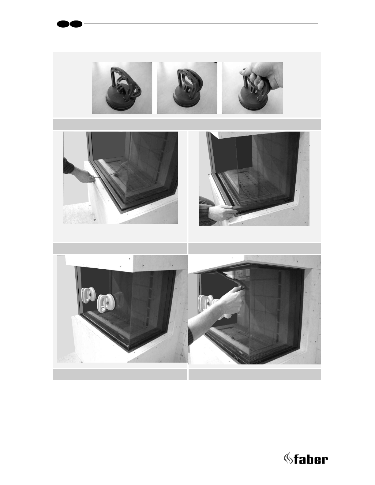
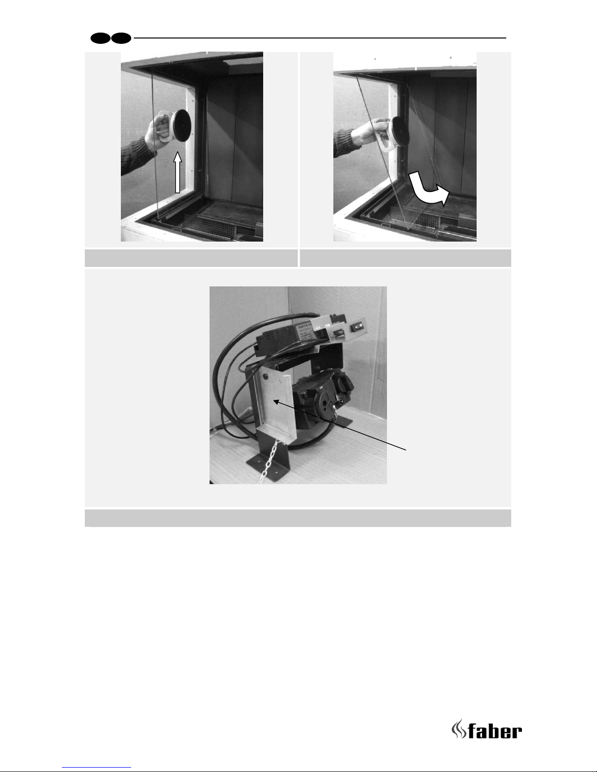
4.4 Removing the glass..........................................................................12
4.5 Placing the appliance.......................................................................13
4.6 Constructing the chimney breast......................................................... 13
4.7 Placing the side glas........................................................................14
4.8 Placing the bottom plate ..................................................................14
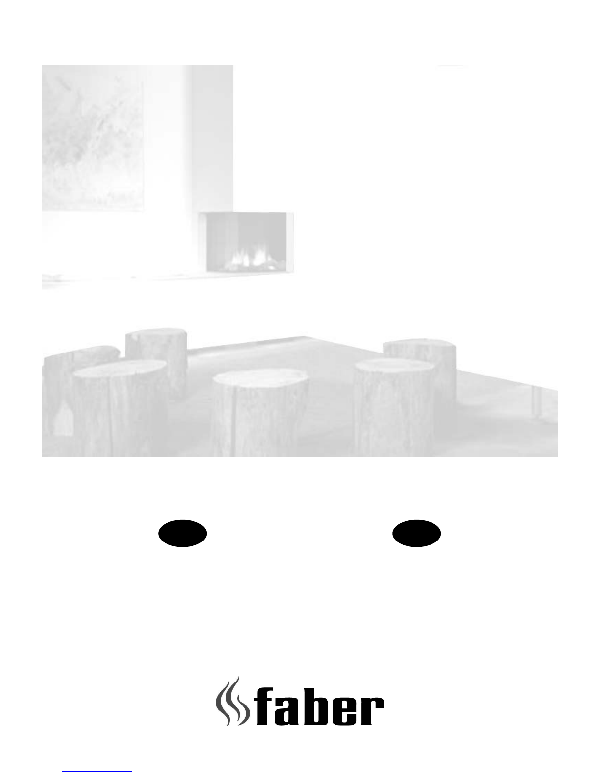
4.9 Placing the pebbles ........................................................................14
4.10 Placing the front glass......................................................................14
5 Commissioning (functional checks) .............................................................15
6 Handing over (final check and customer briefing) ...........................................17
7 Servicing ............................................................................................17
Appendix A: Example calculation..................................................................... 19
Appendix B: Flue restrictor............................................................................20
Appendix C: Installation of the flue..................................................................21
Appendix D: Technical specifications Flatburner ..................................................22
Appendix E: Dimensions Duet R....................................................................... 23
Appendix F: Dimension Duet L ........................................................................24
Appendix G: Dimensions Duet R with floorplate ................................................... 25
Appendix H: Dimensions Duet L with floorplate ...................................................26
Appendix J :Dimensions Convection grid............................................................27
Appendix K : Dimensions Service hatch .............................................................28

7 < < < <
UK IRL
1 Introduction
Note: these instructions should be read carefully and retained for future reference. Please
leave these instructions with the user.
The Duet is available in a left and a right version. According to commonly accepted
definitions in the Fire place business (in front view) the left version has a blinded side at
the right and a right version has a blinded side at the left. See also appendix E, F, G and H.
Before opening the crate always check if the desired version has been delivered!
Special features:
• Room sealed appliance, inlet and outlet are led to the outside using a natural
draught concentric pipe system (100 mm/150 mm) (no power fan required)
• Air supply and flue-gases go to outside atmosphere through wall or roof. A
horizontal extension is possible (see appendix A and B).
• Remote Control is standard.
• This appliance comes standard with two convection grills and one service hatch
• The appliance can be placed in two ways: standing on the floor and hanging on the
wall
• Meets the requirements of the European Gas Appliance Directive (GAD) and carries
the CE mark.

> > > > 8
UK IRL
2 Safety and general information
Before installation, ensure that the local distribution conditions (identification of the type
of gas and pressure) and the adjustment of the appliance are compatible.
This gas appliance is factory set and can not be adjusted.
This appliance does not contain any component manufactured from asbestos or any
asbestos related products.
Ventilation
This appliance is room-sealed and doesn't require purpose provided ventilation.
Never use the appliance if it has a broken glass.
General safety
It is the law in the UK that all gas appliances, are installed by a competent person in
accordance with the Gas Safety (Installation and Use) Regulations (as amended), the
relevant British Standards for Installation work, Building Regulations, Codes of Practice and
the manufacturers instructions.
Always use an additional guard if there are elderly, infirm or children in the same room of
the appliance.
The installation should also be carried out in accordance with the following where
relevant:
• BS5871 Part1
• BS5440 Parts 1 & 2
• BS1251
• Building Regulations Document J (as applicable)
• Building Regulations and Standards issued as relevant by the Department of the
Environment or the Scottish Development Department
• In the Republic of Ireland installation should be carried out in accordance with
IS813, ICP3, IS327, Building Regulations, Codes of Practice, the manufacturers
instructions and all other regulations in force
Failure to comply with the above could leave the installer liable to prosecution and
invalidate the appliance warranty.

9 < < < <
UK IRL
3 Installation requirements
Note: Since the appliance is a source of heat, circulation of air occurs. Therefore it is of
importance that you do not use the appliance shortly after a renovation of the home. Due
to the natural circulation of air, moist and volatile components from paint, building
materials, carpet etc. will be attracted to the lit appliance. These components can settle
onto cold surfaces in the form of soot.
As on all heat producing appliances, soft furnishings such as blown vinyl wallpaper placed
too near the appliance may become scorched or discoloured. This should be born in mind
when installing the appliance.
3.1 Chimney breast
The appliance must be built into a chimney breast. This can be an existing or a new
chimney breast. In either case, take the following points into account:
• The chimney breast must be constructed of an inflammable material.
• Always install the hearth first before constructing the chimney breast.
• Always ventilate the space above the hearth by means of the grates supplied or a
comparable alternative with a minimum air supply of 20000 mm².
• Use special stucco (min. 100°C resistant) or glass fibre wallpaper to prevent
discoloration or tears etc. Recommended drying time:
1 day per mm finishing coat applied.
3.2 Surround with cover plate
• If the cover plate (which can be optionally ordered) is used, the chimney breast
must be placed at the same height as the bottom of the recess. (see figure 1.2).
3.3 Placing the service hatch
• The gas control valve is generally mounted onto the hearth with a brace. Unscrew it
and mount the brace with the gas control valve onto an easily accessible spot
behind the service hatch (max. 1m. from the centre of the hearth in connection
with the length of the flexible gas pipe).
3.4 Flue requirements
• The appliance is of the type C11/C31. The appliance will need to be supplied with
the approved Faber flue pipes and terminal, it is not possible to supply your own.
The minimum effective height of the flue system must be 1 meter.
• Flue routing:
• a horizontal extension with elbows is allowed for a maximum of 4 meters.
• vertical max. 12 meters (without horizontal extensions only)
 Loading...