

Page 1
Instructions Manual
Manuel d’Instructions
Bedienungsanleitung
Manual de instrucciones
Εγχειρίδιο οδηγιών
Руководство по эксплуатации
Gebruiksaanwijzing
Kullanim Kilavuzu
Page 2

2
2
INDEX
SAFETY INFORMATION ......................................................................................................................................................... 4
CHARACTERISTICS ............................................................................................................................................................. 7
INSTALLATION ...................................................................................................................................................................... 8
USE ...................................................................................................................................................................................... 15
CARE AND CLEANING ......................................................................................................................................................... 17
SOMMAIRE
CONSIGNES DE SÉCURITÉ............................................................................................................................................ 20
CARACTERISTIQUES ......................................................................................................................................................... 23
INSTALLATION .................................................................................................................................................................... 24
UTILISATION ....................................................................................................................................................................... 31
NETTOYAGE ET ENTRETIEN .............................................................................................................................................. 33
INHALTSVERZEICHNIS
SICHERHEITSINFORMATIONEN ......................................................................................................................................... 36
CHARAKTERISTIKEN ......................................................................................................................................................... 39
MONTAGE ........................................................................................................................................................................... 40
BEDIENUNG ........................................................................................................................................................................ 47
REINIGUNG UND WARTUNG ............................................................................................................................................... 49
ÍNDICE
INFORMACIÓN DE SEGURIDAD .......................................................................................................................................... 52
CARACTERÍSTICAS ........................................................................................................................................................... 55
INSTALACIÓN ..................................................................................................................................................................... 56
USO ...................................................................................................................................................................................... 63
LIMPIEZA Y MANTENIMIENTO ............................................................................................................................................. 65
ΠΕΡΙΕΧΟΜΕΝΑ
ΣΥΜΒΟΥΛΕΣ ΚΑΙ ΣΥΣΤΑΣΕΙΣ ............................................................................................................................................ 68
ΧΑΡΑΚΤΗΡΙΣΤΙΚΑ ............................................................................................................................................................... 71
ΕΓΚΑΤΑΣΤΑΣΗ .................................................................................................................................................................... 72
ΧΡΗΣΗ ................................................................................................................................................................................. 79
ΚΑΘΑΡΙΣΜΟΣ ΚΑΙ ΣΥΝΤΗΡΗΣΗ ........................................................................................................................................... 81
УКАЗАТЕЛЬ
ИНФОРМАЦИЯ ПО БЕЗОПАСНОСТИ ................................................................................................................................ 84
ХАРАКТЕРИСТИКИ ............................................................................................................................................................ 87
УСТАНОВКА ........................................................................................................................................................................ 88
ЭКСПЛУАТАЦИЯ ................................................................................................................................................................ 95
ОЧИСТКА И ОБСЛУЖИВАНИЕ ........................................................................................................................................... 97
EN
FR
DE
ES
GR
RU
Page 3

3
3
INHOUDSOPGAVE
VEILIGHEIDSINFORMATIE ................................................................................................................................................. 100
EIGENSCHAPPEN ............................................................................................................................................................ 103
INSTALLATIE ..................................................................................................................................................................... 104
GEBRUIK ........................................................................................................................................................................... 111
REINIGING EN ONDERHOUD ............................................................................................................................................ 113
IÇERIKLER
GÜVENLİK HAKKINDA BİLGİLER ....................................................................................................................................... 116
ÖZELLIKLER ...................................................................................................................................................................... 119
MONTAJ ............................................................................................................................................................................. 120
KULLANIM ......................................................................................................................................................................... 127
TEMİZLİK VE BAKIM ........................................................................................................................................................... 129
NL
TR
Page 4
EN
4
4
SAFETY INFORMATION
For your safety and correct operation of the appliance, read this manual
carefully before installation and use. Always keep these instructions
with the appliance even if you move or sell it. Users must fully know the
operation and safety features of the appliance.
The wire connection has to be done by specialized technician.
• The manufacturer will not be held liable for any damages resulting from
incorrect or improper installation.
• The minimum safety distance between the cooker top and the extractor
hood is 650 mm (some models can be installed at a lower height,
please refer to the paragraphs on working dimensions and installation).
• If the instructions for installation for the gas hob specify a greater
distance, this must be respected.
• Check that the mains voltage corresponds to that indicated on the
rating plate fixed to the inside of the hood.
• Means for disconnection must be incorporated in the fixed wiring in
accordance with the wiring rules.
• For Class I appliances, check that the domestic power supply
guarantees adequate earthing.
• Connect the extractor to the exhaust flue through a pipe of minimum
diameter 120 mm. The route of the flue must be as short as possible.
• Regulations concerning the discharge of air have to be fulfilled.
• Do not connect the extractor hood to exhaust ducts carrying
combustion fumes (boilers, fireplaces, etc.).
Page 5
EN
5
5
•
If the extractor is used in conjunction with non-electrical appliances
(e.g. gas burning appliances), a sufficient degree of aeration must be
guaranteed in the room in order to prevent the backflow of exhaust gas.
When the cooker hood is used in conjunction with appliances supplied
with energy other than electric, the negative pressure in the room must
not exceed 0,04 mbar to prevent fumes being drawn back into the room
by the cooker hood.
• The air must not be discharged into a flue that is used for exhausting
fumes from appliances burning gas or other fuels.
• If the supply cord is damaged, it must be replaced from the manufac-
turer or its service agent.
• Connect the plug to a socket complying with current regulations, locat-
ed in an accessible place.
• With regards to the technical and safety measures to be adopted for
fume discharging it is important to closely follow the regulations provided by the local authorities.
WARNING: Before installing the Hood, remove the protective films.
• Use only screws and small parts in support of the hood.
WARNING: Failure to install the screws or fixing device in accordance
with these instructions may result in electrical hazards.
• Do not look directly at the light through optical devices (binoculars,
magnifying glasses…).
• Do not flambè under the range hood; risk of fire.
• This appliance can be used by children aged from 8 years and above
and persons with reduced physical, sensory or mental capabilities or
lack of experience and knowledge if they have been given supervision
or instruction concerning use of the appliance in a safe way and understand the hazards involved. Children shall not play with the appliance.
Cleaning and user maintenance shall not be made by children without
supervision.
• Children should be supervised to ensure that they do not play with the
appliance.
Page 6
EN
6
6
•
The appliance is not to be used by persons (including children) with re-
duced physical, sensory or mental capabilities, or lack of experience
and knowledge, unless they have been given supervision or instruction.
Accessible parts may become hot when used with cooking appliances.
• Clean and/or replace the Filters after the specified time period (Fire
hazard). See paragraph Care and Cleaning.
• There shall be adequate ventilation of the room when the range hood is
used at the same time as appliances burning gas or other fuels (not
applicable to appliances that only discharge the air back into the room).
• The symbol
on the product or on its packaging indicates that this
product may not be treated as household waste. Instead it shall be
handed over to the applicable collection point for the recycling of electrical and electronic equipment. By ensuring this product is disposed of
correctly, you will help prevent potential negative consequences for the
environment and human health, which could otherwise be caused by
inappropriate waste handling of this product. For more detailed information about recycling of this product, please contact your local city office, your household waste disposal service or the shop where you purchased the product.
Page 7
EN
7
7
CHARACTERISTICS
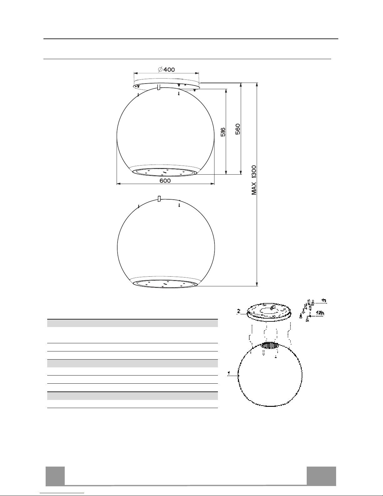
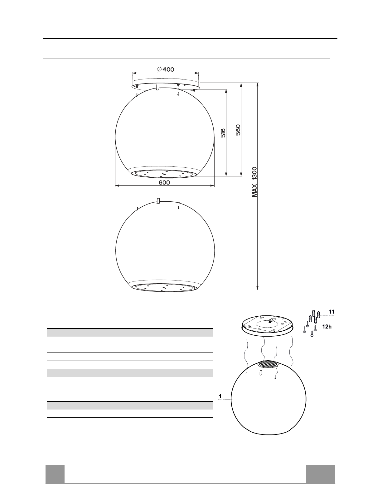
Dimensions
Components
Ref. Q.ty Product Components
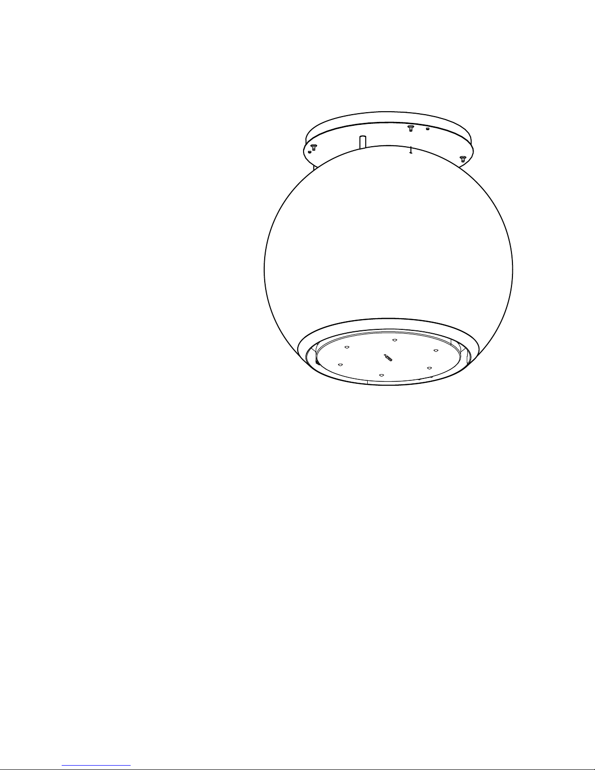
1 1 Hood Canopy complete with: Controls, Light, Filters,
Motor.
2 1 Hood support plate.
Ref. Q.ty Installation Components
11 4 Wall plugs ø 10
12h 4 Screws 4.2 x 44.4
Q.ty Documentation
1 Instruction Manual
Page 8
EN
8
8
INSTALLATION
This hood is designed to be mounted on the ceiling/on a shelf, above a free-standing Hob (min. 650
mm), in:
• Recirculation version: Internal recirculation.
Sequence of operations - Installation
• Preparing for installation
• Drilling the Ceiling/Shelf and Fixing the support plate
• Connections
• Fitting the hood body
• Functional Check
• Disposal of Packaging
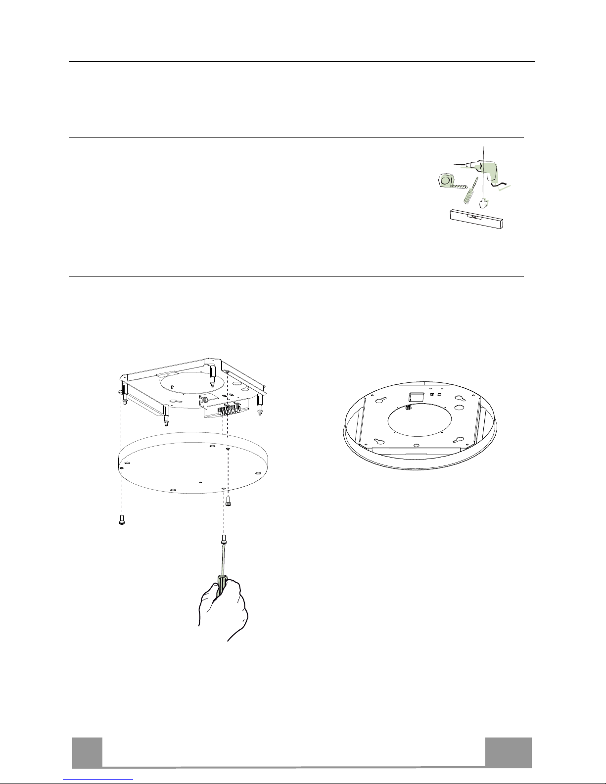
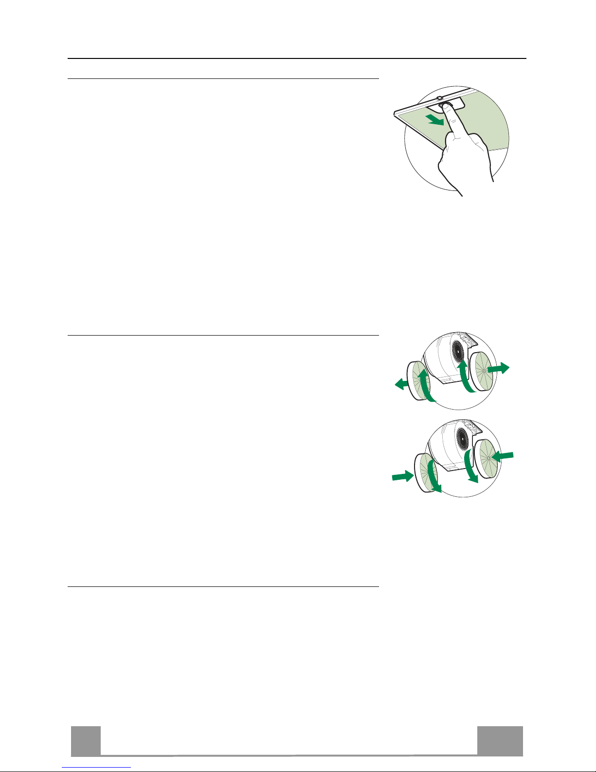
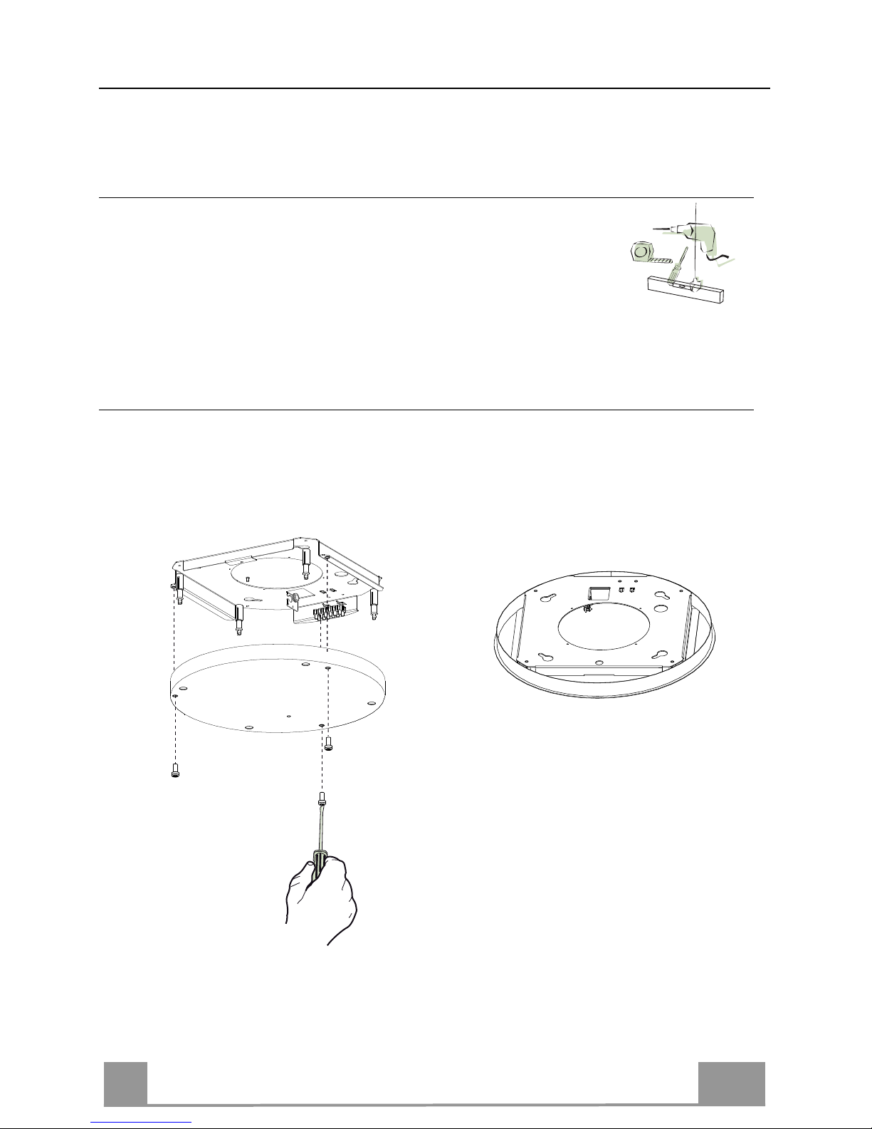
Opening Plate and preparing for assembly
• Unfasten the screws joining the plate to its cover.
• Take the plate and position it in the correct direction, as shown in the figure.
Page 9

EN
9
9
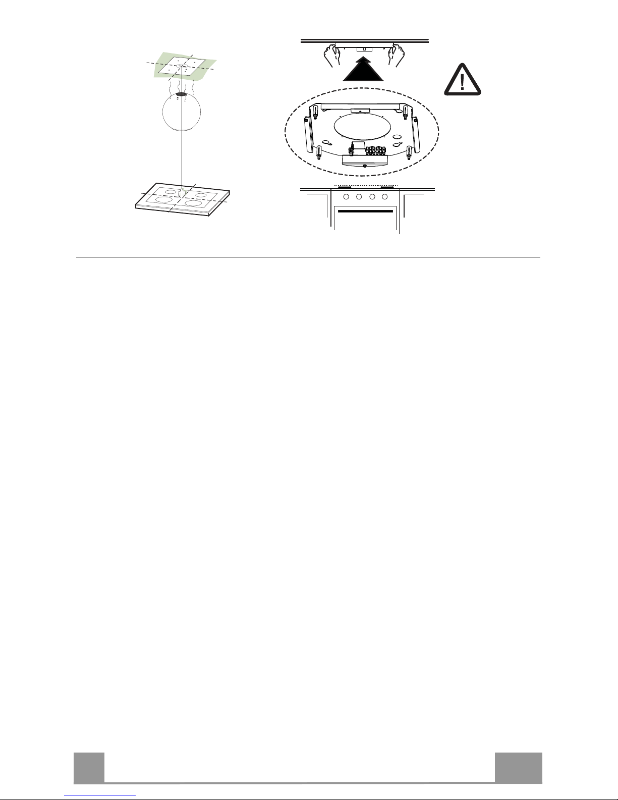
Ceiling/Shelf drilling and Plate Fixing
CEILING/SHELF DRILLING
• Use a plumb-line and mark the centre of the cooking hob on the Support Ceiling/Shelf
• Rest the Plate against the Ceiling/Shelf, making sure it is the right way up, as shown in the
figure.
• Mark the centres of the holes in the plate.
• Drill the following points:
• Ceilings in solid concrete: As per concrete plugs used.
• Ceilings in hollow bricks with 20 mm resistance thickness: Drill a hole ø 10 mm (insert
Plugs 11 supplied immediately).
• Ceilings with Wood Beams: As per Wood Screws used (not supplied).
• Wooden shelf, with a resistant thickness of 15 mm: drill a hole ø 7 mm.
• Feeding the electric supply cable: drill a hole ø 10 mm.
• Insert two screws, crossing them and leaving 4-5 mm from the ceiling:
• for solid concrete, concrete plugs, not provided.
• for hollow bricks with approx. 20 mm resistance thickness, screws 12h, provided.
• for wooden beams, wood screws, not provided.
• for wooden shelves, screws with washers and nuts, not provided.
Page 10
EN
1
10
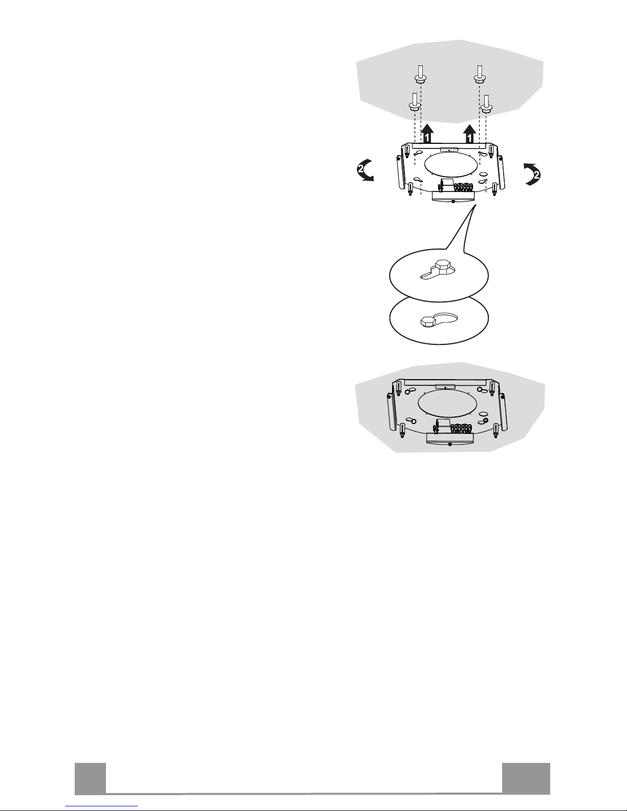
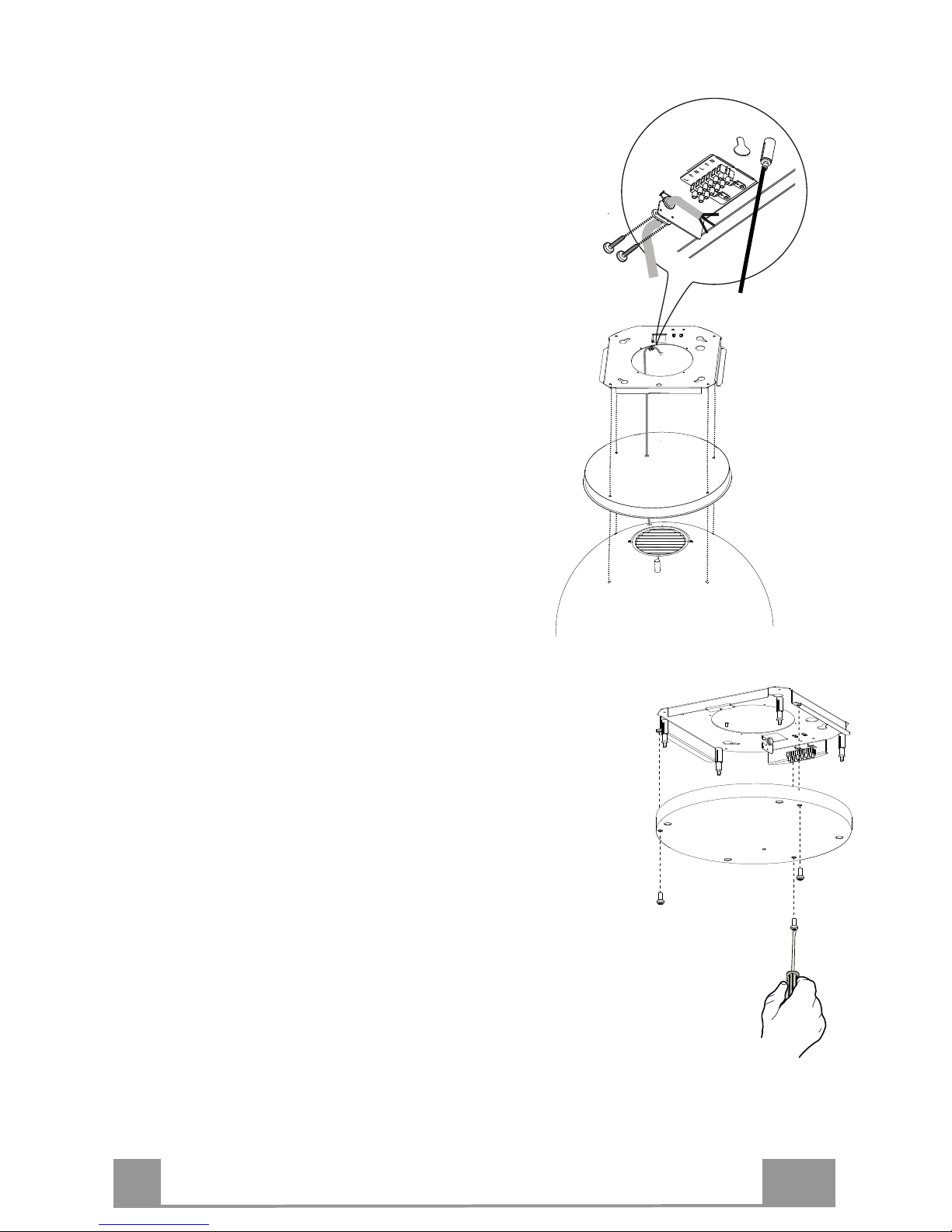
FIXING THE PLATE
• Lift up the Fixing plate and fit the slots onto the two
screws previously inserted in the ceiling, and turn until they are at the centre of the adjustment slot.
Warning: The plate must be facing in the direction
shown in the figure
• Tighten the two screws completely and screw in the
other two provided; before locking the screws
completely it is possible to make adjustments by
turning the piece, making sure that the screws do not
come out of the adjustment slot.
• The unit must be securely fastened both due to the
weight of the Hood and the stress caused by
occasional sideways pressure on the Appliance when
in position. Once the unit has been fixed, make sure
that the plate is stable.
• In all cases where the Ceiling is not sufficiently
strong at the point of suspension, the Installation
technician must strengthen it with suitable plates and
counterplates, anchored to structurally sound
elements.
• Check that the plate is level on the ceiling.
Page 11
EN
1
11
CONNECTING HOOD-PLATE CABLES
N.B. Before proceeding with installation the Hood must be raised to a height of at least
650 mm above the cooker hob by means of a support or with the assistance of another
person. Take care not to exceed the maximum hood extension indicated in the dimensional
drawing.
This operation is essential, as the Hood Cables are to be connected to the Plate mounted
on the ceiling, and this must be done without the weight of the Hood bearing down on
the structure.
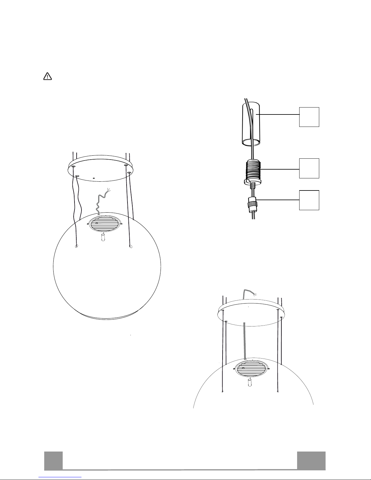
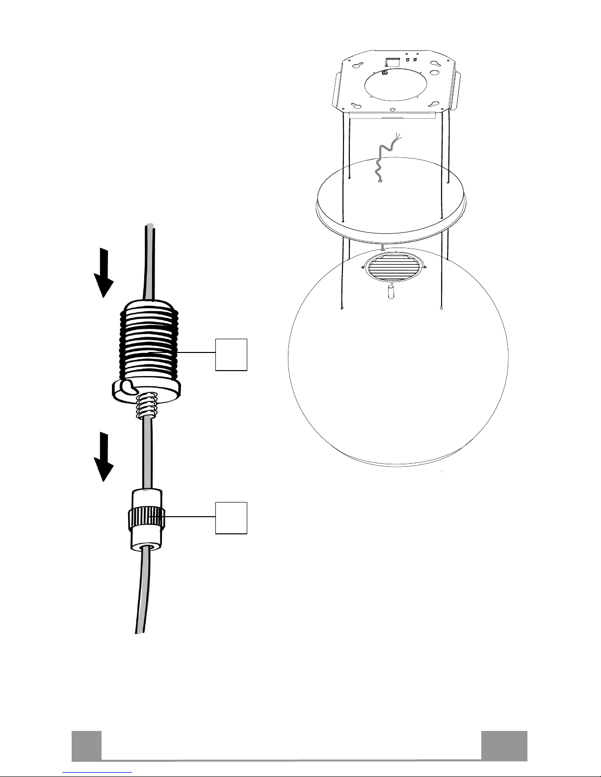
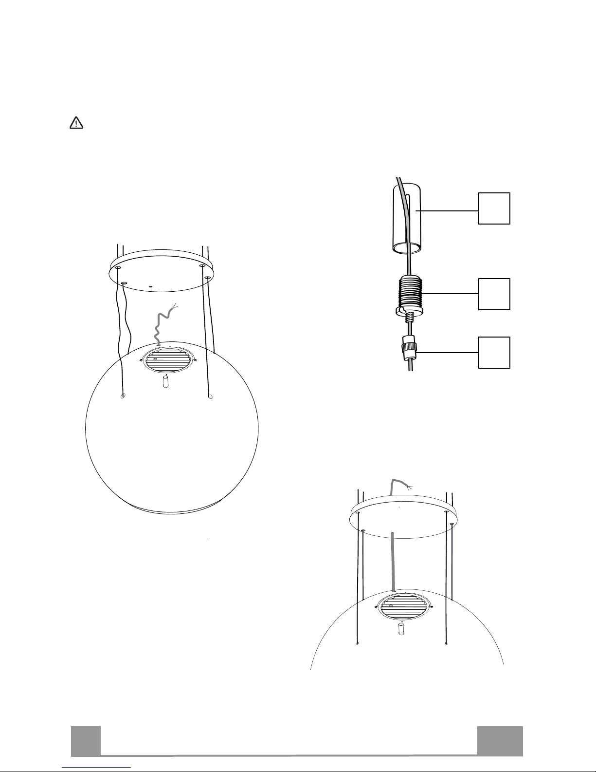
The system used to fix the 4 Cables comprises 3 components:
• Threaded pawl (a) already mounted on the ceiling Plate.
• Cable locking screw (b), provided.
• Safety knob (c), provided.
• Pass the 4 cables (connected to the
hood canopy) through the respective
holes in the plate cover, after opening it
as above, making sure that it faces in
the same direction as the plate
connected to the ceiling.
• Insert the hood power supply cable into the
hole provided in the cover.
Warning: Do not break or remove the tie
that fixes the power supply cable to the hood
a
b
c
Page 12
EN
1
12
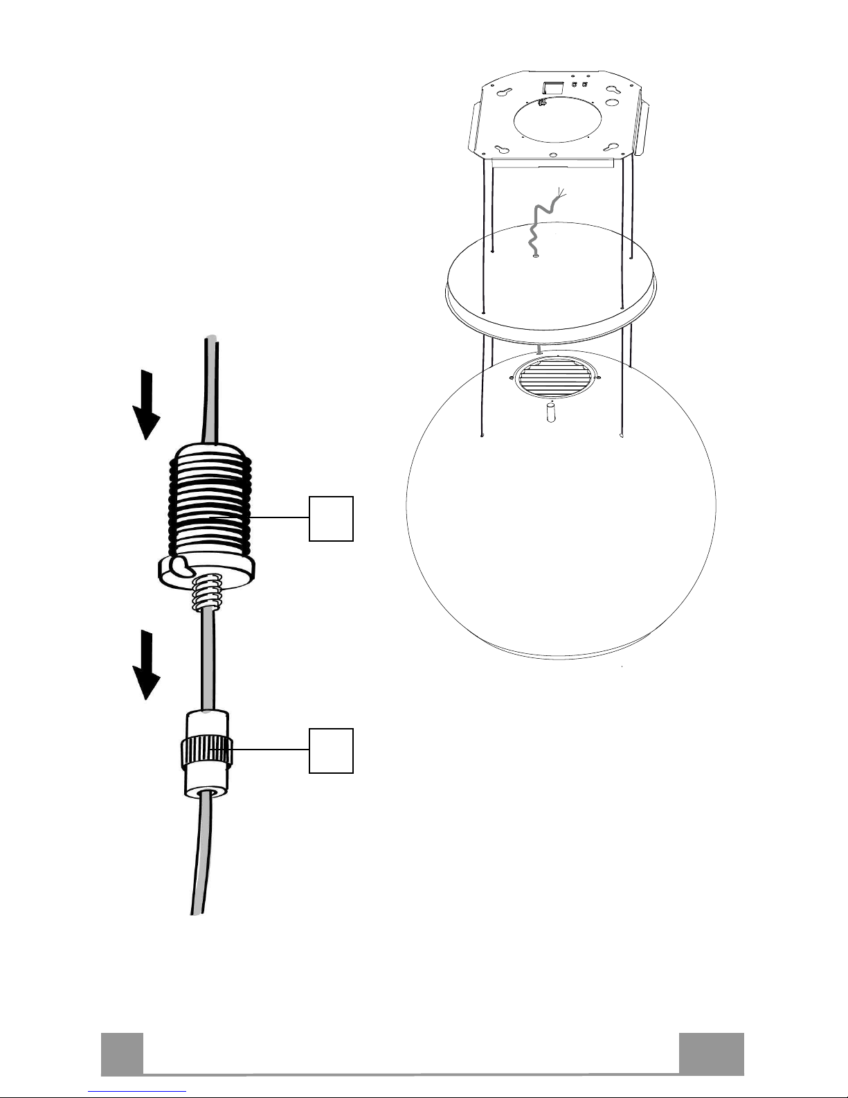
• Pay attention to the direction of the plate
fixed to the ceiling (the plate limit pawl has
a corresponding hole on the plate cover and
on the hood canopy).
• Insert the safety knobs (c) into the
respective cables, with the thread to the
top.
• Insert the cable locking screws (b) into
the respective cables.
c
b
Page 13
EN
1
13
• Pass the Cables into the slots on the threaded pawls
(a) and tighten the cable locking screws (b) into the
pawls themselves.
• When the operation has been
completed, the result should be as
shown in the figure for all 4
cables.
• At this point, all 4 cables are now
connected to the Plate.
Tension the Cables by pushing them
upwards, so that they slide inside the
cable locking screw and out through the
slot in the threaded pawl.
This is possible because the cable
locking screw involves a system that
allows the Cable to slide in one direction
only, preventing it from sliding in the
other direction.
Make sure that the cables are all the
same length, to facilitate final levelling
operations, and that the front left cable
is not slacker than the others.
Page 14

EN
1
14
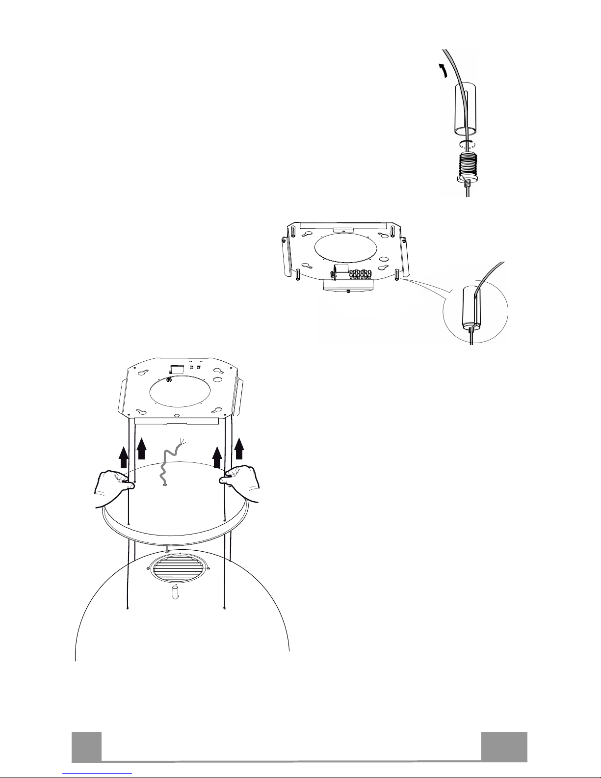
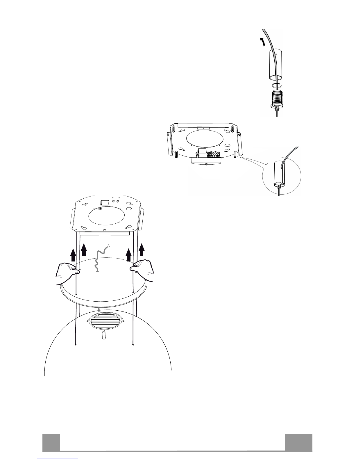
FIXING THE POWER SUPPLY CABLE
• Tighten the power supply cable and
fix it to the bracket on the ceilingmounted plate, using the tongue
already mounted and 2 screws.
• Slot the rubber cable raceway already
threaded onto the power cable into the
slot to prevent future damage.
• Connect the Hood to the Mains Power
Supply, inserting a bipolar switch
with a contact aperture of at least 3
mm.
• Remove the Grease filters (see
paragraph “Maintenance”) and make
sure that the Power cable connector
has been properly inserted into the
Suction fan socket.
• At this point it is possible to remove
the tie fixing the power supply cable
to the hood canopy.
FITTING THE PLATE COVER
• Screw the cover back onto the plate
using the screws removed as
described above.
AIR OUTLET – RECIRCULATION VERSION
• Open the lighting unit by pulling on the notch provided.
• Remove the grease filter.
• Make sure that the Activated charcoal odour filter has been fitted.
Page 15
EN
1
15
USE
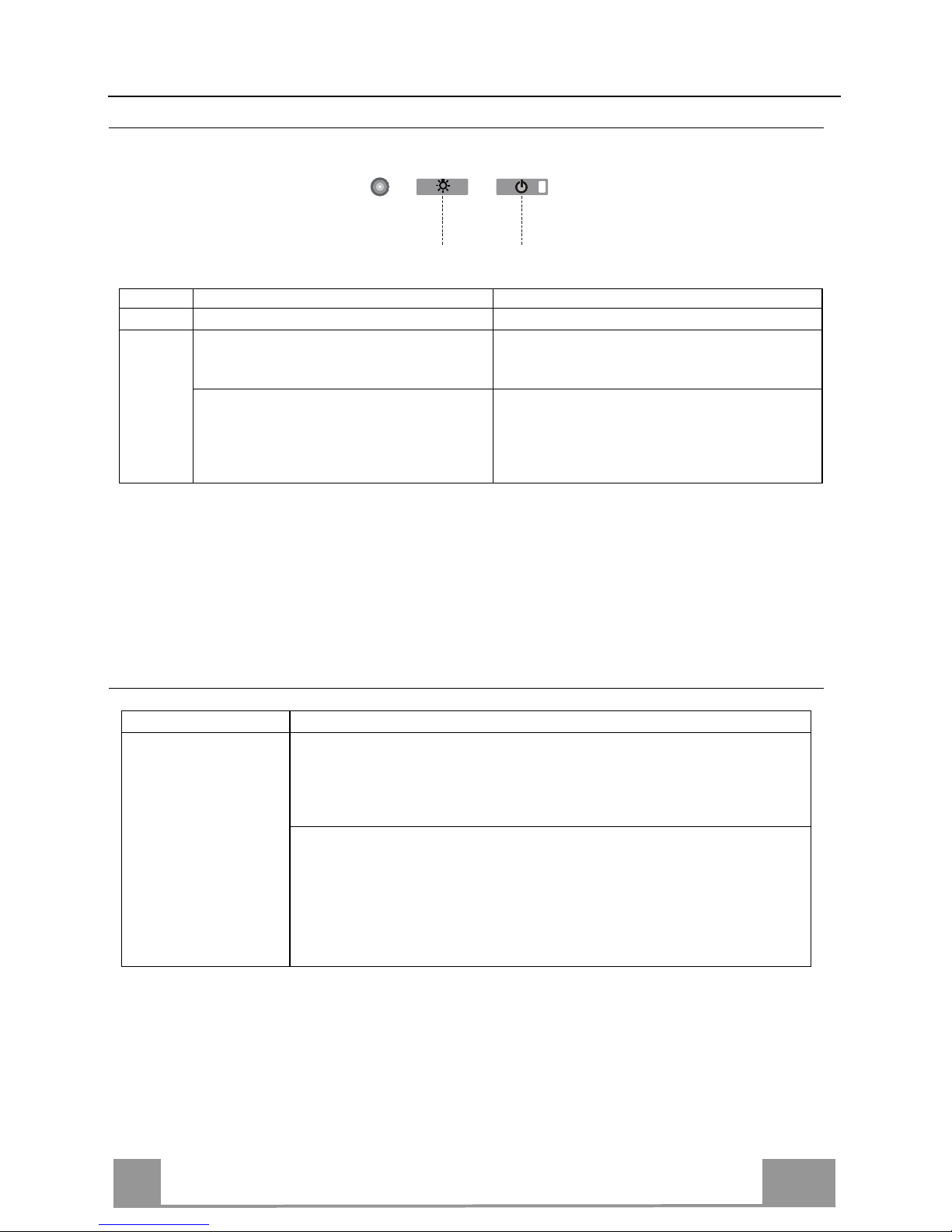
Control panel
L T1
Button
Function
Display
L
Turns the lights On/Off.
-
T1 Hood Down
Press for 2 seconds to raise the Hood.
Press briefly to turn the Motor On/Off.
On/Off
Hood Up
Press once: The Hood lowers.
Press a second time: The Hood Stops.
When the movement has been completed
the motor turns on at Speed two.
Off/Off
The electronic control system recognises and signals two types of fault.
Led T1
Slow flashing
Current absorption threshold exceeded:
If an overload condition occurs, the fault is signalled by LED T1 on the
keyboard flashing once every 2 seconds. Check that nothing is blocking
normal hood movements.
The signal remains active until a new hood open/close command is given.
Rapid flashing
Hood opening safety microswitch tripped:
If the safety microswitch trips, the fault is signalled by LED T1 on the
keyboard flashing quickly (once every 250 ms). This means that the hood
has passed the microswitch…….. Call Technical Assistance!
You can continue to use the hood’s light and motor functions while this
fault is active. Whenever the motor is on, LED T1 will continue to flash,
indicating that the fault is still present.
Page 16
EN
1
16
REMOTE CONTROL
This appliance can be commanded using a remote control, powered by
a CR2032 type 3 V battery (not supplied).
• Do not place the remote control near heat sources.
• Do not discard the batteries with normal waste, they must be put
into the specific containers.
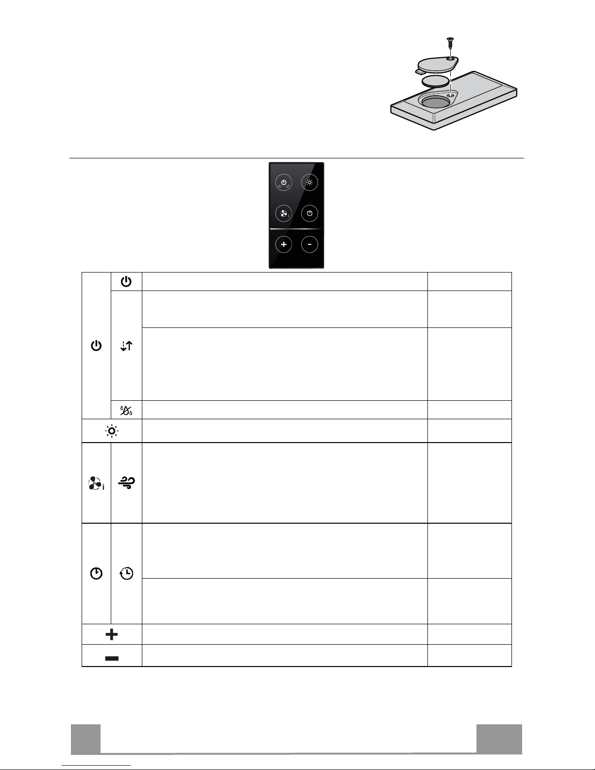
Control panel
Turns the Motor On/Off.
-
Hood Closed
:
- Press the button briefly to start lowering the hood
- It will stop when the button is pressed again.
When the movement has been completed the motor will start at speed 2.
-
Hood Open
:
- Press and hold for 2 seconds to activate raising of the hood, which
stops when it reaches the stop.
- Press (briefly) to stop the movement (before the stop is reached).
- Press again briefly to turn the motor on/off.
- Press and hold for 2 seconds to start raising of the hood.
- If the motor is on, it will first stop the motor and then start the
movement.
-
-
Turns the Hood lights On/Off.
-
INTENSIV
E
- This can only be activated with the hood lowered and when the delay
or 24h functions are not active.
- Activates Intensive speed from any other speed.
To disable it, simply press the same button again or turn the motor off.
- Intensive speed is timed to run for 6 minutes. At the end of the 6
minutes the system will automatically return to the speed that was set
before.
The led on the
motor button (on
the hood controls) will flash
once a second.
Press briefly for the Delay Function
:
Can only be activated if the Intensive or 24h function is not active.
Activates and deactivates total shutdown of the hood (motor+lights)
after 30 minutes:
To disable the Delay, simply press the button again or turn the motor
off.
The led on the
motor button (on
the hood controls)
will flash once
every 0.5 seconds.
Press and hold for 2 sec. for the 24H Function:
Can only be activated if the Intensive or Delay function is not active.
Activates and deactivates the 24H function for 10 minutes every hour,
for 24 hours. After this time it is deactivated.
The led on the
motor button (on
the hood controls)
will flash once
every 2 seconds.
Increases the speed of the Motor.
-
Decreases the speed of the Motor.
-
Page 17
EN
1
17
CARE AND CLEANING
Grease filter
The filter must be cleaned every 2 months of operation, or more
frequently for particularly heavy usage, and can be washed in a
dishwasher.
CLEANING METAL SELF- SUPPORTING GREASE FILTER
• Open the lighting unit by pulling on the nocth.
• Remove the filter one by one pushing it towards the back side
of the hood unit and simultaneously pulling downwards.
• Any kind of bending of the filter has to be avoided when washing it. Before fitting it again into the hood make sure that it is
completely dry.
• When fitting the filter into the hood pay attention that they are
mounted in correct position the handle facing outwards.
• Replace the lighting unit.
Activated Charcoal Filter (Recirculation Version)
This cannot be washed or regenerated, and must be changed approximately once every 4 months, or more frequently in the case
of particularly intensive use.
CHANGING
• Open the light unit.
• Remove grease filter.
• Remove the saturated Activated Charcoal Filters, as indicated
(A).
• Fit the new Filters, as indicated (B).
• Fit the anti-grease filter and the Light Unit back into position.
A
B
Lighting unit
• For replacement contact technical support ("To purchase
contact technical support").
Page 18
EN
1
18
Additional information for the installation technician
Hood canopy lighting
It is possible to adjust the colour and intensity of the hood canopy lighting
• Open the lighting unit by pulling on the notch provided.
• Adjust the lighting, using the buttons on button pad B, following the indications provided on
the label
C
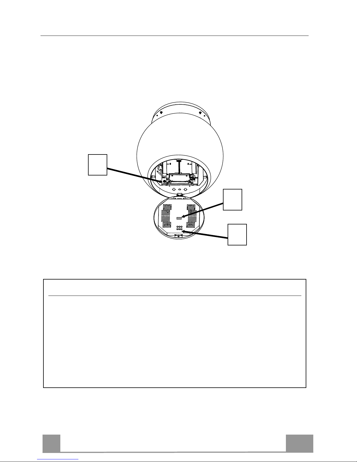
Procedure to be used in case of malfunction on the movement
• Check that the fuse is properly inserted and that it has not burned out, for replacing the
fuse open the lighting unit and unscrew the fuser holder and replace it with one having
the same characteristics (Rif.A)
• Check that the hood canopy is fitted level.
• Check that the four cables are all at the same tension.
If even these operations do not solve the problem contact the Technical Assistance.
A
B
C
Page 19
EN
1
19
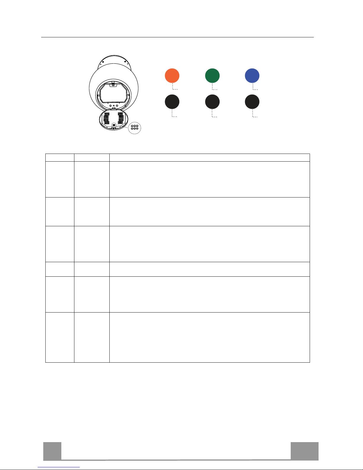
Adjusting Hood canopy lighting
Button Colour
Function
1
Red
Manages the intensity of the colour Red.
Press and hold the button to increase or decrease the intensity each time you
press.
The maximum and minimum intensity limits are marked by a brief flash of
the selected colour on the lamp.
2
Black
Manages the speed at which colours change when both the programs for
Button 4 are used. The speed increases or decreases each time it is pressed.
The decrease is indicated by a brief flash.
They are disabled by pressing Button 6.
3
Green
Manages the intensity of the colour Green.
Press and hold the button to increase or decrease the intensity each time you
press.
The maximum and minimum intensity limits are marked by a brief flash of
the selected colour on the lamp.
4
Black
Manages the 2 colour change programs: Blended or Intermittent.
They are disabled by pressing Button 6.
5
Blue
Manages the intensity of the colour Blue.
Press and hold the button to increase or decrease the intensity each time you
press.
The maximum and minimum intensity limits are marked by a brief flash of
the selected colour on the lamp.
6
Black
Light On / Off
Initially when turned On the colour of the Hood is White. It can be modified
as desired by increasing or decreasing the intensity of colours using the
buttons (1-3-5). To return to the original state simply increase the intensity
of all 3 colours to maximum using the buttons (1-3-5).
The current colour setting can be stored by pressing and holding the button
for 3 seconds.
1
2
3
4
5
6
Page 20
FR
2
20
CONSIGNES DE SÉCURITÉ
Pour votre sécurité et pour garantir le fonctionnement correct de
l’appareil, veuillez lire attentivement ce manuel avant d’installer et de
mettre en fonction l’appareil. Toujours conserver ces instructions avec
l’appareil, même en cas de cession ou de transfert à une autre personne.
Il est important que les utilisateurs connaissent toutes les caractéristiques
de fonctionnement et de sécurité de l’appareil.
La connexion des câbles doit être effectuée par un technicien compétent.
• En aucun cas le fabricant ne peut être tenu pour responsable d’éventuels
dommages dus à une installation ou à une utilisation impropre.
• La distance de sécurité minimum entre le plan de cuis
son et la hotte
aspirante est de 650 mm (certains modèles peuvent être installés à une
hauteur inférieure ; voir le paragraphe concernant les dimensions de travail
et l’installation).
• Si les instructions d’installation du plan de cuisson à gaz spécifient une
distance supérieure à celle indiquée ci-dessus, veuillez impérativement en
tenir compte.
• Assurez-vous que la tension du secteur correspond à celle indiquée sur la
plaque des caractéristiques apposée à l’intérieur de la hotte.
• Les dispositifs de sectionnement doivent être montés dans l’installation fixe
conformément aux normes sur les systèmes de câblage.
• Pour les appareils de Classe I, s’assurer que l’installation électrique de
votre intérieur dispose d’une mise à la terre adéquate.
• Reliez l’aspirateur du conduit de cheminée avec un tube ayant un diamètre
minimum de 120 mm. Le parcours des fumées doit être le plus court
possible.
• Respecter toutes les normes concernant l’évacuation de l’air.
• Ne reliez pas la hotte aspirante aux conduits de chem
inée qui acheminent
les fumées de combustion (par ex. de chaudières, de cheminées, etc.).
Page 21
FR
2
21
•
Si vous utilisez l’aspirateur en même temps que des appareils non électriques
(par ex. fonctionnant au gaz), veillez à ce que la pièce soit adéquatement
ventilée, afin d’empêcher le r
etour du flux des gaz d’évacuation. Si vous utilisez
la hotte de cuisine en même temps que des appareils non alimentés à
l’électricité, la pression négative dans la pièce ne doit pas dépasser 0,04 mbar,
afin d’éviter que les fumées soient réaspirées dans la pièce où se trouve la
hotte.
• Ne pas évacuer l’air à travers une conduite utilisée pour l’évacuation des
fumées des appareils de combustion alimentés au gaz ou avec d’autres
combustibles.
• Si le cordon d’alimentation est endommagé, faites-le remplacer par
le fabricant
ou par un technicien d’un service après-vente agréé.
• Branchez la fiche à une prise conforme aux normes en vigueur et dans une
position accessible.
• En ce qui concerne les dimensions techniques et de s
écurité à adopter pour
l’évacuation des fumées, veuillez vous conformer scrupuleusement aux
règlements établis par les autorités locales.
AVERTISSEMENT : Avant d’installer la hotte, retirer les films de protection.
•
Utilisez exclusivement des vis et des petites fournitures du type adapté pour la
hotte.
AVERTISSEMENT toute installation de vis et de dispositifs de fixation non
conformes à ces instructions peut entraîner des risques de décharges
électriques.
•
Ne pas observer directement avec des instruments optiques (jumelles, lentilles
grossissantes...).
• Ne flambez pas des mets sous la hotte
: sous risque de développer un incendie.
• Cet appareil peut être utilisé par des enfants de plus de 8 ans et par des
personnes dont les capacités physiques, sensorielles ou mentales sont
diminuées ou ayant une exp
érience et des connaissances insuffisantes, pourvu
que ce soit sous la surveillance attentive d’une personne responsable et après
avoir reçu des instructions sur la manière d’utiliser cet appareil en toute sécurité
et sur les dangers que cela comporte. Assurez-
vous que les enfants ne jouent
pas avec cet appareil. Le nettoyage et l’entretien de la part de l’utilisateur ne
doivent pas être effectués par des enfants, à moins qu’ils ne soient surveillés.
• Surveillez les enfants. S’assurer qu’ils ne jouent pas avec l’appareil.
Page 22
FR
2
22
•
Cet appareil n’est pas destiné à être utilisé par des personnes (enfants
compris) dont les capacités physiques, sensorielles ou mentales sont
diminuées ou ayant une expérience et des connaissances insuffisantes, à
moins que celles-ci ne soient attentivement surveillées et instruites.
Les parties accessibles peuvent devenir très chaudes durant l’utilisation
des appareils de cuisson.
• Nettoyer et/ou remplacer les filtres après le délai indiqué (danger
d’incendie). Voir le paragraphe Nettoyage et Entretien.
• Veillez à ce que la pièce bénéficie d’une ventilation adéquate lorsque la
hotte fonctionne en même temps que des appareils utilisant du gaz ou
d’autres combustibles (non applicable aux appareils qui évacuent l’air
uniquement dans la pièce).
• Le symbole marqué sur le produit ou sur son emballage indique que ce
produit ne peut pas être éliminé comme déchet ménager normal. Lorsque
ce produit doit être éliminé, veuillez le remettre à un centre de collecte
prévu pour le recyclage du matériel électrique et électronique. En vous
assurant que cet appareil est éliminé correctement, vous participez à
prévenir des conséquences potentiellement négatives pour l'environnement
et pour la santé, qui risqueraient de se présenter en cas d’élimination
inappropriée. Pour toute information supplémentaire sur le recyclage de ce
produit, contactez votre municipalité, votre déchetterie locale ou le magasin
où vous avez acheté ce produit.
Page 23
FR
2
23
CARACTERISTIQUES
Encombrement
Composants
Réf. Q.té Composants du produit
1 1 Corps de hotte équipé de : commandes, lumière,
filtres, moteur.
2 1 Plaque support hotte
Réf. Q.té Composants de l’installation
11 4 Chevilles ø 10
12h 4 Vis 4,2 x 44,4
Q.té Documentation
1 Manuel d’instructions
2
Page 24
FR
2
24
INSTALLATION
Cette hotte est prévue pour être installée au plafond/étagère, au-dessus (650 mm min.) d’un plan de
cuisson en îlot en :
• Version filtrante Recirculation intérieure.
Séquence opérations d’installation
• Préparation à l’installation
• Perçage plafond/étagère et fixation plaque de support
• Connexions
• Montage du corps de hotte
• Contrôle fonctionnel
• Élimination des emballages
Ouverture de la plaque et préparation à son montage
• Desserrer les vis qui unissent la plaque à son couvercle.
• Prendre la plaque et la placer dans le sens correct comme indiqué dans la figure.
Page 25
FR
2
25
Perçage plafond/étagère et fixation plaque
PERÇAGE PLAFOND/ÉTAGÈRE
• À l’aide d’un fil à plomb, ramener sur le plafond/étagère de support le centre du plan de
cuisson.
• Appuyer la plaque au plafond/étagère en veillant de la positionner dans le bon sens, comme
indiqué dans la figure.
• Marquer les centres des trous de la plaque.
• Percer les points suivants :
• Plafond en béton massif : selon les chevilles pour béton employées.
• Plafond en béton et chambre à air, avec une épaisseur résistante de 20 mm : percer ø 10
mm (insérer tout de suite les chevilles 11 fournies).
• Plafond en poutres de bois : selon les vis pour bois employées (non fournies).
• Étagère en bois, avec une épaisseur résistante de 15 mm : percer ø 7 mm.
• Passage du câble électrique d’alimentation : percer ø 10 mm.
• Serrer en diagonale et en laissant 4-5 mm du plafond les deux vis :
• pour béton massif, les chevilles pour béton, non fournies.
• pour béton avec chambre à air, avec une épaisseur résistante d’environ 20 mm, vis 12h
fournies.
• pour poutres de bois, vis pour bois, non fournies.
• pour étagère de bois, vis avec rondelles et écrous non fournies.
Page 26

FR
2
26
IXATION PLAQUE
• Soulever la plaque de fixation, emboîter les trous sur
les deux vis précédemment prévues au plafond et
tourner jusqu’au centre du trou de réglage.
Attention : Le sens de la plaque doit être celui indiqué
dans la figure.
• Serrer les deux vis et visser les deux autres fournies ;
avant de serrer définitivement les vis vous pouvez
effectuer des réglages en tournant la pièce, en faisant
attention à ce que les vis ne sortent pas du siège du
trou de réglage.
• La fixation doit être sûre, aussi bien par rapport au
poids de la hotte qu’aux contraintes provoquées par
des poussées latérales occasionnelles à l’appareil
monté. À la fin de la fixation, vérifier que la plaque
est stable.
• Au cas où le plafond ne serait pas suffisamment
robuste dans le point de suspension, l’installateur
devra le renforcer à l’aide de plaques et de contreplaques opportunes ancrées sur des parties
structurellement résistantes.
• Vérifier le nivellement de la plaque au plafond.
Page 27
FR
2
27
NNEXION CÂBLES HOTTE-PLAQUE
N.B. Avant de commencer l’installation, il est nécessaire d’amener la hotte à une hauteur
d'au moins 650 mm du plan de cuisson, avec un support ou en se faisant aider par une autre
personne. Prendre garde de ne pas dépasser la cote maximum d’extension de la hotte indiquée dans le dessin dimensionnel.
Cette mesure est fondamentale, puisque les câbles de la hotte devant être branchés à la
plaque montée au plafond, il est impératif d’éviter que le poids de la hotte puisse peser
sur la structure.
Le système de fixation des 4 câbles est formé de 3 parties :
• Cliquet fileté (a) déjà monté sur la plaque de plafond.
• Vis serre-câble (b) fournie.
• Pommeau de sécurité (c) fourni.
•
Passer les 4 câbles (accrochés au corps
de hotte) dans les trous correspondants
du couvercle de la hotte, précédemment
déposé, en veillant à ce que le sens soit
le même que celui de la plaque
accrochée au plafond.
• Insérer le câble d’alimentation de la hotte dans
le trou prévu sur le couvercle.
Attention : ne pas casser ni retirer le collier
qui fixe le câble d’alimentation de la hotte.
a
b
c
Page 28
FR
2
28
• Faire attention au sens d’orientation de la
plaque fixée au plafond (le cliquet de fin de
course de la plaque présente son trou correspondant sur le couvercle de la plaque et
sur le corps de hotte).
•
Enfiler les pommeaux de sécurité (c)
dans leurs câbles correspondants, en
veillant à ce que le filetage soit orienté
vers le haut.
• Enfiler les vis serre-câble (b) dans leurs
câbles respectifs.
B
C
Page 29
FR
2
29
• Faire passer les câbles dans les trous des cliquets filetés (a) et serrer les vis serre-câble (b) à ces mêmes cliquets.
• À la fin de l’opération, le résultat
doit être celui représenté dans la
figure pour tous les 4 câbles.
• À ce point, les 4 câbles sont reliés à la
p
laque.
Mettre les câbles sous tension en les
poussant vers le haut de manière à ce
qu’ils coulissent dans la vis serre-câble
et hors du trou du cliquet fileté.
Cela est possible, car le système présent
dans la vis serre-câble permet au câble
de coulisser dans un seul sens à son
intérieur, en bloquant le coulissement
dans l’autre sens.
Veiller à ce que les câbles aient tous la
même longueur pour faciliter
l’opération de nivellement final. Faire
attention à ce que le câble avant gauche
ne soit pas plus mou que les autres.
Page 30
FR
3
30
FIXATION DU CÂBLE D’ALIMENTATION
• Tendre le câble d’alimentation et le fixer à la bride
sur la plaque de plafond en utilisant la languette
déjà montée avec 2 vis.
• Emboîter le passe-câble en caoutchouc déjà enfilé sur le câble d’alimentation dans le trou pour
éviter tout endommagement futur.
• Brancher la hotte à l’alimentation de
secteur en intercalant un interrupteur
bipolaire ayant une ouverture des
contacts d’au moins 3 mm.
• Retirer les filtres à graisse (voir par.
« Entretien ») et s’assurer que le
connecteur du câble d’alimentation est
correctement branché dans la prise de
l’aspirateur.
• À ce point, vous pouvez couper le
collier qui bloque le câble
d’alimentation au corps de hotte.
MONTAGE DU COUVERCLE DE LA PLAQUE
•
À l’aide des vis précédemment retirées, resserrer
le couvercle à la plaque.
SORTIE DE L’AIR VERSION FILTRANTE
• Ouvrir le groupe d’éclairage en le tirant sur l’encoche prévue à cet effet.
• Retirer le filtre à graisse.
• S’assurer de la présence des filtres anti-odeur à charbon actif.
Page 31

FR
3
31
UTILISATION
Tableau des commandes
L T1
Touche Fonction Affichage
L Allume/Éteint les lumières -
T1 Hotte basse
Appuyer pendant 2 secondes pour remonter la
hotte.
Appui bref On/Off moteur
Branché/Débranché
Hotte haute
Premier appui : La hotte descend.
Deuxième appui : Stop hotte.
À la fin du mouvement, le moteur se branche à
la deuxième vitesse.
Débranché/Débranché
L’électronique reconnaît deux types d’anomalies et donne le signal correspondant
Led T1
Clignotement lent
Dépassement du seuil d’absorption de courant:
En présence d'une condition de surcharge, l'anomalie est signalée par le
clignotement, toutes les 2 secondes, de la led T1 située sur le clavier.
Vérifier l’absence de tout empêchement durant le mouvement de la hotte.
Ce signalement demeure actif jusqu’à ce qu’une nouvelle commande
d’ouverture/fermeture de la hotte soit donnée.
Clignotement rapide
Intervention du microswitch de sécurité en ouverture:
En cas d’intervention du microswitch de sécurité, l’anomalie est signalée
par le clignotement rapide de la led T1 (toutes les 250ms), indiquant que la
hotte a dépassé le fin de course…….. Contacter le service après vente!
En présence de cette anomalie, l’accès aux fonctions de la hotte (lumières et
moteur) est toujours possible. Si le moteur est branché, la led T1 continuera
à clignoter, signalant que l’anomalie est toujours présente.
Page 32

FR
3
32
TÉLÉCOMMANDE
Cet appareil peut être commandé via une télécommande, alimentée
avec une batterie 3 V type CR2032 (non fournie).
• Ne pas ranger la commande à proximité de sources de chaleur.
• Ne pas jeter les batteries dans la nature, mais les déposer dans les
bornes de collecte.
Tableau des commandes
Branche/Débranche le moteur.
-
Hotte fermée
:
- En appuyant brièvement sur la touche la hotte commence à descendre
- À la pression suivante, elle s’arrête.
Lorsque le mouvement est terminé, le moteur se branche à la 2
ème
vi-
tesse.
-
Hotte ouverte
:
- Appuyer pendant 2 secondes pour activer le mouvement de remontée qui s’arrête avec le fin de course.
- Appuyer (brièvement) pour arrêter le mouvement (avant le fin de
course).
- Appuyer encore brièvement, on/off moteur.
- Garder appuyé pendant 2 secondes pour activer le mouvement de remontée.
- Si le moteur est branché, d’abord le moteur s’arrête, puis le moteur
démarre.
-
-
-
Branche/Débranche les lumières de la hotte.
-
INTENSIVE
- Activable seulement lorsque la hotte est descendue et lorsque le delay
ou le 24h ne sont pas actifs.
- Active la vitesse intensive à partir de n’importe quelle vitesse.
Pour la débrancher, appuyer de nouveau sur cette même touche ou
éteindre le moteur.
- La vitesse intensive est temporisée à 6 minutes. À la fin des 6 mi-
nutes le système retourne automatiquement à la vitesse précédemment programmée.
La led présente sur
la touche moteur
(des commandes
hotte) clignote 1
fois par seconde).
Appuyer brièvement sur la fonction Delay :
Activable seulement lorsque l’Intensive ou le 24h ne sont pas actifs.
Branche et débranche le mode d’arrêt total de la hotte (moteur+lumières) après 30 minutes :
Pour invalider le Delay, appuyer de nouveau sur la même touche ou
éteindre le moteur.
La led pr
é
sente sur
la touche moteur
(des commandes
hotte) clignote
toutes les 0,5 se-
conde).
Appuyer pendant 2 sec sur la fonction 24h
:
Activable seulement lorsque l’Intensive ou le Delay ne sont pas actifs.
Branche et débranche la fonction 24 pendant 10 minutes par heure,
pendant 24 heures. À l’expiration, la fonction se désactive.
La led pr
é
sente sur
la touche moteur
(des commandes
hotte) clignote
toutes les 2 se-
condes).
Augmente la vitesse du moteur.
-
Diminue la vitesse du moteur.
-
Page 33

FR
3
33
NETTOYAGE ET ENTRETIEN
Filtre à graisse métallique
Il est lavable même au lave-vaisselle. Il doive être lavé environ
tous les 2 mois d’utilisation ou plus fréquemment en cas
d’utilisation particulièrement intensive.
NETTOYAGE FILTRE À GRAISSE MÉTALLIQUE
• Ouvrir le groupe d’éclairage en le tirant sur l’encoche prévue à
cet effet.
• Retirer le filtre, en le poussant vers l’arrière du groupe, tout en
tirant en même temps vers le bas.
• Laver le filtre en évitant de les plier et les laisser sécher avant
de les remonter.
• Le remonter en veillant à ce que la poignée soit toujours vers la
partie visible externe.
• Refermer le groupe d’éclairage.
Filtres anti-odeur à charbon actif (version filtrante)
Il n’est ni lavable ni régénérable, le remplacer après environ 4
mois d’utilisation ou plus fréquemment en cas d’utilisation particulièrement intense.
REMPLACEMENT
• Ouvrir le groupe d’éclairage.
• Retirer le filtre à graisse.
• Enlever les filtres anti-odeur à charbon actif saturés, comme
indiqué (A).
• Monter les nouveaux filtres, comme indiqué (B).
• Remonter le filtre à graisse et le groupe d’éclairage.
A
B
Éclairage
• Pour le remplacement, contacter le Service après-vente (« Pour
l’achat, s’adresser au service après-vente »).
Page 34

FR
3
34
Indications supplémentaires pour l’installation
Éclairage du corps de hotte
Vous pouvez régler la couleur et l’intensité de l’éclairage du corps de hotte.
• Ouvrir le groupe d’éclairage en le tirant sur l’encoche prévue à cet effet.
• Régler l’éclairage en intervenant sur les touches du clavier B. Pour ce faire, suivre les
indications illustrées sur l’étiquette C.
A
B
C
Procédure d’intervention en cas d’anomalies sur le mouvement
• Vérifier que le fusible est correctement inséré et qu’il n’est pas brûlé. En cas de nécessité de remplacement, ouvrir le groupe d’éclairage et desserrer le porte-fusible visible
sur la gauche du groupe moteur, en le remplaçant par un autre fusible ayant les mêmes
caractéristiques (Réf. A).
• Vérifier que le corps de hotte est installé à niveau
• Vérifier que les quatre câbles sont tendus tous les quatre de la même manière.
Si les actions précédentes n’ont pas résolu le problème, contacter le service après-vente.
Page 35

FR
3
35
Réglage de l’éclairage du corps de hotte
Touche Couleur
Fonction
1 Rouge
Elle gère l’intensité de la couleur rouge.
L'intensité augmente ou diminue à chaque pression sur la touche.
Les limites maximums et minimums de l’intensité sont signalées par un
clignotement bref de la couleur sélectio
n
née sur le lustre.
2 Noir
Elle gère la vitesse du changement des couleurs lorsqu’on utilise les deux
programmes de la touche 4. À chaque appui, la vitesse augmente ou
diminue. La diminution est signalée par un clignotement bref.
Pour les désactiver, a
p
puyer sur la touche 6.
3 Verte
Elle gère l’intensité de la couleur verte.
L'intensité augmente ou diminue à chaque pression sur la touche.
Les limites maximums et minimums de l’intensité sont signalées par un
clignotement bref de la couleur sélectio
n
née sur le lustre.
4 Noir
Elle gère les 2 programmes pour le changement des couleurs. Dégradé ou
intermittent.
Pour les désactiv
er, appuyer sur la touche 6.
5 Bleu
Elle gère l’intensité de la couleur bleue.
L'intensité augmente ou diminue à chaque pression sur la touche.
Les limites maximums et minimums de l’intensité sont signalées par un
clignotement bref de la couleur sélectio
n
née sur le lustre.
6 Noir
Éclairage On / Off
Au début, sur On la couleur de la hotte est blanche. Vous pouvez la modifier
à votre choix en augmentant ou en diminuant les intensités des couleurs avec
les touches (1-3-5). Pour retourner à la situation de départ, augmenter au
maximum l’intensité des 3 couleurs en intervenant sur les touches (1-3-5).
En appuyant sur la touche pendant 3 secondes vous pouvez mémoriser la
couleur actuellement progra
m
mée.
1
2
3
4
5
6
Page 36

DE
3
36
SICHERHEITSINFORMATIONEN
Zu Ihrer eigenen Sicherheit und für die korrekte Funktion des Gerätes
lesen Sie bitte diese Betriebsanleitung aufmerksam durch, bevor Sie das
Gerät installieren und benutzen. Verwahren Sie die Bedienungsanleitung
stets zusammen mit dem Gerät, auch wenn Sie dieses an Dritte
weitergeben oder übertragen. Es ist wichtig, dass der Benutzer alle
Betriebs- und Sicherheitsmerkmale des Gerätes kennt.
Die Kabel müssen von einem zuständigen Fachmann angeschlossen
werden.
• Der Hersteller haftet nicht für etwaige Schäden, die durch eine fehlerhafte
Installation oder einen ungeeigneten Gebrauch entstehen könnten.
• Der min. Sicherheitsabstand zwischen Kochfeld und Abz
ugshaube
beträgt 650 mm (einige Modelle können auch niedriger installiert werden;
siehe Absatz Installation).
• Sollten die Installationsanweisungen des gasbetriebenen Kochfelds einen
größeren Abstand als oben angegeben vorsehen, ist dies zu
berücksichtigen.
• Sicherstellen, dass die Netzspannung der auf dem Typenschild
angegebenen Spannung entspricht. Das Typenschild ist im Inneren der
Haube angebracht.
• Trennvorrichtungen müssen in der festen Anlage gemäß Normen über
Verkabelungssysteme installiert werden.
• Für Geräte der Klasse I sicherstellen, dass das Versorgungsnetz des
Gebäudes korrekt geerdet ist.
• Die Abzugshaube an den Schornstein mit einem Rohr mit
Mindestdurchmesser von 120 mm anschließen. Der Verlauf des
Rauchabzugs muss so kurz wie möglich sein.
• Alle gesetzlichen Vorschriften im Bereich Abluft einh
alten.
• Die Abzugshaube darf nicht an einen Schacht angeschlossen werden, in
den Rauchgase abgeleitet werden (z. B. von Heizkesseln, Kaminen,
usw.).
Page 37

DE
3
37
•
Falls die Abzugshaube mit Geräten verwendet wird, die nicht elektrisch
betrieben sind (z.B. Gasgeräte), muss im Raum für eine ausreichende
Belüftung gesorgt werden, damit der Rückfluss der Abgase verhindert wird.
Wird die Abzugshaube zusammen mit nicht elektrisch betriebenen Geräten
eingesetzt, darf der Unterdruck im Raum 0,04 mbar nicht überschreiten,
damit die Abgase nicht wieder angesaugt werden.
• Die Luft darf nicht durch einen Kanal abgelassen werden, der als
Rauchabzug für Gasgeräte oder Geräte verwendet wird, die mit anderen
Brennstoffen betrieben werden.
• Wenn das Gerätekabel beschädigt ist, muss es vom Hersteller oder von
einem Kundendiensttechniker ersetzt werden.
• Den Stecker in eine den einschlägigen Vorschriften entsprechende
zugängliche Steckdose stecken.
• Was die technischen und sicherheitsrelevanten Maßnah
men für den
Rauchabzug betrifft, sind die Vorgaben der örtlichen Behörden streng
einzuhalten.
WARNUNG: Bevor die Haube installiert wird, die Schutzfolien abziehen.
• Nur für die Abzugshaube geeignete Schrauben und Kleinteile verwenden.
WARNUNG: Die mangelnde Verwendung von Schrauben und
Befestigungselementen gemäß der vorliegenden Anleitung kann zu
Stromschlaggefahr führen.
• Nicht direkt mit optischen Instrumenten (Fernglas, Lupe, usw.) in das Licht
schauen.
• Auf keinen Fall unter der Haube flambieren: Dabei könnte ein Brand
entstehen.
• Dieses Gerät darf von Kindern ab 8 Jahren und von Personen mit
beschränkten geistigen, physischen oder sensorischen Fähigkeiten oder
mangels Erfahrung und/oder mangels Wissen benutzt werden,
vorausgesetzt, sie werden aufmerksam beaufsichtigt oder über den sicheren
Gebrauch des Geräts und die damit verbundenen Gefahren eingewiesen.
Sicherstellen, dass Kinder nicht mit dem Gerät spielen. Vom Benutzer
auszuführende Reinigungs- und Wartungsarbeiten dürfen nicht von Kindern
ausgeführt werden, sofern sie nicht dabei beaufsichtigt werden.
• Kinder müssen beaufsichtigt werden, damit sichergestellt wird, dass sie nicht
am Gerät spielen.
Page 38

DE
3
38
•
Dieses Gerät darf nicht von Personen (einschließlich Kindern) mit
beschränkten geistigen, physischen oder sensorischen Fähigkeiten oder
mangels Erfahrung und/oder mangels Wissen benutzt werden, außer sie
werden aufmerksam beaufsichtigt und eingewiesen.
Die frei zugänglichen Teile können während des Kochens mit
Kochgeräten sehr heiß werden.
• Die Filter sind nach den angegebenen Intervallen zu reinigen und/oder zu
ersetzen (Brandgefahr). Siehe Absatz Wartung und Reinigung.
• Wenn die Abzugshaube gleichzeitig mit Geräten verwendet wird, die Gas
oder andere Brennstoffe benutzen, muss im Raum eine ausreichende
Belüftung vorhanden sein (gilt nicht für Geräte, die nur Luft in den Raum
ablassen).
• Schutzschild bei Rissbildung ersetzen. Das Symbol
am Produkt oder
auf der Verpackung weist darauf hin, dass das Gerät nicht als normaler
Hausmüll entsorgt werden darf. Das ausrangierte Gerät muss vielmehr
bei einer speziellen Sammelstelle für elektrische und elektronische Geräte
abgegeben werden. Mit der vorschriftsmäßigen Entsorgung des Gerätes
trägt der Benutzer dazu bei, schädliche Auswirkungen auf Umwelt und
Gesundheit zu vermeiden. Weitere Informationen zum Recycling dieses
Produktes können bei der zuständigen Behörde, der örtlichen
Abfallbeseitigung oder bei dem Händler, der das Gerät verkauft hat,
eingeholt werden.
Page 39

DE
3
39
CHARAKTERISTIKEN
Platzbedarf
Komponenten
Bez. Menge Produktkomponenten
1 1 Haubenkörper, komplett mit: Bedienelemente, Beleuch-
tung, Filter, Motor
2 1 Platte der Haubenhalterung
Bez. Menge Installationskomponenten
11 4 Dübel ø 10 mm
12h 4 Schrauben 4,2 x 44,4
Menge Dokumentation
1 Betriebsanleitung
2
Page 40

DE
4
40
MONTAGE
Diese Haube ist für die Installation an einer Decke/Konsole über (Mindestabstand 650 mm) einer
Kochinsel vorbereitet:
• Umluftversion: Innere Rezirkulation.
Sequenz der Installationsarbeiten
• Vorbereitung zur Installation
• Bohren von Decke/Konsole und Befestigung der Halteplatte
• Anschlüsse
• Montage des Haubenkörpers
• Funktionskontrolle
• Entsorgung des Verpackungsmaterials
Öffnen der Platte und Vorbereitung für die Montage
• Die Schrauben aufschrauben, welche die Platte mit ihrer Abdeckung verbinden.
• Die Platte zur Hand nehmen und in der in der Abbildung gezeigten Richtung positionieren.
Page 41

DE
4
41
Bohren von Decke/Konsole und Befestigung der Platte
BOHREN VON DECKE/KONSOLE
• Mit Hilfe eines Lotfadens an Decke/Haltekonsole die Mitte des Kochfelds anzeichnen.
• Die Platte in der korrekten Einbaurichtung an der Decke/Konsole anlegen.
• Die Mitte der Löcher der Platte markieren.
• Die folgenden Punkte bohren:
• Decke aus Massivbeton: je nach den verwendeten Betondübeln.
• Decke aus Hohlziegeln mit 20 mm fester Stärke: Mit ø 10 mm bohren (sofort die
mitgelieferten Dübel 11 einsetzen).
• Decke aus Holzträgern: je nach den verwendeten Holzschrauben (nicht mitgeliefert).
• Holzkonsole mit 15 mm fester Stärke: ø 7 mm bohren.
• Stromkabeldurchgang: ø 10 mm bohren.
• Zwei Schrauben über Kreuz einschrauben und 4-5 mm Abstand von der Decke belassen:
• für Massivbeton, Betondübel, nicht mitgeliefert.
• für Hohlziegel mit circa 20 mm fester Stärke, Schrauben 12h, mitgeliefert.
• für Holzträger, Holzschrauben, nicht mitgeliefert.
• für Holzkonsole, Schrauben mit Unterlegscheiben und Muttern, nicht mitgeliefert.
Page 42

DE
4
42
BEFESTIGUNG DER PLATTE
• Die Platte anheben, die Langlöcher an den zwei
zuvor an der Decke angebrachten Schrauben
einhängen und bis zur Mitte der Einstellöse drehen.
Achtung: Die Einbaurichtung der Platte muss wie in
der Abbildung gezeigt sein.
• Die beiden Schrauben festziehen und die beiden
anderen mitgelieferten Schrauben einschrauben.
Bevor die Schrauben endgültig festgezogen werden,
kann durch Drehen des Teils reguliert werden, wobei
darauf zu achten ist, dass die Schrauben nicht aus den
Einstellösen fallen.
• Die Befestigung muss entsprechend des Gewichts der
Haube und den Belastungen durch seitliche
Stoßeinwirkungen auf das installierte Gerät sicher
befestigt werden. Nach erfolgter Befestigung
sicherstellen, dass die Platte stabil ist.
• In allen Fällen, in denen die Decke am
Aufhängepunkt nicht robust genug sein sollte, muss
der Installateur sie durch Platten und Konterplatten
verstärken, die an stabilen Strukturteilen verankert
werden.
• Die Nivellierung der Platte an der Decke
kontrollieren.
Page 43

DE
4
43
VERBINDUNG DER SEILE ZWISCHEN HAUBE UND PLATTE
NB: Vor der Installation muss die Haube mit Hilfe einer Stütze oder einer zweiten Person auf
eine Höhe von mindestens 650 mm vom Kochfeld gebracht werden. Darauf achten, dass die
in der bemaßten Zeichnung angegebene max. Extension der Haube nicht überschritten wird.
Diese Maßnahme ist sehr wichtig, weil das Gewicht der Haube beim Verbinden der Seile
mit der an der Decke montierten Platte keinesfalls auf der Struktur lasten darf.
Das System zur Befestigung der 4 Kabel besteht aus 3 Teilen:
• Sperrklinke mit Gewinde (a), die bereits an der Deckenplatte
montiert ist.
• Kabelklemmschraube (b), im Lieferumfang enthalten.
• Sicherheitsknauf (c), im Lieferumfang enthalten.
• Die 4 am Haubenkörper eingehängten
K
abel durch die entsprechenden Löcher
an der zuvor ausgebauten Abdeckung
der Platte führen, wobei darauf zu
achten ist, dass die Richtung gleich ist
wie die der an der Decke eingehängten
Platte.
• Das Stromkabel der Haube durch das Loch an
der Abdeckung stecken.
Achtung: Der Kabelbinder, mit dem das
Stromkabel an der Haube befestigt ist, darf
nicht beschädigt oder entfernt werden.
a
b
c
Page 44

DE
4
44
• Auf die Richtung der an der Decke befestigten Platte achten (ein entsprechendes Loch der Sperrklinke des Endanschlags der Platte findet sich an der Abdeckung der Platte und am Haubenkörper).
•
Die Sicherheitsknäufe (c) mit nach
oben zeigendem Gewinde auf die
entsprechenden Seile stecken.
• Die Klemmschrauben (b) auf die
entsprechenden Seile aufstecken.
B
C
Page 45

DE
4
45
• Die Kabel durch die Langlöcher der Sperrklinke mit
Gewinde (a) stecken und die Kabelklemmschrauben
(b) an den Sperrklinken selbst festschrauben.
• Das Ergebnis dieser Operation
muss bei allen 4 Kabeln wie
abgebildet aussehen.
• Damit sind alle 4 Kabel an die Platte
a
ngeschlossen.
Die Kabel spannen, in dem sie nach
oben geschoben werden, so dass sie in
der Kabelklemmschraube und aus dem
Langloch der Sperrklinke mit Gewinde
gleiten.
Dies ist möglich, weil die
Kabelklemmschraube über ein System
verfügt, welches das Gleiten des Kabels
in ihrem Innern in nur eine Richtung
erlaubt, während das Gleiten in die
andere Richtung unterbunden wird.
Sicherstellen, dass alle Kabel gleich lang
sind, damit die abschließende
Nivellierung erleichtert wird, und das
Seil vorne links nicht weniger gespannt
ist als die anderen.
Page 46

DE
4
46
BEFESTIGUNG DES STROMKABELS
• Das Stromkabel spannen und mittels der bereits mit
2 Schrauben montierten Lasche an dem Bügel an der
Deckenplatte befestigen.
• Die bereits am Stromkabel aufgesteckte
Lippklampe aus Gummi an der Öse fixieren,
damit zukünftige Beschädigungen vermieden
werden.
• Beim Anschließen der Haube einen
zweipoligen Schalter mit einer
Öffnung der Kontakte von mindestens
3 mm zwischenschalten.
• Die Fettfilter ausbauen (siehe Absatz
“Wartung”) und sicherstellen, dass
der Verbinder des Stromkabels richtig
in die Buchse des Abzugs eingesteckt
ist.
• Jetzt kann der Kabelbinder
aufgeschnitten werden, der das
Stromkabel am Haubenkörper fixiert.
MONTAGE DER PLATTENABDECKUNG
•
Die Abdeckung mit den zuvor ausgebauten
Schrauben wieder an der Platte anschrauben.
LUFTAUSTRITT BEI DER FILTERVERSION
• Die Beleuchtungseinheit öffnen, indem sie zur entsprechenden Kerbe gezogen wird
• Entfernen Sie die Fettfilter
• Sicherstellen, ob Aktivkohlefilter zur Geruchsbindung vorhanden sind.
Page 47

DE
4
47
BEDIENUNG
Schalttafel
L T1
Taste
Funktion
Display
L
Schaltet die Leuchtkörper ein oder aus.
-
T1 Haube unten:
Mit 2 Sekunden langem Drücken wird die Haube angehoben.
Ein kurzes Antippen schaltet den Motor ein oder aus.
Ein/Aus
Haube oben:
Einmal Drücken: Die Haube wird abgesenkt.
Mit zweitem Drücken: Die Haube hält an.
Nachdem die Bewegung abgeschlossen ist, schaltet sich der
Motor bei der 2. Geschwi
n
digkeit ein.
Aus/Aus
Die Elektronik erkennt zwei Arten von Anomalien und gibt die entsprechende Meldung
LED T1
Langsames Blinken
Übersc
hreiten der Stromaufnahme
-
Schwelle:
Im Falle einer Überlastung wird die Anomalie mittels Blinken in Abständen
von 2 Sekunden der LED T1 an der Tastatur gemeldet. Sicherstellen, dass
die Bewegung der Haube nicht durch Hindernisse behindert wird.
Diese Meldung bleibt bis zu einer erneuten Öffnungs- oder
Schließsteuerung aktiv.
Schnelles Blinken
Auslösen des Sicherheits
-
Mikroschalters während des Öffnens:
Im Falle des Auslösens des Sicherheits-Mikroschalters wird die Anomalie
mittels schnellem Blinken (alle 250 ms) der LED T1 gemeldet, was
bedeutet, dass die Haube den Endanschlag überschritten hat…….. Den
Technischen Kundendienst hinzuziehen!
Während dieser Anomalie kann stets auf die Funktionen der Haube
(Beleuchtung und Motor) zugegriffen werden, und wenn der Motor
eingeschaltet ist, blinkt die LED T1 weiterhin, um anzuzeigen, dass die
Anomalie noch vorliegt.
Page 48

DE
4
48
FERNBEDIENUNG
Dieses Gerät kann per Fernbedienung, die mit einer 3V-Batterie vom
Typ CR2032 (nicht mitgeliefert) versorgt wird, bedient werden.
• Die Fernbedienung nicht in der Nähe von Wärmequellen ablegen.
• Altbatterien zum Schutz der Umwelt in Sammelboxen entsorgen.
Schalttafel
Stellt den Motor an/ab.
-
Geschlossene Haube
:
- Mit kurzem Antippen der Taste wird die Haube gesenkt
- Mit nochmaligem Antippen hält die Haube an.
Nachdem die Bewegung abgeschlossen ist, schaltet sich der Motor bei der
2. Geschwindigkeit ein.
-
Geöffnete Haube
:
- Mit 2 Sekunden langem Drücken wird die Hubbewegung aktiviert, die
am Endanschlag anhält.
- Mit kurzem Antippen wird die Bewegung noch vor dem Endanschlag
angehalten.
- Ein weiteres kurzes Antippen schaltet den Motor ein oder aus.
- Bei 2 Sekunden langem Drücken wird die Hubbewegung aktiviert.
- Ist der Motor in Betrieb, wird zuerst er angehalten und dann die Bewe-
gung aktiviert.
-
-
-
Schaltet die Beleuchtung der Haube ein oder aus.
-
INTENSIVGESCHWINDIGKEIT
- Nur einschaltbar bei abgesenkter Haube und wenn Delay oder 24h aktiv.
- Aktiviert von jeder Geschwindigkeitsstufe aus die Intensivgeschwindig-
keit.
Um sie wieder auszuschalten, dieselbe Taste erneut drücken, oder den Motor
abstellen.
- Die Intensivgeschwindigkeit ist auf 6 Minuten zeitgeregelt. Nach den 6
Minuten kehrt das System automatisch zur zuvor eingestellten Geschwindigkeit zurück.
Die LED an der
Motor-Taste (der
Haubensteuerungen),
blinkt 1 Mal pro
Sekunde.
Bei kurzem Drücken Funktion Delay
:
Nur einschaltbar, wenn weder Intensivgeschwindigkeit noch 24h aktiviert
sind.
Aktiviert und deaktiviert den totalen Abschalt-Modus der Haube (Motor+Beleuchtung) nach 30 Minuten:
Um das Delay zu deaktivieren, dieselbe Taste erneut drücken, oder den Mo-
tor abschallten.
Die LED an der
Motor-Taste (der
Haubensteuerungen),
blinkt alle 0,5 Sekunden.
2 Sekunden langes Drücken Fu
nktion 24H
:
Nur einschaltbar, wenn weder Intensivgeschwindigkeit noch Delay aktiviert
sind.
Aktiviert und deaktiviert die 24h-Funktion während 24 Stunden jede Stunde
für 10 Min
u
ten. Nach Ablauf der Zeit wird die Funktion deaktiviert.
Die LED an der
Motor-Taste (der
Haubensteuerungen),
blinkt alle 2 Sekun-
den.
Erhöht die Motordrehzahl.
-
Verringert die Motordrehzahl.
-
Page 49

DE
4
49
REINIGUNG UND WARTUNG
Metallfettfilter
Der Filter sollte mindestens alle 2 Monate von Hand oder in der
Spülmaschine gewaschen werden, bei intensiver Nutzung auch
öfter.
REINIGUNG DES METALLFETTFILTERS
• Die Beleuchtungseinheit öffnen, indem sie zur entsprechenden
Kerbe gezogen wird
• Den Filter zu dem hinteren Teil der Gruppe schieben und
gleichzeitig nach unten ziehen.
• Den Filter waschen, ohne ihn zu verbiegen, und vor dem erneuten Einbau trocknen lassen.
• Nun den Filter wieder einbauen, so dass der Griff nach der äußeren Sichtseite zeigt.
• Die Beleuchtungseinheit wieder verschließen.
Aktivkohle-Geruchsfilter (Filterversion)
Der Aktivkohlefilter ist nicht wasch- oder regenerierbar und muss
mindestens alle 4 Monate oder bei sehr intensiver Nutzung auch
häufiger ersetzt werden.
AUSWECHSELN
• Die Beleuchtungseinheit öffnen
• Entfernen Sie die Fettfilter
• Die verbrauchten Aktivkohle-Geruchsfilter wie gezeigt ausbauen (A).
• Die neuen Filter wie gezeigt einbauen (B).
• Den Fettfilter und die Beleuchtungseinheit wieder einbauen.
A
B
Beleuchtung
LED-Strahler
• Für den Austausch der LED-Strahler wenden Sie sich bitte an den
Kundendienst.
Page 50

DE
5
50
Zusätzliche Hinweise für den Installateur
Beleuchtung des Haubenkörpers
Der Farbton und die Intensität der Haubenkörperbeleuchtung können reguliert werden.
• Die Beleuchtungseinheit öffnen, indem sie zur entsprechenden Kerbe gezogen wird.
• Die Beleuchtung mit Hilfe der Tasten am Tastenfeld B unter Befolgung der Anweisungen
am Etikett C regulieren.
Prozedur für den Fall von Anomalien der Bewegung
1. Sicherstellen, dass die Sicherung korrekt eingesetzt und nicht durchgebrannt
ist. Zum Auswechseln die Beleuchtungseinheit öffnen, den Sicherungshalter
ausschrauben und die Sicherung durch eine gleichwertige ersetzen (Bez.A).
2. Prüfen, ob der Haubenkörper nivelliert ist.
3. Prüfen, ob alle vier Seile gleichmäßig gespannt sind.
Falls das Problem mit diesen Eingriffen nicht gelöst werden kann, den Technischen Kundendienst hinzuziehen.
A
B
C
Page 51

DE
5
51
Regulierung der Haubenkörperbeleuchtung
Taste
Farbe
Funktion
1 Rot
Steuert die Intensität der Farbe Rot.
Die Farbintensität nimmt bei jedem Drücken der Taste zu oder ab.
Das Erreichen des Höchst- oder Mindestwerts der Intensität wird durch kurzes
Blinken der an der Lampe selektierten Farbe angezeigt.
2 Schwarz
Steuert die Geschwindigkeit, mit der die Farben wechseln, wenn beide
Programme der Taste 4 angewendet werden. Die Geschwindigkeit nimmt bei
jedem Drücken zu oder ab. Die Verringerung wird durch ein kurzes Blinken
angezeigt.
Sie werden durch Drücken der Taste 6 deaktiviert.
3 Grün
Steuert die Intensität der Farbe Grün.
Die Farbintensität nimmt bei jedem Drücken der Taste zu oder ab.
Das Erreichen des Höchst- oder Mindestwerts der Intensität wird durch kurzes
Blinken der an der Lampe selektierten Farbe angezeigt.
4 Schwarz
Steuert die beiden Programme für den Wechsel der Farben: Abgetönt oder
blinkend.
Sie werden durch Drücken der Taste 6 deaktiviert.
5 Blau
Steuert die Intensität der Farbe Blau.
Die Farbintensität nimmt bei jedem Drücken der Taste zu oder ab.
Das Erreichen des Höchst- oder Mindestwerts der Intensität wird durch kurzes
Blinken der an der Lampe selektierten Farbe angezeigt.
6 Schwarz
On -
Off Beleuchtung
Anfangs ist bei On die Farbe der Haube weiß. Die Farbe kann geändert werden,
indem die Intensität der Farben mit den Tasten (1-3-5) erhöht oder vermindert
wird. Um zur Ausgangssituation zurückzukehren, die Intensität der 3 Farben mit
den Tasten (1-3-5) maximal erhöhen.
Durch 3 Sekunden langes Drücken der Taste kann die aktuell eingestellte Farbe
gespeichert werden.
1
2
3
4
5
6
Page 52

ES
5
52
INFORMACIÓN DE SEGURIDAD
Por su propia seguridad y para el correcto funcionamiento del aparato, lea
atentamente este manual antes de la instalación y puesta en marcha.
Guarde siempre estas instrucciones con el aparato, incluso si se cede o
transfiere a un tercero. Es importante que los usuarios estén familiarizados
con todas las características de funcionamiento y seguridad del aparato.
Los cables deben ser conectados por un técnico competente.
•
El fabricante no se hace responsable de ningún daño que resulte de una
instalación o uso inadecuado.
•
La distancia mínima de seguridad entre la placa de cocción y la campana
extractora es de 650 mm (algunos modelos pueden instalarse a una altura
inferior; véase la sección sobre dimensiones de trabajo e instalación).
•
Si en las instrucciones de montaje de la placa de co
cción a gas se indica
una distancia mayor que la indicada anteriormente, debe tenerse en
cuenta.
•
Compruebe que la tensión de red coincide con la indicada en la placa de
características del interior de la campana.
•
Los dispositivos de desconexión deben instalarse en la instalación fija de
acuerdo con las regulaciones para sistemas de cableado.
•
Para los aparatos de la clase I, compruebe que el suministro de corriente
eléctrica de la casa tiene una conexión a tierra adecuada.
•
Conecte la campana a la chimenea con un tubo de un diámetro mínimo de
120 mm. El trayecto de humos debe ser lo más corto posible.
•
Deben observarse todas las normas relativas al escape de aire.
•
No conecte la campana extractora a los conductos de humos de
combustión (p. ej. calderas, chimeneas, etc.).
Page 53

ES
5
53
•
Si la campana se utiliza en combinación con equipos no eléctricos (por
ejemplo, aparatos de gas), debe asegurarse un grado suficiente de
ventilación en el local para evitar el retorno del flujo de gases de escape.
Cuando la campana extractora se utiliza en combinación con aparatos no
eléctricos, la presión negativa en el local no debe ser superior a 0,04 mbar
para evitar que los humos vuelvan al local a través de la campana extractora.
•
El aire no debe descargarse a través de un conducto utilizado para los gases
de combustión procedentes de aparatos de combustión de gas u otros
combustibles.
•
Si el cable de alimentación está dañado, debe ser reemplazado por el
fabricante o por un técnico de servicio.
•
Conecte la clavija a una toma de corriente que cumpla la normativa vigente y
sea accesible.
•
En cuanto a las medidas técnicas y de seguridad a ad
optar para el vertido de
humos, es importante cumplir escrupulosamente las normas establecidas por
las autoridades locales.
ADVERTENCIA: Retire la película protectora antes de instalar la campana.
•
Utilice únicamente tornillos y herramientas que sean adecuados para la
campana.
ADVERTENCIA: Si no se instalan tornillos o sujetadores de acuerdo con
estas instrucciones, se puede producir una descarga eléctrica.
•
No observar directamente con instrumentos ópticos (prismáticos, lupas, etc.).
•
No cocine en flambeado bajo la campana: podría producirse un incendio.
•
Este aparato puede ser utilizado por niños a partir de los 8 años y por
personas con capacidades psico-físico-sensoriales reducidas o con una
experiencia y conocimientos insuficientes, siempre que sean cuidadosamente
supervisados e instruidos sobre cómo utilizar el aparato de forma segura y
sobre los peligros que conlleva. Asegúrese de que los niños no jueguen con
el aparato. La limpieza y el mantenimiento por parte del usuario no deben ser
llevados a cabo por niños, a menos que sean supervisados.
•
Supervise a los niños, asegurándose de que no juegue
n con el aparato.
Page 54

ES
5
54
•
El aparato no debe ser utilizado por personas (incluyendo niños) con
capacidades psico-físico-sensoriales reducidas o con experiencia y
conocimientos insuficientes, a menos que sean cuidadosamente
supervisados e instruidos.
Las piezas accesibles pueden calentarse mucho cuando se utilizan
aparatos de cocina.
•
Limpie y/o reemplace los filtros después del tiempo especificado (peligro
de incendio). Véase el apartado Mantenimiento y limpieza.
•
Deberá preverse una ventilación adecuada en el espacio cuando la
campana extractora de humos se utilice junto con aparatos que utilicen
gas u otros combustibles (no aplicable a los aparatos que sólo descargan
aire en el local).
•
El símbolo
en el producto o en su embalaje indica que este producto
no debe desecharse como residuo doméstico normal. Tenga en cuenta
que el producto a eliminar debe recogerse en un punto de recogida
adecuado para el reciclaje de componentes eléctricos y electrónicos. Al
asegurarse de que este producto se deseche correctamente, ayudará a
evitar las posibles consecuencias negativas para el medio ambiente y la
salud que podrían derivarse de una eliminación inadecuada de este
producto. Para obtener información más detallada sobre el reciclaje de
este producto, póngase en contacto con el Municipio, el servicio local de
eliminación de residuos o la tienda donde adquirió el producto.
Page 55

ES
5
55
CARACTERÍSTICAS
Dimensiones
Componentes
Ref. Cant. Componentes de producto
1 1 Cuerpo campana dotado de: mandos, luz, filtros, mo-
tor.
2 1 Placa de soporte campana
Ref. Cant. Componentes de instalación
11 4 Tacos ø 10
12h 4 Tornillos 4,2 x 44,4
Cant. Documentación
1 Manual de instrucciones
2
Page 56

ES
5
56
INSTALACIÓN
Esta campana está predispuesta para ser instalada en techo/repisa, sobre (650 mm min) un plano de
cocción de isla en:
• Versión filtrante: Recirculación interna.
Secuencia operaciones de instalación
• Preparación a la Instalación
• Perforación techo/repisa y fijación placa de soporte
• Conexiones
• Montaje cuerpo campana
• Control funcional
• Eliminación embalajes
Apertura de la placa y preparación para el montaje
• Destornillar los tornillos que unen la placa a su cubierta.
• Tomar la placa y colocarla en el sentido correcto como se indica en la figura.
Page 57

ES
5
57
Perforación techo/repisa y fijación placa
PERFORACIÓN TECHO/REPISA
• Con la ayuda de un hilo de plomada marcar en el techo/repisa de soporte el centro del plano
de cocción.
• Apoyar al techo/repisa la placa poniendo atención en posicionarla en el sentido justo, como
se indica en la figura.
• Marcar los centros de los orificios de la placa.
• Perforar los siguientes puntos:
• Techo de hormigón macizo: según tacos para hormigón empleados.
• Techo de ladrillos con cámara de aire, con espesor resistente de 20 mm: perforar ø 10 mm
(insertar inmediatamente los tacos 11 en dotación).
• Techo de armazón de madera. según tornillos para madera empleados (no suministrados).
• Repisa de madera, con espesor resistente de 15 mm: perforar ø 7 mm.
• Paso del cable eléctrico de alimentación: perforar ø 10 mm.
• Atornillar, cruzándolos y dejando 4-5 mm desde el techo, dos tornillos:
• para hormigón macizo, tacos para hormigón, no en dotación.
• para ladrillos con cámara de aire, con espesor resistente de 20 mm aproximadamente, tor-
nillos 12h, en dotación.
• para armazón de madera, tornillos para madera, no en dotación.
• para repisa de madera, tornillos con arandelas y tuercas no en dotación.
Page 58

ES
5
58
FIJACIÓN DE LA PLACA
• Levantar la placa de fijación y encastrar los ojales en
los dos tornillos preparados precedentemente en el
techo y girar hasta el centro del ojal de regulación.
Atención: El sentido de la placa debe ser como aquél
indicado en la figura.
• Apretar los dos tornillos y atornillar los otros dos en
dotación, antes de apretar definitivamente los
tornillos es posible efectuar regulaciones girando la
pieza, cuidando que los tornillos no salgan del
asiento del ojal de regulación.
• La fijación debe ser segura considerando tanto el
peso de la campana como los esfuerzos causados por
empujes laterales ocasionales al aparato montado.
Una vez que se ha efectuado la fijación, verificar que
la placa quede estable.
• En todos los casos en que el techo no sea lo
suficientemente robusto en el punto de suspensión, el
instalador deberá proceder a robustecerlo con
oportunas placas y contraplacas ancladas a partes
estructuralmente resistentes.
• Verifica la nivelación de la placa del techo.
Page 59

ES
5
59
CONEXIÓN CABLES CAMP
ANA
-
PLACA
Nota Antes de seguir con la instalación es necesario llevar la campana a la altura de por lo
menos 650 mm desde el plano de cocción, con un soporte o con la ayuda de una segunda
persona. Atención a no superar la cota máxima de extensión de la campana indicada en el
esquema dimensional.
Esta precaución es fundamental en cuanto iremos a conectar los cables de la campana a
la placa montada en el techo necesariamente sin tener el peso de la campana que se
cargue sobre la estructura.
El sistema de fijación de los 4 cables está formado de 3 partes:
• Pasador fin de carrera roscado (a) ya montado en la placa de techo.
• Tornillo bloqueacables (b) en dotación.
• Perilla de seguridad (c) en dotación.
• Pasar los 4 cables (enganchados al
c
uerpo de la campana) por los
respectivos orificios de la cubierta de la
placa precedentemente desmontada,
prestando atención a que el sentido sea
el mismo de la placa enganchada al
techo.
• Introducir el cable de alimentación de la
campana en el orificio predispuesto de la
cubierta.
Atención: no romper no quitar la
abrazadera que fija el cable de alimentación
a la campana
a
b
c
Page 60

ES
6
60
• Poner atención en el sentido de la placa fijada en el techo (el pasador fin de
carrera de la placa tiene su orificio correspondiente en la cubierta de la placa
y en el cuerpo de la campana).
•
Introducir las perillas de seguridad (c)
en los respectivos cables con el roscado
hacia lo alto.
• Introducir los tornillos bloqueacable
(b) en los respectivos cables.
B
C
Page 61
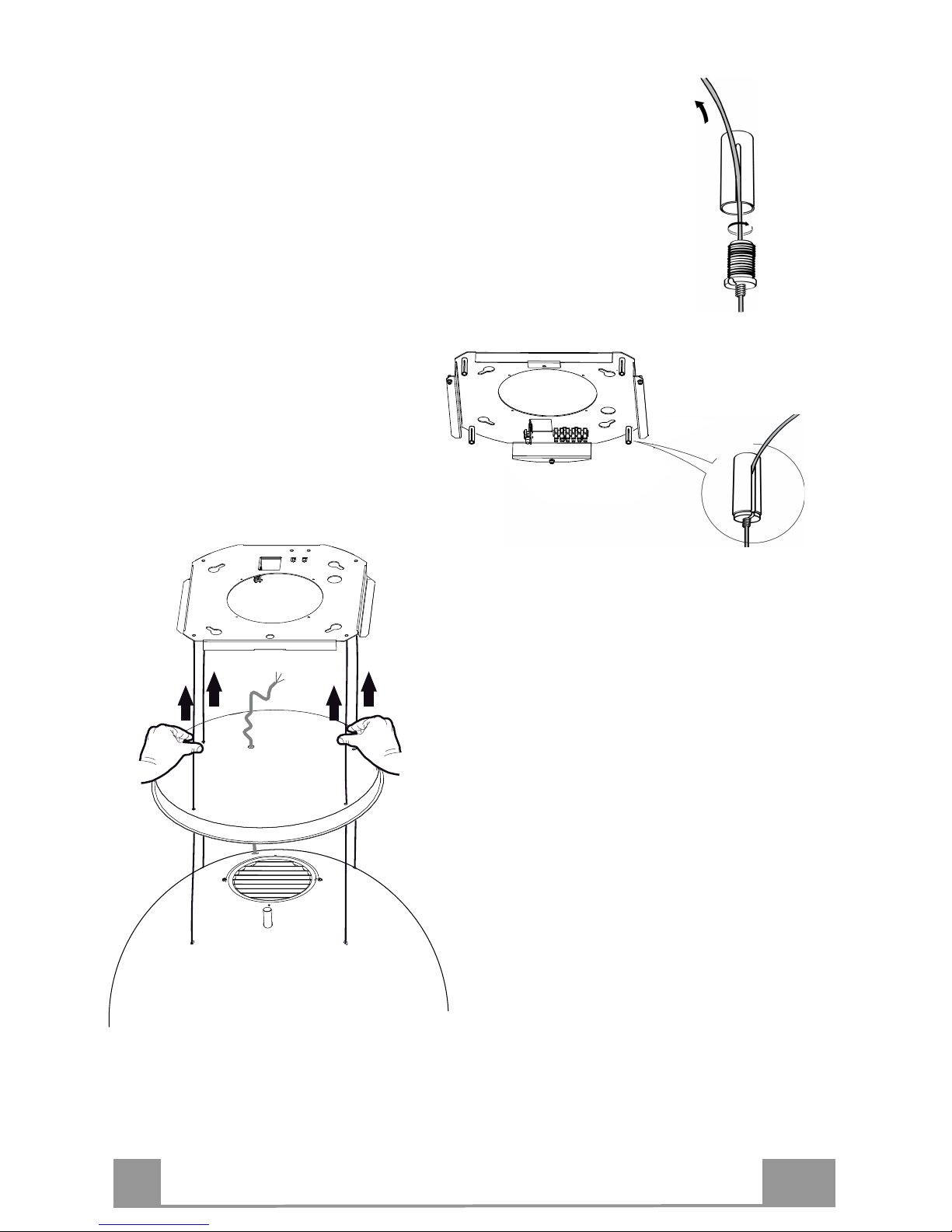
ES
6
61
• Pasar los cables por los ojales de los pasadores
roscados (a) y atornillar los tornillos
bloqueacables (b) en los mismos pasadores.
• Una vez terminada la operación el
resultado debe ser como se indica
en la figura para los 4 cables.
• Una vez llegados a este punto tenemos
l
os 4 cables conectados a la placa.
Poner en tensión los cables
empujándolos hacia lo alto de manera
que se desplacen dentro del tornillo
bloqueacable y fuera del ojal del
pasador roscado.
Esto es posible porque el tornillo
bloqueacable tiene un sistema que
permite el desplazamiento del cable en
su interior en un solo sentido
bloqueando el desplazamiento en el
sentido contrario.
Poner atención a que los cables tengan
todos la misma longitud para facilitar la
operación de nivelación final, y el cable
delantero izquierdo no debe estar más
aflojado que los demás.
Page 62

ES
6
62
FIJACIÓN DEL CABLE DE ALIMENTACIÓN
• Poner en tensión el cable de alimentación y fijarlo
a la brida en la placa del techo usando la lengüeta
ya montada con 2 tornillos.
• Insertar el pasacable de goma, ya introducido en el
cable de alimentación, en el ojal para evitar daños
futuros.
• Conectar la campana a la alimentación de red
interponiendo un interruptor bipolar con una
apertura de los contactos de por lo menos 3 mm.
• Quitar los Filtros antigrasa (ver párr.
"Mantenimiento") y comprobar que el conector
del cable de alimentación esté correctamente
insertado en la toma del aspirador.
• Ahora podemos cortar la abrazadera que bloquea
el cable de alimentación al cuerpo de la campana.
MONTAJE DE LA CUBIERTA DE LA PLACA
•
Atornillar nuevamente la cubierta a la placa con
los tornillos quitados antes.
SALIDA AIRE VERSIÓN FILTRANTE
Abrir el grupo iluminación tirándolo en la muesca específica.
Quitar el filtro antigrasa.
Comprobar la presencia de los filtros antiolor al carbono activo.
Page 63

ES
6
63
USO
Tablero de mandos
L T1
Tecla Función
Display
L
Enciende/Apaga las luces.
-
T1
Campana baja
Presionada por 2 segundos eleva la campana.
Presionado brevemente On/Off motor.
Encendido/Apagado
Campana baja
Primera presión: la campana baja.
Segunda presión: Stop campana
Una vez terminado el movimiento el motor se
enciende a la segunda velocidad.
Apagado/Apagado
La electrónica reconoce dos tipos de anomalías y procede a dar la relativa señalización
Led T1
Parpadeo lento
Superación del umbral de absorción corriente:
En el caso se verifique una condición de sobrecarga, se señala la anomalía
mediante el parpadeo cada 2 segundos del led T1 en el teclado. Verificar
que no hayan impedimentos durante el movimiento de la campana.
Esta señalización permanece activa hasta un nuevo mando de apertura/cierre
de la campana.
Parpadeo veloz
Intervención del micro de seguridad en la fase de
apertura:
En el caso de intervención del micro de seguridad, la anomalía es señalizada
por el led T1 que parpadea rápidamente (cada 250ms) lo cual significa que
la campana ha superado el fin de carrera…… Ponerse en contacto con la
Asistencia Técnica!
Durante esta anomalía siempre es posible acceder a las funciones de la
campana (luz y motor) y en el caso de motor encendido el led T1 seguirá
parpadeando señalando que la anomalía aún está presente.
Page 64

ES
6
64
MANDO REMOTO
Esta unidad puede ser controlada por medio de un mando remoto,
alimentado por una batería de 3 V tipo CR2032 (no incluida).
• No coloque el mando remoto cerca de fuentes de calor.
• No abandone las baterías en el medio ambiente, deposítelas en
los contenedores previstos.
Tablero de mandos
Enciende/Apaga el motor.
-
Campana cerrada
- Presionando la tecla brevemente la campana comienza a bajar.
- A la sucesiva presión se detiene.
Una vez term
i
nado el movimiento el motor se enciende a la 2°v.
-
Campana abierta:
- Si se mantiene presionada por 2 segundos activa el movimiento para la subida
que se detiene con el microinterruptor de tope.
- Presionando (brevemente) se detiene el movimiento (antes del tope).
- Presionando de nuevo brevemente on/off motor.
- Manteniéndola presionada por 2 segundos activa el movimiento para la
subida.
- Si el motor está encendido, antes detiene el motor y luego pone en marcha el
movimie
n
to.
-
-
-
Enciende/Apaga las luces de la campana.
-
INTENSIVA
- Activable sólo con la campana abajo y cuando no están activos el delay o el
24h.
- Activa la velocidad intensiva desde cualquier velocidad.
Para desconectarla basta presionar de nuevo la misma tecla o apagar el motor.
- La velocidad intensiva está temporizada en 6 minutos. Al terminar los 6
minutos el sistema se vuelve automáticamente a la velocidad implementada
precedentemente.
El led presente en la tecla
motor (de los
mandos campana) parpadea una vez
por segundo.
Presionada brevemente función Delay
Activable sólo cuando no está activa la Intensiva o la 24h.
Activa y desactiva la modalidad de parada total de la campana (motor + luces)
después de 30 minutos.
Para deshabilitar el Delay se puede presionar nuevamente la misma tecla o bien
apagar el motor.
El led prese
n-
te en la tecla
motor (de los
mandos campana) parpadea cada 0.5
segundos.
Manteniéndola presionada por 2 seg. Función 24H
Activable sólo cuando no está activa la Intensiva o el Delay.
Activa y desactiva la función 24 por 10 minutos cada hora, por 24 horas. Al
vencimiento se desactiva.
El led prese
n-
te en la tecla
motor (de los
mandos campana) parpadea cada 2
segundos.
Incrementa la velocidad del motor.
-
Decrementa la velocidad del motor.
-
Page 65

ES
6
65
LIMPIEZA Y MANTENIMIENTO
Filtro antigrasa metálico
Se puede lavar en lavavajillas, y necesita ser lavado almenos cada
2 meses de uso aproximadamente o más frecuentemente, para un
uso particularmente intenso.
LIMPIEZA FILTRO ANTIGRASA METÁLICO
• Abrir el grupo iluminación tirándolo en la muesca específica.
• Quitar el filtro, empujándolo hacia la parte posterior del grupo
y tirando simultáneamente hacia abajo.
• Lavar el filtro evitando doblarlo, y dejarlo secar antes de volverlo a montar.
• Montarlo nuevamente teniendo cuidado de mantener la manija
hacia la parte visible externa.
• Cerrar nuevamente el grupo iluminación.
Filtros antiolor al carbono activo (versión filtrante)
No se puede lavar y no es regenerable, debe sustituirse cada 4
meses de uso o más frecuentemente, para un uso particularmente
intenso.
SUSTITUCIÓN
• Abrir el grupo iluminación.
• Quitar el filtro antigrasa.
• Quitar los filtros antiolor al carbono activo saturados, como se
indica en (A).
• Montar los nuevos filtros, como se indica en (B).
• Montar nuevamente el filtro antigrasa y grupo iluminación.
A
B
Iluminación
• Para la sustitución ponerse en contacto con la Asistencia
Técnica ("Para la compra dirigirse a la asistencia técnica").
Page 66

ES
6
66
Indicaciones suplementarias para el instalador
Iluminación del cuerpo de la campana
Es posible regular el color y la intensidad de la iluminación del cuerpo de la campana
• Abrir el grupo iluminación tirándolo en la muesca específica.
• Regular la iluminación utilizando los botones del teclado B, siguiendo las indicaciones de la
etiqueta C
Procedimiento de intervención en caso de anomalías en el
movimiento
1. Verificar que el fusible esté correctamente insertado y no esté quemado, para
una eventual sustitución abrir el grupo iluminación y destornillar el portafusible
sustituyéndolo con uno de iguales características (Ref. A).
2. Verificar que el cuerpo campana esté instalado a nivel .
3. Verificar que los cuatro cables estén tendidos los cuatro de la misma manera.
Si las acciones precedentes no han resuelto el problema ponerse en contacto con la
Asistencia Técnica.
A
B
C
Page 67

ES
6
67
Regulación de la iluminación del cuerpo de la campana
Tecla
Color
Función
1 Rojo
Gestiona la intensidad del color rojo.
Manteniendo pulsada la tecla, la intensidad aumenta o disminuye cada vez que
se presiona.
La máxima y mínima intensidad se indican con un breve destello del color
seleccionado en la lámpara.
2 Negro
Gestiona la velocidad de los cambios de color cuando se utilizan ambos
programas de la tecla 4. Cada vez que se presiona la velocidad aumenta o
disminuye. La disminución se indica mediante un breve destello.
Se desactivan presionando la tecla 6.
3 Verde
Gestiona la intensidad del color verde.
Manteniendo pulsada la tecla, la intensidad aumenta o disminuye cada vez que
se presiona.
La máxima y mínima intensidad se indican con un breve destello del color
seleccionado en la lámpara.
4 Negro
Gestiona los 2 programas para el cambio de colores: matizado o intermitente.
Se desactivan presionando la tecla 6.
5 Azul
Gestiona la intensidad del color azul.
Manteniendo pulsada la tecla, la intensidad aumenta o disminuye cada vez que
se presiona.
La máxima y mínima intensidad se indican con un breve destello del color
seleccionado en la lámpara.
6 Negro
On –
Off Luz
Inicialmente en On el color de la campana es blanco. Se puede cambiar a
voluntad aumentando o disminuyendo la intensidad de los colores con las teclas
(1-3-5). Para volver a la situación inicial maximizar la intensidad la intensidad
de los 3 colores usando las teclas (1-3-5).
Pulsando durante 3 segundos la tecla se puede guardar la configuración de color
actual.
1
2
3
4
5
6
Page 68

GR
6
68
ΣΥΜΒΟΥΛΕΣ ΚΑΙ ΣΥΣΤΑΣΕΙΣ
Για τη δική σας ασφάλεια και για τη σωστή λειτουργία της συσκευής,
παρακαλούµε να διαβάσετε µε προσοχή τις παρούσες οδηγίες πριν την
εγκατάσταση και τη θέση σε λειτουργία. Φυλάσσετε αυτές τις οδηγίες
πάντα µαζί µε τη συσκευή, ακόµα και σε περίπτωση µεταβίβασης σε
τρίτους. Είναι σηµαντικό οι χρήστες να γνωρίζουν όλα τα χαρακτηριστικά
λειτουργίας και ασφάλειας της συσκευής.
Η σύνδεση των καλωδίων πρέπει να γίνει από έναν αρµόδιο τεχνικό.
•
Ο κατασκευαστής δεν µπορεί να θεωρηθεί υπεύθυνος για ενδεχόµενες
ζηµιές που οφείλονται σε ακατάλληλη εγκατάσταση ή χρήση.
•
Η ελάχιστη απόσταση ασφαλείας µεταξύ της επιφάνειας
των εστιών και του
απορροφητήρα είναι 650 mm (Ορισµένα µοντέλα µπορούν να
εγκατασταθούν σε µικρότερο ύψος. Ανατρέξτε στην παράγραφο µε τις
διαστάσεις λειτουργίας και εγκατάστασης).
•
Αν οι οδηγίες εγκατάστασης της µονάδας εστιών µε υγραέριο
υποδεικνύουν ότι απαιτείται απόσταση µεγαλύτερη από εκείνη που
αναφέρεται παραπάνω, είναι απαραίτητο να τις λάβετε υπόψη.
•
Βεβαιωθείτε ότι η τάση του δικτύου αντιστοιχεί στην τιµή που αναγράφεται
στην πινακίδα χαρακτηριστικών στο εσωτερικό του απορροφητήρα.
•
Τα συστήµατα διακοπής πρέπει να εγκατασταθούν στη µόνιµη
εγκατάσταση σύµφωνα µε τη νοµοθεσία για τις εγκαταστάσεις
καλωδίωσης.
•
Για τις συσκευές Κλάσης Ι, βεβαιωθείτε ότι το οικιακό δίκτυο τροφοδοσίας
είναι κατάλληλα γειωµένο.
•
Συνδέστε τον απορροφητήρα στην καπνοδόχο µε ένα σωλήνα µε ελάχιστη
διάµετρο 120 mm. Η διαδροµή των ατµών πρέπει να είναι όσο το δυνατόν
συντοµότερη.
•
Πρέπει να τηρούνται όλοι οι κανονισµοί αναφορικά µε
την εκκένωση του
αέρα.
•
Μη συνδέετε τον απορροφητήρα σε αγωγούς απαγωγής καπ
ναερίων που
παράγονται από καύση (π.χ. λέβητες, τζάκια κλπ.).
Page 69

GR
6
69
•
Αν χρησιµοποιείτε τον απορροφητήρα σε συνδυασµό µε άλλες µη ηλεκτρικές
συσκευές (π.χ. συσκευές υγραερίου), θα πρέπει να εξασφαλίσετε τον επαρκή
αερισµό του χώρου ώστε να εµποδίσετε την επιστροφή των καπναερίων. Όταν ο
απορροφητήρας της κουζίνας χρησιµοποιείται σε συνδυασµό µε µη ηλεκτρικές
συσκευές, η αρνητική πίεση του χώρου δεν πρέπει να υπερβαίνει τα 0,04 mbar έτσι
ώστε να αποφεύγεται η επιστροφή των καπναερίων στο χώρο και η αναρρόφησή
τους από τον απορροφητήρα.
•
Ο αέρας δεν πρέπει να απάγεται µέσω ενός αγωγού που χρησιµοποιείται για την
απαγωγή των καπναερίων από συσκευές καύσης που τροφοδοτούνται µε αέριο ή
άλλα καύσιµα.
•
Το ηλεκτρικό καλώδιο, αν πάθει ζηµιά, πρέπει να αντικατασταθεί από τον
κατασκευαστή ή από έναν τεχνικό του σέρβις.
•
Συνδέετε το φις σε µια πρίζα που συµµορφούται µε τους ισχύοντες κανονισµούς και
σε σηµείο µε εύκολη πρόσβαση.
•
Όσον αφορά τα τεχνικά µέτρα και τα µέτρα ασφαλείας π
ου πρέπει να εφαρµοστούν
για την απαγωγή των καπναερίων, είναι σηµαντικό να τηρούνται σχολαστικά οι
κανονισµοί των τοπικών φορέων.
ΠΡΟΕΙ∆ΟΠΟΙΗΣΗ: πριν εγκαταστήσετε τον απορροφητήρα, αφαιρέστε τις
προστατευτικές µεµβράνες.
•
Χρησιµοποιείτε µόνο βίδες και εξαρτήµατα κατάλληλου τύπου για τον
απορροφητήρα.
ΠΡΟΕΙ∆ΟΠΟΙΗΣΗ: η µη τοποθέτηση των βιδών και των συστηµάτων στερέωσης
σύµφωνα µε τις παρούσες οδηγίες, µπορεί να προκαλέσει ηλεκτροπληξία.
•
Μην κοιτάζετε απευθείας µε οπτικά όργανα (κιάλια, µεγεθυντικός φακός...).
•
Μην µαγειρεύετε φαγητά φλαµπέ κάτω από τον απορροφητήρα: µπορεί να
προκληθεί πυρκαγιά.
•
Αυτή η συσκευή µπορεί να χρησιµοποιηθεί από παιδιά ηλικίας άνω των 8 ετών και
από άτοµα µε µειωµένες ψυχικές ή διανοητικές ικανότητες, ή από άτοµα χωρίς πείρα
και επαρκή γνώση, αρκεί να επιβλέπονται και εκπαιδεύονται στην ασφαλή χρήση
της συσκευής και στους κινδύνους που απορρέουν από αυτή. Βεβαιωθείτε ότι τα
παιδιά δεν παίζουν µε τη συσκευή. Ο καθαρισµός και η συντήρηση δεν πρέπει να
εκτελούνται από παιδιά, εκτός εάν επιβλέπονται.
•
Τα παιδιά πρέπει να επιβλέπονται ώστε να εξασφαλιστε
ί ότι δεν παίζουν µε τη
συσκευή.
Page 70

GR
7
70
•
Η συσκευή δεν πρέπει να χρησιµοποιείται από άτοµα
(συµπεριλαµβανοµένων των παιδιών) µε µειωµένες ψυχικές ή
διανοητικές ικανότητες, ή από άτοµα χωρίς πείρα και επαρκή γνώση,
εκτός εάν ελέγχονται και εκπαιδεύονται.
Τα προσβάσιµα µέρη µπορεί να έχουν υψηλή θερµοκρασία κατά τη
χρήση των συσκευών µαγειρέµατος.
•
Καθαρίζετε ή/και αντικαθιστάτε τα φίλτρα µετά την καθορισµένη
χρονική περίοδο (κίνδυνος πυρκαγιάς). Βλέπε παράγραφο
Συντήρηση και καθαρισµός.
•
Πρέπει να υπάρχει κατάλληλος αερισµός στο χώρο όταν ο
απορροφητήρας χρησιµοποιείται ταυτόχρονα µε συσκευές που
χρησιµοποιούν αέριο ή άλλα καύσιµα (δεν ισχύει για συσκευές που
απάγουν αποκλειστικά τον αέρα στο χώρο).
•
Το σύµβολο
πάνω στο προϊόν ή πάνω στη συσκευασία του
υποδεικνύει ότι το προϊόν δεν πρέπει να διατίθεται σαν ένα
συνηθισµένο οικιακό απόρριµµα. Το προϊόν προς διάθεση πρέπει να
παραδίδεται σε ένα κατάλληλο κέντρο συλλογής για την ανακύκλωση
των ηλεκτρικών και ηλεκτρονικών συσκευών. Φροντίζοντας για τη
σωστή διάθεση αυτού του προϊόντος, συµβάλλετε στην αποφυγή
πιθανών αρνητικών επιπτώσεων για το περιβάλλον και την υγεία, που
µπορεί να οφείλονται στην ακατάλληλη διάθεσή του. Για
λεπτοµερέστερες πληροφορίες σχετικά µε την ανακύκλωση αυτού του
προϊόντος, απευθυνθείτε στο ∆ήµο, στην τοπική υπηρεσία συλλογής
απορριµµάτων ή στο κατάστηµα από το οποίο αγοράσατε το προϊόν.
Page 71

GR
7
71
ΧΑΡΑΚΤΗΡΙΣΤΙΚΑ
∆ιαστάσεις
Εξαρτήµατα
Αναφ. Ποσ. Εξαρτήµατα της συσκευής
1 1 Σώµα απορροφητήρα µε: Χειριστήρια, Φωτισµό,
Φίλτρα, Μοτέρ.
2 1 Πλάκα στήριξης απορροφητήρα.
Αναφ. Ποσ. Εξαρτήµατα για την εγκατάσταση
11 4 Ούπα Φ 10
12h 4 Βίδες 4,2 x 44,4
Ποσ. Έντυπα
1 Εγχειρίδιο οδηγιών
2
Page 72

GR
7
72
ΕΓΚΑΤΑΣΤΑΣΗ
Αυτός ο απορροφητήρας µπορεί να τοποθετηθεί σε οροφή/ράφι, πάνω (ελάχ. 650 mm) από µια
επιφάνεια εστιών µε νησίδα σε:
• Μοντέλο Ανακύκλωσης: Εσωτερική ανακύκλωση.
Σειρά ενεργειών για την εγκατάσταση
• Προετοιµασία για την εγκατάσταση
• ∆ιάτρηση οροφής/ραφιού και στερέωση πλάκας στήριξης
• Συνδέσεις
• Τοποθέτηση σώµατος απορροφητήρα
• Έλεγχος λειτουργίας
• ∆ιάθεση συσκευασίας
Άνοιγµα πλάκας και προετοιµασία για την τοποθέτηση
• Ξεβιδώστε τις βίδες που ενώνουν την πλάκα στο καπάκι της.
• Πάρτε την πλάκα και τοποθετήστε την µε τη σωστή κατεύθυνση, όπως δείχνει η εικόνα.
Page 73

GR
7
73
∆ιάτρηση οροφής/ραφιού και στερέωση πλάκας
∆ΙΑΤΡΗΣΗ ΟΡΟΦΗΣ/ΡΑΦΙΟΥ
• Με τη βοήθεια ενός νήµατος στάθµης σηµειώστε πάνω στην οροφή/ράφι στήριξης το
κέντρο της επιφάνειας των εστιών.
• Ακουµπήστε στην οροφή/ράφι την πλάκα προσέχοντας να την τοποθετήσετε µε τη σωστή
κατεύθυνση, όπως δείχνει η εικόνα.
• Σηµειώστε τα κέντρα των οπών της πλάκας.
• Τρυπήστε τα ακόλουθα σηµεία:
• Οροφή από συµπαγές σκυρόδεµα: ανάλογα µε τα ούπα για σκυρόδεµα που
χρησιµοποιούνται.
• Οροφή από τούβλα µε αεροθάλαµο, πάχους 20 mm: Ανοίξτε οπές Φ 10 mm (τοποθετήστε
αµέσως τα ούπα του εξοπλισµού 11).
• Οροφή από ξύλινα δοκάρια: ανάλογα µε τις ξυλόβιδες που χρησιµοποιούνται (δεν
διατίθενται).
• Ξύλινο ράφι, πάχους 15 mm: τρυπήστε µε ένα τρυπάνι Φ 7 mm.
• ∆ιέλευση του ηλεκτρικού καλωδίου τροφοδοσίας: τρυπήστε µε ένα τρυπάνι Φ 10 mm.
• Βιδώστε σταυρωτά δύο βίδες αφήνοντας 4-5 mm από την οροφή:
• για συµπαγές σκυρόδεµα, ούπα για σκυρόδεµα, δεν παρέχονται.
• για κατασκευή από τούβλα µε αεροθάλαµο, πάχους 20 mm περίπου, βίδες 12h, που
παρέχονται.
• για ξύλινα δοκάρια, ξυλόβιδες, δεν παρέχονται.
• για ξύλινο ράφι, βίδες µε ροδέλες και παξιµάδια δεν παρέχονται.
Page 74

GR
7
74
ΣΤΕΡΕΩΣΗ ΠΛΑΚΑΣ
• Σηκώστε την πλάκα στερέωσης και προσαρµόστε τα
ανοίγµατα στις δύο βίδες που τοποθετήσατε
προηγουµένως στην οροφή και γυρίστε έως το
κέντρο του ανοίγµατος ρύθµισης.
Προσοχή: Η φορά της πλάκας πρέπει να είναι εκείνη
που δείχνει η εικόνα
• Σφίξτε τις δύο βίδες και βιδώστε τις άλλες δύο βίδες
του εξοπλισµού. Πριν σφίξετε οριστικά τις βίδες,
µπορείτε να κάνετε ρυθµίσεις γυρνώντας το
εξάρτηµα, έτσι ώστε οι βίδες να µην εξέλθουν από
την έδρα του ανοίγµατος ρύθµισης.
• Η στερέωση πρέπει να είναι ασφαλής σε σχέση τόσο
µε το βάρος του απορροφητήρα όσο και στις
καταπονήσεις που οφείλονται στην ενδεχόµενη
πλευρική µετατόπιση της συσκευής. Μετά την
ολοκλήρωση της στερέωσης βεβαιωθείτε ότι η
πλάκα είναι σταθερή.
• Σε περίπτωση που η οροφή δεν είναι αρκετά
ανθεκτική στο σηµείο ανάρτησης, ο εγκαταστάτης θα
πρέπει να την ενισχύσει µε κατάλληλα αγκυρωµένα
ελάσµατα σε ανθεκτικά δοµικά σηµεία.
• Ελέγξτε το αλφάδιασµα της πλάκας στην οροφή.
Page 75

GR
7
75
ΣΥΝ∆ΕΣΗ ΚΑΛΩ∆ΙΩΝ ΑΠΟΡΡΟΦΗΤΗΡΑ-ΠΛΑΚΑΣ
ΠΡΟΣΟΧΗ: Πριν συνεχίσετε µε την εγκατάσταση, πρέπει να µετακινήσετε τον
απορροφητήρα σε ύψος τουλάχιστον 650 mm από την επιφάνεια των εστιών µε ένα
υποστήριγµα ή µε τη βοήθεια δεύτερου ατόµου. Προσέξτε να µην ξεπεράσετε τη µέγιστη
επέκταση του απορροφητήρα που υποδεικνύεται στο σχέδιο διαστάσεων.
Το µετρό αυτό είναι απαραίτητο, καθώς για να συνδεθούν τα συρµατόσχοινα του
απορροφητήρα στην πλάκα που είναι τοποθετηµένη στην οροφή είναι αναγκαίο το βάρος
του απορροφητήρα να µην πέφτει στο σκελετό.
Το σύστηµα στερέωσης των 4 συρµατόσχοινων περιλαµβάνει
3 µέρη:
• Βιδωτός πείρος (a) τοποθετηµένος στην πλάκα οροφής.
• Βίδα ασφάλισης συρµατόσχοινου (b) του εξοπλισµού.
• Πόµολο ασφαλείας (c) του εξοπλισµού.
• Π
εράστε τα 4 συρµατόσχοινα (που
είναι στερεωµένα στο σώµα
απορροφητήρα) στις αντίστοιχες οπές
του καλύµµατος πλάκας, που
αφαιρέσατε προηγουµένως,
προσέχοντας ώστε η κατεύθυνση να
είναι ίδια µε εκείνη της πλάκας που
είναι στερεωµένη στην οροφή.
• Βάλτε το ηλεκτρικό καλώδιο του
απορροφητήρα στην οπή που υπάρχει στο
καπάκι.
Προσοχή: Μην κόψετε ή αφαιρέσετε το
δεµατικό που στερεώνει το ηλεκτρικό
καλώδιο στον απορροφητήρα
b
c
a
Page 76

GR
7
76
• Προσέξτε τη φορά της πλάκας που στερεώνεται
στην οροφή (ο πείρος τερµατισµού της πλάκας
έχει άνοιγµα που προσαρµόζει στο καπάκι
πλάκας και στο σώµα του απορροφητήρα).
• Π
εράστε τα πόµολα ασφαλείας (c) στα
αντίστοιχα συρµατόσχοινα µε το
σπείρωµα προς τα πάνω.
• Περάστε τις βίδες ασφάλισης
συρµατόσχοινου (b) στα αντίστοιχα
συρµατόσχοινα.
B
C
Page 77

GR
7
77
• Περάστε τα συρµατόσχοινα στα ανοίγµατα
των βιδωτών πείρων (a) και βιδώστε τις βίδες
ασφάλισης συρµατόσχοινων (b) στους
πείρους.
• Όταν τελειώσετε, το αποτέλεσµα
πρέπει να είναι όπως της εικόνας
και µε τα 4 συρµατόσχοινα.
• Σ
το σηµείο αυτό και τα 4
συρµατόσχοινα είναι συνδεδεµένα
στην πλάκα.
Τεντώστε τα συρµατόσχοινα πιέζοντας
προς τα πάνω έτσι ώστε να κινηθούν
µέσα στη βίδα ασφάλισης
συρµατόσχοινου και έξω από το άνοιγµα
του βιδωτού πείρου.
Αυτό επιτρέπεται γιατί η βίδα
ασφάλισης συρµατόσχοινου διαθέτει ένα
σύστηµα που επιτρέπει την κίνηση του
συρµατόσχοινου στο εσωτερικό της
προς µία µόνο κατεύθυνση,
µπλοκάροντας την κίνηση προς την
αντίθετη φορά.
Προσέξτε ώστε τα συρµατόσχοινα να
έχουν το ίδιο µήκος για να
διευκολύνεται η διαδικασία του τελικού
αλφαδιάσµατος και το εµπρός αριστερό
συρµατόσχοινο δεν πρέπει να είναι πιο
λασκαρισµένο από τα άλλα.
Page 78

GR
7
78
ΣΤΕΡΕΩΣΗ ΗΛΕΚΤΡΙΚΟΥ ΚΑΛΩ∆ΙΟΥ
• Τεντώστε το ηλεκτρικό καλώδιο και στερεώστε το
στο στήριγµα πάνω στην πλάκα οροφής
χρησιµοποιώντας την ήδη τοποθετηµένη
προεξοχή µε 2 βίδες.
• Προσαρµόστε το λαστιχένιο στυπειοθλίπτη,
που είναι ήδη περασµένος στο ηλεκτρικό
καλώδιο, στο άνοιγµα για να αποφύγετε
µελλοντικές ζηµιές.
• Συνδέστε τον απορροφητήρα στο
δίκτυο παρεµβάλλοντας διπολικό
διακόπτη µε άνοιγµα επαφών
τουλάχιστον 3 mm.
• Βγάλτε τα φίλτρα για λίπη (βλ. παρ.
"Συντήρηση") και βεβαιωθείτε ότι ο
συνδετήρας του ηλεκτρικού καλωδίου
έχει συνδεθεί σωστά στην υποδοχή
της µονάδα αναρρόφησης.
• Στο σηµείο αυτό µπορείτε να κόψετε
το δεµατικό που στερεώνει το
ηλεκτρικό καλώδιο στο σώµα
απορροφητήρα.
ΤΟΠΟΘΕΤΗΣΗ ΚΑΠΑΚΙΟΥ ΠΛΑΚΑΣ
• Β
ιδώστε και πάλι το καπάκι στην πλάκα µε τις
βίδες που αφαιρέσατε προηγουµένως.
ΕΞΟ∆ΟΣ ΑΕΡΑ ΜΟΝΤΕΛΟΥ ΑΝΑΚΥΚΛΩΣΗΣ
• Α
νοίξτε το φωτιστικό τραβώντας το στην ειδική εγκοπή.
• Αφαιρέστε το φίλτρο λίπους.
• Βεβαιωθείτε για την παρουσία των φίλτρων ενεργού άνθρακα.
Page 79

GR
7
79
ΧΡΗΣΗ
Πίνακας χειριστηρίων
L T1
Πλή-
κτρο
Λειτουργία
Οθόν
η L
Ανάβει/Σβήνει τα φώτα.
-
T1
Απορροφητήρας κάτω
Αν το πιέσετε για 2 δευτερόλεπτα ανεβάζει στον απορροφητήρα.
Αν το πιέσετε για λίγο Ανάβει/Σβήνει το µοτέρ.
Αναµµένη/Σβηστή
Απορροφητήρας πάνω
Πρώτη πίεση: Ο απορροφητήρας κατεβαίνει.
∆εύτερη πίεση: Ο απορροφητήρας σταµατά.
Όταν ολοκληρωθεί η µετακίνηση, το µοτέρ ανάβει στη δεύτερη
ταχύτητα.
Σβηστή/Σβηστή
Το ηλεκτρονικό σύστηµα αναγνωρίζει δύο τύπους βλαβών και φροντίζει να δώσει την
αντίστοιχη σήµανση
Led T1
Αργή αναλαµπή
Υπέρβαση του ορίου α
πορρόφησης ρεύµατος:
Σε περίπτωση που παρουσιαστεί υπερφότωση, η βλάβη επισηµαίνεται µε
την αναλαµπή ανά 2 δευτερόλεπτα του Led T1 στον πίνακα χειριστηρίων.
Βεβαιωθείτε ότι δεν υπάρχουν εµπόδια κατά την κίνηση του
απορροφητήρα.
Αυτή η σήµανση παραµένει ενεργοποιηµένη µέχρι την επόµενη εντολή
ανοίγµατος/κλεισίµατος του απορροφητήρα.
Γρήγορη αναλαµπή
Επέµβαση του µικροδιακόπτη ασφαλείας κατά το άνοιγµα:
Σε περίπτωση επέµβασης του µικροδιακόπτη ασφαλείας, η ανωµαλία
επισηµαίνεται από το Led T1 που αναβοσβήνει γρήγορα (κάθε 250ms)
υποδεικνύοντας ότι ο απορροφητήρας έχει ξεπεράσει το στοπ
τερµατισµού...... Απευθυνθείτε στο Σέρβις!
Κατά τη διάρκεια αυτής της βλάβης µπορείτε να χρησιµοποιήσετε
τον απορροφητήρα (φώτα και µοτέρ) και σε περίπτωση που το
µοτέρ είναι αναµµένο το Led T1 θα συνεχίσει να αναβοσβήνει
επισηµαίνοντας ότι η βλάβη υπάρχει ακόµα.
Page 80

GR
8
80
ΤΗΛΕΧΕΙΡΙΣΤΗΡΙΟ
Η συσκευή ελέγχεται και µε τηλεχειριστήριο που δέχεται µια
µπαταρία των 3 V τύπου CR2032 (δεν περιλαµβάνεται).
• Μη βάζετε το τηλεχειριστήριο κοντά σε πηγές θερµότητας.
• Μην πετάτε τις µπαταρίες στο περιβάλλον, αλλά µόνο στους
ειδικούς κάδους.
Πίνακας χειριστηρίων
Ανάβει/Σβήνει το µοτέρ.
-
Απορροφητήρας κλειστός:
- Πιέζοντας για λίγο το πλήκτρο ο απορροφητήρας αρχίζει και κατεβαίνει
- Στην επόµενη πίεση σταµατά.
Όταν ολοκληρωθεί η µετακίνηση, το µοτέρ ανάβει στη 2η ταχύτητα.
-
Απορροφητήρας ανοιχτός:
- Αν το πιέσετε για 2 δευτερόλεπτα ενεργοποιείται η µετακίνηση για την άνοδο και
σταµατά µε το τερµατικό διαδροµής.
- Πιέζοντας (για λίγο) σταµατά η µετακίνηση (πριν από το τερµατικό διαδροµής).
- Πιέζοντας ακόµα για λίγο, ανάβει/σβήνει το µοτέρ.
- Αν πατηθεί για 2 δευτερόλεπτα ενεργοποιεί τη µετακίνηση για την άνοδο.
- Αν το µοτέρ είναι αναµµένο, πρώτα σταµατά το µοτέρ και στη συνέχεια αρχίζει τη
µετακίνηση.
-
- -
Ανάβει/Σβήνει τα φώτα του απορροφητήρα.
-
ΕΝΤΟΝΗ
- Ενεργοποιείται µόνο µε τον απορροφητήρα κατεβασµένο και όταν δεν έχει
ενεργοποιεί το delay ή το 24h.
- Ενεργοποιεί την έντονη ταχύτητα από όλες τις ταχύτητες.
Για την απενεργοποίηση αρκεί να πιέσετε πάλι το πλήκτρο ή να σβήσετε το µοτέρ.
- Η έντονη ταχύτητα ενεργοποιείται µε χρονοδιακόπτη 10 λεπτών. Με την
πάροδο των 10 λεπτών το σύστηµα επανέρχεται αυτόµατα στην προηγούµενη
ταχύτητα.
Το Led που
υπάρχει στο
πλήκτρο µοτέρ
(στα χειριστήρια
απορροφητήρα),
αναβοσβήνει 1
φορά το
δευτερόλεπτο.
Αν το πιέσετε για λίγο λειτουργία Delay:
∆εν επιλέγεται µε ενεργοποιηµένη τη λειτουργία Έντονη ή 24h.
Ενεργοποιεί και απενεργοποιεί τη λειτουργία ολικού σβησίµατος του απορροφητήρα
(µοτέρ+φωτισµός) µετά από 30 λεπτά:
Για να απενεργοποιήσετε τη λειτουργία Delay πιέστε το ίδιο πλήκτρο ή σβήστε το
µοτέρ.
Το Led που
υπάρχει στο
πλήκτρο µοτέρ
(στα χειριστήρια
απορροφητήρα),
αναβοσβήνει κάθε
0,5 δευτερόλεπτο.
Αν το πιέσετε για 2 δευτ. λειτουργία 24H:
∆εν επιλέγεται µε ενεργοποιηµένη τη λειτουργία Έντονη ή Delay.
Ενεργοποιεί ή απενεργοποιεί τη λειτουργία 24 για 10 λεπτά κάθε ώρα, για 24 ώρες.
Στο τέλος απενεργοποιείται.
Το Led που
υπάρχει στο
πλήκτρο µοτέρ
(στα χειριστήρια
απορροφητήρα),
αναβοσβήνει κάθε
2 δευτερόλεπτα.
Αυξάνει την ταχύτητα του µοτέρ.
-
Μειώνει την ταχύτητα του µοτέρ.
-
Page 81

GR
8
81
ΚΑΘΑΡΙΣΜΟΣ ΚΑΙ ΣΥΝΤΗΡΗΣΗ
Μεταλλικό φίλτρο για λίπη
Μπορεί να πλυθεί στο πλυντήριο πιάτων και απαιτεί καθαρισµό
τουλάχιστον κάθε 2 µήνες χρήσης ή συχνότερα σε περίπτωση
ιδιαίτερα συχνής χρήσης.
ΚΑΘΑΡΙΣΜΟΣ ΜΕΤΑΛΛΙΚΟΥ ΦΙΛΤΡΟΥ ΓΙΑ ΛΙΠΗ
• Ανοίξτε το φωτιστικό τραβώντας το στην ειδική εγκοπή.
• Βγάλτε το φίλτρο πιέζοντας προς το πίσω µέρος της συσκευής
και τραβώντας ταυτόχρονα προς τα κάτω.
• Πλύνετε το φίλτρο χωρίς να το στραβώσετε και αφήστε το να
στεγνώσει πριν το τοποθετήσετε στη θέση του.
• Τοποθετήστε το έτσι ώστε η λαβή να παραµείνει προς το
εξωτερικό µέρος.
• Κλείστε το φωτιστικό.
Φίλτρα ενεργού άνθρακα για οσµές (Μοντέλο ανακύκλωσης)
∆εν µπορεί να πλυθεί και να αναγεννηθεί και πρέπει να
αντικαθίσταται περίπου κάθε 4 µήνες χρήσης ή συχνότερα σε
περίπτωση ιδιαίτερα συχνής χρήσης.
ΑΝΤΙΚΑΤΑΣΤΑΣΗ
• Ανοίξτε το φωτιστικό.
• Αφαιρέστε το φίλτρο λίπους.
• Βγάλτε τα κορεσµένα φίλτρα ενεργού άνθρακα όπως στο
σχέδιο (A).
• Τοποθετήστε τα νέα φίλτρα όπως στο σχέδιο (B).
• Τοποθετήστε το φίλτρο για λίπη και το φωτιστικό.
A
B
Φωτισµός
• Για την αντικατάσταση απευθυνθείτε στο Σέρβις ("Για την
αγορά απευθυνθείτε στο Σέρβις").
Page 82

GR
8
82
Συµπληρωµατικές οδηγίες για τον εγκαταστάτη
Φωτισµός σώµατος απορροφητήρα
Μπορείτε να ρυθµίσετε το χρώµα και την ένταση του φωτισµού του σώµατος απορροφητήρα
• Ανοίξτε το φωτιστικό τραβώντας το στην ειδική εγκοπή.
• Ρυθµίστε το φωτισµό, χρησιµοποιώντας τα πλήκτρα του πληκτρολόγιου B, ακολουθώντας
τις οδηγίες που αναγράφονται στην ετικέτα C
∆ιαδικασία επέµβασης σε περίπτωση ανωµαλίας στην κίνηση
1. Βεβαιωθείτε ότι η ασφάλεια είναι σωστά τοποθετηµένη και δεν έχει
καεί. Για ενδεχόµενη αντικατάσταση, ανοίξτε το φωτιστικό,
ξεβιδώστε την ασφάλεια και αντικαταστήστε την µε ασφάλεια ίδιων
χαρακτηριστικών (αναφ. A).
2. Βεβαιωθείτε ότι το σώµα του απορροφητήρα είναι αλφαδιασµένο.
3. Βεβαιωθείτε ότι και τα τέσσερα συρµατόσχοινα είναι τεντωµένα µε
τον ίδιο τρόπο.
Εάν οι προηγούµενες ενέργειες δεν λύσουν το πρόβληµα, απευθυνθείτε
στο Σέρβις.
A
B
C
Page 83

GR
8
83
Ρύθµιση του φωτισµού του σώµατος απορροφητήρα
Πλήκτρο
Χρώµα
Λειτουργία
1 Κόκκινο
Ελέγχει την ένταση του κόκκινου χρώµατος.
Κρατώντας το πλήκτρο πατηµένο η ένταση αυξάνεται ή µειώνεται σε κάθε
πίεση.
Τα µέγιστα και ελάχιστα όρια της έντασης επισηµαίνονται από µια
σύντοµη αναλαµπή του επ
ι
λεγµένου χρώµατος στο φωτιστικό.
2 Μαύρο
Ελέγχει την ταχύτητα αλλαγής των χρωµάτων όταν χρησιµοποιούνται και
τα δύο προγράµµατα του πλήκτρου 4. Σε κάθε πίεση η ταχύτητα αυξάνεται
ή µειώνεται. Η µείωση επισηµαίνεται από µια σύντοµη αναλαµπή.
Απενεργοποιούνται πιέζοντας το πλ
ή
κτρο 6.
3 Πράσινο
Ελέγχει την ένταση του πράσινου χρώµατος.
Κρατώντας το πλήκτρο πατηµένο η ένταση αυξάνεται ή µειώνεται σε κάθε
πίεση.
Τα µέγιστα και ελάχιστα όρια της έντασης επισηµαίνονται από µια
σύντοµη αναλαµπή του επ
ι
λεγµένου χρώµατος στο φωτιστικό.
4 Μαύρο
Ελέγχει τα 2 προγράµµατα για την αλλαγή των χρωµάτων: Απαλό ή που
αναβοσβήνει.
Απενεργοποιούνται πιέζοντας το πλ
ή
κτρο 6.
5 Μπλε
Ελέγχει την ένταση του µπλε χρώµατος.
Κρατώντας το πλήκτρο πατηµένο η ένταση αυξάνεται ή µειώνεται σε κάθε
πίεση.
Τα µέγιστα και ελάχιστα όρια της έντασης επισηµαίνονται από µια
σύντοµη αναλαµπή
του επ
ι
λεγµένου χρώµατος στο φωτιστικό.
6 Μαύρο
Ανάβει
– Σβήνει το φως
Αρχικά στο On το χρώµα του απορροφητήρα είναι λευκό. Μπορείτε να το
αλλάξετε κατά βούληση αυξάνοντας ή µειώνοντας την ένταση των
χρωµάτων µε τα πλήκτρα (1-3-5). Για να επιστρέψετε στην αρχική
κατάσταση αυξήστε στο µέγιστο την ένταση και των 3 χρωµάτων µε τα
πλήκτρα (1-3-5).
Πιέζοντας το πλήκτρο για 3 δευτερόλεπτα µπορείτε να αποθηκεύσετε το
επιλεγµένο χρώµα.
1
2
3
4
5
6
Page 84

RU
8
84
ИНФОРМАЦИЯ ПО БЕЗОПАСНОСТИ
В целях собственной безопасности и для правильной работы прибора
рекомендуется внимательно прочитать руководство, прежде чем
приступать к его установке и вводу в действие. Храните руководство
всегда вместе с прибором также в случае передачи его третьим
лицам. Знание пользователями всех параметров работы и
безопасности прибора имеет большое значение.
Подключение электрических проводов должно выполняться
компетентным специалистом.
•
Изготовитель не несет ответственность за убытки, возникающие в
результате неправильной установки или эксплуатации прибора.
•
Безопасное расстояние между варочной панелью и всасыва
ющей
вытяжкой должно быть не менее 650 мм (некоторые модели можно
устанавливать ниже; см. раздел, посвященный рабочим размерам и
операциям по установке прибора).
•
Если в инструкциях по установке газовой плиты сказано, что
расстояние до вытяжки должно быть больше указанного выше,
следует придерживаться предписанных размеров.
•
Проверьте соответствие напряжения сети указанному на табличке,
закрепленной внутри вытяжки.
•
В соответствии с нормативными правилами монтажа электропроводки
в стационарной электрической сети должны быть установлены
разъединители.
•
Для приборов класса I проверьте, чтобы в электрической сети вашего
дома была предусмотрена соответствующая система заземления.
•
Соедините вытяжку с дымоходом трубой, диаметр которой должен
быть не менее 120 мм. Труба для отведения дыма должна быть как
можно короче.
•
Соблюдайте все нормативные требования по отведению
отр
аботанного воздуха.
•
Не соединяйте всасывающую вытяжку с дымоходами, по кот
орым
выводится дым, образующийся в процессе горения (например,
отопительные котлы, камины и проч.).
Page 85

RU
8
85
•
Если вытяжной шкаф используется в сочетании с приборами, работающими
не от электрического тока (например, газовые приборы), помещение должно
хорошо проветриваться во избежание обратного потока отходящих газов.
При пользовании кухонной вытяжкой в сочетании с приборами,
работающими не от электрического тока, отрицательное давление в
помещении не должно превышать 0,04 мбар с тем, чтобы дым не
всасывался вытяжкой обратно в помещение.
•
Воздух не должен выводиться из помещения по каналу для отведения
продуктов горения, выделяемых приборами, работающими на газу или
других горючих веществах.
•
В случае повреждения кабеля питания он должен быть заменен
изготовителем или техническим специалистом сервисного центра.
•
Вставьте вилку в розетку, расположенную в доступном месте; тип розетки
должен соответствовать действующим нормативным правилам.
•
Необходимо строго соблюдать правила местных учреждений
,
устанавливающие технические требования и меры безопасности для систем
отведения дыма.
ПРЕДУПРЕЖДЕНИЕ: прежде чем приступить к установке кухонной
вытяжки, снимите с нее защитную пленку.
•
Используйте только винты и метизы, пригодные для установки вытяжного
шкафа.
ПРЕДУПРЕЖДЕНИЕ: использование винтов или зажимных устройств, не
соответствующих указаниям данных инструкций, может привести к
возникновению опасных ситуаций и к электрическим ударам.
•
Не рекомендуется прямо смотреть на лампочку через оптические приборы
(бинокль, увеличительное стекло и проч.).
•
Не готовьте блюда фламбе под вытяжкой: опасность возникновения пожара.
•
Прибором могут пользоваться дети старше 8 лет и лица с ограниченными
психическими, физическими и сенсорными способностями, а также не
имеющие достаточного опыта и знаний, но только под присмотром
ответственных лиц и при условии, что они обучены безопасной эксплуатации
прибора и знают о связанных с его неправильным использованием
опасностях. Следите, чтобы дети не играли с прибором. Очистку и уход за
прибором не должны выполнять дети, разве только под присмотром
взрослых.
•
Следите, чтобы детьми не играли с прибором.
Page 86

RU
8
86
•
Запрещается пользоваться прибором лицам (а также детям) с
ограниченными психическими, физическими и сенсорными
способностями, а также, не имеющим достаточного опыта и знаний;
в противном случае они должны быть соответствующим образом
обучены и находиться под наблюдением.
Доступные части прибора могут сильно нагреваться в процессе
приготовления пищи.
•
Очищайте и/или заменяйте фильтры по истечении указанного
периода времени (опасность возникновения пожара). См. раздел,
посвященный уходу и очистке прибора.
•
В помещении должна быть предусмотрена соответствующая
вентиляция, когда вытяжка используется одновременно с
приборами, работающими на газу или другом топливе (это правило
не распространяется на приборы, выпускающие воздух только в
помещение).
•
Символ
на изделии или на упаковке указывает, что прибор
нельзя выбрасывать, как обычный бытовой мусор. Прибор,
подлежащий уничтожению, необходимо сдать в специальный
сборный пункт для повторного использования электрических и
электронных компонентов. Пользователь, правильно сдающий
прибор на переработку, помогает предотвратить потенциальные
негативные последствия для окружающей среды и для здоровья
людей, возникающие в случае неправильного его уничтожения. За
более подробной информацией о вторичном использовании прибора
обращайтесь в городской совет, в местную службу по переработке
отходов или в магазин, где прибор был приобретен.
Page 87

RU
8
87
ХАРАКТЕРИСТИКИ
Габариты
Части
Об. Кол. Части изделия
1 1 Корпус вытяжки в комплекте с устройствами
управления, освещением, фильтрами, двигателем
2 1 Опорная плита вытяжки
Об. Кол. Установочные компоненты
11 4 Дюбели ø 10
12h 4 Винты 4,2 x 44,4
Кол. Документация
1 Руководство по эксплуатации
2
Page 88

RU
8
88
УСТАНОВКА
Вытяжка может быть закреплена к потолку/полке на расстоянии не менее 650 мм от
независимой варочной панели:
• Фильтрующая вытяжка: рециркуляция воздуха в помещении.
Последовательность операций по установке
• Подготовка к установке
• Отверстие в потолке/полке и крепление опорной плиты
• Соединения
• Установка корпуса вытяжки
• Функциональная проверка
• Уничтожение упаковочных материалов
Подготовка к установке монтажной плиты
• Отвинтите винты, соединяющие монтажную плиту с ее крышкой.
• Возьмите плиту и разместите ее, как показано на рисунке.
Page 89

RU
8
89
Отверстия в потолке/полке и крепление плиты
ПОДГОТОВКА ОТВЕРСТИЙ В ПОТОЛКЕ/ПОЛКЕ
• С помощью отвеса определите на потолке/подвесной полке центр варочной панели.
• Приложите к потолку/полке плиту, как показано на рисунке.
• Отметьте центры отверстий плиты.
• Просверлите отверстия.
• В потолке из компактного бетона: в соответствии с используемыми для бетона
дюбелями.
• В потолке из пустотелого кирпича толщиной 20 мм: отверстия ø 10 мм (сразу же
вставьте прилагаемые дюбели 11 ).
• В потолке из деревянных балочных перекрытий: в соответствии с используемыми
шурупами для дерева (не входят в комплект поставки).
• В деревянной полке толщиной 15 мм: отверстие ø 7 мм
• Проходное отверстие для электрического кабеля питания: отверстие ø 10 мм
• Ввинтите крест-накрест два винта, оставив до потолка 4-5 мм:
• в потолок из компактного бетона - дюбели для бетона (не входят в комплект
поставки)
• в потолок из пустотелого кирпича толщиной около 20 мм - прилагаемые винты 12h
• в потолок из деревянных балочных перекрытий - шурупы для дерева (не входят в
комплект поставки)
• в деревянную полку - шурупы с шайбами и гайками (не входят в комплект
поставки).
Page 90

RU
9
90
КРЕПЛЕНИЕ ПЛИТЫ
• Приподнимите установочную плиту и вставьте в
отверстия два винта, предварительно
подготовленные в потолке; поверните плиту до
центра регулировочного отверстия.
Внимание: направление установки плиты должно
соответствовать показанному на рисунке.
• Затяните оба винта и привинтите еще два винта,
прилагаемые в комплекте; прежде чем затянуть
винты окончательно, поворотом плиты можно
отрегулировать ее положение; следите, чтобы
винты при этом не вышли из регулировочного
отверстия.
• Крепление плиты должно быть надежным
относительно веса вытяжки и нагрузок,
оказываемых случайными боковыми толчками на
установленный прибор. После завершения
операций проверьте устойчивое положение
плиты.
• Во всех случаях, когда потолок недостаточно
прочен в точке крепления прибора, монтажник
должен упрочить его специальными пластинами
и опорными плитами, закрепленными к
устойчивым структурным элементам.
• Проверьте уровень крепления плиты к потолку.
Page 91

RU
9
91
СОЕДИНЕНИЕ ПРОВОДОВ
ВЫТЯЖКА
- ПЛИТА
Прим. прежде чем продолжить установку, поднимите вытяжку на высоту на менее
650 мм над варочной панелью, установив опору, или с помощью второго человека.
Следует проследить за тем, чтобы вытяжка не выступала далее, чем указано на
чертеже с габаритными размерами.
Это необходимо, так как во время соединения проводов вытяжки с закрепленной к
потолку плитой вес прибора не должен отягощать структуру.
Система крепления 4 проводов состоит из 3 частей
• Защелка с резьбой (a), установленная на потолочной плите.
• Кабельный фиксатор (b), прилагаемый в комплекте.
• Предохранительная рукоятка (c), прилагаемая в комплекте.
• Пропустите 4
провода (прикреплены
к корпусу вытяжки) в
соответствующие отверстия в
заранее снятой крышке плиты, следя
за тем, чтобы сторона крышки
соответствовала стороне плиты,
смонтированной на потолке.
• Вставьте кабель питания вытяжки в
отверстие, предусмотренное в крышке.
Внимание! Хомутик, обеспечивающий
крепление кабеля питания к вытяжке,
должен оставаться на своем месте и не
иметь никаких повреждений.
а
b
c
Page 92

RU
9
92
• Обратите внимание на положение,
в котором плита закреплена
к потолку (ограничительной
собачке соответствует отверстие
в крышке плиты и в корпусе вытяжки).
• Пос
тавьте предохранительные
рукоятки (c) на соответствующие
провода; при этом резьба должна
быть обращена вверх.
• Поставьте кабельные фиксаторы (b)
на соответствующие кабели.
B
C
Page 93

RU
9
93
• Пропустите провода через отверстия в защелках с
резьбой (a) и привинтите винты кабельных фиксаторов
(b) к защелкам.
• По завершении операции все 4
провода должны быть
закреплены, как показано на
рисунке.
• Таким об
разом все 4 провода
соединены с плитой.
Подайте на провода напряжение,
прижав их кверху, чтобы они
проходили внутри кабельных
фиксаторов и снаружи отверстия
защелки с резьбой.
В конструкции кабельных
фиксаторов предусмотрена система,
позволяющая кабелю скользить
внутри фиксаторов только в одном
направлении.
Следите, чтобы все провода были
одинаковой длины (это необходимо
для заключительного выравнивания
вытяжки), и чтобы левый передний
трос не был натянут меньше, чем
другие.
Page 94

RU
9
94
КРЕПЛЕНИЕ КАБЕЛЯ ПИТАНИЯ
• Натяните кабель питания и закрепить его 2
винтами на скобе на потолочной плите с
помощью уже установленного язычка.
• Разместите уже поставленный на кабель
питания резиновый уплотнитель в отверстии
во избежания его повреждения в будущем.
• Соедините вытяжку с сетью питания; для
этого установите двухполюсный
выключатель с минимальным разведением
контактов 3 мм.
• Выньте жировые фильтры (см. раздел
"Обслуживание") и проверьте, чтобы
соединительный зажим питающего кабеля
был правильно вставлен в разъем вытяжного
устройства.
• После этого можно срезать хомутик,
которым кабель питания крепится к корпусу
вытяжки.
УСТАНОВКА ВЕРХНЕЙ ПАНЕЛИ МОНТАЖНОЙ ПЛИТЫ
• Пр
икрутитe крышку к монтажной плите, с помощью
винтов, выкрученных ранее.
ВЫПУСК ВОЗДУХА ИЗ ФИЛЬТРУЮЩЕЙ ВЫТЯЖКИ
• Потяните за специальный вырез и откройте осветительный прибор.
• Удалить жировой фильтр.
• Проверьте наличие фильтров против запахов на активированном угле.
Page 95

RU
9
95
ЭКСПЛУАТАЦИЯ
Панель управления
L T1
Кнопка Функция Дисплей
L Включает и выключает освещение. -
T1 Вытяжка в нижнем положении
При нажатии в течение 2 секунд поднимает
вытяжку.
При кратком нажатии включает и выключает
двигатель.
Включено / выключено
Вытяжка в верхнем положении
Первое нажатие: Вытяжка опускается.
Второе нажатие: Вытяжка останавливается.
По завершении движения вытяжки двигатель
включается на второй скорости.
Выключено / выключено
Электроника распознает два типа неисправностей и подает соответствующие
сигналы
Индикатор T1
Медленное мигание
Превышение порога потребления тока
При выявлении условий перегрузки система сигнализирует о
неисправности миганием индикатора T1 на кнопочной панели каждые
2 секунды. Проверьте, чтобы движению вытяжки ничто не мешало.
Такой сигнал сохраняется до новой команды раскрытия/закрытия
вытяжки.
Быстрое мигание
Срабатывание защитного микровыключателя на этапе раскрытия
При срабатывании защитного микровыключателя о неисправности
сигнализирует быстро мигающий T1 индикатор (каждые 250 мсек),
указывающий на то, что вытяжка зашла за ограничительный
предел…….. Обратитесь в техническое обслуживание!
Во время этой неисправности можно все равно пользоваться
функциями вытяжки (освещение и двигатель), и если двигатель
включен, индикатор T1 будет продолжать мигать, указывая на то, что
неисправность еще присутствует.
Page 96

RU
9
96
ПУЛЬТ ДИСТАНЦИОННОГО УПР
АВЛЕНИЯ
Работой прибора можно управлять пультом дистанционного
управления, который работает на батарейке 3 В типа CR2032 (не
входит в комплект поставки).
• Не оставляйте пульт дистанционного управления около источников
тепла.
• Не выбрасывайте батарейки в мусор, а только в специальные
емкости по сбору отработанных батареек.
Панель управления
Включает / выключает двигатель.
-
Вытяжка закрыта
:
- кратким нажатием на кнопку вытяжка начинает опускаться
- при следующем нажатии на кнопку вытяжка останавливается.
По завершении движения вытяжки двигатель включается на 2
-
й скорости.
-
Вытяжка открыта
:
- нажатие кнопки в течение 2 секунд включает подъем вытяжки, которая
останавливается ограничи телем
- кратким нажатием кнопки движение вытяжки прекращается (до
ограничителя)
- еще одним кратким нажатием кнопки включается / выключается двигатель
- нажатие кнопки в течение 2 секунд включает подъем вытяжки
- если двигатель включен, сначала останавливает его, а потом включает
движение вытяжки
-
- -
Включает / выключает освещение вытяжки.
-
ИНТЕНСИВНАЯ СКОРОСТЬ
- Такая скорость может быть включена, только когда вытяжка в нижнем
положении и не включены функции задержка или 24h.
- Включает интенсивную скорость при любой скорости работы.
Чтобы отключить интенсивную скорость, достаточно еще раз нажать эту же
кнопку или выключить двигатель.
- Интенсивная скорость ограничена таймером на 6 минут. По истечении 6
минут система автоматически возвращается на заданную ранее скорость.
Индикатор на
кнопке управлен
ия
двигателем (в
числе устройств
управления
вытяжкой) мигает
1 раз в секунду.
Краткое нажатие кнопки активирует функцию задержки
:
Эта функция может быть включена, только когда не активированы функции
интенсивная скорость или 24h.
Включает и отключает режим полного останова вытяжки (двигатель и
освещение) через 30 минут.
Чтобы отключить функцию задержки, можно еще раз нажать эту же кнопку
или выключить двигатель.
Индикатор на
кнопке управления
двигателем (в
числе устройств
управления
вытяжкой) мигает
каждые 0,5
секунды.
При нажатии кнопки в течение 2 сек функция 24H
:
может быть включена, только когда не активированы функции интенсивная
скорость или задержка.
Кнопка включает и выключает функцию 24 ч с периодичностью 10 минут
каждый час в течение 24 часов. По истечение этого времени функция
отключается.
Индикатор на
кнопке управления
двигателем (в
числе устройств
управления
вытяжкой) мигает
каждые 2 секунды.
Повышает скорость работы двигателя.
-
Понижает скорость работы двигателя.
-
Page 97

RU
9
97
ОЧИСТКА И ОБСЛУЖИВАНИЕ
Металлический жировой фильтр
Фильтр можно мыть в посудомоечной машине. Его следует
мыть примерно раз в 2 месяца работы или чаще в случае
особенно интенсивного использования.
ОЧИСТКА МЕТАЛЛИЧЕСКОГО ЖИРОВОГО ФИЛЬТРА
• Потяните за специальную выемку, чтобы открыть блок
освещения.
• По очереди выньте фильтры. Для этого прижмите их к
задней стенке блока и одновременно потяните вниз.
• Осторожно вымойте фильтры, следя за тем, чтобы они не
сгибались, и перед установкой дайте им просохнуть.
• Поставьте фильтры на место так, чтобы ручка находилась
с видимой наружной стороны.
• Закройте блок освещения.
Фильтры против запахов на активированном угле
(фильтрующая вытяжка)
Такие фильтры нельзя мыть и восстанавливать. Их следует
менять приблизительно каждые 4 месяца работы или чаще в
случае особенно интенсивного использования.
ЗАМЕНА
• Откройте осветительный прибор.
• Удалить жировой фильтр.
• Выньте насыщенные фильтры против запахов на
активированном угле, как показано на рисунке (A).
• Установите новые фильтры, как показано на рисунке (B).
• Вставьте жировой фильтр и установите осветительный
прибор.
A
B
Освещение
• Для замены светодиода обращайтесь в обслуживающий
центр ("Для приобретения обращайтесь в обслуживающий
центр").
Page 98

RU
9
98
Дополнительные указания для монтажника
Освещение корпуса вытяжки
В данной модели предусмотрена возможность регулировки оттенка цвета и
интенсивности освещения корпуса вытяжки.
• Потяните за специальный вырез и откройте осветительный прибор.
• Отрегулируйте освещение, пользуясь кнопками на панели B и следуя при этом
указаниям, приведенным на наклейке C
Операции в случае неправильного движения
1. Проверьте, чтобы предохранитель не перегорел и был правильно
вставлен, при необходимости в его замене откройте осветительный
прибор, отвинтите плавкую вставку и замените предохранитель на
другой с такими же характеристиками (Об.A).
2. Убедитесь, что корпус вытяжки выставлен по уровню.
3. Убедитесь в одинаковом натяжении четырех тросов.
Если с помощью таких проверок проблема не решена, обратитесь в Центр
технического обслуживания.
A
B
C
Page 99

RU
9
99
Регулировка освещения корпуса вытяжки
Кноп
ка
Цвет
Функция
1 Красный
Регулирует яркость красного цвета.
При каждом длительном нажатии кнопки яркость цвета увеличивается или
уменьшается.
На максимальный и минимальный предел яркости указывает краткая
вспышка выбранного на светильнике цвета.
2 Черный
Регулирует скорость переключения цвета при использовании обеих
программ кнопки 4. При каждом нажатии скорость увеличивается или
уменьшается. На снижение скорости указывает краткая вспышка.
Функция отключается нажатием кнопки 6.
3 Зеленый
Регулирует яркость зеленого цвета.
При каждом длительном нажатии кнопки яркость цвета увеличивается или
уменьшается.
На максимальный и минимальный предел яркости указывает краткая
вспышка выбранного на светильнике цвета.
4 Черный
Регулирует работу 2 программ изменения цвета. Рассеянный или
мигающий.
Функция отключается нажатием кнопки 6.
5 Синий
Регулирует яркость синего цвета.
При каждом длительном нажатии кнопки яркость цвета увеличивается или
уменьшается.
На максимальный и минимальный предел яркости указывает краткая
вспышка выбранного на светильнике цвета.
6 Черный
Вкл
- Выкл. освещения
Сначала при включении освещение вытяжки белого цвета. Освещение
можно изменить по желанию, а также увеличить или уменьшить яркость
цвета кнопками (1-3-5). Чтобы вернуться к изначальной ситуации, следует
максимально увеличить яркость всех 3 цветов с помощью кнопок (1-3-5).
Нажатием кнопки в течение 3 секунд можно сохранить в памяти
устройства настроенный в настоящий момент цвет.
1
2
3
4
5
6
Page 100

NL
1
100
VEILIGHEIDSINFORMATIE
Lees voor uw eigen veiligheid en voor een correcte werking van het
apparaat eerst deze handleiding aandachtig door, alvorens het apparaat
te installeren en te gebruiken. Bewaar deze instructies altijd bij het
apparaat, ook wanneer u het verkoopt of overdraagt aan derden.
Gebruikers moeten volledig op de hoogte zijn van de werking en de
veiligheidsfuncties van het apparaat.
De kabels moeten door een ervaren monteur worden aangesloten.
•
De fabrikant is niet aansprakelijk voor eventuele schade als gevolg van
een onjuiste installatie of oneigenlijk gebruik.
•
De minimale veiligheidsafstand tussen de kookplaat e
n de afzuigkap is
650 mm (sommige modellen kunnen op een kleinere afstand worden
geïnstalleerd; zie de paragraaf over de werkafmetingen en de installatie).
•
Als de installatievoorschriften van de gaskookplaat bepalen dat een
grotere afstand in acht moet worden genomen dan hierboven is
aangegeven, dan moet daar rekening mee worden gehouden.
•
Controleer of de netspanning overeenstemt met de spanning die op het
typeplaatje aan de binnenkant van de afzuigkap staat vermeld.
•
Er moeten lastscheiders in de vaste installatie worden geïnstalleerd in
overeenstemming met de normen over bedradingssystemen.
•
Controleer voor apparaten van klasse I of het elektriciteitsnet in uw
woning over een goede aarding beschikt.
•
Sluit de afzuigkap op het rookkanaal aan met een pijp met een minimale
diameter van 120 mm. De rook moet een zo kort mogelijk traject
afleggen.
•
Alle regels voor de luchtafvoer moeten in acht worden genomen.
•
Sluit de afzuigkap niet op rookkanalen aan die verbrandingsgassen
afvoeren (bijv. van verwarmingsketels, open haarden, enz.).
 Loading...