

Page 1

XTR B
EN
Page 2

© Copyright FAAC S.p.A. dal 2017. Tutti i diritti
riservati.
Nessuna parte di questo manuale può essere riprodotta, archiviata, distribuita a terzi né altrimenti
copiata, in qualsiasi formato e con qualsiasi mezzo,
sia esso elettronico, meccanico o tramite fotocopia,
senza il preventivo consenso scritto di FAAC S.p.A.
Tutti i nomi e i marchi citati sono di proprietà dei
rispettivi fabbricanti.
I clienti possono effettuare copie per esclusivo
utilizzo proprio.
Questo manuale è stato pubblicato nel 2017.
© Copyright FAAC S.p.A. from 2017. All rights
reserved.
No part of this manual may be reproduced, archived,
distributed to third parties nor copied in any other
way, in any format and with any means, be it
electronic, mechanical or by photocopying, without
prior written authorisation by FAAC S.p.A.
All names and trademarks mentioned are the property of their respective manufacturers.
Customers may make copies exclusively for their
own use.
This manual was published in 2017.
© Copyright FAAC S.p.A. depuis 2017. Tous droits
réservés.
Aucune partie de ce manuel ne peut être reproduite,
archivée ou distribuée à des tiers ni copiée, sous tout
format et avec tout moyen, qu’il soit électronique,
mécanique ou par photocopie, sans le consentement
écrit préalable de FAAC S.p.A.
Tous les noms et les marques cités sont la propriété
de leurs fabricants respectifs.
Les clients peuvent faire des copies pour leur usage
exclusif.
Ce manuel a été publié en 2017.
© Copyright FAAC S.p.A. del 2017. Todos los derechos
están reservados.
No puede reproducirse, archivarse, distribuirse a
terceros ni copiarse de ningún modo, ninguna parte
de este manual, con medios mecánicos o mediante
fotocopia, sin el permiso previo por escrito de
FAAC S.p.A.
Todos los nombre y las marcas citadas son de propiedad de los respectivos fabricantes.
Los clientes pueden realizar copias para su uso
exclusivo.
Este manual se ha publicado en 2017.
XTR B 2 532109 - Rev.A
© Copyright FAAC S.p.A. ab dem 2017. Alle Rechte
vorbehalten.
Kein Teil dieses Handbuchs darf reproduziert, gespeichert, an Dritte weitergegeben oder sonst auf
eine beliebige Art in einem beliebigen Format und
mit beliebigen Mitteln kopiert werden, weder mit
elektronischen, noch mechanischen oder durch Fotokopieren, ohne die Genehmigung von FAAC S.p.A.
Alle erwähnten Namen und Marken sind Eigentum
der jeweiligen Hersteller.
Die Kunden dürfen nur für den Eigengebrauch
Kopien anfertigen.
Dieses Handbuch wurde 2017 veröffentlicht.
© Copyright FAAC S.p.A. van 2017. Alle rechten
voorbehouden.
Niets uit deze handleiding mag gereproduceerd,
gearchiveerd, aan derden openbaar gemaakt of
op andere wijze gekopieerd worden, in om het
even welke vorm en met geen enkel middel, noch
elektronisch, mechanisch of via fotokopiëren, zonder
schrfitelijke toestemming vooraf van FAAC S.p.A.
Alle vermelde namen en merken zijn eigendom van
de respectievelijke fabrikanten.
De klanten mogen kopieën maken die enkel voor
eigen gebruik bestemd zijn.
Dez handleiding werd in 2017 gepubliceerd.
Page 3

A
A
E
E
786040
13.56 MHz
Made in Ireland
2051
B
B
C
C
D
D
Etichetta di identificazione prodotto
A. Codice identificativo del modello
B. Leggere le istruzioni
C. Smaltire secondo le direttive vigenti
D. Riferimento Notified Body
E. Frequenza
Étiquette d'identification du produit
A. Code d'identification du modèle
B. Lire les instructions
C. Éliminer selon les directives en vigueur
D. Référence Notified Body
E. Fréquence
Etiqueta de identificación del producto
A. Código de identificación del modelo
B. Leer las instrucciones
C. Eliminar según las directivas vigentes
D. Referencia Notified Body
E. Frecuencia
XTR B 01 532109 - Rev.A
Product identification plate
A. Model identification code
B. Operating instructions
C. Dispose in accordance with current regulations
D. Notified body reference
E. Frequency
Produkt-Identifikationsetikett
A. Indentifikations-Code des Modells
B. Die Anweisungen lesen.
C. Gemäß den geltenden Vorschriften entsorgen
D. Referenz Notified Body
E. Frequenz
Identificatielabel product
A. Identificatiecode van het model
B. De instructies doorlezen
C. Verwijder in overeenstemming met de gel-
dende richtlijnen
D. Referentie Aangemelde Instantie
E. Frequentie
Page 4
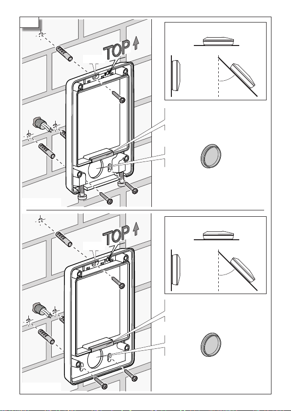
1
!
• XTR B INOX •
Ø 4 mm
Ø 4 mm
MAX 45°
Guarnizione di tenuta IP • IP sealing gasket
• Joint d'étanchéité IP • IP Dichtung • Junta
de estanqueidad IP • IP-afdichting
Ø 15 mm
Guarnizione di tenuta IP • IP sealing gasket
• Joint d'étanchéité IP • IP Dichtung • Junta
de estanqueidad IP • IP-afdichting
!
MAX 45°
Ø 15 mm
• XTR B •
XTR B 02 532109 - Rev.A
Page 5
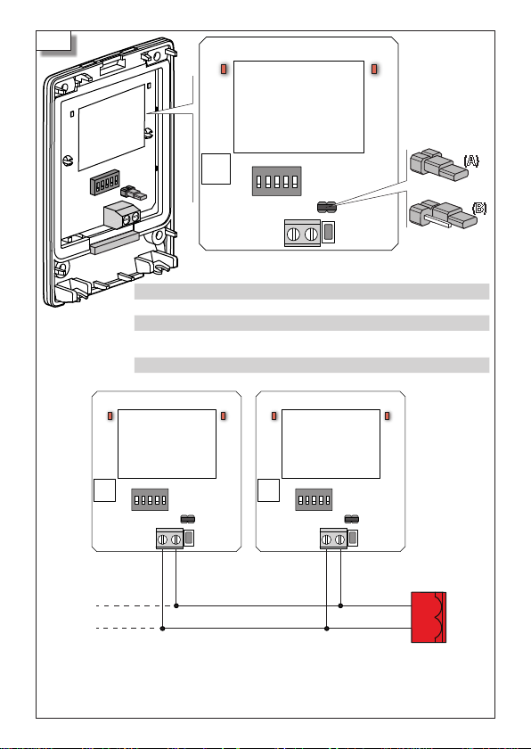
2
DL2 DL3
BZ1
SW1
ON
1 2 3 4 5
Dip-switch • Dip-switch • Dip-switch • Dip-Schalter • Dip-switch • DIP-schakelaar
SW1
Pulsante • Button • Bouton • Taste • Botón • Drukknop
SW2
Jumper • Jumper • Jumper • Jumper • Jumper • Jumper
J5
BUS 2easy Morsetti • BUS 2easy Terminals • BUS 2easy bornes • BUS 2easy Klemmen •
J7
BUS 2easy Bornes • BUS 2easy Aansluitklemmen
Buzzer • Buzzer • Buzzer • Buzzer • Zumbador • Buzzer
BZ1
Led • LED • Led • LED • Led • Led
DL2 DL3
J5
J7
SW2
(A)
(B)
DL2 DL3
BZ1
SW1
ON
1 2 34 5
J5
J7
SW2
DL2 DL3
BZ1
SW1
ON
1 2 34 5
J5
J7
SW2
BUS 2easy
MAX 100 m
- 0.5 mm2 Sezione MAX dei cavi • MAX section of cables • Section MAX des câbles • MAX Querschnitt der
Kabel • Sección MÁX. de los cables • MAX doorsnede kabels
- La linea BUS non ha polarità • The BUS line does not require a matching polarity connection • La ligne
BUS n'a pas de polarité • Die BUS Leitung hat keine Polarität • La línea BUS no tiene polaridad • De
BUS-lijn heeft geen polariteit
XTR B 03 532109 - Rev.A
Page 6
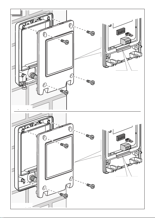
3
• XTR B INOX •
Guarnizione di tenuta IP • IP
sealing gasket • Joint d'étanchéité IP • IP Dichtung • Junta de
estanqueidad IP • IP-afdichting
Guarnizione di tenuta IP • IP
sealing gasket • Joint d'étanchéité IP • IP Dichtung • Junta de
estanqueidad IP • IP-afdichting
• XTR B •
XTR B 04 532109 - Rev.A
Page 7
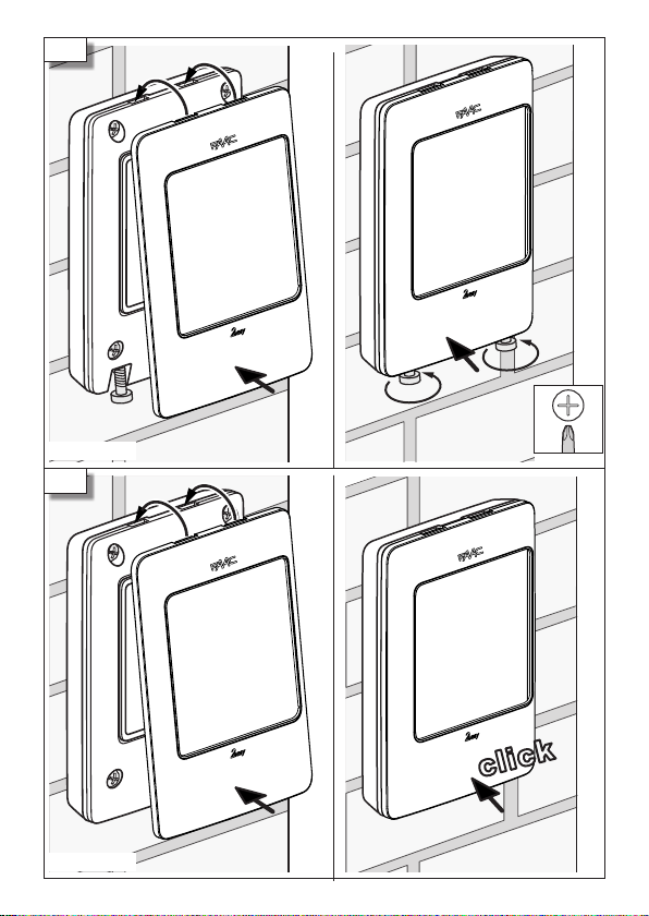
4
• XTR B INOX •
5
5
click
• XTR B •
XTR B 05 532109 - Rev.A
Page 8

6
DL2 DL3
SW1
BZ1
J7
J5
SW2
ON
1 2 34 5
DL2 DL3
SW1
BZ1
DL2 DL3
SW1
BZ1
J7
J5
SW2
ON
1 2 34 5
DL2 DL3
SW1
BZ1
A
7
- 1CH max 14 XTR B
- 2CH max 4 XTR B
XTR B (A)
B
A
XTR B (B)
A
BUS-RELAY 4CHBUS 2easy BUS-RELAY 2CH
1CH/2CH max 4 XTR B
XTR B (1CH)
R1
R2
R3
R4
Tag-Group1
Tag-Group2
Tag-Group3
Tag-Group4
B
B
R1
R2
R1
R2
R3
R4
XTR B 06 532109 - Rev.A
XTR B (2CH)
Tag-Group1
Tag-Group2
R1
R2
R3
R4
Page 9

Translation of the original instructions
EN
CE DECLARATION OF CONFORMITY
The Manufacturer
Company name: FAAC S.p.A. Soc. Unipersonale
Address: Via Calari, 10 - 40069 Zola Predosa BOLOGNA - ITALY
hereby declares on his sole responsibility that the following products:
Description: Tag reader
Models:
XTR B, XTR B INOX
comply with the following applicable EU legislations:
RED Directive 2014/53/EU
ROHS 2 Directive 2011/65/EU
Furthermore, the following harmonised standards have been applied:
EN 60950-1:2006 + A11:2009 + A1:2010 + A12:2011 + A2:2013
EN 62311:2008
EN 301 489-1 V1.9.2 + EN 301 489-3 V1.6.1
EN 302 291-2 V1.1.1
Bologna, 01-01-2017 CEO
CONTENTS
1. XTR B ....................................................................................................... 2
Technical data
........................................................................................... 3
2. SAFET Y INFORMATION ...................................................................................4
3. INSTALLATION .............................................................................................4
3.1 Connecting to the board with BUS 2easy ..............................................................5
Configuring the dip-switches
First storage of Tags
3.2 Connecting to a BUS-RELAY interface ..................................................................7
Configuring the dip-switches
Assigning the Tags to the Relays
First s torage of a Tag-Group
.......................................................................... 5
.................................................................................... 6
.......................................................................... 7
....................................................................... 7
........................................................................... 8
4. DELETING ALL TAGS ....................................................................................... 9
5. DELETING A TAG GROUP ..................................................................................9
6. TROUBLESHOOTING .................................................................................... 10
7. REPLACING THE XTR B .................................................................................. 10
8. USAGE .................................................................................................... 11
1CH mode: 1 comman d
2CH mode: 2 commands
................................................................................11
...............................................................................11
9. ADDING TAGS ............................................................................................ 13
10. MAINTENANCE ......................................................................................... 13
XTR B 1 532109 - Rev.A
Page 10

1. XTR B
The XTR B Tag reader is included in the range of
BUS 2easy control devices. The range also includes,
for example, key operated switches and key pads
(see catalogue).
The XTR B only recognises dedicated FAAC Tags
(see catalogue). A limited number of Tags can
be enabled.
Connection
. The XTR B can be connected to:
- Electronic board with BUS 2easy
- BUS-RELAY 2CH interface
- BUS-RELAY 4CH interface
When the XTR B is switched on, it automatically
recognises the type of connection.
The boards with BUS 2easy that are compatible or incompatible with the XTR B are indicated
below. Some boards are compatible only if the
firmware has been updated to the versions indicated
(FW) or later (refer to the instructions of the updated
boards) The boards with BUS 2easy that are not
listed are always compatible.
Compatible boards [revision] FW
E045 [previous to 1L] 1.7
E045 [1L and later] 3.2
E145 [previous to 1R] 2.0
E145 [1R and later] 3.2
E124 [all] 3.2
E721 [all] 2.9
624BLD [all] 2.1
E680 [all] 2.1
JE275 [all] 2.1
Incompatible boards: E700, E720, E024, E391
, E012S, E850.
Operation. The Tag transmits its code when brought
close to the reader. When the reader recognises
an enabled Tag, it transmits the command via the
BUS 2easy line.
The XTR B works in the mode set via the dip-switches
on the device. The choice is between:
- Single channel (XTR B_1CH) the Tag has only
1 command
- Two-channel (XTR B_2CH) the Tag has 2
commands
With the XTR B_2CH, the activation of the first or
second command depends on the mode in which
the Tag is used on the reader (see § 8).
The Tag can be used for an impulse command or a
maintained action command.
XTR B 2 532109 - Rev.A
This device cannot be used as an emer-
!
gency stop.
This device cannot be used as the maintained command in the dead-man mode
of operation.
. If the XTR B is connected to the
Commands
BUS 2easy of a board, the commands are defined
by the dip-switches on the reader. If the XTR B
is connected to a BUS-RELAY interface, the relay
outputs must be associated with the Tags at the
time they are stored.
First storage procedure
to the installer and must be carried out in order
to enable the first Tag and to store its code on the
reader. Other Tags can be stored before finishing
the procedure.
All Tags enabled during the First storage procedure
are Master tags.
Add Tags
. This procedure allows additional Tags
to be enabled subsequently to the first storage
procedure.
In order to add additional Tags, you must have a
Master Tag that has already been stored and be close
to the reader (without having to open it).
Tags can be added as either Master or Slave tags.
Slave tags cannot be used to enable the addition
of Tags.
XTR B_A/XTR B_B
distinct codes: A and B. The position of the jumper
on the reader determines whether the reader recognises code A or code B. In this way, a Tag can be
enabled with code A on one system and code B on
another system. For example: A Tag enabled with
code A on the XTR B of a condominium entrance
and with code B on the XTR B of a private entrance.
. This procedure is restricted
. Each tag always transmits two
Page 11

Connection type Mode (§ Dip-switch con-
Board with BUS 2easy
BUS-RELAY 4CH interface
BUS-RELAY 2CH interface
TECHNICAL DATA
power supply BUS 2easy line
MAX power consumption 50 mA
ingress protection IP 54
operating temperature -20°C +55°C
dimensions 100 x 72 x 21 mm
Tag format ISO15693
Symbols used in the instructions
! Risk of personal injury or damage to
components
F electrocution hazard
§ chapter/section: e.g. § 1 = Chap.1
figure: e.g. 1 = Fig.1
page: e.g. 1 = Page 1
table: e.g. 1 = Tab.1
1CH single channel ; 2CH two-channel
time indicator
(BEEP) Audible signal
Led off Led on
Flashing Fast flashing
figuration)
1CH
2CH
1CH
2CH
1CH
2CH
No. of control devices that can be connected
max 14*
max 4*
max 4*
max 4*
max 4*
max 2*
* Theoretical no.: The actual
number of control devices that
can be connected depends on the
total absorbed power of all the
accessories and the maximum
current that can be supplied by
the board.
XTR B 3 532109 - Rev.A
Page 12

2. SAFET Y INFORMATION
The packaging materials (plastic, polysty-
!
rene, etc.) must not be left within reach
of children as they are potential sources
of danger.
Always switch off the electricity supply
F
before making electrical connections.
When you have finished with them, dis-
pose of the packaging in the appropriate
containers, as per applicable waste disposal
regulations.
The electronic components must not be
disposed of in landfill, but should be taken
to an authorised disposal and recycling
centre, in compliance with applicable waste
disposal legislation.
3. INSTALLATION
1. Prepare the connecting cables and install the
base. Follow the instructions in 1.
2. Connect to the BUS 2easy terminals on the
board or the BUS-RELAY interface. Follow the
instructions in 2.
3. Position the jumper to specify reader A or B:
- J5 closed = XTR B_A
- J5 open = XTR B_B
4. Configure the dip-switches according to the
connection:
- Board with BUS 2easy: see § 3.1
- BUS-RELAY interface: see § 3.2
5. Switch power on to the electronic board with
BUS 2easy or the BUS-RELAY interface.
- The XTR B flashes once, then the LEDs turn
off: XTR B in standby.
6. Register the BUS 2easy devices (see board or
interface instructions).
7. Carry out the first storage procedure according to
the type of connection:
- Board with BUS 2easy: see 6
- BUS-RELAY interface: see 8
8. Make sure that all tags are working correctly for
all enabled commands.
9. Fasten the body to the base (3) and put the
cover on (4- 5).
The IP sealing gaskets in the base and in the
!
body must be fitted and intact.
XTR B 4 532109 - Rev.A
Page 13

3.1 CONNECTING TO THE BOARD WITH
BUS 2EASY
CONFIGURING THE DIPSWITCHES
Position the dip-switches (
to specify:
- 1CH or 2CH mode of operation (Dip-switch 5)
- the commands that the XTR B transmits to the
board (Dip-switches 1-2-3-4)
For each control device connected to the
!
BUS 2easy line, position the dip-switches so
that a command is used only on one device.
In order to add an XTR B to an existing sys-
tem you must know which commands are
already used on the other BUS 2easy devices
that are present. See the instructions for
the devices that are already installed in
1 or 2) in order
order to identify which commands are already
used. For future reference, you can make a
note of the IDs of the installed devices in
the table at the end of this manual. Any
BUS 2easy photocells or BUS 2easy safety
edges do not interfere with the control devices. Their dip-switches can be ignored.
1 1CH mode
ON
1 2 3 4 5
Dip-switch
1 2 3 4
0 0 0 0 Open A_1
0 0 0 1 Open A_2
0 0 1 0 Open A_3
0 0 1 1 Open A_4
0 1 0 0 Open A_5
0 1 0 1 Stop
0 1 1 0 Stop NC*_1
0 1 1 1 Stop NC*_2
1 0 0 0 Close
1 0 0 1 Open B_1
1 0 1 0 Open B_2
1 0 1 1 Open B_3
1 1 0 0 Open B_4
1 1 0 1 Open B_5
1 1 1 0 not used
1 1 1 1 not used
* Stop NC, also generates a Stop when the XTR B is disconnected.
XTR B 5 532109 - Rev.A
Dip 5 = OFF
command
2 2CH mode
ON
1 2 3 4 5
Dip-switch
1 2 3 4
0 0 0 0 Open A_1 Open B_1
0 0 0 1 Open A_1 Open B_2
0 0 1 0 Open A_1 Stop
0 0 1 1 Open A_1 Close
0 1 0 0 Open A_2 Open B_1
0 1 0 1 Open A_2 Open B_2
0 1 1 0 Open A_2 Stop
0 1 1 1 Open A_2 Close
1 0 0 0 Open A_3 Open B_3
1 0 0 1 Open A_3 Open B_4
1 0 1 0 Open A_3 StopNC*_1
1 0 1 1 Open A_3 Close
1 1 0 0 Open A_4 Open B_3
1 1 0 1 Open A_4 Open B_4
1 1 1 0 Open A_4 StopNC*_2
1 1 1 1 Open A_4 Close
1 = ON ; 0 = OFF
Dip 5 = ON
Command 1 Command 2
Page 14

FIRST STORAGE OF TAGS
The XTR B must be in standby. The memory must
be empty.
1. Press and release the button once.
- After 2 s, the XTR B will BEEP once and flash once.
- It will flash for 20 s (storing enabled).
2. Bring the first Tag up to the reader.
- The XTR B will BEEP once and the LEDs will come
on for 2 s: the Tag is enabled.
- Flashing will resume for 10 s (storing enabled).
3. Repeat step 2 for any additional Master Tags
required.
4. To finish, let 10 s pass without bringing any
new Tags up to the reader (or press the button
immediately).
- The LEDs turn off: XTR B in standby.
Errors during storage process Solution
During step 1, the XTR B signals
an error and turns off in standby:
the button has been pressed
more than once
During step 1, the XTR B signals
an error and turns off in standby:
the memory is not empty
During step 3, the XTR B signals
an error, then the LEDs turn off:
the Tag has not been stored
ERROR warning: Five BEEPS and 5 flashes
in quick succession.
Repeat the process correctly
Carry out the "Add
Tag" or "Total Deletion" process
Carry out the "Add
Tag" process
FIRST STORAGE PROCEDURE
1
2 s 1() , 20 s (timeout)
... 20 s MAX
2
1+2 s: Tag OK , 10 s (timeout)
...
10 s MAX
3
1+
4
timeout without Tag: END
SW2
2 s: Tag OK , 10 s timeout
SW2
First Master Tag
Additional Master Tags
XTR B 6 532109 - Rev.A
Page 15

3.2 CONNECTING TO A BUSRELAY
INTERFACE
CONFIGURING THE DIPSWITCHES
Position the dip-switches ( 3 ) in order to specify:
- 1CH or 2CH mode of operation (Dip-switch 5)
- ID device identifier (Dip-switches 1-2)
Dip-switches 3-4 are irrelevant.
Each control device connected to the BUS
!
line must have a different ID.
In order to add an XTR B to an existing
system you must know the IDs of the other
BUS 2easy devices that are present. See
the instructions for the devices already
installed in order to identify the IDs that
have already been used.
For future reference, you can make a note of
the IDs of the installed devices in the table
at the end of this manual.
ASSIGNING THE TAGS TO THE RELAYS
In single channel mode (1CH), each enabled Tag can
activate only one relay. The relay is assigned during
the storage phase by selecting a Group.
In two channel mode (2CH), each enabled Tag can
activate 2 relays (not simultaneously). The pair
of relays is assigned during the storage phase by
selecting a Group. The Tag activates one relay with
command 1 and the other with command 2 (see § 8).
3 ID in 1CH or 2CH mode
ON
1 2 3 4 5
Dip-switch
1 2 3 4
0 0 x x ID1 1 , 2 , 3 , 4 1 , 2
0 1 x x ID2 1 , 2 , 3 , 4 1 , 2
1 0 x x ID3 1 , 2 , 3 , 4 1
1 1 x x ID4 1 , 2 1
1 = ON ; 0 = OFF ; x = irrelevant
XTR B 7 532109 - Rev.A
Groups available in 1CH mode Groups available in 2CH mode
ID
CORRESPONDENCE BETWEEN GROUP/RELAY
Group 1
Group 2
Group 3
Group 4
ON
Dip 5 = OFF
1CH
1 2 3 4 5
XTR B (1CH) Relay 1
XTR B (2CH)
Command 1 Relay 1
Command 2 Relay 2
XTR B (1CH) Relay 2
XTR B (2CH)
Command 1 Relay 3
Command 2 Relay 4
XTR B (1CH) Relay 3
XTR B (1CH) Relay 4
Dip 5 = ON
2CH
Page 16

FIRST STORAGE OF A TAGGROUP
The XTR B must be in standby. The memory of the
Group selected must be empty.
1. Select the group: press the button the same
number of times as the number of the Group
(eg.: Group 3, press 3 times).
- After 2 s, the XTR B will BEEP and flash the same
number of times as the number of the Group.
- It will flash for 20 s (storing enabled).
2. Bring the Tag close to the reader.
- The XTR B will BEEP the same number of times as
the number of the Group and the LEDs will come
on for 2 s: the Tag is enabled.
- Flashing will resume for 10 s (storing enabled).
3. Repeat step 2 for any additional Master Tags that
are required for the Group.
- The XTR B will BEEP once and the LEDs will
come on for 2 s after each additional Tag has
been enabled.
4. To finish, let 10 s pass without bringing any
new Tags up to the reader (or press the button
immediately).
- The LEDs turn off: XTR B in standby.
Repeat the procedure to enable one or more tags of
another Group. At step 1, assign an available Group.
Errors during storage process Solution
During step 1, the XTR B signals
an error, then the LEDs turn off:
Group not available
During step 1, after a BEEP or series of BEEPS equal to the group
number, XTR B memorisation is
not active (LEDs on, NO flashing
for 20 secs): the group is already
stored in the memory
During step 3, the XTR B signals
an error, then the LEDs turn off:
the Tag has not been stored in
the memory
ERROR warning: Five BEEPS and 5 flashes
in quick succession.
Repeat the process
correctly
Carry out the “Add
Tag” process for
the group
Carry out the “Add
Tag” process for
the group
FIRST STORAGE OF A Tag-GROUP
N
times (N = Group number)
1
SW2
2 s N () , 20 s (timeout)
... 20 s MAX
2
N +2 s: Tag OK , 10 s (timeout)
...
10 s MAX
3
1+
4
timeout without Tag: END
2 s: Tag OK , 10 s timeout
SW2
First Master Tag of the Group
Additional Master Tag of
the Group
XTR B 8 532109 - Rev.A
Page 17

4. DELETING ALL TAGS
This procedure permanently deletes all Tags from memory.
!
The XTR B must be in standby.
1. Press and hold the button throughout the entire
sequence:
- After 2 s the XTR B will BEEP once and starts to
flash for 10 s. The frequency of flashing then
increases for another 10 s. Finally the XTR B will
BEEP once and the LEDs turn on for 1 s: the Tags
have been deleted.
- The LEDs turn off: XTR B in standby.
2. Release the button.
To interrupt the deletion procedure, release the
button before the BEEP in step 1
off: XTR B in standby.
. The LEDs turn
1
2 s 1 , 10 s , 10 s ,
1 + 1 s ,
2
SW2
SW2
TOTAL DELETION
~20 s
5. DELETING A TAG GROUP
This procedure permanently deletes all the Tags of the Group. The procedure is only active if the
!
XTR B is connected to a BUS-RELAY interface. In other cases, carry out the Total Deletion procedure
The XTR B must be in standby.
1. Select the Group to delete: press the button
the same number of times as the number of the
Group (e.g.: Group 3, press 3 times).
- After 2 s, the XTR B will BEEP and flash the
same number of times as the number of the
Group. Then the LEDs will turn on steadily.
2. Press and hold the button throughout the entire
sequence:
- The XTR B will BEEP once and starts to flash for
10 s. The frequency of flashing then increases
for another 10 s. Finally the XTR B will BEEP
once and the LEDs turn on for 1 s: the Group has
been deleted.
- The LEDs turn off: XTR B in standby.
3. Release the button.
To interrupt the deletion procedure, release the
button before the BEEP in step 2
off: XTR B standby.
Note
: If the XTR B signals an error at stage 1 and
then the LEDs turn off, carry out the total deletion
procedure.
. The LEDs turn
1
2 s N ( ) ,
2
1
3
DELETING a GROUP
N times (N = Group number)
SW2
SW2
, 10 s , 10 s , 1 + 1 s ,
SW2
~ 20 s
SW2
XTR B 9 532109 - Rev.A
Page 18

6. TROUBLESHOOTING
Indication Explanation Necessary action
The LEDs do not light up when
it is switched on.
When switched on, the LEDs
flash continuously.
When switched on, the XTR B
gives an error.
When a Tag is brought close to
the XTR B it does not activate
the command.
An enabled Tag brought up to
the XTR B does not activate
the command, the LEDs flash
continuously.
No power or the XTR B is not
working.
Connection error. Check the connection.
Corrupted data in memory. Carry out the Total Deletion and the First
No power or the XTR B is not
working.
The Tag is not enabled.
Dip-switch configuration
error.
Check that the power supply is connected
and live. If there are no errors, replace
the XTR B.
storage procedure.
Check that the power supply is connected
and live. If there are no errors, carry out
the Add Tag procedure.
Check the configuration of the dip-switches
for all BUS 2easy control devices that are
connected in order to eliminate BUS 2easy
address conflicts.
7. REPLACING THE XTR B
In the event of replacement, you can avoid having to repeat the storage procedure for all previously enabled
Tags. A Master Tag that was stored on the previous XTR B is required.
New XTR B connected to the BUS 2easy board.
1. Press and release the button once.
- After 2 s, the XTR B will BEEP once and flash
once. Then it will flash for 20 s.
2. Press and release the button.
- The XTR B will BEEP once and the frequency of
the flashes will increase.
3. Within 10 s, bring up a Master Tag already stored
on the previous XTR B.
- The XTR B will BEEP once and the LEDs will
come on for 2 s.
4. Press the button to finish. The LEDs turn off:
XTR B in standby.
New XTR B connected to the BUS-RELAY interface
1. Select the group: press the button the same
number of times as the number of the Group
(eg.: Group 3, press 3 times).
- After 2 s, the XTR B will BEEP and flash the
same number of times as the number of the
Group. Then it will flash for 20 s.
2. Press and release the button.
- The XTR B will BEEP once and the frequency of
the flashes will increase.
3. Within 10 s, bring up a Master Tag already stored
on the previous XTR B.
- The XTR B will BEEP and flash the same number
of times as the number of the Group and the LEDs
will come on for 2 s, then flashing resumes.
4. Press the button to finish. The LEDs turn off:
XTR B in standby.
Repeat for all Tag Groups present.
XTR B 10 532109 - Rev.A
Page 19

8. USAGE
1CH MODE: 1 COMMAND
1. Bring the Tag up to the reader in standby:
- The XTR B will BEEP once and the LEDs will come
on steadily
2. Give an impulse or maintained action command.
A. Impulse command: move the Tag away im-
mediately.
B. Maintained action command: move the Tag
away only when you wish to stop the command.
When the Tag is moved away, the LEDs turn off.
Impulse command in Single channel mode
1
1 +
Command , 1 + Maintained action command ,
2CH MODE: 2 COMMANDS
Impulse command 1
1. Bring the Tag up to the reader in standby:
- The XTR B will BEEP once; the LEDs come on stead-
ily.
2. Move the Tag away within 2 s .
- The command is activated; the LEDs turn off.
1
1 +
Impulse command 1
... 2 s MAX
Command 1 ,
Maintained action command in Single channel mode
1
...
Impulse command 2
1. Bring the Tag close to the reader in standby and
hold it there.
- The XTR B will BEEP once; the LEDs come on
steadily.
- after 2 s, the XTR B will BEEP twice and flash
twice.
2. Move the Tag away within 2 s .
- The command is activated; the LEDs turn off.
1
1 + , ... 2 s 2 ( )
2
Impulse command 2
... ~ 2 s
... 2 s MAX
2
...
STOP
Command 2
XTR B 11 532109 - Rev.A
Page 20

Maintained action command 1
1. Bring the Tag close to the reader in standby and
hold it there:
- The XTR B will BEEP once and the LEDs will
come on steadily
- after 2 s, the XTR B will BEEP twice and flash
twice.
- after 2 s, the XTR B will BEEP 3 times and flash 3
times, then the LEDs will come on steadily
- after 3 s, the maintained action command is
activated
2. Move the Tag away when you wish to stop the
command, the LEDs turn off.
Maintained action command 1 Maintained action command 2
1
Maintained action command 2
1. Bring the Tag close to the reader in standby and
hold it there:
- The XTR B will BEEP once and the LEDs will
come on steadily
- after 2 s, the XTR B will BEEP twice and flash twice
- after 2 s, the XTR B will BEEP 3 times and flash 3
times, then the LEDs will come on steadily
2. Move the Tag away within 2 s and bring it back
to the reader within 5 s:
- The XTR B flashes once and the maintained action
command is activated
3. Move the Tag away when you wish to stop the
command, the LEDs turn off.
1
... ~ 9 s
,
1 +
2 s , 2 ( ) ,
2 s , 3 ( ) , ,
3 s Maintained action command 1
2
...
STOP
1 + ,
2 s , 2 ( ) ,
2 s , 3 ( ) ,
2
, Maintained action command 2
1
3
2 s MAX
... ~ 6 s
...
5 s MAX
...
XTR B 12 532109 - Rev.A
STOP
Page 21

9. ADDING TAGS
You must have a Master Tag that has already been
stored and be close to the XTR B (without having
to open it).
If the XTR B is connected to a BUS-RELAY
interface, use a Master Tag of the required
Group.
The XTR B must be in standby.
1. Bring a Tag that has NOT been stored up to the
reader and wait for about 5 s:
- The XTR B will BEEP twice and FLASH twice, then
the LEDs will come on steadily.
2. Move the Tag away.
3. Bring the previously stored Master Tag up to the
reader within 10 s.
- The LEDs still remain steady, the XTR B will
BEEP once.
4. Choose whether to add Master or Slave tags:
move the Master Tag
away within 5 s: MASTER
tags will be added.
- It will flash for 10 s (storing enabled).
5. Bring the Tags to add up to the reader in se-
quence, within 10 s of each other. The XTR B
will BEEP once and the LEDs turn on for 1 s for
each Tag added.
6. To finish, let 10 s pass without bringing a new
Tag up to the reader.
- The LEDs turn off: XTR B in standby.
wait until the XTR B
BEEPS twice, then move
the Master tag away:
SLAVE tags will be added.
1
2 () ,
2
... 10 s ( timeout)
3
1
4
- MASTER - SLAVE
ADDING TAGS
~ 5 s
Tag NOT stored
Master Tag already stored
< 5 s
4
> 5 s
2
10 s (timeout)
... 10 s MAX
5
Tag to add
10. MAINTENANCE
Clean the outer surfaces only with a soft cloth Do not
use detergents or oils.
XTR B 13 532109 - Rev.A
1 s: Tag OK , 10 s timeout
1 +
timeout without Tag: END
6
Page 22

ID dispositivo • Device ID •
ID dispositif • Geräte-ID •
ID dispositivo • ID apparaat
Comando • Command •
Commande • Steuerung •
Comando • Commando
1
2
3
4
1
2
3
4
1
2
3
4
1
2
3
4
Note • Notes • Remarques • Anmerkung •
Notas • Opmerkingen
1
2
3
4
XTR B 14 532109 - Rev.A
Page 23

ID dispositivo • Device ID •
ID dispositif • Geräte-ID •
ID dispositivo • ID apparaat
Comando • Command •
Commande • Steuerung •
Comando • Commando
1
2
3
4
1
2
3
4
1
2
3
4
1
2
3
4
Note • Notes • Remarques • Anmerkung •
Notas • Opmerkingen
1
2
3
4
XTR B 15 532109 - Rev.A
Page 24

FAAC S.p.A. Soc. Unipersonale
Via Calari, 10 - 40069 Zola Predosa BOLOGNA - ITALY
Tel. +39 051 61724 - Fax +39 051 758518
www.faac.it - www.faacgroup.com
XTR B 16 532109 - Rev.A
 Loading...