

Page 1
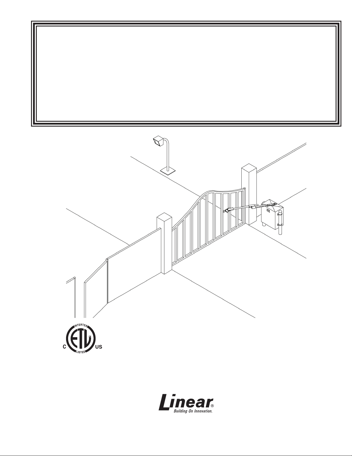
SWG
Swing Gate Operator
Installation Guide
Operator models contained in this manual
conform to UL325 standard for use in
Class I, II, III, and IV applications
USA & Canada (800) 421-1587 & (800) 392-0123
(760) 438-7000 - Toll Free FAX (800) 468-1340
www.linearcorp.com
Page 2
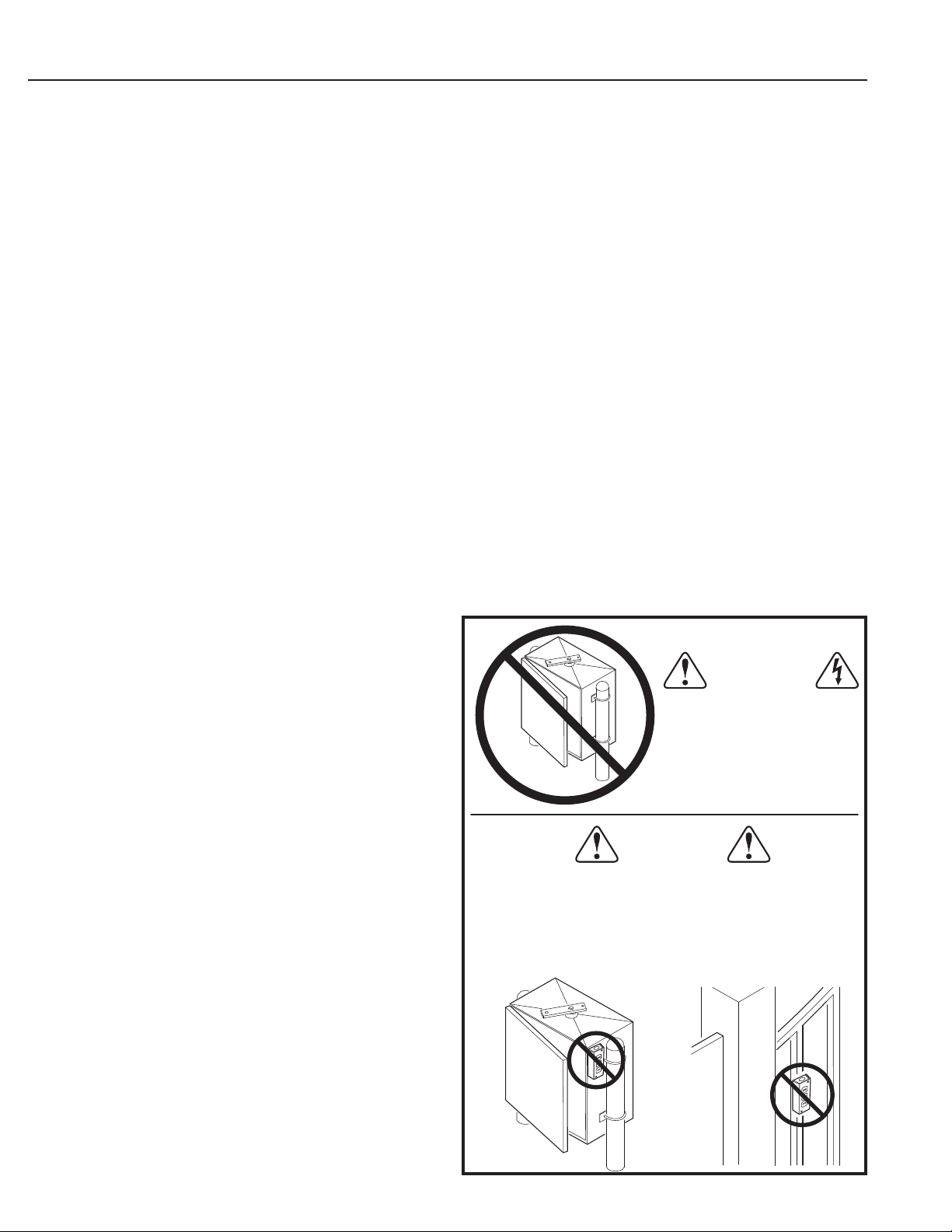
Table of Contents
Pre-installation Information . . . . . . . . . . . . . . . . . . . . . . . . . . . . . . . . . . 1
Before You Begin... . . . . . . . . . . . . . . . . . . . . . . . . . . . . . . . . . . . . . .1
Always Check the Gate’s Action . . . . . . . . . . . . . . . . . . . . . . . . . . . . 1
Gate Operator Classifi cations . . . . . . . . . . . . . . . . . . . . . . . . . . . . . .1
Approved Obstruction Detection Devices . . . . . . . . . . . . . . . . . . . . . 1
Safety Information and Warnings . . . . . . . . . . . . . . . . . . . . . . . . . . . . . .1
Regulatory Warnings . . . . . . . . . . . . . . . . . . . . . . . . . . . . . . . . . . . . . 1
Wiring Specifi cations . . . . . . . . . . . . . . . . . . . . . . . . . . . . . . . . . . . . . . . 2
AC Power Wiring . . . . . . . . . . . . . . . . . . . . . . . . . . . . . . . . . . . . . . . .2
DC Control and Accessory Wiring . . . . . . . . . . . . . . . . . . . . . . . . . . . 2
Mounting Pad Installation . . . . . . . . . . . . . . . . . . . . . . . . . . . . . . . . . . . . 3
Gate Preparation . . . . . . . . . . . . . . . . . . . . . . . . . . . . . . . . . . . . . . . .3
Mounting Specifi cations . . . . . . . . . . . . . . . . . . . . . . . . . . . . . . . . . .3
Operator Preparation . . . . . . . . . . . . . . . . . . . . . . . . . . . . . . . . . . . . . . .4
Vent Plug Installation . . . . . . . . . . . . . . . . . . . . . . . . . . . . . . . . . . . . .4
Gate Arm Installation . . . . . . . . . . . . . . . . . . . . . . . . . . . . . . . . . . . . . . .4
Crank Extension Installation . . . . . . . . . . . . . . . . . . . . . . . . . . . . . . .4
Overtravel Stop Installation . . . . . . . . . . . . . . . . . . . . . . . . . . . . . . . .4
Gate Plate Installation . . . . . . . . . . . . . . . . . . . . . . . . . . . . . . . . . . . .5
Choosing Good Harmonics . . . . . . . . . . . . . . . . . . . . . . . . . . . . . . . .5
Pipe Link Installation . . . . . . . . . . . . . . . . . . . . . . . . . . . . . . . . . . . . .5
Setting the Arm Lengths . . . . . . . . . . . . . . . . . . . . . . . . . . . . . . . . . .5
Operator Setup . . . . . . . . . . . . . . . . . . . . . . . . . . . . . . . . . . . . . . . . . . . .6
Controller Access . . . . . . . . . . . . . . . . . . . . . . . . . . . . . . . . . . . . . . .6
AC Power Connection . . . . . . . . . . . . . . . . . . . . . . . . . . . . . . . . . . . .6
Earth Ground . . . . . . . . . . . . . . . . . . . . . . . . . . . . . . . . . . . . . . . . . . . 6
Limit Cam Rough Adjustment . . . . . . . . . . . . . . . . . . . . . . . . . . . . . . 6
Torque Limiter Adjustment . . . . . . . . . . . . . . . . . . . . . . . . . . . . . . . . .7
Limit Cam Fine Adjustment . . . . . . . . . . . . . . . . . . . . . . . . . . . . . . . .7
Controller Features . . . . . . . . . . . . . . . . . . . . . . . . . . . . . . . . . . . . . . . . .8
Indicator Descriptions . . . . . . . . . . . . . . . . . . . . . . . . . . . . . . . . . . . . . . .9
Terminal Descriptions . . . . . . . . . . . . . . . . . . . . . . . . . . . . . . . . . . . . . . 10
Operator Accessory Connections . . . . . . . . . . . . . . . . . . . . . . . . . . . .11
Basic Controller Programming. . . . . . . . . . . . . . . . . . . . . . . . . . . . . . .12
Programming Overview . . . . . . . . . . . . . . . . . . . . . . . . . . . . . . . . . . 12
Entering Programming Mode . . . . . . . . . . . . . . . . . . . . . . . . . . . . .12
Exiting Programming Mode . . . . . . . . . . . . . . . . . . . . . . . . . . . . . . .12
Programming Keystrokes . . . . . . . . . . . . . . . . . . . . . . . . . . . . . . . .12
Left or Right Hand Operation. . . . . . . . . . . . . . . . . . . . . . . . . . . . . .12
Dual Gate Enable . . . . . . . . . . . . . . . . . . . . . . . . . . . . . . . . . . . . . .12
Auto Close Timer . . . . . . . . . . . . . . . . . . . . . . . . . . . . . . . . . . . . . . .12
Run Alarm and Pre-start Alarm . . . . . . . . . . . . . . . . . . . . . . . . . . . . 13
Maximum Open Direction Current Setting . . . . . . . . . . . . . . . . . . . . 13
Maximum Close Direction Current Setting . . . . . . . . . . . . . . . . . . .13
Advanced Controller Programming . . . . . . . . . . . . . . . . . . . . . . . . . . . 14
Entering Advanced Programming Mode . . . . . . . . . . . . . . . . . . . . .14
Maximum Run Time . . . . . . . . . . . . . . . . . . . . . . . . . . . . . . . . . . . .14
Single Button Input Setup . . . . . . . . . . . . . . . . . . . . . . . . . . . . . . . . 14
Stagger Mode . . . . . . . . . . . . . . . . . . . . . . . . . . . . . . . . . . . . . . . . .14
Stagger Delay Time . . . . . . . . . . . . . . . . . . . . . . . . . . . . . . . . . . . . .14
Auxiliary Relay Mode . . . . . . . . . . . . . . . . . . . . . . . . . . . . . . . . . . . .15
Reverse Delay Time . . . . . . . . . . . . . . . . . . . . . . . . . . . . . . . . . . . .15
Brake Delay Time . . . . . . . . . . . . . . . . . . . . . . . . . . . . . . . . . . . . . .15
Constant Pressure Mode . . . . . . . . . . . . . . . . . . . . . . . . . . . . . . . . .15
Shadow Loop Open Prevention . . . . . . . . . . . . . . . . . . . . . . . . . . . .15
Reset Cycle Count . . . . . . . . . . . . . . . . . . . . . . . . . . . . . . . . . . . . .16
Maintenance Alert Trigger . . . . . . . . . . . . . . . . . . . . . . . . . . . . . . . .16
Mid-travel Stop Position . . . . . . . . . . . . . . . . . . . . . . . . . . . . . . . . . . 16
Anti-tailgate Enable . . . . . . . . . . . . . . . . . . . . . . . . . . . . . . . . . . . . .16
Radio Enable . . . . . . . . . . . . . . . . . . . . . . . . . . . . . . . . . . . . . . . . . . 16
Antenna Installation . . . . . . . . . . . . . . . . . . . . . . . . . . . . . . . . . . . . . 16
Radio Transmitter Learn . . . . . . . . . . . . . . . . . . . . . . . . . . . . . . . . .17
Radio Transmitter Delete . . . . . . . . . . . . . . . . . . . . . . . . . . . . . . . . .17
MGT Obstacle Transmitter Learn . . . . . . . . . . . . . . . . . . . . . . . . . .17
MGT Obstacle Transmitter Delete . . . . . . . . . . . . . . . . . . . . . . . . . .17
Motor Type Selection . . . . . . . . . . . . . . . . . . . . . . . . . . . . . . . . . . . . 17
Reset Controller to Factory Defaults . . . . . . . . . . . . . . . . . . . . . . . .17
Loop Layout Illustration . . . . . . . . . . . . . . . . . . . . . . . . . . . . . . . . . . . .18
Safety Edge Layout Illustration . . . . . . . . . . . . . . . . . . . . . . . . . . . . . . 19
Photoeye Installation Illustration . . . . . . . . . . . . . . . . . . . . . . . . . . . . .20
Dual Gate Installations . . . . . . . . . . . . . . . . . . . . . . . . . . . . . . . . . . . . . 21
Optional In-Cabinet Heater . . . . . . . . . . . . . . . . . . . . . . . . . . . . . . . . . .21
Gate Operation . . . . . . . . . . . . . . . . . . . . . . . . . . . . . . . . . . . . . . . . . . . .22
Open Button . . . . . . . . . . . . . . . . . . . . . . . . . . . . . . . . . . . . . . . . . .22
Close Button . . . . . . . . . . . . . . . . . . . . . . . . . . . . . . . . . . . . . . . . . .22
Stop Button . . . . . . . . . . . . . . . . . . . . . . . . . . . . . . . . . . . . . . . . . . . 22
Single Input . . . . . . . . . . . . . . . . . . . . . . . . . . . . . . . . . . . . . . . . . . .22
Fire Department Input . . . . . . . . . . . . . . . . . . . . . . . . . . . . . . . . . . .22
Open Input . . . . . . . . . . . . . . . . . . . . . . . . . . . . . . . . . . . . . . . . . . . .22
Open Obstruction . . . . . . . . . . . . . . . . . . . . . . . . . . . . . . . . . . . . . .22
Close Obstruction . . . . . . . . . . . . . . . . . . . . . . . . . . . . . . . . . . . . . .22
Reverse Input . . . . . . . . . . . . . . . . . . . . . . . . . . . . . . . . . . . . . . . . .22
Open Loop . . . . . . . . . . . . . . . . . . . . . . . . . . . . . . . . . . . . . . . . . . . .22
Reverse Loop . . . . . . . . . . . . . . . . . . . . . . . . . . . . . . . . . . . . . . . . .22
Shadow/Reset Loop . . . . . . . . . . . . . . . . . . . . . . . . . . . . . . . . . . . .22
Operation Indications . . . . . . . . . . . . . . . . . . . . . . . . . . . . . . . . . . . . . .22
Power-up Display . . . . . . . . . . . . . . . . . . . . . . . . . . . . . . . . . . . . . . .22
Idle Condition . . . . . . . . . . . . . . . . . . . . . . . . . . . . . . . . . . . . . . . . .22
Last Gate Position/Condition . . . . . . . . . . . . . . . . . . . . . . . . . . . . . . 22
Pre-start Delay . . . . . . . . . . . . . . . . . . . . . . . . . . . . . . . . . . . . . . . .22
Reverse Delay . . . . . . . . . . . . . . . . . . . . . . . . . . . . . . . . . . . . . . . . .22
Run Timer . . . . . . . . . . . . . . . . . . . . . . . . . . . . . . . . . . . . . . . . . . . . 22
Error Indications . . . . . . . . . . . . . . . . . . . . . . . . . . . . . . . . . . . . . . . . . . 23
Entrapment . . . . . . . . . . . . . . . . . . . . . . . . . . . . . . . . . . . . . . . . . . .23
COMM LINK Connection Failure . . . . . . . . . . . . . . . . . . . . . . . . . . . 23
MGT Obstacle Transmitter Trouble . . . . . . . . . . . . . . . . . . . . . . . . .23
Maximum Run Time Exceeded . . . . . . . . . . . . . . . . . . . . . . . . . . . .23
How to Order Replacement Parts . . . . . . . . . . . . . . . . . . . . . . . . . .24
Troubleshooting . . . . . . . . . . . . . . . . . . . . . . . . . . . . . . . . . . . . . . . . . . .24
Contacting Technical Support . . . . . . . . . . . . . . . . . . . . . . . . . . . . .24
Operator fails to start . . . . . . . . . . . . . . . . . . . . . . . . . . . . . . . . . . . . 24
Motor operates, but gate does not move . . . . . . . . . . . . . . . . . . . . .24
Motor sounds like it is working harder than normal . . . . . . . . . . . . .24
Limit switch getting out of time . . . . . . . . . . . . . . . . . . . . . . . . . . . .24
Gate stopping part way open or closed . . . . . . . . . . . . . . . . . . . . . . 24
Gate staying open with automatic system . . . . . . . . . . . . . . . . . . . . 24
Preventative Maintenance . . . . . . . . . . . . . . . . . . . . . . . . . . . . . . . . . .25
General . . . . . . . . . . . . . . . . . . . . . . . . . . . . . . . . . . . . . . . . . . . . . . 25
Lubrication . . . . . . . . . . . . . . . . . . . . . . . . . . . . . . . . . . . . . . . . . . . . 25
6-Month Preventative Maintenance . . . . . . . . . . . . . . . . . . . . . . . . .25
FCC Notice . . . . . . . . . . . . . . . . . . . . . . . . . . . . . . . . . . . . . . . . . . . . . . .25
Model SWG Exploded View. . . . . . . . . . . . . . . . . . . . . . . . . . . . . . . . . .26
Single Phase Controller Parts List . . . . . . . . . . . . . . . . . . . . . . . . . . . .28
Three Phase Controller Parts List . . . . . . . . . . . . . . . . . . . . . . . . . . . .29
Gate Arm Assembly Parts List . . . . . . . . . . . . . . . . . . . . . . . . . . . . . . .30
Gate Operator Installation Checklist . . . . . . . . . . . . . . . . . . . . . . . . . .32
WARNING
ONLY QUALIFIED TECHNICIANS
SHOULD WORK ON
LINEAR SWING GATE
OPERATORS
WARNING
CONTROLS INTENDED FOR USER ACTIVATION MUST BE
LOCATED AT LEAST SIX FEET (6') AWAY FROM ANY MOVING
PART OF THE GATE AND WHERE THE USER IS PREVENTED
FROM REACHING OVER, UNDER, AROUND OR THROUGH THE
GATE TO OPERATE THE CONTROLS. OUTDOOR OR EASILY
ACCESSIBLE CONTROLS SHALL HAVE A SECURITY FEATURE
TO PREVENT UNAUTHORIZED USE.
SWG Swing Gate Operator Installation Guide
P1227 Revision X4 6-22-2011
- ii -
Page 3
Pre-installation Information
Before You Begin...
Before unpacking, inspect the carton for exterior damage. If
you fi nd damage, advise the delivery carrier of a potential
claim. Inspect your package carefully. You can check your
accessory box parts with the enclosed packing slip for your
convenience. Claims for shortages will be honored for only
30 days from the date of shipment.
Before installing the operator, read this manual completely to
ensure all requirements for proper installation are present. Verify
that the voltage to be used matches the voltage of the operator.
If you have any questions about the requirements for proper
installation of this gate operator contact technical support at
800-421-1587
Always Check the Gate’s Action
It’s very important before installing the gate operator to
make sure the gate’s swing is free and level throughout
the entire swing path. If the gate does not seem to
operate properly, it may affect the operator performance
or greatly shorten the life of the unit. The gate should
also be designed so that airfl ow is ample to prevent
wind resistance and drag.
Gate Operator Classifi cations
All gate operators can be divided into one of four different
classifi cations, depending on their design and usage. Install
this gate operator only when the operator is appropriate for
the construction and usage class as defi ned below:
• Class I Residential Vehicular Gate Operator
A vehicular gate operator intended for use in a home or for one to
four single family dwellings with a common garage or parking area
associated with these dwellings.
• Class II Commercial / General Access Vehicular Gate Operator
A vehicular gate operator intended for use in a commercial location or
building such as a multi-family housing unit of fi ve or more single family
units, hotel, retail store or other building servicing the general public.
• Class III Industrial / Limited Access Vehicular Gate Operator
A vehicular gate operator intended for use in an industrial location or
building such as a factory or loading dock area or other location not
intended to service the general public.
• Class IV Restricted Access Vehicular Gate Operator
A vehicular gate operator intended for use in a guarded industrial
location or building such as an airport security area or other restricted
access locations not servicing the general public, in which unauthorized
access is prevented via supervision by security personnel.
Approved Obstruction Detection Devices
The following contact or non-contact obstruction detection
devices have been approved for use with this swing gate
operator as part of a UL325 compliant installation:
• Contact Edges
Miller Edge Models MGO20, MGR20, MGS20, ME120
• Photoeyes
MMTC Model IR-55 (165’ range - P/N 2520-441)
MMTC Model E3K (28’ range - P/N 2520-031)
SWG Swing Gate Operator Installation Guide
Safety Information and Warnings
THE FOLLOWING FORMATS ARE USED FOR SAFETY NOTES
IN THESE INSTRUCTIONS.
CAUTION
This type of warning note is used to
indicate the possibility of damage to the
gate or gate operator.
WARNING
This type of warning note is used to
indicate possible mechanical hazards that
may cause serious injuries or death.
WARNING
This type of warning note is used to indicate
possible electrical shock hazards that may
cause serious injuries or death.
Regulatory Warnings
Read the following before beginning to install this swing
gate operator:
IMPORTANT INSTALLATION SAFETY INSTRUCTIONS
WARNING
TO REDUCE THE RISK OF SEVERE INJURY OR DEATH
TO PERSONS, REVIEW THESE INSTALLATION SAFETY
STEPS BEFORE PROCEEDING
1. READ AND FOLLOW ALL INSTALLATION INSTRUCTIONS.
2. Read the yellow “Safety Instructions” brochure enclosed with the
packet of information. If any pages are missing or are unreadable,
or you do not have the safety instructions, please call Linear at
1-800-421-1587 to request additional copies.
3. ALL ELECTRICAL CONNECTIONS TO THE POWER SUPPLY MUST
BE MADE BY A LICENSED ELECTRICIAN AND MUST OBSERVE ALL
NATIONAL AND LOCAL ELECTRICAL CODES.
4. A separate power-disconnect switch should be located near the
operator so that primary power can be turned off when necessary.
5. Install the enclosed warning signs on both sides of the gate. A
minimum of two (2) WARNING SIGNS shall be installed, one on each
side of the gate where easily visible.
6. Never reach between, through or around the fence to operate the
gate.
7. Never connect a button station within reach of the gate or on the
side of the gate operator.
8. Do not adjust the operator controller’s current sensing feature too
high. It should be adjusted high enough to keep the gate from falsely
triggering the sensing, but no higher than necessary for the gate to
operate. DO NOT DEFEAT THE PURPOSE OF THIS FUNCTION!
9. You must install all required safety equipment.
10. UL325 Compliance requires the use of contact edges or photoelectric
controls on all automatic or remotely-controlled gate operators.
11. The operator is intended for installation only on gates used for
vehicles. Pedestrians must be supplied with a separate access
opening. The pedestrian access opening shall be designed to
promote pedestrian usage. Locate the gate such that persons will
not come into contact with the vehicular gate during the entire path
of travel of the vehicular gate.
P1227 Revision X5 2-13-2013
- 1 -
Page 4
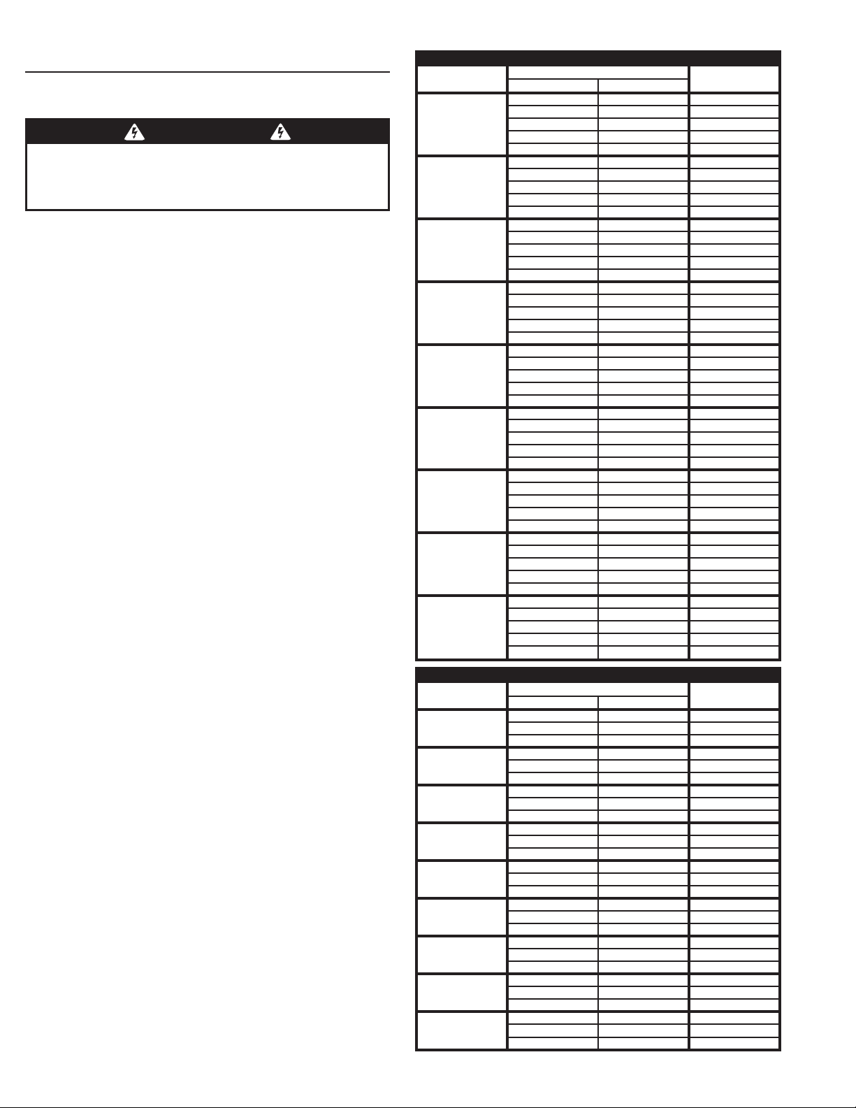
Wiring Specifi cations
Refer to the following steps for details on power and
accessory wiring for the operator.
WARNING
ALL AC ELECTRICAL CONNECTIONS TO THE POWER SOURCE AND
THE OPERATOR MUST BE MADE BY A LICENSED ELECTRICIAN
AND MUST OBSERVE ALL NATIONAL AND LOCAL ELECTRICAL
CODES.
USE COPPER WIRE ONLY!
AC Power Wiring
1. Find the listing on this page corresponding to the model, voltage and
horsepower rating of your operator.
2. The distance shown in the table is measured in feet from the
operator to the power source. DO NOT EXCEED THE MAXIMUM
DISTANCE. These calculations have been based on standard 115 V
and 230 V supplies with a 10% drop allowable. If your supply is under
the standard rating, the runs listed may be longer than what your
application will handle, and you should not run wire too near the
maximum distance for the gauge of wire you are using.
3. When large-gauge wire is used, a separate junction box (not
supplied) may be needed for the operator power connection.
4. Wire length calculations are based on the National Electrical Code,
Article 430 and have been carefully determined based on motor
inrush, brake solenoids, and operator requirements.
5. Connect power in accordance with local codes. The green ground
wire must be properly connected.
6. Wire insulation must be suitable to the application.
7. Electrical outlets are supplied in all 115 VAC models for convenience
with occasional use or low power consumption devices only. If
you choose to run dedicated equipment from these devices, it will
decrease the distance for maximum length and the charts will no
longer be accurate.
DC Control and Accessory Wiring
1. All control devices are now 24 VDC, which can be run up to 2000
feet with 14 AWG wire.
2. Control wiring must be run in a separate conduit from power wiring.
Running them together may cause interference and faulty signals in
some accessories.
3. A three-wire shielded conductor cable is required to connect two
operators together for dual operation. You must use Belden 8760
Twisted Pair Shielded Cable (or equivalent) only – P/N 2500-1982,
per foot). See Page 21 for details of this connection. Note: The shield
wire should be connected in both the operators.
SWG Swing Gate Operator Installation Guide
- 2 -
MODEL SWG SINGLE PHASE POWER WIRING
VOLTS & HP
115 VOLTS
1/2-HP
115 VOLTS
3/4-HP
115 VOLTS
1-HP
208 VOLTS
1/2-HP
208 VOLTS
3/4-HP
208 VOLTS
1-HP
230 VOLTS
1/2-HP
230 VOLTS
3/4-HP
230 VOLTS
1-HP
MODEL SWG THREE PHASE POWER WIRING
VOLTS & HP
208 VOLTS
1/2-HP
208 VOLTS
3/4-HP
208 VOLTS
1-HP
230 VOLTS
1/2-HP
230 VOLTS
3/4-HP
230 VOLTS
1-HP
460 VOLTS
1/2-HP
460 VOLTS
3/4-HP
460 VOLTS
1-HP
P1227 Revision X5 2-13-2013
MAXIMUM DISTANCE (FEET)
SINGLE DUAL
222 111 12
354 177 10
566 283 8
900 450 6
1430 715 4
178 89 12
282 141 10
450 255 8
716 358 6
1140 570 4
160 80 12
254 127 10
406 203 8
646 323 6
1026 513 4
760 380 12
1200 600 10
1924 962 8
3060 1830 6
4864 2432 4
604 302 12
958 478 10
1526 763 8
2424 1212 6
3856 1928 4
544 272 12
864 432 10
1374 686 8
2184 1092 6
3476 1738 4
894 447 12
1422 711 10
2264 1132 8
3600 1800 6
5724 2862 4
710 355 12
1128 564 10
1796 898 8
2852 1426 6
4538 2269 4
640 320 12
1016 508 10
1616 808 8
2570 1285 6
4090 2045 4
MAXIMUM DISTANCE (FEET)
SINGLE DUAL
1142 571 12
1816 908 10
2890 1445 8
920 460 12
1464 732 10
2330 1165 8
714 357 12
1136 568 10
1804 902 8
1344 672 12
2137 1069 10
3400 1700 8
1084 542 12
1723 862 10
2741 1371 8
840 420 12
1336 668 10
2124 1062 8
3841 1921 12
6106 3053 10
9712 4856 8
3279 1640 12
5212 2606 10
8291 4146 8
2689 1345 12
4274 2437 10
6798 3399 8
WIRE GAUGE
WIRE GAUGE
Page 5
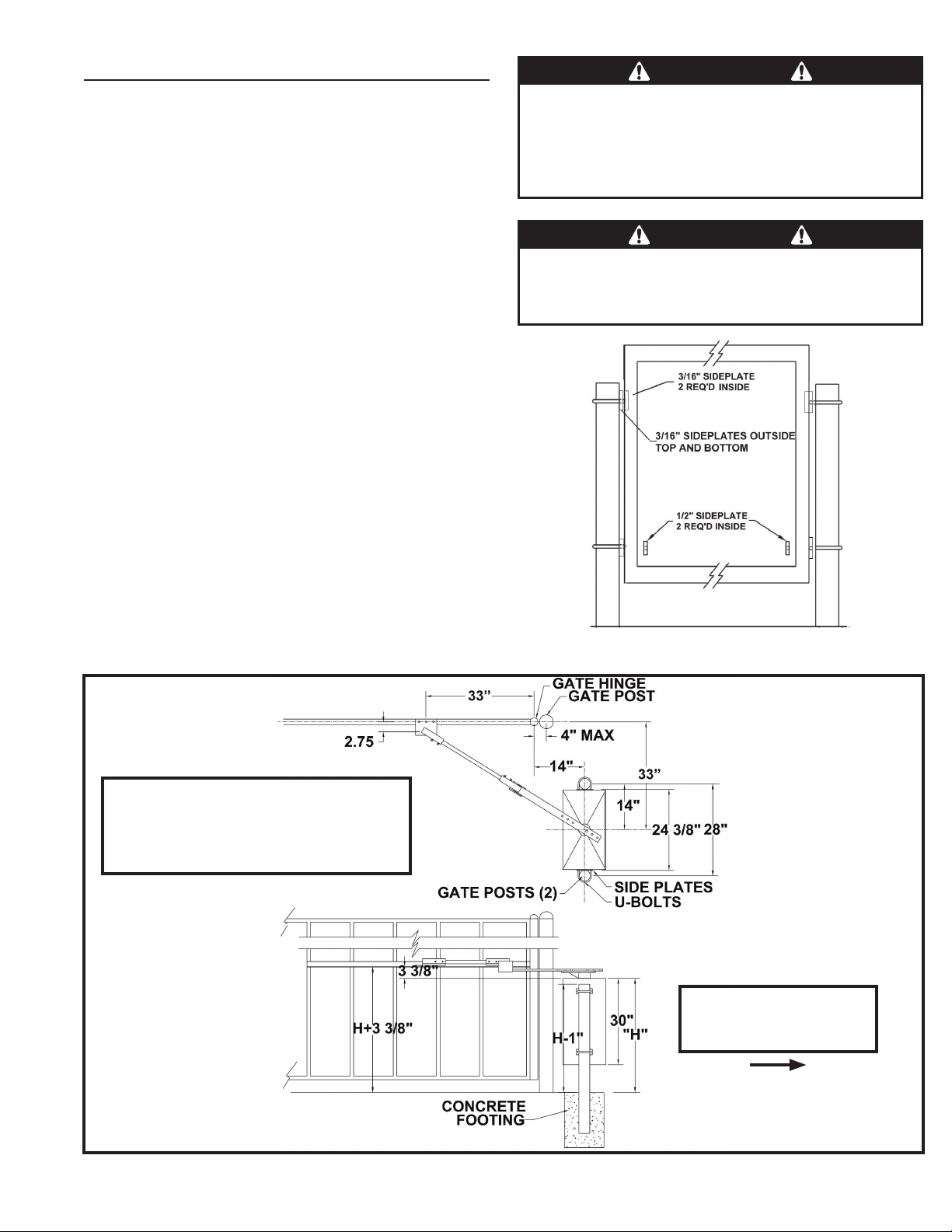
Mounting Pad Installation
The gate operator mounts bolted to posts secured in
concrete footings. The posts support the operator and
prevent it from moving during operation.
Gate Preparation
Before installing the gate operator, make sure the gate’s
swing is free and level throughout the entire swing path. If
the gate does not seem to operate properly, it may affect
the operator performance or greatly shorten the life of the
unit. The gate should be designed so that airfl ow is ample to
prevent wind resistance and drag.
Mounting Specifi cations
Use two 3 - 3-1/2” OD galvanized posts and secure with
concrete footings as shown, length to be determined by
local codes, frost line depth and soil conditions.
Attach the operator with the U-bolts, side plates and hardware
provided. Four 3/16” side plates go on the outside top and
bottom, two 3/16” side plates go on the inside top, and two
1/2” side plates go on the inside bottom (see the illustration
at right). The operator should be positioned at a level to
allow the arm to be installed at mid-height on the gate. “H”
dimension can vary depending on gate construction. Make
sure the posts do not protrude above the operator cabinet.
✓ NOTE: Maximum gate opening angle is approximately 95 degrees,
depending on gate width. If larger opening angle is required,
non-standard positioning of the operator and modifi ed articulating
arms may be required. Contact the factory for technical information,
pricing, and availability.
WARNING
The operator is intended for installation only on gates used for
vehicles. Pedestrians must be supplied with a separate access
opening. The pedestrian access opening shall be designed to
promote pedestrian usage. Locate the gate such that persons
will not come into contact with the vehicular gate during the
entire path of travel of the vehicular gate.
WARNING
The gate must be installed in a location so that enough
clearance is supplied between the gate and adjacent structures
when opening and closing to reduce the risk of entrapment.
Swing gates shall not open into public areas.
Figure 1. Side Plate Installation
23” SPACE REQUIRED BEHIND OPERATOR
FOR ARM CLEARANCE WHILE OPENING
IF NON-STANDARD MOUNTING IS
NECESSARY, CONSULT THE FACTORY
SWG Swing Gate Operator Installation Guide
Figure 2. Mounting Pad Specifi cations
P1227 Revision X5 2-13-2013
- 3 -
OPERATOR ACCESS DOOR
MUST FACE AWAY FROM
DRIVEWAY
Page 6
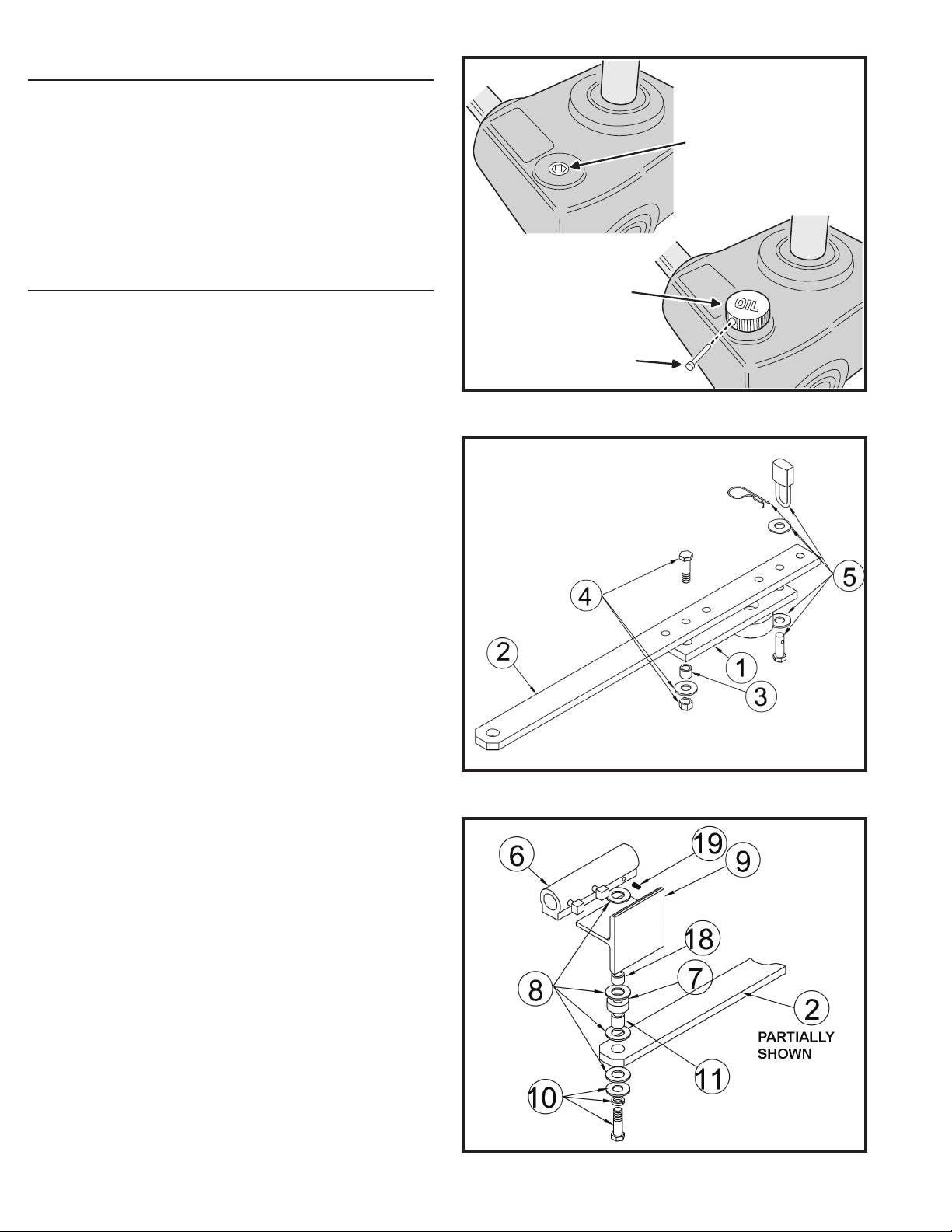
Operator Preparation
Vent Plug Installation
In order to keep gear oil from spilling out during shipping,
gear reducers used in gate operators have either a solid
plug, or a sealed vent plug, installed at the factory.
For operators with a solid plug, replace the solid plug with
the vent plug provided (see Figure 3).
With the vent plug installed, remove the vent plug’s breather
pin to allow the gear box to vent (see Figure 3).
Gate Arm Installation
The gate arm connects the operator to the gate. The arm
supplied can be used in left-hand or right-hand installations.
✓ NOTE: The item numbers shown in these illustrations
are for reference only. For the actual part numbers, refer
to the parts lists in the rear of this manual.
Crank Extension Installation
See Figure 4. Place the crank extension (2) on the operator
crank (1) as shown. Slide a black spacer (3) into the crank
and hold it while sliding a 1/2-13 x 1-3/4” hex head bolt (4)
through the extension and crank. Assemble with a 1/2” fl at
washer and locknut and tighten. Slide the clevis pin (5) and
a 1/2” fl at washer through the crank and the extension. Slide
another 1/2” fl at washer over the end of the pin and lock it
with either a disconnect pull pin or with an optional pad lock
through the pin.
GEAR
REDUCER
REMOVE THE
SOLID PLUG
WITH AN ALLEN
WRENCH
INSTALL THE VENT PLUG
(IF NOT ALREADY INSTALLED)
REMOVE THE
BREATHER PIN
Figure 3. Vent Plug Installation
Overtravel Stop Installation
See Figure 5. Slide a 1/2” lock washer and fl at washer onto
the 1/2-13 x 2 1/2” hex head bolt (10). Add a nylon washer
(8), then slide the bolt through the crank extension (2) and
hold in place Next, insert the yellow-plated pivot spacer
(11) into the crank extension, add a nylon washer (8) and
place the offset spacer (7) on top of the nylon washer. Add
a nylon washer (8) to the top of the offset spacer (7) and
add the silver zinc-fi nish overtravel stop spacer (18). Slide
the overtravel stop bracket (9) over the silver zinc-fi nish
spacer and add the last nylon washer (8) above the bracket.
Carefully screw the bolt assembly into the aluminum gate
clamp (6) until the lock washer has been fully compressed.
The overtravel stop and crank extension should fl oat freely,
without binding, when it is fully assembled. Tighten set
screw (19) to further lock hex bolt (10) in place.
✓ NOTE: Illustrations shown on this page are for right-hand
application. For left-hand, overtravel stop (9) should be
on the opposite side
Figure 4. Crank Extension Installation
SWG Swing Gate Operator Installation Guide
Figure 5. Overtravel Stop Installation
P1227 Revision X5 2-13-2013
- 4 -
Page 7
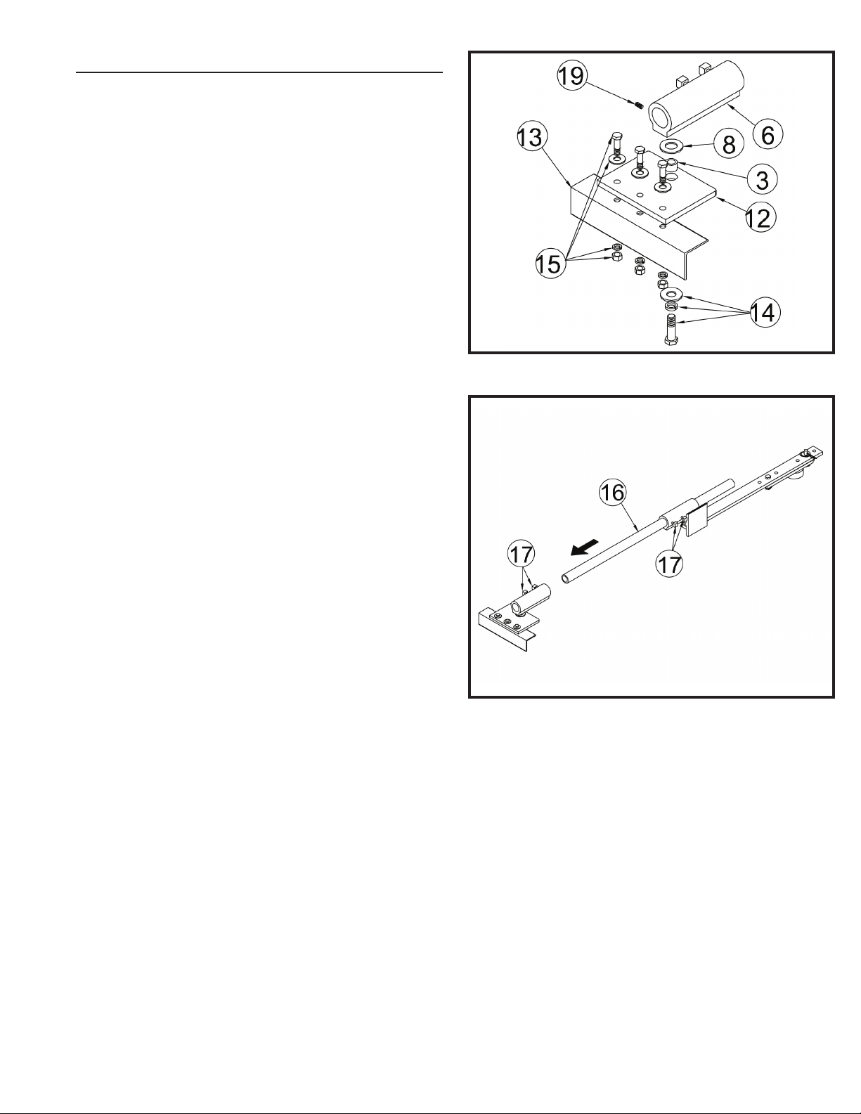
Gate Arm Installation (Cont.)
Gate Plate Installation
See Figure 6. Angle iron (not supplied) (13) should be
welded to the gate prior to this step. Attach the gate plate
(12) to the angle iron using 3/8 bolts, fl at washers, lock
washers and hex nuts (15). Slide a 1/2-13 x 1 1/4” bolt, 1/2”
lock washer, 1/2” fl at washer (14), and a black spacer (3)
through the gate plate. Place a nylon washer (8) over the
opening in the gate plate. Thread the bolt into the hole in the
gate clamp (6) and tighten carefully. Do not overtighten!
Tighten set screw (19) to further lock hex bolt (14) in place.
Choosing Good Harmonics
Good harmonics are necessary to minimize wear and tear
on the operator. The gate will have smoother starts and
stops when the arm is installed with good harmonics. The
gate will have smooth starts and stops when the gate arm
folds over itself when the gate is fully open. Avoid setting up
the gate arm where the crank arm is parallel to the gate leaf
when the gate is open.
Pipe Link Installation
See Figure 7. Slide the pipe link (16) through the arm
assembly as shown. Place the 5/16” square bolts in the gate
clamps (17) and tighten carefully. Do not overtighten!
Figure 6. Gate Plate Installation
Setting the Arm Lengths
Most installations will use the standard dimensions specifi ed.
If non-standard mounting is required, contact the factory for
information.
Figure 7. Pipe Link Installation
SWG Swing Gate Operator Installation Guide
P1227 Revision X5 2-13-2013
- 5 -
Page 8
Operator Setup
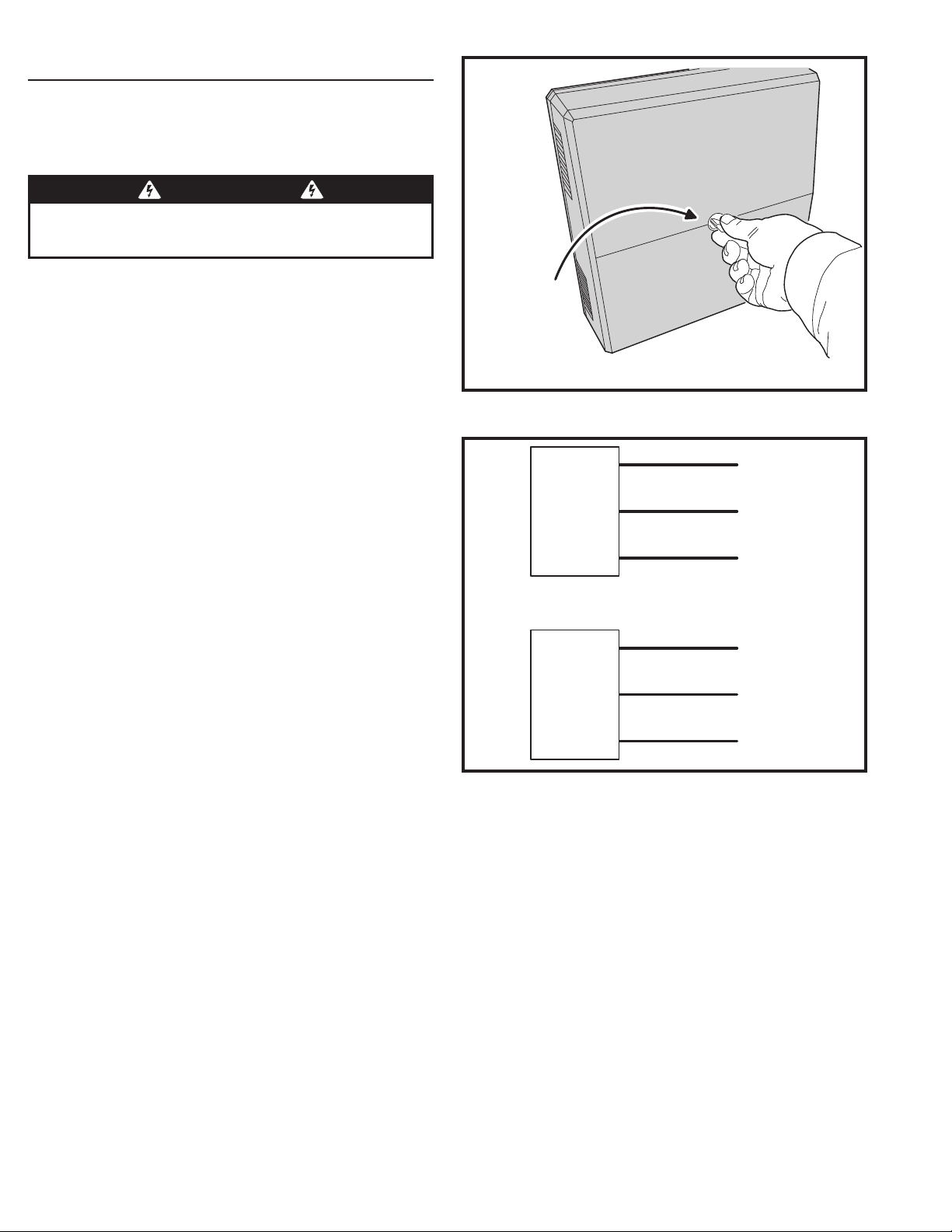
Controller Access
The Controller is protected by a plastic dust cover. To
remove the dust cover, loosen the cover’s wing-screw and
lift the cover off (see Figure 8).
WARNING
ALL AC ELECTRICAL CONNECTIONS TO THE POWER SOURCE AND
THE OPERATOR MUST BE MADE BY A LICENSED ELECTRICIAN AND
MUST OBSERVE ALL NATIONAL AND LOCAL ELECTRICAL CODES
AC Power Connection
All Linear gate operators are supplied with a power
disconnect switch to turn on and off the power available
to the operator. Following wiring specifi cations on Page 2,
incoming power should be brought into the operator and
connected to the labeled pigtails from the disconnect box.
A wiring connections print can also be found on the label
inside the cover of the operator.
Proper thermal protection is supplied with the operator. The
motor contains a thermal overload protector to guard from
overheating the motor due to overload or high-frequency
operation. This overload protector will reset automatically
after the motor cools down.
Earth Ground
Install a ground rod and connect it to the operator’s frame
in every gate operator installation. A good earth ground
is necessary to allow the Controller’s built-in surge and
lightning protection circuitry to work effectively. The physical
bolting of the operator to the mounting posts is not suffi cient
for a good earth ground.
✓ NOTE: Do not splice the ground wire. Use a single piece of solid
copper 12 AWG wire between the ground rod and the operator.
1. Install an 8-foot long copper ground rod next to the operator mounting
pad within three feet of the operator.
2. Use a clamp to connect a solid copper 12 AWG ground wire to the ground rod.
3. Route the ground wire to the operator.
4. Connect the ground wire to the operator’s frame.
LOOSEN KNOB
TO REMOVE
CONTROLLER
COVER
110 VOLT
OPERATOR
POWER
DISCONNECT
220 VOLT
OPERATOR
POWER
DISCONNECT
Figure 9. Power Disconnect Box Wiring
Figure 8. Controller Access
BLACK
WHITE
BOX
BOX
GREEN
BLACK
WHITE
GREEN
HOT
NEUTRAL
GROUND
HOT
HOT
GROUND
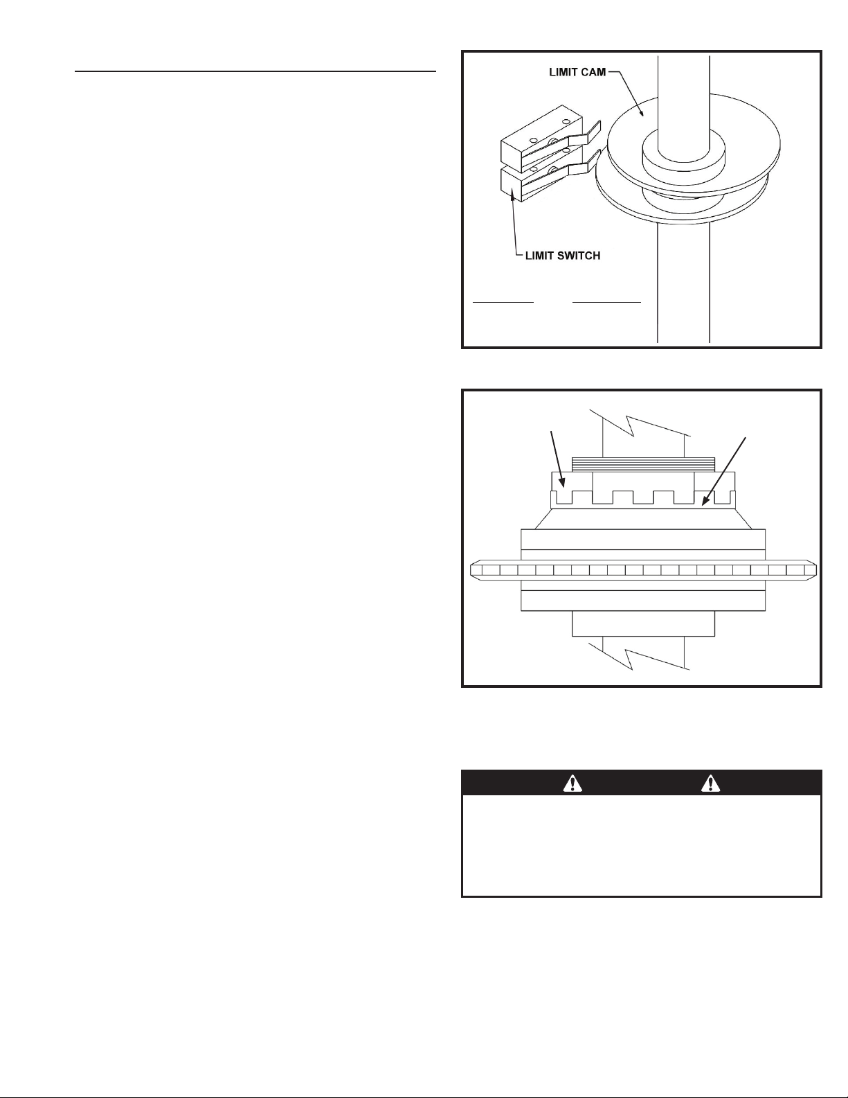
Limit Cam Rough Adjustment
The limit cams are not preset at the factory and must be
adjusted for the length and opening angle of the gate the
operator is installed on. The limit switches are activated
by two rotating limit cams which are attached to the drive
shaft (see Figure 10). The Controller is factory set for right
hand installations. The top cam is for OPEN and the bottom
cam is for CLOSE. The cams fl ip their defi nition in left hand
installations (see left-right hand programming on Page 12).
1. With the gate connected to the gate operator in a mid-travel position,
the power disconnect switch turned OFF, and the torque limiter
set loose enough to slip freely, manually move the gate to its fully
open position.
2. Once the gate is in the fully open position, set the OPEN limit cam so
that it has just triggered the LSO-1 switch.
3. Manually move the gate to its fully closed position, set the CLOSE
limit cam so that it has just triggered the LSC-1 switch.
SWG Swing Gate Operator Installation Guide
- 6 -
P1227 Revision X5 2-13-2013
Page 9
Operator Setup (cont.)
Limit Nuts Rough Adjustment (Cont.)
After fi nishing the initial limit cam adjustments, reposition
the gate to approximately the center of travel. At this time,
adjust the torque limiter as explained below. Turn the power
disconnect switch ON, stand clear of any moving parts
and press the OPEN button. Observe the gate as it runs
through a complete cycle in both directions, and adjust the
limits again if necessary. If the operator stops during travel,
you may need to adjust the open or close current sensor
adjustment or the maximum run timer (see Page 13).
Torque Limiter Adjustment
✓ NOTE: The open and close current sensing may need to be
adjusted before performing the following two steps. See Page 13.
Before adjusting the torque limiter, make sure the gate
is in good working condition. With the gate disconnected
from the gate arm, one person should be able to move the
gate by hand. Be certain the gate moves freely and without
binding throughout its travel.
Torque limiters are set light at the factory. They must be
adjusted during installation, preferably after limit cams have
been manually set. With the gate arm and gate attached,
adjust the torque limiter tight enough to keep it from slipping
during normal operation. The inherent entrapment protection
(current sensing) feature must activate prior to any slipping
of the torque limiter. See Page 13 for current sense setting.
To adjust the torque limiter in model SWG:
1. Bend the locking tabs away from the adjustment nut.
2. Cycle the gate open and closed while observing the torque limiter
action. TURN THE OPERATOR POWER DISCONNECT SWITCH
OFF BEFORE MAKING ANY ADJUSTMENTS.
To increase the torque, turn the adjustment nut clockwise one fl at, or
1/6 turn, at a time until desired output is obtained.
To reduce the torque, turn the adjustment nut counterclockwise one
fl at, or 1/6 turn, at a time until desired output is obtained.
3. When fi nished, bend the locking tabs up to lock the adjustment nut
in place.
WHENEVER HAND
FROM TOP TO BOTTOM:
LEFT HAND RIGHT HAND
LSC-1 LSO-1
LSO-1 LSC-1
OF OPERATION
CHANGES, BOTH
LIMIT CAMS WILL
NEED TO BE
ADJUSTED.
Figure 10. Model SWG Limit Switches & Cams
ADJUSTMENT NUT
Figure 11. Model SWG Torque Limiter
LOCKING TAB
Limit Cam Fine Adjustment
After fi nishing the rough limit cam adjustments and torque
limiter adjustment, reposition the gate to approximately the
center of travel.
1. Turn the power disconnect switch ON.
2. Stand clear of any moving parts and press the OPEN button.
3. After the gate opens, press the CLOSE button.
4. Observe the gate in both directions as it runs through each complete
cycle. Adjust the open or close limit cams again if necessary. If the
gate stops during travel, you may need to adjust the Open or Close
Current Setting or the Maximum Run Timer (see Pages 13-14).
SWG Swing Gate Operator Installation Guide
CAUTION
If the operator is installed in a left-hand installation. Set the
Controller to left-hand operation BEFORE running the operator
for the fi ne setting of the limit cams. Failure to do so will
result in over-shooting the limit switches, and may cause
damage to the operator and/or gate. Refer to programming on
Page 12.
P1227 Revision X5 2-13-2013
- 7 -
Page 10
Controller Features
WHIP
ANTENNA
ANTENNA
CONNECTOR
DISPLAY
PROGRAMMING
INPUT
POWER
TERMINALS
ACCESSORY
TERMINALS
RESET
BUTTON
TERMINALS
PRIMARY/
SECONDARY
COMM LINK
TERMINALS
SINGLE
INPUT
TERMINALS
BUTTONS
POWER
POWER
INDICATORS
OPERATION
BUTTONS
OPERATION AND
PROGRAMMING
INDICATORS
SOLAR
PANEL
TERMINALS
MOTOR
BOARD
COVER
BATTERY
TERMINALS
PLUG-IN
LOOP
DETECTOR
CONNECTORS
FIRE DEPT
INPUT
TERMINALS
OPEN INPUT
TERMINALS
3-BUTTON
STATION
TERMINALS
OPEN AND CLOSE
OBSTRUCTION
INPUT TERMINALS
SWG Swing Gate Operator Installation Guide
REVERSE
INPUT
TERMINALS
OPEN LOOP
INPUT TERMINALS
SHADOW/RESET
REVERSE LOOP
INPUT TERMINALS
SHADOW/RESET LOOP
INPUT TERMINALS
LIMIT SWITCH
INPUT TERMINALS
Figure 12. Controller Features
P1227 Revision X5 2-13-2013
- 8 -
AUXILIARY
RELAY
TERMINALS
ALARM
OUTPUT
TERMINALS
AC MOTOR
OUTPUT
TERMINALS
Page 11
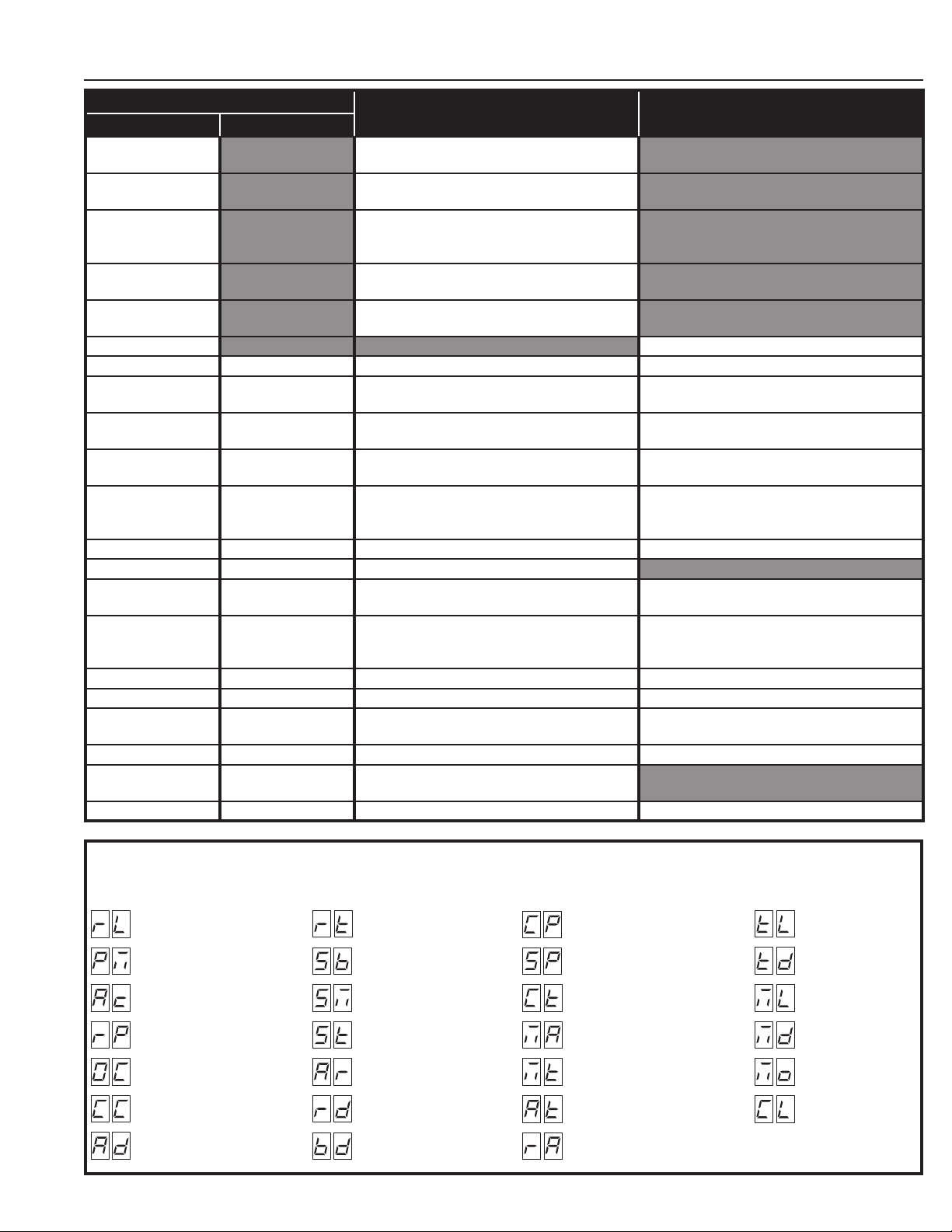
Indicator Descriptions
INDICATOR DEFINITION
OPERATION PROGRAMMING
24 VOLT INPUT
POWER
24 VOLT DC
ACCY POWER
LOW VOLTAGE AC POWER IS PRESENT
LOW VOLTAGE DC POWER IS PRESENT
INDICATION WHEN LIT
DURING NORMAL OPERATION
INDICATION WHEN LIT
DURING PROGRAMMING
OPEN SIGNAL PRESENT FROM THE INTERNAL
OPEN
RECEIVER OR AN EXTERNAL DEVICE
CONNECTED TO THE OPEN INPUT TERMINAL
CLOSE
STOP
CLOSE SIGNAL IS PRESENT FROM A DEVICE
CONNECTED TO THE CLOSE INPUT TERMINAL
STOP INPUT TERMINAL IS OPEN AND
NOT CONNECTED TO COMMON
PROGRAM CONTROLLER IS IN PROGRAMMING MODE
REVERSE DELAY SET SIGNAL FROM REVERSING DEVICE IS PRESENT SET REVERSE DELAY TIME
LOCKOUT ALARM SET
RADIO LEARN
OPEN CURRENT SET
CONTROLS AND OPERATOR ARE LOCKED OUT
BECAUSE OF EXISTING TROUBLE CONDITION
BUILT-IN RECEIVER IS DETECTING A RADIO
SIGNAL FROM A REMOTE CONTROL
MOTOR CURRENT HAS EXCEEDED THE
OPEN CURRENT SETTING WHILE OPENING
SET RUN ALARM AND PRE-START ALARM
TRANSMITTERS CAN BE ENTERED INTO
MEMORY (UP TO 40 TRANSMITTERS)
SET MAXIMUM OPEN CURRENT
OPEN OBSTRUCTION TERMINAL CONNECTED
OPEN OBSTR MGT 2 SET
TO COMMON BY BEAM OR SAFETY EDGE, OR
SET MGT #2 FUNCTION
SIGNAL FROM MGT OBSTACLE TRANSMITTER
OPEN RELAY LH/RH SET OPEN RELAY IS ACTIVATED SET LEFT-HAND RIGHT-HAND OPERATION
OPEN LIMIT BRAKE DELAY OPEN LIMIT SWITCH IS ACTIVATED
CLOSE CURRENT SET
MOTOR CURRENT HAS EXCEEDED THE
CLOSE CURRENT SETTING WHILE CLOSING
SET MAXIMUM CLOSE CURRENT
CLOSE OBSTRUCTION TERMINAL CONNECTED
CLOSE OBSTR MGT 1 SET
TO COMMON BY BEAM OR SAFETY EDGE, OR
SET MGT #1 FUNCTION
SIGNAL FROM MGT OBSTACLE TRANSMITTER
CLOSE RELAY AUTO CLOSE SET CLOSE RELAY IS ACTIVATED SET AUTO-CLOSE TIME
CLOSE LIMIT AC DC SET CLOSE LIMIT SWITCH IS ACTIVATED SET MOTOR TYPE
SINGLE SET
SINGLE TERMINAL CONNECTED TO COMMON
BY AN EXTERNAL PUSHBUTTON OR RADIO
SET SINGLE BUTTON INPUT FUNCTION
MAX RUN SET MAXIMUM RUN TIMER HAS BEEN EXCEEDED SET MAXIMUM RUN TIME
COMM LINK SET
DUAL OPERATOR CONNECTION DETECTED,
BLINKS IF CONNECTION HAS FAILED
MAINT ALERT SET MAINTENANCE IS REQUIRED ON OPERATOR SET MAINTENANCE ALERT CYCLE COUNT
LEFT OR RIGHT
"RL"
HAND OPERATION
SINGLE OR
"PM"
DUAL GATE
AUTO CLOSE
"AC"
TIMER
RUN ALARM
"RP"
PRE-START ALARM
MAXIMUM OPEN
"OC"
CURRENT
MAXIMUM CLOSE
"CC"
CURRENT
ADVANCED
"AD"
PROGRAMMING
SWG Swing Gate Operator Installation Guide
APEX FUNCTION DISPLAY INDICATIONS
"RT"
"SB"
"SM"
"ST"
"AR"
"RD"
"BD"
MAXIMUM
RUN TIMER
SINGLE BUTTON
INPUT SETUP
STAGGER
MODE
STAGGER
TIME
AUXILIARY
RELAY MODE
REVERSE
DELAY TIME
BRAKE
DELAY TIME
P1227 Revision X5 2-13-2013
- 9 -
"CP"
"SP"
"CT"
"MA"
"MT"
"AT"
"RA"
CONSTANT
PRESSURE MODE
SHADOW LOOP
OPEN INHIBIT
RESET CYCLE
COUNT
MAINTENANCE ALERT
TRIGGER
MID-TRAVEL
STOP POSITION
ANTI-TAILGATE
ENABLE
RADIO
ENABLE
"TL"
"TD"
"ML"
"MD"
"MO"
"CL"
LEARN
TRANSMITTERS
DELETE
TRANSMITTERS
LEARN MGT
TRANSMITTERS
ERASE MGT
TRANSMITTERS
MOTOR TYPE
SELECTION
RESET TO
FACTORY DEFAULTS
Page 12

Terminal Descriptions
TERMINAL GROUP FUNCTION
AC N
AC
DC DC +
RESET
COMMON
C
A
COMMON
SINGLE
COMMON
FIRE DEPT
COMMON
OPEN
OPEN
CLOSE
COMMON
STOP
24 VOLT INPUT
ACCESSORY POWER PROVIDES 24 VOLT DC POWER FOR ACCESSORIES. (.5A MAX)
RESET BUTTON FACTORY CONNECTED TO THE CONTROLLER’S RESET BUTTON.
COMM LINK FOR 3-WIRE NETWORK CONNECTION TO SECOND OPERATOR IN DUAL GATE INSTALLATIONS.B
SINGLE BUTTON INPUT
FIRE BOX INPUT CONNECT TO NORMALLY OPEN SWITCH IN FIRE BOX FOR FIRE DEPARTMENT ACCESS.
OPEN INPUT
3-BUTTON
STATION INPUT
FACTORY CONNECTED TO 24 VAC FROM TRANSFORMER OR
24 VDC FROM CONTINUOUS DUTY DC SUPPLY.
CONNECT TO NORMALLY OPEN SWITCH FOR SINGLE BUTTON OPERATION. ALTERNATES
BETWEEN OPEN-CLOSE OR OPEN-STOP-CLOSE DEPENDING ON PROGRAMMING.
CONNECT TO NORMALLY OPEN DEVICES (KEYPAD, CARD READER, KEYSWITCH,
TELEPHONE ENTRY SYSTEM) TO OPEN THE GATE. A CONSTANT OPEN INPUT WILL
OVERRIDE THE MID-TRAVEL STOP AND HALT THE AUTO CLOSE TIMER UNTIL RELEASED.
CONNECT TO 3-BUTTON STATION FOR OPEN-CLOSE-STOP CONTROL. A CONSTANT OPEN INPUT
WILL OVERRIDE THE MID-TRAVEL STOP AND HALT THE AUTO CLOSE TIMER UNTIL RELEASED.
COM
OPEN
OBSTRUCTION
INPUT
O-OBS
C-OBS
CLOSE
OBSTRUCTION
INPUT
COM
COM
REV
OPEN LOOP
OPEN LOOP
REVERSE LOOP
REVERSE LOOP
SHADOW/RESET LOOP
SHADOW/RESET LOOP
+
N.O.
COM
N.C.
+
+
-
SWG Swing Gate Operator Installation Guide
REVERSE
OPEN LOOP
REVERSE LOOP
SHADOW/RESET LOOP
ALARM FACTORY CONNECTED TO THE ALARM BEEPER.
AUX RELAY
24 VOLT SOLAR PANEL NOT USED WITH THIS MODEL OPERATOR.
24 VOLT BATTERY NOT USED WITH THIS MODEL OPERATOR.
CONNECT TO NORMALLY OPEN DEVICES (GATE EDGE, PHOTO BEAM) TO DETECT AN
OBSTRUCTION DURING OPENING. WHILE GATE IS MOVING, ANY OPEN OBSTRUCTION
SIGNAL WILL CAUSE THE GATE TO STOP, REVERSE A SHORT DISTANCE, AND THEN STOP
AGAIN. AT THIS TIME THE AUTO CLOSE TIMER IS DISABLED, AND A RENEWED INPUT
WILL BE REQUIRED TO START THE GATE AGAIN. SHOULD THE GATE BE RESTARTED
AND THE OBSTACLE SIGNAL OCCUR AGAIN PRIOR TO REACHING A LIMIT, THE GATE
WILL STOP AGAIN, LOCKOUT, AND SOUND THE CONTINUOUS TONE ALARM.
CONNECT TO NORMALLY OPEN DEVICES (GATE EDGE, PHOTO BEAM) TO DETECT AN
OBSTRUCTION DURING CLOSING. WHILE GATE IS MOVING, ANY CLOSE OBSTRUCTION
SIGNAL WILL CAUSE THE GATE TO STOP, THEN REVERSE AND TRAVEL TO THE FULL
OPEN POSITION. SHOULD A OPEN OBSTRUCTION INPUT OR AN OPEN DIRECTION
INHERENT ENTRAPMENT CONDITION OCCUR PRIOR TO THE GATE REACHING THE
OPEN LIMIT, THE OPERATOR WILL LOCKOUT AND SOUND THE CONTINUOUS TONE
ALARM. IF THE AUTO CLOSE TIMER IS SET, WHEN THE CLOSE OBSTRUCTION INPUT
IS CLEARED, THE GATE WILL CLOSE WHEN THE AUTO CLOSE TIMER EXPIRES.
CONNECT TO NORMALLY OPEN DEVICES TO CAUSE A REVERSAL WHEN THE GATE IS
TRAVELING CLOSED. THE GATE WILL REVERSE TO THE FULL OPEN POSITION.
CONNECT TO OPEN LOOP/FREE EXIT LOOP. THE GATE WILL OPEN
WHEN THE LOOP IS TRIGGERED, AND REMAIN OPEN AS LONG AS
THE LOOP IS TRIGGERED. REQUIRES LOOP DETECTOR.
CONNECT TO REVERSE LOOP. TRIGGERING THE LOOP WILL CAUSE A
REVERSAL WHEN THE GATE IS TRAVELING CLOSED. THE GATE WILL REVERSE
TO THE FULL OPEN POSITION. REQUIRES LOOP DETECTOR.
CONNECT TO SHADOW/RESET LOOP TO KEEP THE GATE IN ITS FULLY OPEN
POSITION AS LONG AS THE SIGNAL IS PRESENT. USED TO KEEP GATE OPEN
WHILE VEHICLE IS PASSING THROUGH. REQUIRES LOOP DETECTOR.
FOR CONNECTION TO AUXILIARY DEVICES (MAGNETIC LOCK, SOLENOID LOCK,
STROBE LIGHT) FOR ACTIVATION (OR DEACTIVATION) DURING GATE OPERATION.
P1227 Revision X5 2-13-2013
- 10 -
Page 13

Operator Accessory Connections
3-BUTTON STATION
KEYSWITCH
FIRE ACCESS SWITCH
TELEPHONE ENTRY
KEYPAD
SOLENOID LOCK
EXTERNAL POWER
PHOTOEYE FOR REVERSE
PHOTOEYE FOR CLOSE OBSTRUCTION
PHOTOEYE FOR OPEN OBSTRUCTION
SINGLE-CHANNEL RADIO RECEIVER
TWO-CHANNEL RADIO RECEIVER
CHANNEL #1
OPEN/CLOSE
MAGLOCK
GATE EDGE SENSOR FOR REVERSE
WARNING STROBE OR AUDIBLE SOUNDER
WIRELESS GATE EDGE SENSOR
MGT
TRANSMITTER
SWG Swing Gate Operator Installation Guide
Figure 13. Operator Accessory Connections
- 11 -
P1227 Revision X5 2-13-2013
Page 14

Basic Controller Programming
Programming Overview
The Controller can be programmed with various options for the operator.
The programming fi elds are defi ned as “functions” that have “options”.
To make setup easier for the installer, the Controller’s programming is
divided into two groups: basic and advanced. The basic programming
group contains the functions commonly used in most swing gate
installations. The advanced programming group contains functions less
commonly used (i.e. dual gate stagger delay, maximum run timer, etc.).
Entering Programming Mode
Enter programming mode by pressing the UP and DOWN buttons
together for one second. While in programming mode the PROGRAM
indicator will light.
Exiting Programming Mode
Exit programming mode at any time by pressing the UP and DOWN
buttons together. The Controller will automatically exit programming
mode after three minutes of inactivity.
Programming Keystrokes
(Typical Programming Method)
While in programming mode, press the UP or DOWN buttons to scroll
through the programming functions. When the desired function is
displayed press the ENTER button to display the currently set option for
the function. When an option is displayed, the decimal points are lit.
To change the option, press and hold the ENTER button for 1 second. To
indicate that an option is ready to be changed, the display will fl ash. While
the display is fl ashing, press the UP or DOWN button to display the other
options available for that function.
When the desired option is displayed, press the ENTER button to store
it into memory. To select another function, press ENTER, UP, or DOWN.
Left or Right Hand Operation
The factory default is for right hand operation (operator on right side of
the driveway when viewed from the inside of the gate). For left hand
installations, program the Controller for left hand operation.
Dual Gate Enable
The factory default is for single gate operation. For dual gate operation,
wire the two gate controllers together through the COMM LINK terminals
(see Page 21) and enable dual gate operation with this programming
step.
✓ NOTE: The Mid-travel Stop feature is disabled when dual gate
operation is enabled for paired units.
Auto Close Timer
The factory default turns off the Auto Close Timer. The timer can be set
from 1 to 59 seconds and from 1 to 9 minutes. When the Auto Close
Timer is set, after opening, the gate will wait for the length of the Auto
Close Timer then close automatically.
DOWN UP
PRESS DOWN AND UP
BUTTONS TOGETHER
FOR ONE SECOND
ENTERING
PROGRAMMING
SELECT
FUNCTION
UP
OR
DOWN
PRESS UP OR DOWN
TO SCROLL DISPLAY
THROUGH FUNCTIONS
ENTER
PROGRAMMING
KEYSTROKES
FUNCTION
"RL"
LEFT HAND
RIGHT HAND
FUNCTION
"PM"
SINGLE GATE
DUAL GATE
FUNCTION
"AC"
PRESS UP OR
DOWN TO CYCLE
THROUGH OPTIONS
PRESS ENTER TO
SELECT AN OPTION
PROGRAM
INDICATOR
AND
PROGRAM INDICATOR
WILL LIGHT WHEN SYSTEM
IS IN PROGRAM MODE
CURRENTLY
SET OPTION
PRESS ENTER TO
DISPLAY CURRENTLY
OPTION READY
TO CHANGE
ENTER ENTER ENTER
PRESS ENTER FOR
ONE SECOND TO
SELECT OPTION
(THE DISPLAY
WILL FLASH)
SET OPTION
DOWN TO CYCLE
THROUGH OPTIONS
PRESS ENTER TO
SELECT AN OPTION
DOWN TO CYCLE
THROUGH OPTIONS
PRESS ENTER TO
SELECT AN OPTION
TO CHANGE
OPTIONS
PRESS UP OR
OPTIONS
PRESS UP OR
OPTIONS
CHOOSE
OPTION
UP
OR
DOWN
PRESS ENTER
PRESS UP
OR DOWN
OPTION
RIGHT HAND INSTALLATION
(OPERATOR ON RIGHT OF GATE
WHEN VIEWED FROM INSIDE)
LEFT HAND INSTALLATION
(OPERATOR ON LEFT OF GATE
WHEN VIEWED FROM INSIDE)
SINGLE GATE INSTALLATION
DUAL GATE INSTALLATION
AUTO CLOSE TIMER DISABLED
SET TIMER VALUE
1 TO 59 SECONDS
SET TIMER VALUE
1 TO 9 MINUTES
TO STORE
OPTION
PRESS UP, DOWN
OR ENTER SELECT
NEXT FUNCTION
OPTION
STORED
OR
UP
OR
DOWN
SELECT
FUNCTION
SWG Swing Gate Operator Installation Guide
AUTO CLOSE
TIMER
P1227 Revision X5 2-13-2013
- 12 -
Page 15

Basic Controller Programming (Cont.)
Run Alarm and Pre-start Alarm
The factory default is Run Alarm on and a 3-second Pre-start Alarm. The
operator’s beeper will sound 3 seconds before the operator starts. The
options are:
• Run Alarm Off and Pre-start Alarm Off
• Run Alarm On and Pre-start Alarm Off
• Run Alarm On and Pre-start Alarm On for 1-9 Seconds
Maximum Open Direction Current Setting
To detect obstacles or mechanical problems with the gate, the operator
monitors its motor current. If the open current load exceeds the
programmed maximum load range number, the operator will stop, reverse
a short distance, then stop again. The Auto Close Timer will be disabled,
and another open request will be required to start the operator again. If
after restart, the overload or an open obstacle happens again before the
open limit is reached, the operator will lockout and sound the alarm.
To measure the motor load used during opening, while this function is
being displayed, push and hold the OPEN button to fully open the gate.
During movement, the motor current will be displayed as a load number
from 0 to 99. This number is useful for troubleshooting but not for setting
the motor current. At the end of travel, a different number will fl ash. This
number indicates the range above and below the average motor current
during the run. Using the + and - buttons, set the programmed range
number so that a minimal force (50-75 lbs.) will activate a reversal should
an obstruction occur, but high enough to keep the gate moving under
normal conditions without interruption.
FUNCTION
"RP"
PRESS UP OR
DOWN TO CYCLE
THROUGH OPTIONS
PRESS ENTER TO
SELECT AN OPTION
RUN ALARM
PRE-START ALARM
FUNCTION
"OC"
MAX OPEN
CURRENT
FUNCTION
"CC"
OPTIONS
RUN ALARM OFF
PRE-START ALARM OFF
RUN ALARM ON
PRE-START ALARM OFF
RUN ALARM ON
PRE-START ALARM ON FOR 1 - 9 SECONDS
OPTIONS
PRESS AND HOLD THE OPEN BUTTON
UNTIL THE OPERATOR RUNS FULLY OPEN
SUGGESTED MINIMUM NUMBER WILL
FLASH, ADJUST TO THE PROPER FORCE
PRESS ENTER TO STORE THE FORCE
ENTER
OPTIONS
PRESS AND HOLD THE CLOSE BUTTON
UNTIL THE OPERATOR RUNS FULLY CLOSED
Maximum Close Direction Current Setting
To detect obstacles or mechanical problems with the gate, the
operator monitors its motor current. If the close current load exceeds
the programmed maximum load range number, the operator will stop,
reverse, and travel to the full open position. Should a open obstruction
input or an open direction inherent entrapment condition occur prior to
the gate reaching the open limit, the operator will lockout and sound the
continuous tone alarm. Another close request will be required to start the
operator again. If after restart, the overload or a close obstacle happens
again before the close limit is reached, the operator will lockout and
sound the alarm. If the auto close timer is set, when the close obstruction
input is cleared, the gate will close when the auto close timer expires.
To measure the motor load used during closing, while this function is
being displayed, push and hold the CLOSE button to close the gate.
During movement, the motor current will be displayed as a load number
from 0 to 99. This number is useful for troubleshooting but not used for
setting the motor current. At the end of travel, a different number will fl ash.
This number indicates the range above and below the average motor
current during the run. Using the + and - buttons, set the programmed
range number so that a minimal force (50-75 lbs.) will activate a reversal
should an obstruction occur, but high enough to keep the gate moving
under normal conditions without interruption.
MAX CLOSE
CURRENT
SUGGESTED MINIMUM NUMBER WILL
FLASH, ADJUST TO THE PROPER FORCE
PRESS ENTER TO STORE THE FORCE
ENTER
SWG Swing Gate Operator Installation Guide
- 13 -
P1227 Revision X5 2-13-2013
Page 16

Advanced Controller Programming
Entering Advanced Programming Mode
To access and program the Advanced Programming functions, for each
programming session, Advanced Programming must be enabled.
After exiting programming, the Advanced Programming functions
will be available on the programming display during the next
programming session unless the operator has run 50 or more
cycles. After that, Advanced Programming must be enabled again.
Maximum Run Time
The factory default for the Maximum Run Time (MRT) is 99 seconds.
When the operator starts, a timer will begin counting. If a open or close
limit is not reached or an obstacle or reversing input is not received
before the timer expires, the operator will stop, the unit locks out and the
alarm sounds. The timer can be set for 10 to 99 seconds, but should be
left at 99 in most applications. Setting it too close to the actual run time
may cause the time to expire with changing ambient temperature, gate
conditions, etc…
If AC is present and an open or close limit is not reached or an obstacle
or reversing input is not received before this timer exceeds MRT, the
operator will stop, the unit locks out and the alarm sounds.
Single Button Input Setup
This function is used for selecting the operation for single button controls
and radio receivers.
The factory default sets the SINGLE input terminal so successive inputs
will cycle the operator in OPEN-STOP-CLOSE-STOP order.
Alternately, the SINGLE input can be set to cause the gate to OPEN
unless the gate is fully open. If the gate is fully open, the input will cause
the gate to CLOSE.
Stagger Mode
This function is used in dual gate installations only. The factory
default sets the Stagger Mode to OFF. In dual gate installations the
two operators communicate through the 3-wire COMM LINK interface.
When using the Stagger Mode, set one operator for delayed opening and
the other operator for delayed closing. The Stagger Time programming
function (see below) sets the length of the delay.
✓ NOTE: This function will only be displayed if dual gate operation is
selected.
Stagger Delay Time
This function is used in dual gate installations only. The factory
default sets the Stagger Time to 0 seconds (OFF). The Stagger Time
sets the delay for the Stagger Mode. The Stagger Delay Time can be set
from 1-99 seconds.
✓ NOTE: This function will only be displayed if dual gate operation is
selected.
FUNCTION
"AD"
ADVANCED
PROGRAMMING
FUNCTION
"RT"
MAXIMUM RUN
TIMER
FUNCTION
"SB"
SINGLE BUTTON
INPUT SETUP
FUNCTION
"SM"
PRESS UP OR
DOWN TO CYCLE
THROUGH OPTIONS
PRESS ENTER TO
SELECT AN OPTION
STAGGER
MODE
FUNCTION
"ST"
OPTIONS
ADVANCED PROGRAMMING FUNCTIONS
WILL NOT BE DISPLAYED
ADVANCED PROGRAMMING OPTIONS
WILL BE DISPLAYED
PRESS UP OR
DOWN TO CYCLE
THROUGH OPTIONS
PRESS ENTER TO
SELECT AN OPTION
OPTIONS
ENTER
ENTER
OPTIONS
SINGLE INPUT WILL CYCLE OPERATOR
IN ORDER OF OPEN-STOP-CLOSE-STOP
SINGLE INPUT WILL OPEN OPERATOR,
IF OPERATOR IS ALREADY OPEN, SINGLE
INPUT WILL CLOSE OPERATOR
PRESS UP OR
DOWN TO CYCLE
THROUGH OPTIONS
PRESS ENTER TO
SELECT AN OPTION
OPTIONS
DISABLES STAGGER FUNCTION
SETS THIS OPERATOR FOR
DELAYED OPEN
SETS THIS OPERATOR FOR
DELAYED CLOSE
OPTIONS
STAGGER TIMER DISABLED
NOTE: ADVANCED PROGRAMMING
WILL STAY ENABLED AFTER
EXITING PROGRAMMING UNTIL
THE GATE CYCLES 50 TIMES
DISPLAY SHOWS CURRENT
MAXIMUM RUN TIME SETTING
PRESS ENTER FOR 1 SECOND
WHILE DISPLAY IS FLASHING, PRESS
UP OR DOWN TO CHANGE THE
MAXIMUM RUN TIME (10-99 SECONDS)
PRESS ENTER TO STORE THE VALUE
DUAL GATES
ONLY
SWG Swing Gate Operator Installation Guide
SET STAGGER DELAY VALUE
1 TO 99 SECONDS
PRESS UP OR
DOWN TO CYCLE
THROUGH OPTIONS
STAGGER
DELAY TIME
P1227 Revision X5 2-13-2013
- 14 -
PRESS ENTER TO
SELECT AN OPTION
DUAL GATES
ONLY
Page 17

Advanced Controller Programming (Cont.)
Auxiliary Relay Mode
The Auxiliary Relay has normally open and normally closed contacts.
The factory setting disables the Auxiliary Relay. The relay can be set for:
• Maglock: To deactivate a magnetic or solenoid gate lock, the relay
will energize during any pending or actual gate motion (open only).
• M4: To deactivate a magnetic or solenoid gate lock, the relay will
energize during any pending or actual gate motion (open only).
3 seconds after the gate starts to move, the relay will de-energize.
This option is used for higher current solenoid locks.
• Ticket Dispenser: The relay will energize while the gate is moving
in the open direction and at the full open limit, or in an entrapment
condition.
• Strobe: To activate a warning strobe light, the relay will energize
during any pending or actual gate motion (either open or close).
• Alarm: The relay will energize if the gate is manually forced open
from the full closed position.
Reverse Delay Time
The factory default sets the Reverse Delay to 1 second. The operator
will wait the length of the delay before reversing direction. This feature
will not change the reversal time when the operator is responding to an
entrapment condition from an obstruction input or inherent entrapment
protection sensor. The Reverse Delay can be set from 1 to 9 seconds.
Heaver gates require a longer delay to allow time for the gate to stop.
Brake Delay Time
This function is displayed, but only used in operators with
mechanical brakes. The Model SWG does not have a mechanical
brake.
The factory default sets the Brake Delay to no delay (0 seconds). Heavy
gates may require delayed braking to allow the gate to slow down before
stopping it. The operator can be set to wait the length of the delay after
running before applying the brake. The Brake Delay can be set from
0 to 3 seconds.
Constant Pressure Mode
The factory default allows momentary pressure on a control station’s
OPEN or CLOSE button to cycle the operator. The controller can be set
to require constant pressure on the OPEN, CLOSE, or both buttons to
run the operator.
✓ NOTE: If a button is set for constant pressure, and it is released
before the operator reaches the open or close limit, the operator will
stop the gate at its current position.
Shadow Loop Open Prevention
If the shadow loop is triggered, it always prevents the gate from closing if
the Auto Close Timer activates or a CLOSE command is given while the
gate is at the full open position.
The controller can also be set to prevent the gate from opening if the
shadow loop is triggered while the gate is at the close limit position. This
prevents a swing gate from opening into a vehicle if it’s parked near the
gate on the inside.
FUNCTION
"AR"
PRESS UP OR
DOWN TO CYCLE
THROUGH OPTIONS
PRESS ENTER TO
SELECT AN OPTION
AUXILIARY
RELAY MODE
FUNCTION
"RD"
REVERSE
DELAY TIME
FUNCTION
"BD"
BRAKE
DELAY TIME
FUNCTION
"CP"
PRESS UP OR
DOWN TO CYCLE
THROUGH OPTIONS
PRESS ENTER TO
SELECT AN OPTION
CONSTANT
PRESSURE MODE
FUNCTION
"SP"
OPTIONS
OPTIONS
PRESS UP OR
DOWN TO CYCLE
THROUGH OPTIONS
PRESS ENTER TO
SELECT AN OPTION
OPTIONS
PRESS UP OR
DOWN TO CYCLE
THROUGH OPTIONS
PRESS ENTER TO
SELECT AN OPTION
OPTIONS
OPTIONS
AUXILIARY RELAY DISABLED
AUXILIARY RELAY USED FOR
MAGLOCK CONTROL
AUXILIARY RELAY USED FOR
MAGLOCK OR SOLENOID CONTROL
3 SECOND DELAY TO RE-ENERGIZE
AUXILIARY RELAY USED FOR
TICKET DISPENSER CONTROL
AUXILIARY RELAY USED FOR
WARNING STROBE LIGHT
AUXILIARY RELAY USED FOR
CONNECTION TO ALARM DEVICE
SET TIMER VALUE
1 TO 9 SECONDS
SET TIMER VALUE
0 TO 3 SECONDS
CONSTANT PRESSURE SET TO OFF
(MOMENTARY PRESSURE ON)
OPEN BUTTON SET FOR
CONSTANT PRESSURE
CLOSE BUTTON SET FOR
CONSTANT PRESSURE
OPEN AND CLOSE BUTTONS BOTH SET
FOR CONSTANT PRESSURE
STANDARD OPERATION
SHADOW LOOP INHIBITS CLOSING ONLY
OPEN INHIBIT ON, SHADOW LOOP INHIBITS
OPENING AND CLOSING
SWG Swing Gate Operator Installation Guide
- 15 -
PRESS UP OR
DOWN TO CYCLE
THROUGH OPTIONS
SHADOW LOOP
OPEN PREVENTION
P1227 Revision X5 2-13-2013
PRESS ENTER TO
SELECT AN OPTION
Page 18

Advanced Controller Programming (Cont.)
Reset Cycle Count
The Controller counts of the number of times the operator has been
cycled full open and close. The cycle count can be displayed. The display
will scroll the cycle count number, fl ashing two digits at a time from left
to right.
To reset the Cycle Count, press and hold the ENTER button for 2 seconds
while the Cycle Count is displayed.
If the Maintenance Alert has been triggered, resetting the Cycle Count
will also reset the Maintenance Alert indicator.
Maintenance Alert Trigger
The Controller has a MAINT ALERT indicator that can be programmed
to light when the number of activations exceeds a set number of cycles.
The factory default sets the Maintenance Alert Trigger to 10,000 cycles.
The Maintenance Alert Trigger can be programmed for 5, 10, 15, or 25
thousand cycles.
The Maintenance Cycle Count can be reset independently from the
operator’s absolute Cycle Count.
Mid-travel Stop Position
The Controller can be programmed so the gate will stop at a mid-travel
point instead of fully opening. This can be useful in installations where a
large gate, that takes a long time to open and close fully, only needs to
be opened partway to allow traffi c to pass.
The factory default sets the Controller for full open operation. Alternately,
the Controller can be programmed to open for 1 to 99 seconds then stop,
before reaching the open limit.
When a Mid-travel Stop Position time has been programmed, the gate
will still fully open if the Fire Department input is triggered, if the OPEN
button is held down beyond the Mid-travel Stop Position, or a close
obstruction or reverse loop input is triggered.
✓ NOTE: The Mid-travel Stop feature is disabled when dual gate
operation is enabled for paired units.
Anti-tailgate Enable
The factory default sets the Anti-tailgate Enable to OFF. With this setting,
during a gate cycle, after the shadow loop has been triggered by the
vehicle and then has cleared after the vehicle passes, the Auto Close
Timer or a CLOSE command is required to begin closing the gate.
If the Anti-tailgate Enable is set to ON, the gate will close immediately
as soon as the shadow loop has cleared. Any subsequent shadow loop
triggers while the gate is closing will stop the gate. When the shadow loop
clears, the gate will continue closing.
Radio Enable
The Controller contains a built-in MegaCode® radio receiver to allow
activation from up to 40 access control transmitters and two Model MGT
(gate edge) transmitters. The factory default enables the internal radio
receiver. Alternately, the internal receiver can be disabled.
Antenna Installation
The Controller is supplied with a local whip antenna installed. If using a
remote antenna, remove the whip antenna and connect coax cable from
the antenna to the ANTENNA connector.
SWG Swing Gate Operator Installation Guide
- 16 -
FUNCTION
"CT"
RESET CYCLE
COUNT
FUNCTION
"MA"
PRESS UP OR
DOWN TO CYCLE
THROUGH OPTIONS
PRESS ENTER TO
SELECT AN OPTION
PRESS ENTER TO START THE CYCLE COUNT DISPLAY
1ST DISPLAY
NOTE: PRESS ENTER FOR 2 SECONDS
WHILE THE "CT" FUNCTION IS DISPLAYED
TO RESET THE CYCLE COUNT TO ZERO
2ND DISPLAY 3RD DISPLAY 4TH DISPLAY
EXAMPLE ABOVE SHOWS 10,420 CYCLES
DECIMAL POINT LIT
ON 4TH DISPLAY
OPTIONS
DISABLES THE MAINTENANCE ALERT
FUNCTION
SETS THIS MAINTENANCE ALERT TRIGGER
FOR 5, 10, 15, OR 25 THOUSAND CYCLES
RESETS THE MAINTENANCE ALERT
INDICATOR AND SETS THE MAINTENANCE
ALERT COUNT TO ZERO
MAINTENANCE
ALERT TRIGGER
FUNCTION
"MT"
MID-TRAVEL
STOP POSITION
FUNCTION
"AT"
ANTI-TAILGATE
ENABLE
FUNCTION
"RA"
RADIO
ENABLE
P1227 Revision X5 2-13-2013
OPTIONS
MID-TRAVEL STOP DISABLED
(GATE RUNS FULL TRAVEL)
SET LENGTH OF OPENING TIME
FROM 1 TO 99 SECONDS
PRESS UP OR
DOWN TO CYCLE
THROUGH OPTIONS
PRESS ENTER TO
SELECT AN OPTION
OPTIONS
ANTI-TAILGATE ENABLE OFF
GATE REQUIRES AUTO OR MANUAL CLOSE
ANTI-TAILGATE ENABLE ON
GATE CLOSES WHEN SHADOW LOOP CLEARS
PRESS UP OR
DOWN TO CYCLE
THROUGH OPTIONS
PRESS ENTER TO
SELECT AN OPTION
OPTIONS
INTERNAL RADIO RECEIVER DISABLED
INTERNAL RADIO RECEIVER ENABLED
PRESS UP OR
DOWN TO CYCLE
THROUGH OPTIONS
PRESS ENTER TO
SELECT AN OPTION
Page 19

Advanced Controller Programming (Cont.)
Radio Transmitter Learn
The Controller’s built-in MegaCode® radio receiver can store the IDs of up to
40 transmitters. Refer to the fi gure for the steps required to learn transmitters.
✓ NOTE: This function will NOT be displayed if the transmitter memory
is full, or if the radio receiver is disabled.
Radio Transmitter Delete
Transmitters can be deleted from the Controller’s memory either
individually, or all at the same time. Refer to the fi gure for the steps
required to delete transmitters.
✓ NOTE: This function will NOT be displayed if no transmitters are
stored in memory, or if the radio receiver is disabled.
MGT Obstacle Transmitter Learn
The Controller supports one or two Model MGT Obstacle Transmitters.
The transmitters can be programmed to function as Open Obstruction,
Close Obstruction, Reverse, or Stop. Refer to the fi gure for the steps
required to learn MGT transmitters.
✓ NOTE: This function will NOT be displayed if two MGT transmitters
are already stored in memory, or if the radio receiver is disabled.
MGT Obstacle Transmitter Delete
MGT transmitters can be deleted from the Controller’s memory either
individually, or all at the same time. Refer to the fi gure for the steps
required to delete MGT transmitters.
✓ NOTE: This function will NOT be displayed if no MGT transmitters are
stored in memory, or if the radio receiver is disabled.
Motor Type Selection
The factory sets the default for the Controller to match the type of motor in
the operator. If required, change the motor selection option to a different
type of motor used in the operator. The options available are:
• AC Motor Only
• DC Motor Only with Mechanical Braking
• DC Motor with Electronic Soft Start/Stop
• 3 Phase AC Motor
• AC Motor with DC Motor Backup with Mechanical Braking
• AC Motor with DC Motor Backup with Electronic Soft Start/Stop
FUNCTION
"TL"
LEARN
TRANSMITTERS
FUNCTION
"TD"
DELETE
TRANSMITTERS
FUNCTION
"ML"
LEARN MGT
TRANSMITTERS
FUNCTION
"MD"
ENTER
ENTER
ENTER
UP DOWN
OR
ENTER
ENTER
OR
UP DOWN
ENTER
ENTER
PRESS ENTER (ONCE FOR EACH TRANSMITTER,
UP TO 40 TRANSMITTERS TOTAL)
"TL" WILL BLINK FOR 30 SECONDS WHILE
THE CONTROLLER IS READY TO
LEARN A TRANSMITTER
ACTIVATE THE TRANSMITTER
DISPLAY WILL SHOW "- -" THEN THE
TRANSMITTER ID NUMBER - IF TRANSMITTER
IS ALREADY ENTERED, "dU" WILL BE DISPLAYED,
IF DECODE IS BAD "ERROR" WILL BE DISPLAYED
PRESS ENTER
"TD" WILL BLINK FOR 30 SECONDS WHILE THE CONTROLLER
IS READY TO DELETE ONE OR MORE TRANSMITTERS,
(TO EXIT WITHOUT DELETING ANY, PRESS ENTER)
TO DELETE ALL TRANSMITTERS, PRESS ENTER FOR
2 SECONDS, OR TO PICK TRANSMITTERS GO TO NEXT STEP
PRESS UP OR DOWN TO SCROLL THROUGH THE LIST
OF TRANSMITTER ID NUMBERS
THE TRANSMITTER ID NUMBER IS DISPLAYED
(TO EXIT WITHOUT DELETING, PRESS ENTER)
(TO PICK A DIFFERENT TRANSMITTER ID, PRESS UP OR DOWN)
PRESS ENTER FOR 2 SECONDS TO DELETE THE
TRANSMITTER DISPLAYED
PRESS ENTER, "ML" WILL BLINK FOR 30 SECONDS WHILE
THE CONTROLLER IS READY TO LEARN AN MGT
TRANSMITTER
ACTIVATE THE MGT TRANSMITTER, THE DISPLAY WILL
FLASH "rE" - IF THE TRANSMITTER IS ALREADY ENTERED,
"DU" WILL BE DISPLAYED, IF DECODE IS BAD "ERROR" WILL
BE DISPLAYED
PRESS UP OR DOWN TO SELECT THE MGT FUNCTION:
"rE" = REVERSE "St" = STOP
"OP" = OPEN OBSTRUCTION "CL" = CLOSE OBSTRUCTION
PRESS ENTER TO ACCEPT THE SELECTION
DISPLAY WILL SHOW "--" FOR 5 SECONDS, THEN SHOW THE
TRANSMITTER'S ID NUMBER - REPEAT STEPS FOR
SECOND MGT TRANSMITTER IF USED
PRESS ENTER
"MD" WILL BLINK FOR 30 SECONDS WHILE THE CONTROLLER
IS READY TO DELETE ALL MGT TRANSMITTERS
Reset Controller to Factory Defaults
The Controller can be reset with this function. ALL PROGRAMMED
DATA WILL BE LOST, and the factory defaults will be loaded. This
function will not erase radio transmitters, current sense values, or motor
type. Transmitters must be deleted with the two functions above.
FUNCTION
WHILE "CL" IS DISPLAYED, PRESS ENTER
"CL"
RESET TO
FACTORY DEFAULTS
SWG Swing Gate Operator Installation Guide
ENTER
ALL PROGRAMMED DATA WILL BE CLEARED
AND THE FACTORY DEFAULTS WILL BE
STORED IN MEMORY.
NOTE: THIS FUNCTION WILL NOT ERASE
TRANSMITTERS, CURRENT SENSE VALUES,
OR MOTOR TYPE.
- 17 -
TO DELETE ALL MGT TRANSMITTERS, PRESS ENTER FOR
2 SECONDS, (TO EXIT WITHOUT DELETING ANY, QUICKLY
PRESS ENTER)
THE DISPLAY WILL SHOW "DELETE ALL" AND THE
CONTROLLER RETURNS TO PROGRAMMING MODE
AC MOTOR ONLY
DC MOTOR ONLY WITH BRAKING
DC MOTOR WITH SOFT START/STOP
NOTE: SELECTION
3 PHASE AC MOTOR
AC MOTOR PRIMARY WITH
DC MOTOR BACKUP WITH BRAKING
AC MOTOR PRIMARY WITH
DC MOTOR BACKUP WITH SOFT START/STOP
MUST MATCH
MOTOR BOARD!
ERASE MGT
TRANSMITTERS
FUNCTION
"MO"
PRESS UP OR
DOWN TO CYCLE
THROUGH OPTIONS
PRESS ENTER TO
SELECT AN OPTION
MOTOR TYPE
SELECTION
ENTER
OPTIONS
P1227 Revision X5 2-13-2013
Page 20

Loop Layout Illustration
SWG Swing Gate Operator Installation Guide
P1227 Revision X5 2-13-2013
- 18 -
Page 21

Safety Edge Layout Illustration
WARNING
One or more contact sensors shall be located on the inside
and outside leading edge of a swing gate. Additionally, if the
bottom edge of a swing gate is greater than six inches (152
mm) above the ground at any point in its arc of travel, one or
more contact sensors shall be located on the bottom edge.
A hardwired contact sensor shall be located and its wiring
arranged so that the communication between the sensor and
the gate operator is not subjected to mechanical damage.
A wireless contact sensor such as one that transmits radio
frequency (RF) signals to the gate operator for entrapment
protection functions shall be located where the transmission
of the signals are not obstructed or impeded by building
structures, natural landscaping or similar obstruction. A
wireless contact sensor shall function under the intended
end-use conditions.
SWG Swing Gate Operator Installation Guide
- 19 -
P1227 Revision X5 2-13-2013
Page 22
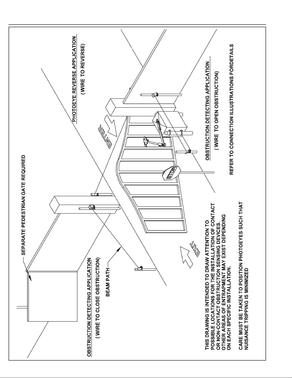
Photoeye Installation Illustration
SWG Swing Gate Operator Installation Guide
P1227 Revision X5 2-13-2013
- 20 -
Page 23

Dual Gate Installations
Optional In-Cabinet Heater
Two operators can be used in dual gate installations. The operators
communicate with each other through the 3-wire COMM LINK terminals.
When one operator activates, the COMM LINK connection signals
the other operator to activate. Each operator functions independently,
controlling its gate and monitoring its inputs and accessories.
A three-wire shielded conductor cable is required to connect two
operators together for dual operation. Use Belden 8760 Twisted Pair
Shielded Cable (or equivalent) only – P/N 2500-1982, per foot).
✓ NOTE: The shield wire should be connected COMM LINK terminal
“C” in both operators.
Three of the programming functions available are only used for dual gate
installations:
• Dual Gate Enable
Dual Gate Enable must be set for all dual gate installations.
• Stagger Mode
The Stagger Mode function determines if the operator has a delayed
open or a delayed close. In dual swing gate installations, typically one
operator is programmed for delayed open, and the other operator is
programmed for delayed close.
• Stagger Delay Time
The Stagger Time sets the length of the delay for the Stagger Mode.
See Pages 12 & 14 for details on these three dual gate programming
functions.
Set the following parameters in each gate operator individually in a single gate
mode before connecting the network cable and operating in dual gate mode.
1. Open and Close Limit settings
2. Open and Closed direction inherent
entrapment protection (OC & CC)
After these parameters have been set, and each operator has been
tested independently and is functioning correctly in single gate mode,
then set BOTH operators to dual gate (dg) in the Paired Mode setup step
under Basic Programming steps.
The operator can be ordered with an optional cold weather
package that includes an in-cabinet heater to keep the drive
train and electronics warm in cold environments.
In-cabinet heaters can also be ordered separately and
should be wired to the operator as shown in Figure 15
Contact Technical Services for heater wiring information for
a specifi c voltage and phase of operator.
SINGLE PHASE 115V, 208V, & 230V MODELS
(All heaters have built-in switch and thermostat)
BLACK
WHITE
115 VOLT HEATER (P/N 2510-262)
208/230 VOLT HEATER (P/N 2510-273)
THREE PHASE 208V & 230V MODELS
208/230 VOLT HEATER (P/N 2510-273)
THREE PHASE 460V MODELS
460 VOLT HEATER (P/N 2510-354)
CONNECT TO LEADS LABELED
"ACCESSORY POWER CONNECTION"
POWER BOX
CONTACTOR
CONTACTOR
Figure 15. In-cabinet Heater Wiring
DUAL GATE
COMM LINK
WIRING
CONNECT SHIELD
WIRE AT BOTH ENDS
SHIELD
CONNECT
C - C
B - B
A - A
SHIELD
USE BELDEN 8760 TWISTED PAIR
SHIELDED CABLE OR EQUIVALENT
Figure 14. COMM LINK Wiring
SWG Swing Gate Operator Installation Guide
OPERATOR #1
OPERATOR #2
- 21 -
P1227 Revision X5 2-13-2013
Page 24

Gate Operation
Open Button
Opens the gate. If the Controller is programmed to stop
opening the gate at mid-travel, a constant press of the OPEN
button will override the Mid-travel Stop and completely open
the gate. If the Auto Close Timer is set, it will be suspended
until the OPEN button is released.
Reverse Input
If the reverse input is triggered while the gate is closing, the
gate will reverse to the full open position. If the Auto Close
Timer is set, when the reverse input is cleared, the gate will
close when the Auto Close Timer expires.
Open Loop
Functions the same as the OPEN button.
Close Button
Closes the gate if the gate is open. Also closes the gate if
the gate is in the process of opening.
Stop Button
Stops the gate from opening or closing at any time.
Single Input
Opens the gate if it’s closed and closes the gate if it’s open
(open-close programming option). Activating the input while
the gate is moving will reverse the gate.
Can be programmed to stop the gate while the gate is
moving (open-stop-close programming option).
Fire Department Input
Fully opens the gate when the input is activated. Overrides
the Mid-travel Stop and Auto Close Timer (if either is
programmed for the gate). The gate will lockout in the open
position without sounding the alarm. Press the STOP button
to release the lockout.
Open Input
Functions the same as the OPEN button.
Open Obstruction
While the gate is opening, any open obstruction signal will
cause the gate to stop, reverse a short distance, and then
stop again. The Auto Close Timer will be disabled, and a
renewed input will be required to start the gate again. Should
the gate be restarted and the obstacle signal occur again
prior to reaching a limit, the gate will stop again, lockout,
and sound the emergency alarm.
Close Obstruction
While the gate is closing, any close obstruction signal will
cause the gate to stop, reverse, and travel to the full open
position. Should a open obstruction input or an open direction
inherent entrapment condition occur prior to the gate reaching
the open limit, the operator will lockout and sound the
continuous tone alarm. Another close request will be required
to start the operator again. If after restart, the overload or
a close obstacle happens again before the close limit is
reached, the operator will lockout and sound the alarm. If the
auto close timer is set, when the close obstruction input is
cleared, the gate will close when the auto close timer expires.
Reverse Loop
Functions the same as the reverse input.
Shadow/Reset Loop
Holds the gate fully open or fully closed while triggered.
If open, the gate closes immediately when cleared if
Anti-tailgate is enabled.
Operation Indications
During normal operation, the Controller’s displays will
indicate current operating conditions and status.
Power-up Display
When the Controller powers up, dashes will show on the
display, then the fi rmware version number, then the gate
type (SL for slide and swing gates).
Exiting programming restarts the Controller. The power-up
display will show upon the restart.
Idle Condition
While the Controller is idling, waiting for a command, the
display will show circulating dashes.
Last Gate Position/Condition
When the gate moves or stops, the display will show the
status for up to one minute.
• Stop is displayed as St
• Full Close is displayed as FC
• Full Open is displayed as FO
• Entrapment is displayed as En
Pre-start Delay
During the pre-start delay, the display will countdown the
number of seconds remaining before the operator starts.
Reverse Delay
If the gate travel direction is reversed from a user activation or
reversing device, and a reverse delay is set, the display will count
down the delay time in seconds before the operator restarts.
Run Timer
While the gate is opening or closing, the number of seconds
running time is displayed.
SWG Swing Gate Operator Installation Guide
P1227 Revision X5 2-13-2013
- 22 -
Page 25

Error Indications
During abnormal operation, the Controller’s displays and
beeper will indicate the error condition that has occurred.
Entrapment
If an entrapment condition occurs detected by two repeated
open or close obstruction triggers, the Controller will lock
the operator out. The beeper will sound constantly and the
gate will not operate. To reset the Controller press the STOP
button or press the RESET button on the operator’s cover.
WARNING
The Stop and/or Reset button must be located in the line-ofsight of the gate. Activation of the reset control shall not
cause the operator to start.
COMM LINK Connection Failure
In dual gate installations, if there is a connection failure
between the two operators, the COMM LINK indicator will
blink once a second. During this condition the gate will not
operate, except if triggered by the FIRE DEPT input, which
functions normally.
MGT Obstacle Transmitter Trouble
If any MGT transmitters are used with the operator, their
supervision feature will alert the Controller if there is any
trouble with the transmitter. MGT transmitters send hourly
status reports and will send low battery reports when the
transmitter has a low battery. The MGT transmitters also
have a tamper detection switch that will trigger when their
case is opened.
When the Controller detects a low transmitter battery, a
tamper signal, or missing transmitter status reports, the
gate will still operate normally, but the beeper will change
as follows:
• The Pre-start Alarm will beep twice as fast.
• The Run Alarm will beep twice as fast and continue for fi ve minutes
after the gate stops.
• The sounder will “chirp” every fi ve seconds when the gate is idle.
Correct the trouble (close case, replace battery, or replace
transmitter) to clear the obstacle transmitter trouble
indications.
CONTROLLER ERROR CAUSES AND INDICATIONS
ERROR CAUSE ERROR INDICATION HOW TO CLEAR
TWO SAFETY REVERSALS (ON
SINGLE GATE OR ON EITHER
DUAL GATE)
MAXIMUM RUN TIMER
EXCEEDED ON OPENING
MAXIMUM RUN TIMER
EXCEEDED ON CLOSING
COMM LINK FAILURE
GATE FULL OPEN RESULTING
FROM FIRE DEPT INPUT
FAIL SAFE OR FAIL SECURE
BECAUSE OF BATTERY VOLTAGE
DROP BELOW 21.6 VDC DUE TO
AC POWER LOSS
OTHER CONTROLLER IN
ENTRAPMENT (DUAL GATE)
LOW AC VOLTAGE AT
CONTROLLER
INPUT TRIGGERED DURING
ENTRAPMENT LOCKOUT
COMPATIBILITY PROBLEM En 09, GATE DISABLED
EEPROM PROBLEM En 10, GATE DISABLED TRY RESET, CALL TECH. SUPPORT
DC MOTOR MISMATCH En 11, GATE DISABLED
MOTOR FAILURE En 12, GATE DISABLED CALL TECH. SUPPORT
AC POWER LOSS IN OPEN OR
CLOSE IMMEDIATE POWER
FAIL MODE
MAXIMUM RUN TIMER
EXCEEDED AFTER AC POWER
LOSS
MGT SUPERVISORY CONDITION
(TAMPER, LOW BATTERY,
MISSING HOURLY STATUS)
En 00, CONTINUOUS ALARM
BEEPER, GATE DISABLED
En 01, AND MAX RUN LED,
CONTINUOUS ALARM BEEPER,
GATE DISABLED
En 02, AND MAX RUN LED,
CONTINUOUS ALARM BEEPER,
GATE DISABLED
En 03, AND COMM LINK LED,
CONTINUOUS ALARM BEEPER
FOR 1 MINUTE, GATE DISABLED
(EXCEPT FOR FIRE DEPT INPUT)
En 04, GATE DISABLED PRESS STOP BUTTON
En 05, GATE DISABLED
En 06, GATE DISABLED
En 07, GATE DISABLED
En 08, GATE DISABLED PRESS STOP BUTTON
En 13
En 14
FAST BEEPS DURING PRESTART,
FAST BEEP RUN ALARM, CHIRP
EVERY 5 SECONDS AT IDLE
PRESS STOP BUTTON
PRESS STOP BUTTON,
CLEARS CONTINUOUS ALARM,
THEN DOUBLE BEEP EVERY
5 SECONDS UNTIL NEXT
OPERATION
PRESS STOP BUTTON,
CLEARS CONTINUOUS ALARM,
THEN DOUBLE BEEP EVERY
5 SECONDS UNTIL NEXT
OPERATION
PRESS STOP BUTTON, CLEARS
CONTINUOUS ALARM
BATTERY VOLTAGE MUST RISE
ABOVE 24 VDC
CLEAR ENTRAPMENT ON OTHER
CONTROLLER (PRESS STOP)
RESTORE AC POWER TO
NORMAL LEVEL
UPDATE FIRMWARE AND RESET
BOTH PAIRED CONTROLLERS
REPROGRAM MOTOR TYPE OR
CHANGE DC MOTOR BOARD,
NEXT GATE MOVEMENT WILL
RETRY DC MOTOR CHECK
REAPPLY AC POWER
BATTERY VOLTAGE MUST RISE
ABOVE 24 VOLTS
CLEARS WHEN MGT CONDITION
CLEARS
Maximum Run Time Exceeded
If the Maximum Run Time is exceeded, the Controller stops
the operator the same as if a double obstacle has occurred
in an entrapment condition. The entrapment alarm sounds
constantly, and is cleared by pressing the STOP button or the
RESET button on the cover. After the STOP or RESET button
is pressed, because the Maximum Run Time has been
exceeded, the sounder will beep twice every fi ve seconds.
The next operation of the gate will clear the indication.
SWG Swing Gate Operator Installation Guide
- 23 -
P1227 Revision X5 2-13-2013
Page 26

Troubleshooting
Contacting Technical Support
For technical questions regarding Linear gate operators, contact the
Technical Services Department at:
1-800-421-1587
Operator fails to start
A. If the operator has been running a large number
of cycles, the motor may have become too hot and
tripped its thermal overload breaker. Allow the motor to
cool down and the thermal overload breaker will reset
automatically.
B. Make sure you have power at the master distribution
panel and that the power has not been turned off.
Motor operates, but gate does not move
A. In operators with torque limiters and friction pad clutches,
check for signs of slipping. You can mark the sprocket
and clutch with a yellow or white grease pen and watch
for the lines to move apart if slipping is taking place.
Adjust the torque limiter tighter if this is the problem.
B. Check for broken chain or worn belts.
C. Check all setscrews on pulleys and sprockets and tighten
them if necessary, and check for keys which may have
fallen loose from keyways.
Motor sounds like it is working harder than normal
A. Make sure the gate is moving freely and without binding
throughout its entire travel.
B. Check the drive chain for obstructions (if the operator
has one).
C. If the operator has an internal brake mechanism, make
sure it is releasing.
from 5:00 AM to 4:30 PM Pacifi c time
Gate stopping part way open or closed
(but no visible obstruction)
A. The Controller may have received a false obstruction
input triggered by current sensing set too low. Make sure
the gate moves freely through its entire travel before
adjusting the current sensing.
B. The Maximum Run Timer may have counted down and
expired. This can be caused by having the timer set too
low, if a chain or belt is broken, or if a sprocket or pulley
is slipping. When the timer expires, the gate stops and
the beeper will sound.
C. An obstruction signal from an accessory wired to the
obstruction input may have triggered falsely. Check the
control board for lit indicators for any of the following
inputs: safety, shadow/reset, open obstruction, close
obstruction, stop, etc. If any are lit when the operator
should be running, remove all devices hooked to that
function and hook them up one at a time and try to run
the operator until the problem device is found. Refer to
Page 9 for details on the control board indicators.
Gate staying open with automatic system
A. If there are vehicle detectors used with the operator, one
of the loops or loop detectors may be sending a false
signal or needs to be reset. Observe the indicators on
the loop detector. Unplug the detector and try running
the operator.
B. An opening or reversing device may be stuck or
malfunctioning. Try disconnecting these devices and
hook them back up one at a time and try running the
operator until the malfunctioning device is found.
C. Make sure the close limit switch isn’t activated. If it is, the
operator will think the gate is already closed.
Limit switch getting out of time
A. Check the setscrews in limit cams for tightness. Replace
if necessary.
How to Order Replacement Parts
Use the part numbers listed on the following pages.
Contact your local Linear dealer or distributor to order parts.
1. Supply the model number and serial number of your operator.
2. Specify the quantity of pieces needed and order by part number and name of part.
3. State whether to ship by freight, truck, parcel post, UPS or air express.
4. State whether transportation charges are to be prepaid or collect.
5. Specify name and address of person or company to whom parts are to be shipped.
6. Specify name and address of person or company to whom invoice is to be sent.
SWG Swing Gate Operator Installation Guide
- 24 -
P1227 Revision X5 2-13-2013
Page 27

Preventative Maintenance
WARNING
Always disconnect power from operator before servicing.
Keep clear of gate during operation.
General
Linear gate operators are designed for many years of
trouble-free operation and, under recommended operating
conditions, will require only minimal maintenance. To ensure
that a unit is ready for operation at all times, and to preclude
serious damage or failure, inspect the unit systematically.
Proper adjustments and lubrication should be made as
recommended.
Lubrication
✓ Bearings — For models which have pillow block style
bearings with grease fi ttings, lubricate at least twice a
year with a lithium complex based, petroleum oil NLGI 2
rated grease. Oilite and precision sealed bearings do not
require additional lubrication.
✓ Motor — Motors have sealed ball bearings and do not
require further lubrication. If bearing noise develops after
several years of operation, bearings should be replaced
by a motor repair company, or the motor should be
replaced if necessary.
✓ Swing Gate Arm — Check all bolts for proper tension
and tighten if necessary. Make sure the arm folds
overextends itself slightly against the overtravel stop
to reduce the chance that the gate can be backdriven
open. Adjust the close limit slightly if additional travel
is required. Lightly lubricate all pivot points with a light
machine oil.
6-Month Preventative Maintenance
1. For operators which utilize torque limiting clutches,
check for proper tightness. If there appears to be dust
from wear on the pads, inspect the pads and replace
if necessary. If the clutch cannot be adjusted tightly
enough to move the gate without slipping, the pads must
be replaced.
2. For operators with V-belts, inspect for wear and replace
as necessary. Check for proper tension and adjust if
required. Check all pulley setscrews for tightness and
tighten if necessary.
3. For operators with internal chain drives, inspect chain
and sprockets for wear and replace if necessary. Check
for proper tension and alignment, and adjust if required.
Check all hub sprocket setscrews and tighten if required.
4. Check limit switches and limit actuators (cams, limit nuts,
etc.) for wear and replace as required. In rotary limit
switch assemblies, wipe the limit shaft clean and apply a
light coating of dry lubricant.
5. For operators with magnetic brakes, check for proper
adjustment. Brake disc must run free when the brake
is engaged. For brake assemblies other than C-face
style, the brake should be adjusted so that the solenoid
plunger throw is between 3/8” to 1/2”. Too much throw
will damage the solenoid. If the solenoid emits a loud
buzzing sound when the motor is run, the brake
must be adjusted.
6. In operators which have a disconnect handle, inspect
disconnect handle for proper function and lubricate if
necessary. Use a lithium based grease on all moving
parts.
7. Inspect all nuts and bolts for proper tightness and tighten
as necessary.
8. Check all reversing devices for proper function. Inspect
all contact edges for wear and replace if required. Check
photoeyes for proper alignment and function.
9. Check current sensing for proper adjustment when
fi nished with inspection and maintenance.
10. Inspect the installation area. Are all the warning signs
intact and visible? If they are missing or need replaced,
contact Linear. Be sure there are no control stations
mounted within reach of the gate. Review safety literature
with the customer and advise them to remove any such
stations found.
For all gate operators, you must
inspect the gate for proper operation.
The gate should move easily without
binding through its entire travel. If
the gate does bind, adjust or fi x as
required. Failure to keep the gate in
good working condition will have
adverse effects on the operator.
SWG Swing Gate Operator Installation Guide
FCC Notice
This device complies with FCC Rules Part 15 and Industry
Canada Rules & Regulations. Operation is subject to the
following two conditions: (1) This device may not cause
harmful interference and (2) this device must accept any
interference received, including interference that may cause
undesired operation.
- 25 -
P1227 Revision X5 2-13-2013
Page 28

Model SWG Exploded View
SWG Swing Gate Operator Installation Guide
P1227 Revision X5 2-13-2013
- 26 -
Page 29

MODEL SWG MECHANICAL PARTS LIST
REF. # PART # DESCRIPTION
2120-361-BT Complete Enclosure Assembly with Door
1 2110-067-BT Enclosure Assembly without Door
2120-362-BT Enclosure Door and Lock Assembly
2300-716 Stop/Reset Button Cover
2 2110-164 Mounting Plate
4 2110-163 Bearing Spacer & Bracket Assembly, 3”
14 2110-173 Bearing Spacer & Bracket Assembly, 2”
15 2100-1034 Bearing Spacer, 2”
17 2100-708 Main Frame Mounting Bracket
25 2100-1414 Reducer Spacer Plate
3 2110-566
2100-1913-BT Crank
27 2200-016 Moisture Seal
26 2100-1344 Moisture Seal Spacer
19 2200-224 Set Collar, 1-1/8” ID
5 2200-264 Pillow Block Bearing, 1-1/8”
6 2110-144 Limit Cam
16 2110-130 Intermediate Shaft Assembly
2100-688 Intermediate Shaft
2200-279 Sprocket, 40-B-9, 3/4” bore
13 2200-222 Pillow Block Bearing, 3/4”
7 2200-584 Torque Limiter
12 2200-281 Sprocket, 40-A-36
35 2400-520 E-Ring, 3/4”
11 2200-097 Gear Reducer, 60:1
9 2200-084 Sprocket, 40-B-13, 1” bore
2100-206 #40 Chain, 30 Links
2200-467 #40 Chain, 22-1/2”
2200-006 #40 Master Link
2400-254 Key, 3/16” x 3/16” x 3”
2400-201 Key, 1/4” x 1/4” x 1-1/2”
Output Shaft Welded Assembly:
1-1/8” bore with 40-B-48 Sprocket
REF. # PART # DESCRIPTION
28 2500-764 Limit Switch
29 2100-586 Limit Bracket
30 2510-248 Stop/Reset Button and Bracket Assembly
2100-1760 Stop/Reset Button Mounting Bracket
2500-1495 Stop/Reset Button
32 2100-1683 Left Mounting Bracket
33 2100-1773 Right Mounting Bracket with Shelf
C-Face Motors
10 2500-2307 1/2 HP, 115V, 1 Phase
2500-2308 1/2 HP, 208/230V, 1 Phase
2500-2309 3/4 HP, 115V, 1 Phase
2500-2310 3/4 HP, 208/230V, 1 Phase
2500-2311 1 HP, 115V, 1 Phase
2500-2312 1 HP, 208/230V, 1 Phase
2500-2313 1/2 HP, 208/230/460V, 3 Phase
2500-2314 3/4 HP, 208/230/460V, 3 Phase
2500-2315 1 HP, 208/230/460V, 3 Phase
Capacitors
2500-2336 Capacitor for 2500-2307 Motor
2500-2337 Capacitor for 2500-2308 Motor
2500-1926 Capacitor #1 for 2500-2309 Motor
2500-1930 Capacitor #2 for 2500-2309 Motor
2500-1931 Capacitor for 2500-2310 Motor
2500-2338 Capacitor for 2500-2311 Motor
2500-1932 Capacitor for 2500-2312 Motor
SWG Swing Gate Operator Installation Guide
- 27 -
P1227 Revision X5 2-13-2013
Page 30

Single Phase Controller Parts List
OPEN/RESET
SHADOW/RESET
2
ON 115V
MODELS
ONLY
1
5
4
SINGLE PHASE CONTROLLER MECHANICAL PARTS LIST
REF. # PART # DESCRIPTION
1 2500-2393 Apex Module
2510-422 115V Power Box Assembly
2
2510-430 208/230V Power Box Assembly
3 2100-2143 Power Box Mounting Strap
4 2300-1025 Apex Plastic Cover
5 2510-423 Cover Knob Kit
6 2520-526 Complete Wiring Harness Assembly (not shown)
3
SWG Swing Gate Operator Installation Guide
P1227 Revision X5 2-13-2013
- 28 -
Page 31

Three Phase Controller Parts List
1
3
8
5
2
6
OPEN/RESET
SHADOW/RESET
9
4
7
THREE PHASE CONTROLLER MECHANICAL PARTS LIST
REF. # PART # DESCRIPTION
1
2 2100-2148 Cover
3 2500-2393 Apex Module
4 2500-1980 Motor Board
5 2500-034 Power Switch
6
7 2500-2084 Contactor
8 2510-423 Cover Knob Kit
9 2300-1025 Apex Plastic Cover
SWG Swing Gate Operator Installation Guide
2520-530 Control Box Assembly (Complete) 208/230V
2520-531 Control Box Assembly (Complete) 460V
2100-2147 Control Box Assembly (Box only)
2500-767 Transformer 208/230V
2500-768 Transformer 460V
- 29 -
P1227 Revision X5 2-13-2013
Page 32

Gate Arm Assembly Parts List
NOTE: CRANK SHOWN
FOR REFERENCE ONLY
GATE ARM ASSEMBLY MECHANICAL PARTS LIST
REF. # PART # DESCRIPTION
2120-449-BT Complete Arm Assembly
1 2100-1913-BT Crank (not included in arm assembly)
2 2100-1722-BT Crank Extension
3 2100-1924-BT Overtravel Stop
4 2100-1597 Gate Arm Clamp
5 2100-1733-BT Gate Plate
6 2200-783 Spacer - black, 1/2” ID x 3/4” OD x 9/16” LTB
7 2400-378 Set Bolt, 5/16”-18 x 3/4”
8 2400-376 Flat Washer
9 2100-1547 Disconnect Pin
10 2400-351 Disconnect Hair Pin
2200-034 Disconnect Lock (optional)
11 2100-122-BT Pipe Link, 1”
12 2400-380 HHCS, 1/2”-13 x 1-3/4”
13 2400-418 Nylon Lock Nut, 1/2”
14 2300-238 Nylon Washer, 3/4” ID
15 2400-433 Split Lock Washer, 1/2”
16 2400-434 HHCS, 1/2-13 x 1-1/4”
17 2400-482 HHCS, 1/2-13 x 2-1/2”
18 2100-1725 Spacer - yellow, 3/4” OD x 1/2” ID x 3/4” LTB
19 2100-1932-BC Spacer - black, 1 1/4” OD x 1/2” ID x 1/2” LTB
20 2100-1320 Spacer - zinc-silver, 3/4” OD x 1/2” ID x 1/2” LTB
21 2400-309 Set Screw, 1/4” - 20 x 1/2”
SWG Swing Gate Operator Installation Guide
P1227 Revision X5 2-13-2013
- 30 -
Page 33

This page intentionally
left blank.
SWG Swing Gate Operator Installation Guide
- 31 -
P1227 Revision X5 2-13-2013
Page 34

Gate Operator Installation Checklist
INSTALLER CUSTOMER
❑
❑
❑
❑
❑
❑
❑
1. The gate has been checked to make sure it is level and moves freely in both directions.
❑
2. Potential pinch areas have been guarded so as to be inaccessible OR have
❑
3. The installer has installed one or more contact or non-contact obstruction sensing
❑
4. If pedestrian traffi c is expected, a separate pedestrian gate has been
❑
5. Warning signs have been installed on each side of the gate in highly visible locations.
❑
6. There are no controls installed on the gate operator, or within seven feet of the gate.
❑
7. The installer has properly adjusted the obstruction sensing feature and has tested
❑
contact and/or non-contact obstruction sensing devices installed.
devices, in compliance with UL325 requirements for this installation.
installed, a minimum of seven feet from the gate. The customer has been
informed that all pedestrian traffi c must use the pedestrian gate.
The customer has been informed that these signs must remain at all times.
the gate to make sure that the gate stops and reverses a short distance with minimal
resistance applied (40 lbs. on a swing gate at the end of the gate, 75 lbs. on a slide gate)
By signing this installation checklist, I/we hereby certify that each item listed and checked above has been covered by the
installer and is clearly understood by the customer.
❑
❑
❑
❑
❑
8. The installer has instructed the customer in the proper use of the gate operator and reviewed
❑
9. The installer has instructed the customer in the proper use of the operator’s
❑
10. The installer has reviewed all safety instructions with the customer, and has left
❑
11. The installer has answered any questions the customer has regarding the
❑
12. The installer has explained to the customer that a regular maintenance
❑
all of the operational functions, obstruction sensing devices, warning beeper and reset, etc.
manual disconnect feature. The manual disconnect must never be used
while the gate is in motion. The power switch must be turned off before
using the manual disconnect and disengaging the operator.
the safety instructions and owner’s information sheets for their reference.
operation of the gate operator and gate operator safety precautions.
schedule for both the gate and the gate operator is recommended.
Customer’s Signature
Installer’s Signature
SWG Swing Gate Operator Installation Guide
Date
Date
P1227 Revision X5 2-13-2013
- 32 -
 Loading...