

Page 1
SPX-7500 Series
Operations Manual
Suprex® Reader Extender - RS-485 Interface
SPX-7500_MAN_082112
Page 2

Cypress Suprex SPX-7500 Series
Physical
SPX-7500 ! - Aluminum Enclosure
4.45” x 3.08” x 2.0”
Temp
Storage(-55˚C to + 150˚C)
Operating(-40˚C to +80˚C)
Humidity
95% (non-condensing)
Power
Input
Unreg Input 8 to 16 VDC* @ 300mA Max
Power
Output
+5VDC @100mA
Data I/O
Interface
Reader -Wiegand, Strobed (Clock & Data),
F/2F
LED - 0 - 30V
SPX-7500 Series:
This manual covers the operation and setup of the Cypress Suprex RS-485 based SPX-7500 series units.
Features:
-- Supports 1 reader and associated I/O.
-- Expandable to 8 total readers and associated i/O with EXP-2000 modules
-- Service mode for setup and configuration of Expansion modules.
-- Field configurable reader formats
-- Multifunction indicator for determining operational status of the unit
-- Auxiliary I/O connections available for Door/Gate/Panel status signaling.
Electrical and Mechanical Specifications
* See notes on following page for temperature and power ratings
Cypress Computer Systems, Inc. ⌖ Lapeer, MI 48446 ⌖ www.cypresscomputer.com
© 2012 Cypress Computer Systems Inc.
Page 3
Switch
6 7 8
0
1 x
2 x
3 x x
4 x
5 x x
6 x x
7 x x x
Wiegand
Wiegand / No Filter
Strobed Rising Edge (MR-5)
Strobed Rising Edge (Dorad0 644)
Strobed Rising (Mag-Tek)
Strobed Falling Edge
Reserved
F2F
x = ON
1234567
8
Dip switch #4 is ON
-Disable Pullup resistors
Dip switch #4 is OFF
-Enable Pullup resistors
Switch
6 7 8
0
1 x
2 x
3 x x
4 x
5 x x
6 x x
7 x x x
Wiegand
Wiegand / No Filter
Strobed Rising Edge (MR-5)
Strobed Rising Edge (Dorad0 644)
Strobed Rising (Mag-Tek)
Strobed Falling Edge
Reserved
F2F
x = ON
1234567
8
Dip switch #4 is ON
-Enable Pullup resistors
Dip switch #4 is OFF
-Disable Pullup resistors
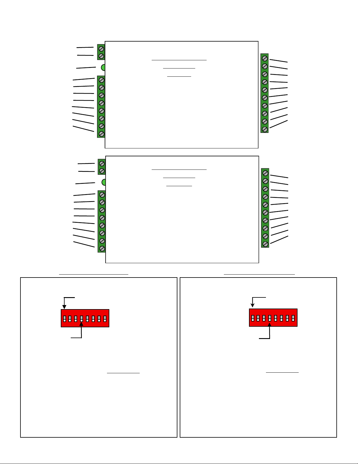
1 - 8 to 16 VDC In
2 - Ground
Status LED
1 - exp (+)
2 - exp (-)
3 - +5 VDC out
4 - Prog Res 4
5 - Prog Res 3
6 - LED In
7 - D1/Data out
8 - D0/Clk out
External Reader / Panel connections and DIP Switch Settings
RS-485 Interface
SPX-7500
Central
1- Relay 4 N.O.
2- Relay 4 Com
3 - Relay 4 N.C.
4 - Relay 3 N.O.
5 - Relay 3 Com
6 - Relay 3 N.C.
7 - Ground
8 - Aux out
9 - R2 in
10 - R1 in
1 - 8 to 16 VDC In
2 - Ground
Status LED
1 - exp (+)
2 - exp (-)
3 - +5 VDC out
4 - R4
5 - R3
6 - LED out
7 - D1/Data In
8 - D0/Clk In
Central Unit Settings
DIP Switch #1 OFF
See appendix for
Expansion module Setup
RS-485 Interface
SPX-7500
Remote
1- Relay 2 N.O.
2- Relay 2 Com
3 - Relay 2 N.C.
4 - Relay 1 N.O.
5 - Relay 1 Com
6 - Relay 1 N.C.
7 - Ground
8 - Aux in
9 - Not used
10 - Not used
Remote Unit Settings
DIP Switch #1 OFF
See appendix for
Expansion module Setup
Page 4
Ground
DC
Ground
Power
Supply
Access
Control
Panel
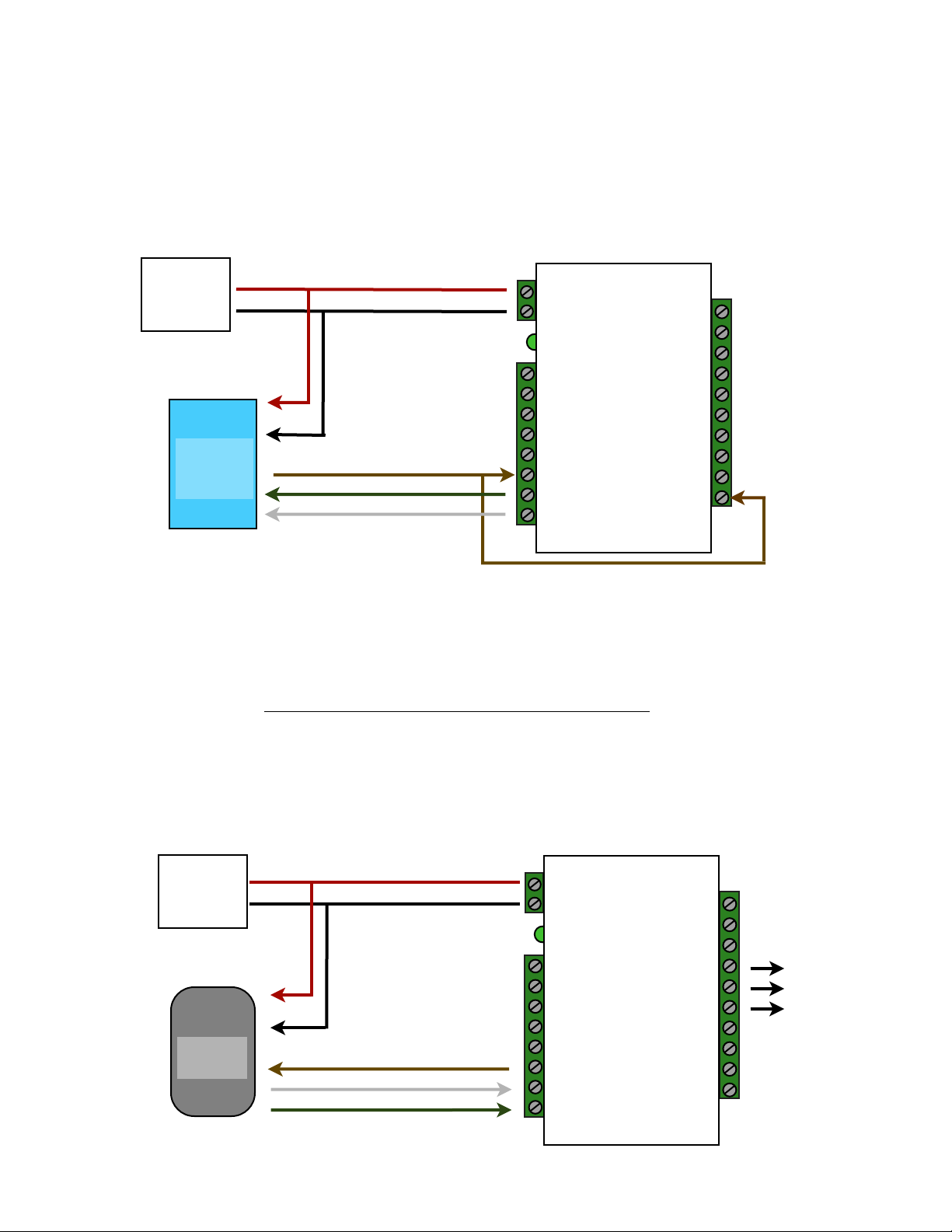
Quick Reference For Typical Connections
SPX-7500 Series Central
+8 to +16 VDC
Diagnostic LED
LED In
D1/Data Out
D0/Clock Out
R1 Input
Controls
Strike on
Remote
R1 IN
DC
Power
Supply
Card
Reader
See page 10 for other strike control options
SPX-7500 Series Remote
+8 to +16 VDC
Diagnostic LED
LED Out
D1/Data In
D0/Clock In
R1 N.O.
R1 Com
R1 N.C.
Door
Strike
Output
Page 5
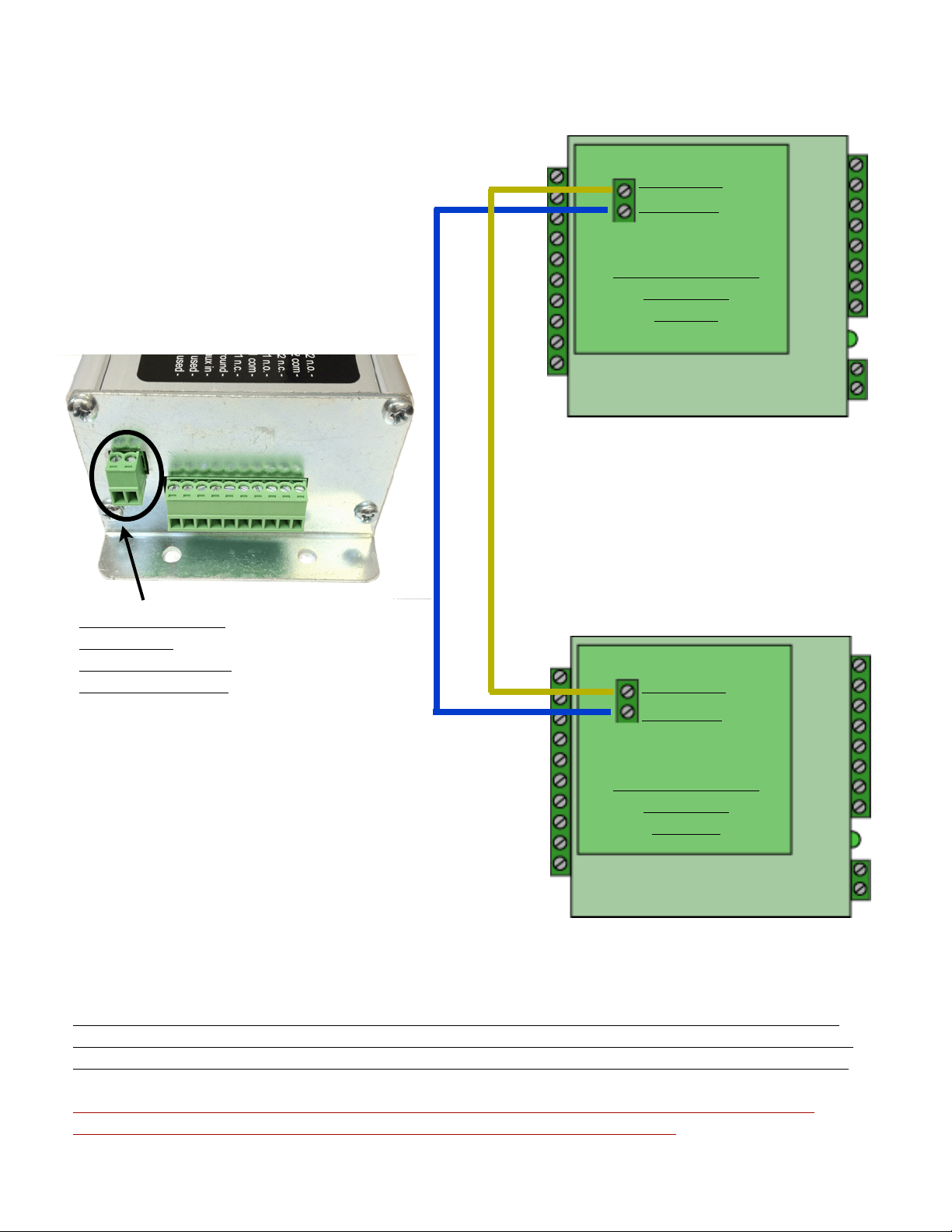
RS-485 GATEWAY Data Connections
RS-485 (+)
RS-485 (-)
RS-485 Interface
SPX-7500
Central
RS-485 Interface
to connect
SPX-7500 remote
and central units
RS-485 (+)
RS-485 (-)
RS-485 Interface
SPX-7500
Remote
The SPX-7500 utilizes an RS-485 connection to provide a data link between the Central
and Remote RFX units. This RS-485 connection provides a data connection in the same
manner as other suprex products that use IP Newtwork, RF, or Fiber-Optic connections.
Note: The Gateway RS-485 data connection is entirely separate from the expansion
module RS-485 data connection. They are entirely different circuits.
Page 6
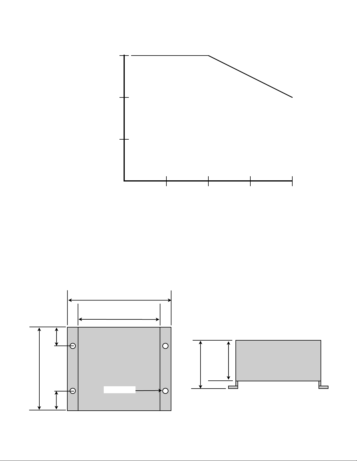
810121416805535-40
Ambient Temperature
(Degrees Celsius)
Supply Voltage
Temperature/Voltage de-rating curve
Temperature Rating vs Voltage Derating Curve
4.45
3.15
0.80
3.08
1.70
2.00
The Suprex units should be operated with a filtered 12 Volt nominal DC supply.
Any voltage between 8 and 16 volts can be utilized by following the temperature /voltage derating curve.
Voltage should not exceed 16 VDC under normal operating conditions.
Cypress Suprex® SPX-7500 Enclosure Dimensions
ø0.20 X 4
Page 7

Cypress Suprex SPX-7500 Series - Setup and Pre-installation
Bench Testing:
Before installing the units in the field they should be assembled and tested at a convenient “Bench top” location. This
will make it easier to verify / change settings and check operation when both units are visible at the same time.
It is also a chance to become familiar with the system if this is the first time using the Suprex system. It is much more
difficult to setup and test the units when they are several thousand feet apart.
1. Connect the Remote and Central unit RS-485 ports together as per the RS-485 Gateway Connection Diagram.
The Gateway RS-485 connections are located on the Daughterboard attached to the RFX-7500.
2. Connect a suitable power supply to both units. Each unit should be provided with 8 - 16 volts DC and a minimum
of 500mA.
3. Apply power. After about a short delay, both units Diagnostic LED should indicate communication by illuminating
with a periodic Green pulse.
5. Touch a jumper wire from the Ground connection the the Relay 1 input on the Central unit. Relay #1 on the
Remote unit should activate with an audible click. A VOM or continuity tester should show the Relay #1 normally
open contacts on the Remote unit closing when the Relay #1 input is activated (connected to ground) on the
Central unit.
6. Units are shipped from the factory set for the Wiegand data format. If a different format is required set the DIP
switch to the required reader and panel format.
7. If a reader and panel is accessible, connect the reader to the Remote unit and the Central unit to the panel and
verify that card reads are being accepted by the access control system. If any troubleshooting is necessary, it will
be easier to do with both units in close proximity to each other.
8. If Expansion modules are used with the system, refer to the Expansion Module Appendix in this manual.
9. Once these steps are completed, the units are ready for installation it their permanent locations and final
commissioning as a system.
Page 8

Cypress Suprex SPX-7500 Series - Status Indicators
LED Diagnostic Indicator:
The LED Diagnostic indicator provides information on the operational status of the unit.
If the units are not communicating, viewing the diagnostic indicator LED’s may help to determine the
nature of the problem.
When the Suprex units are operating correctly and have a valid communication channel between
the Remote and Central units, the Diagnostic indicators on each unit will flash green rapidly
(2-3 flashed per second).
DIAGNOSTIC LED NOT ILLUMINATED:
If the LED(s) are not illuminated on the unit(s) then the unit is not getting power or there is an electrical problem.
The Diagnostic LED’s will be illuminated Red/Green or flashing whenever power is applied.
CENTRAL UNIT FLASHING BETWEEN RED/GREEN:
With power applied and no communication path between the Remote and Central, the Central unit will flash the
diagnostic indicator alternately between Red and Green.
REMOTE UNIT ILLUMINATED RED:
The Remote unit will diagnostic LED will illuminate solid (not flashing) red if it is not receiving communication from
the Central.
REMOTE AND CENTRAL UNITS FLASHING BETWEEN RED/GREEN:
The Central is not Receiving communication from the Remote.
Page 9

Cypress Suprex 7500 Series - Door Strike and LED I/O
To activate the relay on the Remote unit, connect as shown below. These connections can be used
to allow the Remote relay to operate a DOOR STRIKE, GATE, or other locking hardware. Refer to
following pages in this document for details of each I/O operation and connection.
There are two relays available for accessory outputs at the Remote end. Either relay can be used
to provide the Door Strike or Gate activation function. This example uses Relay 1.
Wiring Example - Door Strike Follows LED
Ground
Suprex Central
R1 Input
Access
Control
Panel
Ground
LED Signal
LED In
Controls
Strike on
Remote
R1 IN
Only Relay and LED Connections are shown for clarity, refer to previous diagrams for Power and Data connections.
Wiring Example - Door Strike does not follow LED
Ground
Suprex Central
Access
Control
Panel
N.O.
Com
Ground
LED Signal
Strike Signal
Ground
LED In
R1 Input
Controls
Strike on
Remote
Ground
R1 IN
Page 10

Cypress Suprex 7500 Series - Door Strike and LED I/O
The Cypress SPX-7500 provides additional data channels to support access control hardware such as door strikes, tamper
alarms, request to exit status, etc. These signals are sent to and from the Remote and Central units without the need to run
additional wiring.
The accessory control I/O use active low inputs. When the inputs are floating (nothing connected) the associated output will be
set to a high level. When the input is set to 0Volts (Ground) the input will activate its associated output. All Accessory outputs
are Open Collector type and will switch to Ground when activated.
Each input will have an associated output. See the following pages for a diagram of each I/O pair.Inputs can be tested by
making a jumper connection to ground and monitoring the associated output.
Suprex® Central
Ground
Jumper to ground to test
Input
Output
LED In
Red arrow denotes direction of command signal
Suprex® Remote
LED Out
Page 11

Cypress Suprex Series - Relay Controls
Suprex® Central
Relay 1 IN
Suprex® Remote
Relay 1 N.O.
Relay 1 Com
Relay 1 N.C.
Suprex® Central
Relay 2 IN
Input Signal
Input Signal
Red arrow denotes direction
of command signal
Relay 2 N.O.
Relay 2 Com
Relay 2 N.C.
Contact
Outputs
Suprex® Remote
Contact
Outputs
Page 12

Cypress Suprex Series - Relay Controls
Suprex® Central
Relay 3 N.O.
Relay 3 Com
Relay 3 N.C.
Relay 4 N.O.
Relay 4 Com
Relay 4 N.C.
Contact
Outputs
Suprex® Central
Contact
Outputs
Red arrow denotes direction
of command signal
Input Signal
(5Volts DC
Maximum)
Suprex® Remote
Relay 3 IN
Input Signal
(5Volts DC
Maximum)
Suprex® Remote
Relay 4 IN
Relay 3 functions as an Alarm relay and monitors the condition of the communication link between
the Central and Remote units. Relay 3 is activated when power is applied and the communication link between
the Central and Remote is functioning. Relay 3 will become deactivated (Alarm condition)
when either the Relay 3 input on the remote is active OR the Remote unit is unable to communicate with the
Central unit. See APP NOTE FOR DETAILS
Page 13

1K
Ground
SPX-XXXX Application Note
R1 in
Using Supervised Contacts with the SPX-series Extenders
Applies to the following products: SPX-5501, SPX-5601, SPX-5521, SPX-5621, SPX-7400,
SPX-7410, SPX-7200, SPX-7500, All RIM series products.
This application note describes the connections necessary to convey supervised contact status over
a Suprex® communication link. The configurations described in this app note should apply to most
panels that utilize supervised contacts. When connected as described, the Suprex® system will
provide a supervised signal to the panel interface by reading the supervised status of the contacts
connected to the Suprex® Remote unit.
Theory of operation: The Access control panel is looking for a certain value of resistance
connected to the supervised contact terminals. The Suprex® Central unit will provide these
resistance values locally at the panel so that the correct supervised status is maintained. At the
same time, the Remote unit must maintain supervision of the wires connected to the relays and
switches that are connected to the remote access point. The contact supervision is provided by the
Remote unit. The Suprex® system does this by comparing the value of programming resistor at the
Central unit with the resistance seen at the Remote interface terminals. When there is a difference
in the two values, the Relay on the Central unit is activated.
There are two different examples. One example is monitoring a normally closed contact at the
Remote unit, and the other example is monitoring a normally open contact at the Remote unit. In
the examples given, a normally closed contact will require a programming resistor of 1K and a
normally open contact will require a programming resistor of 2K. Other resistor values can be used
but 1K resistors are the most common. Other resistance values will require different value(s) for the
programming resistor(s).
2K
Door
Contact
N.O.
Contact
1K
N.C.
Rex
8 to 16 VDC In
Ground
exp (+)
exp (-)
+5 VDC out
Prog Res 4
Prog Res 3
LED In
D1/Data out
D0/Clk out
Central Unit
1K
1K
1K
Relay 4 N.O.
Relay 4 Com
Relay 4 N.C.
Relay 3 N.O.
Relay 3 Com
Relay 3 N.C.
Ground
Aux out
8 to 16 VDC In
Diagnostic LED
exp (+)
exp (-)
+5 VDC out
R4
R3
LED out
D1/Data In
D0/Clk In
R2 in
Remote Unit
I1-
1K
I1+
I2-
1K
I2+
Relay 2 N.O.
Relay 2 Com
Relay 2 N.C.
Relay 1 N.O.
Relay 1 Com
Relay 1 N.C.
Ground
Aux in
Not used
Not used
Page 14

SPX-7500 Setup - Using Expansion Modules
1234567
8
Before using EXP-2000 Expansion modules with the SPX-7500 system, it will be necessary to perform a short
configuration process. This process determines if the 7500 will utilize expansion modules, and if so, how many will be
used with the system. Each SPX-7500 link can support up to 8 expansion modules.
SPX-7500 units are shipped in the factory default condition. Factory default units will be setup to function as
SPX-7500 units without expansion modules. Only communications between the 2 gateway units will be active.
Setup Process:
1. With power off, set the DIP switch on the Central unit according to the table below.
2. Apply power.
The Diagnostic LED should display a steady Green indication.
3. Remove power
Set DIP switch #1 OFF. Any other DIP switches can now be set as required (Reader family/ Pullup resistors).
The Central unit is now configured. No expansion module configuration is required for the Remote unit.
4. The expansion modules will need to be setup and correctly addressed. See EXP-2000 manual for details of
Expansion module setup and configuration. The Expansion units are addressed, and added to the system as pairs.
5. Connect the Expansion modules into the system as indicated in this wiring diagram.
Operation with Expansion Modules:
The SPX-7500 system Remote and Central gateway units will operate as a standard pair Suprex units, all of the I/O
and data terminals are available for use with readers and access control systems. There are some minor differences
in operation when using the expansion modules.
1. The Diagnostic LED on the Gateway units will indicate the status of the main (gateway) communication link only.
2. The Alarm relay on the Central Gateway unit will deactivate (indicate alarm condition) when the communication fails
between the Gateway units or ANY of the the Remote or Central Expansion units.
3. Paired Expansion units will be functionally similar to the standard SPX-1300 Wiegand Suprex system.
Central Unit Configuration Mode Settings
" " " Switch
"""1 2 3 4 5 6 7 8
Gateway only - No EXP" 1 0 0 1 0 0 0 0
1 EXP Pair used " " 1 0 0 1 0 0 0 1
2 EXP Pair used" " 1 0 0 1 0 0 1 0
3 EXP Pair used" " 1 0 0 1 0 0 1 1
1 = ON
0 = OFF
4 EXP Pair used" " 1 0 0 1 0 1 0 0
5 EXP Pair used" " 1 0 0 1 0 1 0 1
6 EXP Pair used" " 1 0 0 1 0 1 1 0
7 EXP Pair used" " 1 0 0 1 0 1 1 1
Page 15

*
R1 Input
Controls
Strike on
Remote
Cypress Suprex Series - Wiegand Expansion Module
Panel “Central” interface
D0/Clock Out
R1 IN
D1/Data Out
LED In
485(-)
485(+)
Access
Control
Panel
Ground
+8 to +16 VDC
8 to 16 VDC In
Ground
485(+)
485(-)
+5 VDC Out
Prog Res 4
Prog Res 3
LED Input
D1 Output
D0 Output
EXP-2000
Central Unit
DC
Power
Supply
RLY4 N.O.
RLY4 Com
RLY4 N.C.
RLY3 N.O.
RLY3 Com
RLY3 N.C.
RS232 Out
RS232 In
Ground
Aux Out
Relay2 Input
Relay1 Input
Page 16

*
D0 Input
Door
Strike
Output
Cypress Suprex Series - Wiegand Expansion Module
Reader/Door “Remote” interface
D0/Clock In
D1/Data In
LED Out
R1 N.C.
R1 Com
R1 N.O.
485(-)
485(+)
Card
Reader
Ground
+8 to +16 VDC
8 to 16 VDC In
Ground
485(+)
485(-)
+5 VDC Out
RLY4 Input (5V)
RLY3 Input (5V)
LED Output
D1 Input
EXP-2000
Remote Unit
DC
Power
Supply
RLY2 N.O.
RLY2 Com
RLY2 N.C.
RLY1 N.O.
RLY1 Com
RLY1 N.C.
RS232 Out
RS232 In
Ground
Aux In
N/C
N/C
Page 17

 Loading...