

Page 1

ENGLISH
1
CE DECLARATION OF CONFORMITY FOR MACHINES ................................................................................................. 2
WARNINGS FOR THE INSTALLER ................................................................................................................................. 2
1 DESCRIPTION ........................................................................................................................................................ 3
2 TECHNICAL SPECIFICATIONS ................................................................................................................................. 4
3 DIMENSIONS ........................................................................................................................................................4
3.1 STANDARD VERSION ........................................................................................................................................ 4
3.2 VERSION WITH MECHANICAL RELEASE ............................................................................................................. 4
4 ELECTRICAL PREPARATIONS ................................................................................................................................... 4
5 INSTALLING THE AUTOMATED SYSTEM ................................................................................................................... 4
5.1 PRELIMINARY CHECKS ..................................................................................................................................... 4
5.2 WALLING IN THE BEARING CASE ...................................................................................................................... 4
5.3 FITTING THE GATE ............................................................................................................................................5
5.3.1 OPERATOR CBAC-SB ..............................................................................................................................5
5.3.2 OPERATOR CBAC-SB WITH MECHANICAL RELEASE ................................................................................................6
5.4 INSTALLING THE OPERATOR ............................................................................................................................ 7
5.4.1 OPERATOR WITHOUT MECHANICAL EMERGENCY RELEASE ...................................................................... 7
5.4.2 OPERATOR WITH MECHANICAL RELEASE ................................................................................................................... 7
6 POSITIVE STOP - (INTERNAL MECHANICAL TRAVEL-LIMIT STOPS)............................................................................................. 8
6.1 ADJUSTMENT OF THE TRAVEL-LIMIT STOPS ...................................................................................................... 8
7 FINAL OPERATIONS ............................................................................................................................................... 9
8 MANUAL OPERATION ............................................................................................................................................. 9
8.1 HYDRAULIC RELEASE OF THE OPERATOR .........................................................................................................9
8.2 MECHANICAL EMERGENCY RELEASE (OPTIONAL) .................................................................................................................9
9 MAINTENANCE ......................................................................................................................................................10
9.1 OIL LEVEL CHECK ............................................................................................................................................10
9.2 BLEEDING OPERATIONS .................................................................................................................................. 10
INDEX
Page 2
ENGLISH
2
1) ATTENTION! To ensure the safety of people, it is important that you read
all the following instructions. Incorrect installation or incorrect use of
the product could cause serious harm to people.
2) Carefully read and follow the instructions before beginning to install the
product.
3) Do not leave packing materials (plastic, polystyrene, etc.) within reach
of children as such materials are potential sources of danger.
4) Store these instructions for future reference.
5) This product was designed and built strictly for the use indicated in this
documentation. Any other use, not expressly indicated here, could
compromise the good condition/operation of the product and/or be
a source of danger.
6) FAAC declines all liability caused by improper use or use other than
that for which the automated system was intended.
7) Do not install the equipment in an explosive atmosphere: the presence
of inflammable gas or fumes is a serious danger to safety.
8) The mechanical parts must conform to the provisions of Standards EN
12604 and EN 12605.
For non-EU countries, to obtain an adequate level of safety, the
Standards mentioned above must be observed, in addition to national
legal regulations.
9) FAAC is not responsible for failure to observe Good Technique in
the construction of the closing elements to be motorised, or for any
deformation that may occur during use.
10) The installation must conform to Standards EN 12453 and EN 12445.
For non-EU countries, to obtain an adequate level of safety, the
Standards mentioned above must be observed, in addition to national
legal regulations.
11) Before attempting any job on the system, cut out electrical power .
12) The mains power supply of the automated system must be fitted with
an all-pole switch with contact opening distance of 3mm or greater. Use
of a 6A thermal breaker with all-pole circuit break is recommended.
13) Make sure that a differential switch with threshold of 0.03 A is fitted
upstream of the system.
14) Make sure that the earthing system is perfectly constructed, and connect
metal parts of the means of the closure to it.
15) The automated system is supplied with an intrinsic anti-crushing safety
device consisting of a torque control. Nevertheless, its tripping threshold
must be checked as specified in the Standards indicated at point 10.
16) The safety devices (EN 12978 standard) protect any danger areas
against mechanical movement Risks, such as crushing, dragging, and
shearing.
17) Use of at least one indicator-light (e.g. FAACLIGHT ) is recommended
for every system, as well as a warning sign adequately secured to the
frame structure, in addition to the devices mentioned at point “16”.
18) FAAC declines all liability as concerns safety and efficient operation of
the automated system, if system components not produced by FAAC
are used.
19) For maintenance, strictly use original parts by FAAC.
20) Do not in any way modify the components of the automated
system.
21) The installer shall supply all information concerning manual operation
of the system in case of an emergency, and shall hand over to the user
the warnings handbook supplied with the product.
22) Do not allow children,
things or adults to stay near the product while it
is operating.
23) Keep remote controls or other pulse generators away from children, to
prevent the automated system from being activated involuntarily.
24) Transit is permitted only when the automated system is idle.
25) The user must not attempt any kind of repair or direct action whatever
and contact qualified personnel only.
26) Maintenance: check at least every 6 months the efficiency of the
system, particularly the efficiency of the safety devices (including, where
foreseen, the operator thrust force) and of the release devices.
27) The S700H automated system automates vehicle entrances - pedestrians
must have a separate entrance
.
28) Power up the automated system only when expressly indicated.
29) Anything not expressly specified in these instructions is not permitted.
WARNINGS FOR THE INSTALLER
GENERAL SAFETY OBLIGATIONS
CE DECLARATION OF CONFORMITY FOR MACHINES
(DIRECTIVE 98/37/EC)
Manufacturer: FAAC S.p.A.
Address: Via Benini, 1 - 40069 Zola Predosa BOLOGNA - ITALY
Declares that: Operator model S700H
is built to be integrated into a machine or to be assembled with other machinery to create a machine under the provisions of Directive
98/37/EC
conforms to the essential safety requirements of the following EEC directives
2006/95/EC Low Voltage directive
2004/108/EC Electromagnetic Compatibility directive
and also declares that it is prohibited to put into service the machinery until the machine in which it will be integrated or of which it will
become a component has been identified and declared as conforming to the conditions of Directive 89/392/EEC and subsequent
modifications assimilated in Italian National legislation under Presidential decree No.459 of 24 July 1996
Bologna, 01 November 2007
The Managing Director
A. Bassi
Page 3
a
b
c
d
e
f
g
h
i
r
s
t
e
d
b
k
l
m
n
o
p
q
j
p
q
k
k
a
ENGLISH
3
AUTOMATED SYSTEM S700H
1 DESCRIPTION
These instructions apply to the following models:
S700H SB - S700H CBAC / 100° - 180°.
FAAC S700H is an automated system in a hydraulic enbloc (CLASS III), permitting vehicle access through swing leaf gates which,
when installed invisibly in the ground, does not alter the appearance of the gate.
The model with a hydraulic shut-down facility does not require installation of an electrical lock, as it guarantees mechanical
shut-down of the leaf up to 2 m when the motor is not operating. The model without a hydraulic shut-down facility always requires
one or more electrical locks to ensure the leaf is mechanically shut down.
The S700H automated systems were designed and built to automate swing leaf gates. Do not use for any other purpose.
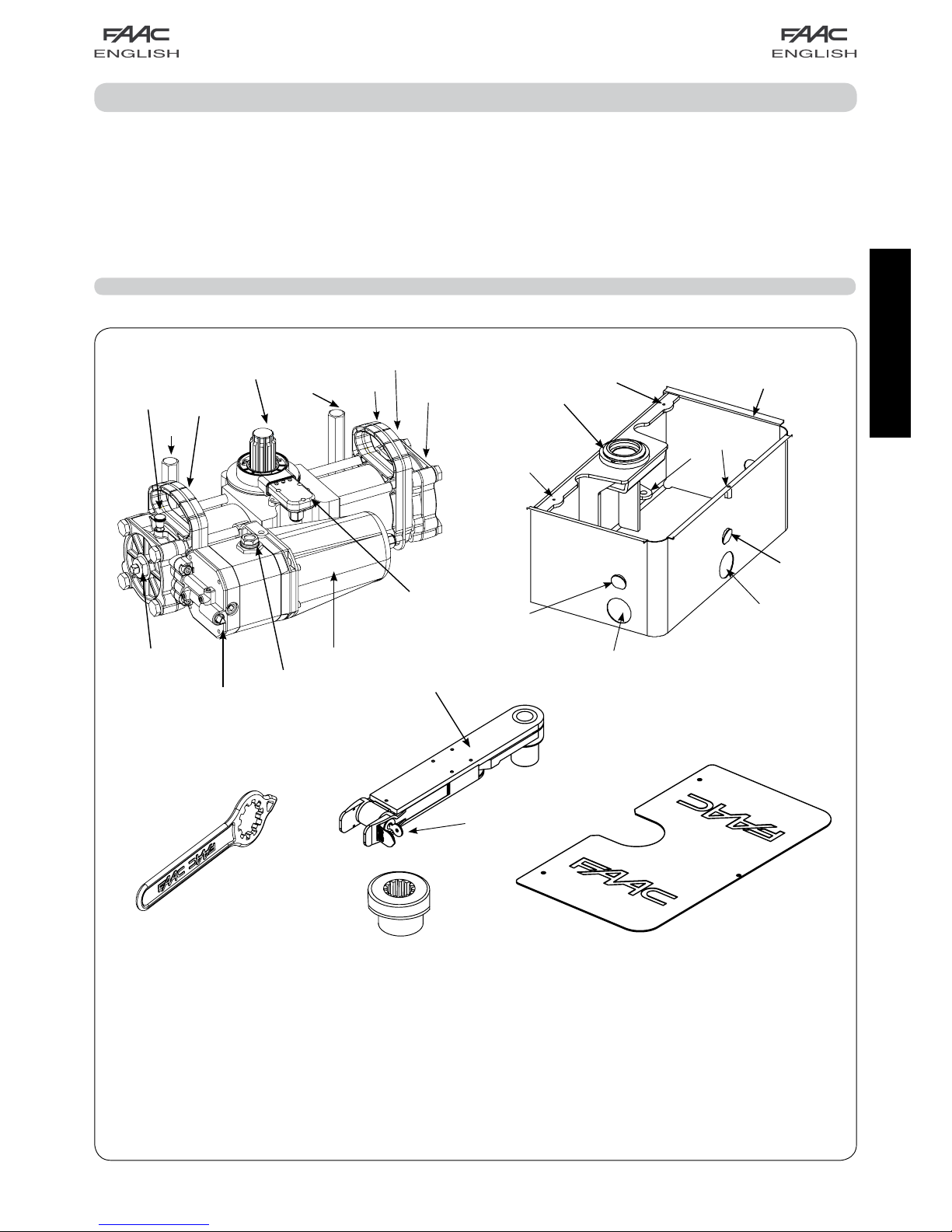
Fig.1
a Bleed screw
b Support handle
c Pinion
d Securing screws
e Screw for adjusting travel-limit mechanical stops
f Hydraulic release
g Oil filling plug
h Motor
i Electronic encoder
j Bearing case
k Holes for securing the cover
l Slots for securing the jack
m Bearing bush
n Gate support bracket
o Key-operated release device
p Wings for walling the bearing case.
q Hole for power cable or drain pipe
r Release and adjustment key
s Closing cover
t Grooved bush
Page 4

270
480
229
480
270
22
22
4
3
5
1
1
249
ENGLISH
4
3 DIMENSIONS
4 ELECTRICAL PREPARATIONS
Fig.2
Fig.4
5.2 WALLING IN THE BEARING CASE
These are the possible work conditions:
a) Existing gate with fixed hinges.
b) Existing gate with adjustable hinges.
c) Gate to be made.
5 INSTALLING THE AUTOMATED SYSTEM
5.1 PRELIMINARY CHECKS
To ensure a correctly operating automated system, the structure
of the existing gate or gate to be built must satisfy the following
requirements:
1) Individual leaves must not weight more than 800 kg.
2) Maximum length of single gate: 2 mt CBAC, 4 mt SB
3) A strong and rigid leaf structure.
4) Smooth, uniform gate movement, without any irregular friction
during the entire travel.
5) Distance “A” between lower edge of gate and ground as
shown in Fig. 7.
6) The distance between the gate leaves - in the opening and
closing positions - and the existing structures, must respect
current legal regulations
We advise you to carry out the metalwork jobs before installing
the automated system.
The condition of the structure directly influences the reliability and
safety of the automated system.
3.1 STANDARD VERSION
TECHNICAL
SPECIFICATIONS
CBAC
OPERATOR
SB
OPERATOR
Power supply (V dc) 24
Absorbed power (W) 60 (*)
Protection class IP 67
Type of oil FAAC HP OIL
Operating ambient temperature
-20° C +55°C
Rated Operating Time (R.O.T.) Continous duty at 55°C
Hydraulic shut-down facility Supplied Not supplied
Pump flow-rate (lpm) 0.36
Max. torque (Nm)
**
500 (E700) ; 600 (E124)
Angular speed (°/sec) *** 5.5 (E700) ; 8.2 (E124)
Max opening angle **** 113° (S700H 100°)
187° (S700H 180°)
Leaf max. length (m) 2 4
Leaf max. weight (Kg) 800
2 TECHNICAL SPECIFICATIONS
NOTE: ALL MEASUREMENTS IN MILLIMETRES.
TO ENSURE CORRECT INSTALLATION, THE LEAF ROTATION
AXIS MUST BE PERFECTLY ALIGNED WITH THE OPERATOR
(Fig. 7)
Fig.3
3.2 VERSION WITH MECHANICAL RELEASE
* EACH INDIVIDUAL OPERATOR
** CONSIDERING 55 Bar OF STATIC PRESSURE IN THE CHAMBERS
*** CONSIDERING A PUMP CAPACITY OF 0.6 Ipm
**** 3° OF TRAVEL ARE LOST WHILE THE OPERATOR IS BEING
INSTALLED
a S700H Operators with encoder
2x2.5 mm ² / AVG 12 for motor (minimum)
2x0.5 mm ² / AVG 20 for encoder bus
b Bus 2 Easy Photocells
2x0.5 mm ² / AVG 20
c Control unit
(To be selected according to the installed power supply)
2x2.5 mm ² / AVG 12 for powering
d Key operated push-button
2x0.5 mm ² / AVG 20
e Flashing lamp 24 V
2x1.5 mm ² / AVG 16
230 V ~ / 50 Hz
or
115 v ~ / 60Hz
(According to
the selected
control unit)
To avo id exce ssi ve volt age dro ps , we reco m-
mend that the length of the motor cables with
a section of 2.5 mm, should not exceed 20 m.
The maximum total length of the BUS cables must not
exceed 100 m.
Page 5

min 40
min. 10
min. 250
57
A
580
290
290
290
a
a
A
B
90°90°
ENGLISH
5
2) Position the bearing case level, respecting the indications in
figure 7.
The centre of the hole on the case must be perfectly aligned
with respect to the leaf rotation axis.
Take a PVC tube with 16 mm diameter to route the power cable.
Insert it in the hole on the bearing case (Fig.1 ref.q) and take it
to the electronic control unit. (See figure 8)
Provide a 50 diameter drain pipe, for rain water, so that it arrives
at the nearest sewage channel (fig.8).
4) Wall the bearing case in the foundation pit.
Fig.7
5.3 FITTING THE GATE
NOTE: Before you do this job, wait for the cement
in the foundation pit to set.
Fig.9
5.3.1 OPERATOR CBAC-SB
1) Dig a foundation pit as shown in Fig. 6.
Fig.6
NOTE: 1) To avoid the pit surface sinking, we advise
you, according to the soil, to make a preparatory
bottom over which to pour quick-setting cement.
2) Fit a rain water drain pipe on the
bearing case, reaching the nearest sewer, as shown
in Fig. 8 for example
LEAF ROTATION AXIS
LEAF ROTATION AXIS
1) Make the gate guide bracket, with a “U” profile with dimensions
as in figure 9.
Fig.5
GUIDE
BRACKET
DRAIN
PIPE
Fig.8
1) Decide on the correct position of the bush, referring to the
position of the leaf with respect to the rotation axis, as shown in
Fig. 10-11
TUBE IN PVC FOR
OPERATOR POWER
CABLE
CONTROL
UNIT
“A” MEASUREMENT (mm)
Without
mechanical
release
With
mechanical
release
26 47
LEAF ROTATION
AXIS
GUIDE BRACKET MID-POINT
NOTE: To exploit the operator’s entire rotation, the
bearing case must be installed perpendicularly with
respect to the closed position of the gate - as shown
in Fig. 5.
Fig.10
Page 6

a
a
ENGLISH
6
2) Determine the position of the guide bracket on the support
bracket, referring to the leaf rotation axis, as shown in Fig. 15.
3) Accurately weld the guide bracket on the support bracket as
shown in Fig. 15, so that the mid-points of the two brackets are
aligned with each other.
LEAF ROTATION AXIS
Fig.15
4) Insert the gate in the guide bracket and hinge it.
5) Close the guide bracket, from the pilaster side, welding a plate
as shown in Fig. 15 ref.a.
6) Manually check if the gate is free to open and close completely,
stopping on the travel-limit mechanical stops, if supplied, and if
leaf movement is smooth and friction- free.
MID-POINT
5.3.2 OPERATOR CBAC-SB WITH MECHANICAL RELEASE
Fig.12
2) Accurately weld the bush on the profile (Fig.12) so that the
notch on the bush corresponds to the profile mid-point, as shown
in Fig. 11.
3) Fit the guide bracket on the bearing case.
Fig.13
To avoid comprom is in g goo d ope ra tion of the
automated system, do not, on any account, weld
the gate leaf on the guide bracket or on the support
bracket.
4) Insert the gate in the guide bracket and hinge it.
5) Close the guide bracket, from the pilaster side, welding a plate
as shown in Fig. 10 ref.a.
6) Manually check if the gate is free to open and close completely,
stopping on the travel-limit mechanical stops, if supplied, and if
leaf movement is smooth and friction- free.
GUIDE
BRACKET
SUPPORT BRACKET
LEAF ROTATION AXIS
Fig.11
1) Insert the support bracket (Fig.1 ref. n) on the bearing case.
Fig.14
GUIDE BRACKET
MID-POINT
LEAF ROTATION AXIS
SUPPORT
BRACKET
GUIDE
BRACKET
SUPPORT BRACKET
NOTCH
TYPE 1
TYPE 2
Page 7

a
b
a
A
B
90
90
0
90
90
0
90
90
0
a
a
A B
ENGLISH
7
TRAVEL-LIMIT STOP
AT OPENING
TRAVEL-LIMIT STOP AT CLOSING
Fig.16
Fig.18
5.4 INSTALLING THE OPERATOR
Fig.17
SECURING SCREWS
5.4.1 OPERATOR WITHOUT MECHANICAL EMERGENCY RELEASE
1) Take the gate to its open position.
2) Consulting the instructions in chapter 8.1, hydraulically release
the operator, using the key (Fig. 1 ref.r) on the release screw
(Fig. 1 ref.f)
3) On the operator, unscrew the plug (Fig.16 ref. A) of the screw
of the closing travel limit device (Fig. 16 ref. a).
4) Back off the closing travel limit screw (Fig.16 ref. B) by
one turn (IMPORTANT FOR CORRECT COUPLING OF THE
PINION-GROOVED BUSH DURING INSTALLATION).
5) Turn the operator pinion with the supplied wrench (Fig. 1
ref. r), in the gate closing direction as shown in Fig. 16, up to
the internal stop point of the piston, and remove the key.
8) Using the handles, insert the operator in the bearing case as
shown in Fig. 18 A,
9) Close the gate.
10) Raise the operator with its handles (Fig. 18 ref. B), inserting
the pinion in the grooved bush of the bearing case. To facilitate
the operation, slightly rotate the operator until coupling takes
place.
11) Insert and screw the fastening screws with groover and washer
as shown in Fig. 18 B ref. a, in order to secure the operator to
the bearing case. (TO FACILITATE THE OPERATION, SUPPORT THE
MOTOR FROM THE CENTRAL PART)
12) Open the gate and check if the opening travel-limit stop
is correctly positioned; if necessary, adjust the travel-limit stop,
referring to the instructions in chapter 6.
13) Close the gate and check if the closing travel-limit stop is
correctly positioned; if necessary, adjust the travel-limit stop,
referring to the instructions in chapter 6.
14) Hydraulically shut down the operator as per instructions in
chapter 8.1.
15) As described in the instructions for the control board, make
the electrical connections, taking care over encoder polarity.
16) Secure the cover of the bearing case with the supplied
screws.
6) Without moving the pinion, insert the supplied wrench on the
operator as shown in Fig. 17, and make sure that it indicates 0
(ZERO) on the operator’s plastic panel (Fig. 17 ref.a). If necessary
rotate the pinion with this. (IMPORTANT FOR CORRECT COUPLING
OF THE PINION-GROOVED BUSH DURING INSTALLATION).
NOTE: if necessary, lightly screw the closing travel-limit screw
7) Remove the adjustment wrench, screw the plug of the travel
limit screw and grease the pinion.
IMPORTANT: REMOVE THE ENCODER BEFORE YOU
BEGIN MECHANICAL INSTALLATION
Page 8

a
b
A B
a
90°
ENGLISH
8
6 POSITIVE STOP - (INTERNAL MECHANICAL TRAVEL-LIMIT STOPS)
The S700H operator is supplied standard with internal opening
and closing mechanical stops. This is to facilitate the installation
operations because there is no need to construct the mechanical
stop elements.
The mechanical travel-limit stops (POSITIVE STOP) can be adjusted
in the last 30° of the operator’s MAXIMUM travel, at both opening
and closing.
FAAC SUPPLIES THE TRAVEL LIMIT DEVICES TOTALLY OPEN ( MAXIMUM
PINION ROTATION ANGLE ) ,
6.1 ADJUSTMENT OF THE TRAVEL-LIMIT STOPS
TRAVEL-LIMIT STOP
AT OPENING
TRAVEL-LIMIT STOP AT CLOSING
Fig.20
1) Hydraulically release the operator. (See chpt 8.1)
2) Close the leaf, manually taking it into its closed position.
3)
Unscrew the cap (Fig. 20 ref.A) of the closing travel-limit screw
(Fig. 20 ref.a)
CLOSING POSITION
OPENING POSITION
Fig.19
1) Take the gate to its open position.
2) Consulting the instructions in chapter 8.1, hydraulically release
the operator, using the key (Fig. 1 ref. r ) on the release screw
(Fig. 1 ref. f)
3) On the operator, unscrew the cap (Fig. 16 ref.A) of the closing
travel-limit screw (Fig. 16 ref. a).
4) Unscrew the closing travel-limit (Fig. 16 ref.A) screw by
one turn (IMPORTANT FOR CORRECT COUPLING OF THE
PINION-MECHANICAL RELEASE DURING INSTALLATION).
5) Turn the operator pinion with the supplied key (Fig. 1 ref. r), in
the gate closing direction as shown in Fig. 16, up to the internal
stop point of the piston, and remove the key.
6) Without moving the pinion, insert the supplied key on the
operator as shown in Fig. 17, and make sure that it indicates 0
(ZERO) on the operator’s plastic panel (Fig. 17 ref.a). If necessary
rotate the pinion with this.
( I M PO R T A N T F O R C O R RE C T C O U PL I N G OF T H E
PINION-MECHANICAL RELEASE DURING INSTALLATION).
NOTE: if necessary, lightly screw the closing travel-limit screw
7) Remove the adjustment key
8) Lightly grease the operator pinion.
9) Using the handles, insert the operator in the bearing case as
shown in Fig. 18 A
10) Take the gate to its CLOSED position.
11) Free the mechanical release, referring to paragraph 8.2.
12) Take the released gate into open position, making sure that
the released part freed from the gate remains in the gate closed
position as shown in Fig.
19 ref. a.
13) Raise the operator with its handles (Fig. 18 ref. B), inserting the
pinion in the grooved bush in the bearing case. If it does not enter,
slightly rotate the operator until coupling takes place.
14) Insert and screw the fastening screws with groover and washer
as shown in Fig. 18 B ref. a, in order to secure the operator to the
bearing case (TO FACILITATE THE OPERATION, SUPPORT THE MOTOR
FROM BENEATH THE CENTRAL PART).
15) Close the gate and re-lock it to the mechanical release.
16) Open and close the gate, checking and, if necessary,
adjusting the respective travel limit devices as described in
chapter 6.1.
17) As described in the instructions for the control unit, make the
electrical connections, taking care over encoder polarity.
18) Hydraulically shut down the operator as per instructions in
chapter 8.1.
5.4.2 OPERATOR WITH MECHANICAL RELEASE
Page 9

a
a
b
c
b
a
ENGLISH
9
BEFORE CARRYING OUT THE RELEASE AND SHUT-DOWN
OPERATIONS, MAKE SURE THAT YOU HAVE CUT POWER
TO THE OPERATOR AND THAT IT IS NOT MOVING
8 MANUAL OPERATION
8.1 HYDRAULIC RELEASE OF THE OPERATOR
If the gate has to be moved manually due to a power cut or
fault of the automated system, use the hydraulic release device
with the release key (Fig.21 ref. b):
1) Remove the cover from the bearing case.
2) Turn the release screw (Fig.21 ref.a) inserting the triangular
recess of the supplied key (Fig.21 ref. b):
- To RELEA SE, turn the screw anti-clockwise by at least one
turn. (DO NOT COMPLETELY UNFASTEN THE SCREW TO AVOID OIL
COMING OUT.
- To SHUT-DOWN again, turn the screw clockwise up to the
mechanical stop point.
Fig.21
8.2 MECHANICAL EMERGENCY RELEASE (OPTIONAL)
For the S700H operator, a manual mechanical emergency
release is available as an optional item.
If the gate has to be moved manually due to a power cut or fault
of the automated system, use the release key device.
The device is inserted on the gate support bracket (fig. 22 ref.
a) and enables you to release the system from both inside and
outside the premises.
SUPPORT BRACKET
RELEASE KEY
RELEASE LEVER
Fig.22
Fig.23
PROTECTIVE
HATCH
RELEASE KEY
RELEASE LEVER
Procedure for manual leaf operation:
1) Open the protective hatch (Fig.23 ref. b).
2) Insert the release key in the lock (Fig. 23 ref. c) and turn it
clock-wise sense up to its stop point.
3) Pull the release lever toward you (Fig. 23 ref. a).
4) Move the leaf by hand.
Procedure for restoring the system to normal operation:
1) Move the release lever back to its rest position (Fig.22)
2) Insert the release key in the lock (Fig.23 ref.c), turn it in the
opposite direction up to the stop point and remove it.
3) Close the protective plug of the lock.
4) Move the leaf manually until it hooks on the shut-down
bracket.
RELEASE KEY
RELEASE SCREW
7 FINAL OPERATIONS
1) Place the encoder in its seat on the motor.
2) Connect the motor (Fig.1 ref. h) and the encoder (Fig.1
ref. i) to the control unit, following the specific instructions.
3) Secure the cover of the bearing case with the supplied
screws.
4) Where specified by current legal regulations, place at least
two signs with the words “Danger: Automatic motion” on both
sides of the automated system.
To avoid excessive voltage drops, we recommend
th a t t h e leng t h o f the mo t o r cable s w i t h a
se cti o n of 2.5 mm , sho uld not ex cee d 20 m.
The maximum total length of the BUS cables must not
exceed 100 m.
4) Unscrew the travel-limit stop screw (Fig. 20 ref.B) at closing
(Fig.20 ref.a), until the leaf begins to move.
5) Fasten the lock-nut of the travel-limit stop screw.
6) Open the leaf, manually taking it into its opening position.
7) CREW the cap of the screw of the opening travel-limit stop
(Fig.20 ref.b).
8) UNSCREW the travel-limit stop screw (Fig.20 ref. b), until the
leaf begins to move.
9) CREW the cap of the travel-limit stop screw.
10) Open and close the gate to check if the travel-limit stop is
correctly adjusted.
11) Shut-down the operator again, following the instructions in
chapter 7.1.
Page 10

b
a
ENGLISH
10
9.1 OIL LEVEL CHECK
Check oil level periodically by unscrewing the filling plug (Fig.1
ref.g), check if the oil is just below the plug and, if necessary,
top up.
Topping-up operations must be done only with FAAC HP OIL.
OPENING BLEED
SCREW
CLOSING BLEED
SCREW
Fig.24
The presence of air in the hydraulic circuit causes the automated
system to operate incorrectly, i.e. a faulty movement of the leaf
and too much noise while operating.
Procedure to avoid this problem:
1) Command the gate to open.
2) While the leaf is moving, loosen the opening bleed screw
(Fig.24 ref.a)
3) Using the bleed screw, allow the air to come out from the
hydraulic circuit until non-emulsified oil appears.
4) Tighten the bleed screw before the operator finishes the
opening cycle.
5) Command the gate to close.
6) While the leaf is moving, loosen the closing bleed screw
(Fig.24 ref.b)
7) Using the bleed screw, allow the air to come out from the
hydraulic circuit until non-emulsified oil appears.
8) Tighten the bleed screw before the operator finishes the
closing cycle.
9) Repeat these operations several times.
10) Top up oil level, referring to the instructions in this chapter.
9.2 BLEEDING OPERATIONS
THE S700H OPERATOR IS SUPPLIED WITH THE HYDRAULIC
CIRCUIT ALREADY AIR FREE. DO NOT BLEED. BLEEDING
IS ONLY NECESSARY IN THE EVENT OF MAINTENANCE OF
THE HYDRAULIC SYSTEM OR TOPPING-UP OIL LEVEL.
9 MAINTENANCE
Run a functional check of the system at least every 6 months,
with special attention to the efficiency of the safety and release
devices (including the thrust force of the operator), and to perfect
operation of the gate hinges.
Also, periodically check quantity of oil inside the tank.
The safety devices installed on the system must be checked
every 6 months.
 Loading...