

Page 1
S450H
Page 2
EC DECLARATION OF CONFORMITY FOR MACHINES
(DIRECTIVE 2006/42/EC)
Manufacturer: FAAC S.p.A.
Address: Via Calari, 10 - 40069 Zola Predosa BOLOGNA - ITALY
Declares that: Operator mod. S450H
is built to be integrated into a machine or to be assembled with other machinery to create a machine under the provisions
of Directive 2006/42/EC
complies with the essential safety requirements of the following EEC directives:
2006/95/EC Low Voltage Directive
2004/108/EC Electromagnetic Compatibility Directive
It further declares that it is not allowed to put the device in operation until the machine it has to be integrated into or of which it is going
ENGLISH
to become an integral part has been identified and its conformity has been declared under the provisions of the Directive 2006/42/EEC
and subsequent amendments.
Bologna, 01.02.10
The Managing Director
A. Marcellan
IMPORTANT INSTRUCTIONS
FOR THE INSTALLER GENERAL SAFETY
1) ATTENTION! To ensure personal safety, carefully read following instruc-
tions. Improper installation or misuse of the product can cause serious
personal injuries.
2) Carefully read the instructions before installing the product.
3) Packaging material (plastic, polystyrene, etc.) is a potential hazard and
must be kept out of reach of children.
4) Keep these instructions for future reference.
5) This product was designed and manufactured exclusively for the purpose
indicated in this documentation. Any other use, not expressly indicated
here, could compromise the good condition/operation of the product
and/or be a source of danger.
6) FAAC declines any responsibility for improper use or use other than that
for which the automated system was intended.
7) Do not install the equipment in an explosive atmosphere: the presence
of inflammable gas or fumes is a serious danger to safety.
8) Mechanical constructive elements must comply with the requirements
of the EN 12604 and EN 12605 standards.
In addition to their national legal regulations, countries outside the EC
must follow the above mentioned standards in order to guarantee an
adequate level of safety.
9) FAAC cannot be held responsible for failure to observe technical stand
ards in the construction of the closing elements to be motorised nor for
any deformation which may occur during use.
10) The installation must be carried out in conformity with the EN 12453 and
EN 12445 standards.
In addition to their national legal regulations, countries outside the EC
must follow the above mentioned standards in order to guarantee an
adequate level of safety.
11) Disconnect the power supply before any operation on the system.
12) The power mains of the automated system must be fitted with a multi-pole
power switch with a switch-contact gap of at least 3 mm. The use of a 6A thermomagnetic switch with multi-pole switching is recommended.
13) Make sure that a differential switch with trip threshold of 0.03 A is fitted
upstream of the system.
14) Make sure that the earthing system is at the state of art and connect
it to the metallic parts of the closing system.
15) The automated system is equipped with an intrinsic anti-crushing safety
device of the torque control type. Its tripping threshold must be verified
according to the requirements specified in the Standards listed in 10.
16) The safety devices (EN 12978) protect from the hazards caused by
mechanical movements, such as crushing, entrapment and shearing
hazards.
17) Each installation should be fitted with at least one flashing light (e.g.
FAACLIGHT) and a warning sign suitably secured to the frame structure,
in addition to the devices described in 16 above.
18) FAAC declines any responsibility regarding safety and efficient opera
tion of the automated system if parts other than FAAC original parts
are used.
19) Use only FAAC original parts for maintenance.
20) Do not in any way modify the automated system components.
21) The installer shall provide all information concerning the manual opera
tion of the system in the event of an emergency and shall hand over
to the end-user the warning instructions supplied with the product.
22) Keep children, adults or objects away from the product while it is op
-
erating.
23) Keep remote controls or other pulse generators out of reach of children,
to prevent the automated system from being activated unintention
ally.
24) Transit is permitted only when the automated system is non in opera
tion.
25) The automated system cannot be repaired/adjusted by the end-user;
these operations can only be carried out by qualified personnel.
26) Maintenance: the functional check of the system must be carried out
at least every six months; pay special attention to the good working
condition of the release and safety devices (including, where foreseen,
the thrust force of the operator).
27) Feed the automation system only when explicitly stated.
28) Anything not expressly specified in these instructions is not permitted.
-
-
-
-
-
1
Page 3
2
1
1
2
2
2
5
3
4
6
6
RX
RX
TX
TX
7
S450H
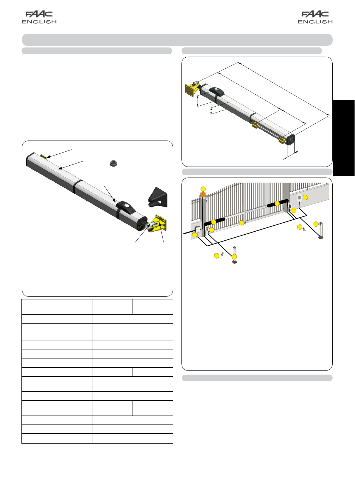
1 DESCRIPTION AND TECHNICAL SPECIFICATIONS
The FAAC S450H automated system for swing-leaf gates consists
of an electrical pump and an hydraulic piston transmitting the
leaf movement, assembled in a single block.
The model with hydraulic lock can automate leaves up to 2 m.
It does not require the installation of electric locks and guaran
tees that the leaf is mechanically locked when the motor is not
in operation. The model without hydraulic lock always needs
one or more electric locks to guarantee the leaf mechanical
lock. The S450H automated systems have been designed
and built to automate swing-leaf gates. Avoid any other use
whatever.
1.1 DIMENSIONS
-
119
85
750
1113
311
a
b
g
c
d
a Front fitting
b Cover
c Emergency release with key
d Plastic cover for rear bracket
e Rear bracket
f Encoder
g Spacer for opening mechanical stop
TECHNICAL
SPECIFICATIONS
CBAC
OPERATOR
Power supply (V dc) 24 - 36
Power consumption (W) 70 (nominal) - 288 (maximum)
Protection class IP 55
Oil type FAAC HP OIL
Operating temperature -20°C +50°C
Rated Operating Time (R.O.T.) Continuos duty at 55°C
Hydraulic lock Installed Not installed
Traction/thrust force
5000 (E124) - 3600 (E024S)
max (N)
Max. opening angle See table 1
Max. leaf length (m) 2 3
Rod linear speed (Cm/s) 2,5 (E124) - 2,0 (E024S)
Effective rod stroke (mm) 311
Operator weight (kg) 10.8
* CONSIDERING 40 bar (E124) 30 bar (E024) STATIC PRESSURE
ON PISTONE
** CONSIDERING A RANGE OF PUMP 1.5 lpm (E124) AND 1.2
lpm (E024S)
f
OPERATOR
SB
e
Fig. 1
Dimensions in millimeters
85
Fig. 2
2 PRESETTINGS
a S450H operators (2x2.5 mm² each motor)
(2x0.5 mm² each encoder bus)
b RX Photocells (receiver)
(TRADITIONAL: 4 x 0.5
mm²; 2easy bus: 2 x 0.5 mm²)
b TX Photocells (transmitter) (2 x 0.5 mm²)
c Electronic control unit
(power supply 3 x 1.5
mm²)
d Key-operated push-button (e.g. T11) (3 x 0.5 mm²)
e Flashing lamp 24 V dc (2 x 1 mm²)
f Opening mechanical stops*
g Electric lock and closing mechanical stop
(2 x 1.5 mm)
* Not necessary in case of use of opening mechanical stops
inside the operator (Fig.1 re.g)
Fig. 3
3 INSTALLATION OF THE AUTOMATED SYSTEM
Following conditions have to be met to ensure safety and the
efficient operation of the automated system:
• The gate structure must be suitable for automation. Verify in
particular that it is sufficiently strong and stiff and that dimensions and weight correspond to those stated in the technical
specifications.
• Verify the smooth and uniform movement of leaves, without
irregular friction during the whole travel.
• Verify the good condition of hinges.
• Verify the presence of mechanical limit switches.
• Remove any locks and bolts.
Carry out any metalwork operations before installing the automated system.
ENGLISH
2
Page 4

- If the gate structure does not allow the stable fixing of the front fitting, create a firm bearing surface in the leaf structure.
- It is advisable to grease all fixing pins - Opening and closing stops must always be installed - Play special attention not to
damage the operator rod
3.2 INSTALLATION DIMENSIONS (Dimensions in millimeters)
ATTENTION: do not cut for any reason the rear bracket
Make reference to figures 4 and 5 and to table 1 to determine the installation position of the operator.
B
Dimensions in millimeters
85
1060
D
ENGLISH
50
75
Z
100
Fig. 4
a
Fig. 5
Dimensions in millimeters
INSTALLATION
DIMENSION
"D"
(SEE FIGURE 5)
- INTERSECT THE DIMENSIONS "D" AND "B" TO OBTAIN THE MAXIMUM VALUE OF OPENING GRADES.
- ATTENTION: USE MECHANICAL LIMIT SWITCHES IN ORDER NOT TO EXCEED THE MAXIMUM OPENING GRADES STATED IN TABLE 1 AND GUARANTEE
THE CORRECT OPERATION OF THE AUTOMATED SYSTEM.
TAB. 1
20-24 110° (3) 110° (3) 115° (3) 108° (3) 100° (3) 100° (3)
25-34
35-44
45-54 100° (3) 105° (3) 106° (3) 100° (3) 106° (2) 100° (2) 96° (2)
55-64 97° (3) 100° (3) 105° (3) 99° (3) 107° (2) 100° (2) 96° (2) 92° (2)
65-74 93° (3) 97° (3) 100° (3) 100° (3) 110° (2) 101° (2) 96° (2) 102° (1) 98° (1)
75-84 90° (3) 95° (3) 100° (3) 105° (2) 102° (2) 111° (1) 105° (1) 98° (1) 94° (1)
D
85-94 90° (3) 90° (3) 95° (3) 100° (2) 104° (2) 96° (2) 104° (1) 100° (1) 94° (1) 90° (1)
95-104
105-114
115-124
125-134
135-144
145-154
155-164
165-170
D
75-84 85-94 95-104 105-114 115-124 125-134 135-144 145-154 155-164 165-175
90° (3) 90° (3) 95° (3) 100° (2) 96° (2) 106° (1) 98° (1) 96° (1) 90° (1)
90° (3) 90° (3) 95° (2) 97° (2) 103° (1) 99° (1) 94° (1) 92° (1)
90° (3) 90° (2) 95° (2) 98° (1) 100° (1) 94° (1)
90° (2) 90° (2) 95° (1) 98° (1) 94° (1)
90° (2) 90° (2) 95° (1) 94° (1)
90° (1) 90° (1) 94° (1)
90° (1) 90° (1)
90° (1)
INSTALLATION DIMENSION "B"
(SEE FIGURE 4-5)
TAB.1
XXX 120° (3) 120° (3)
XXX 110° (2) 110° (2)
XXX 115° (1) 110° (1)
B
XXX XXXX
100° (3) 107° (3) 108° (3) 104° (3) 111° (2) 104° (2) 100° (2)
a° (3)
a° (2)
a° (1)
(3)
HOLE TO BE USED
ON THE REAR
BRACKET
(2)
(1)
B
108° (3) 110° (3) 110° (3) 103° (3) 100° (3) 94° (3)
HOLE TO BE USED ON THE REAR BRACKET
3
Page 5

3.3 INSTALLATION OF OPERATORS
Check the perfect level then weld the rear fitting to the pil-
1.
lar or fix it by means of suitable screws, dowels / threaded
inserts. Observe the dimensions stated in Tab.1 (never cut
the rear fitting; moreover it must be installed with the word
"UP" facing up as shown in figure 6 re.
a).
INSTALL THE BRACKET
WITH THE WORD “UP”
FACING UP
a
Install the encoder on the rear bracket by correctly engag-
3.
ing it on the pin then fix it with the screw and nut supplied
(Fig. 8 re. a b c).
Slightly press the protection cover on the rear bracket to
4.
install it (Fig. 9).
Assemble the operator and the rear bracket by means of
5.
the pin and nut supplied (Fig. 10 re. a - b).
HOLE FOR
ENCODER
CABLE
ROUTING
ENGLISH
Fig. 9
By means of table 1 (see white or grey boxes) choose the
2.
fixing hole on the rear bracket and install the fork (Fig. 7
re.
a) by assembling it with the special pin supplied (Fig. 7
re.
b).
xx°(1)
b
xx°(2)
a
b
xx°(3)
Fig. 6
Fig. 7
a
b
Screw one-half of the thread of the front articulated joint on
6.
the operator rod and tighten the nut (Fig. 11 re. a).
Unlock the operator according chapter 4.
7.
If no external mechanical stop point at closure is present,
8.
you may use the stop point inside the operator. Therefore
remove the rod completely up to its internal stop point.
If an external mechanical stop point at closure is present,
9.
remove the rod completely and then insert it 5 mm.
b
a
Fig. 10
a
c
Fig. 8
Fig. 11
4
Page 6

ENGLISH
If an external mechanical
stop point at closure is pre-
sent, remove the rod completely and then insert it 5 mm.
Fig. 12
Secure the operator to the front fixing (Fig. 15).
15.
Remove the bleed screw (Fig.16 ref. a) paying special
16.
attention to leave the sealing O-Ring in its seat
Install the metallic protection cover as shown in Fig. 16, insert
17.
and tighten both tie-rods
Connect the cable to the operator using the two screws
18.
supplied, as shown in Fig. 17.
Fig. 14
Close the gate leaf and install the front fitting on the rod as
10.
shown in Fig. 11 re.
Establish the fixing position of the front fitting on the leaf
11.
and mark the fixing points (Fig. 12)
perfectly level).
Disassemble the operator from the front fixing to avoid dam-
12.
aging the rod when the front fixing is installed on the gate.
Weld the front fixing directly on the leaf or screw it by means
13.
of threaded inserts.
If an opening mechanical stop on ground is not installed,
14.
spacers can be used (Fig. 1 re.
ticulated joint and insert on the rod the number of spacers
required to reach the desired opening angle (Fig. 14).
b.
(the operator must be
g). Remove the front ar-
Fig. 15
a
Fig. 16
Fig. 13
MINIMUM
BENDING
RADIUS
60 mm
5
MINIMUM
BENDING
RADIUS
60 mm
Fig. 17
Page 7

4 MANUAL OPERATION
The models S450H SB are not equipped with a release facility since, thanks to the particular configuration of the hydraulic
distributing flange, you do not need to release the operator to manually move the leaf
If the gate is to be operated manually because of a power failure or an automated system fault, activate the release device.
1) Lift the protection lid (Fig. 18, re.
2) Turn the key 90° clockwise to open the cover and lift it.
3) Turn the release knob (Fig. 18, re. c
4) Open or close the leaf manually.
To restore the normal operation of the automated system, perform the above described operations in reverse order.
a) and insert the key in the lock (Fig. 18, re. b).
) anticlockwise until it stops.
CLOSED
a
b
OPEN
5 ELECTRICAL CONNECTION OF THE "2easy bus" ENCODER
The S450H operator is fitted with an encoder system with "2easy bus" technology. The proper assignment of the leaf to the corresponding encoder depends on the connection of the two encoder wires (leaf 1- encoder 1; leaf 2 - encoder 2).
THE ENCODER WIRES MUST BE CONNECTED TO THE "2easy bus" CONNECTOR OF THE ELECTRONIC EQUIPMENT.
To verify the proper combination LEAF 1 - ENCODER 1 - MOTOR 1 and LEAF 2 - ENCODER 2 - MOTOR 2, refer to the LEDs on the
encoders, as shown by table 2 and the figures 19 - 20 - 21.
To invert the leaf-encoder combination, change the encoder polarity by swapping its wires until the right LEDs are lit.
The LEDs of the encoder remain visible also with the protection cover of the rear
bracket installed.
UNLOCKED
c
LOCKED
Fig. 18
ENGLISH
DL 1: must always be ON to ensure the right connection between encoder and board.
DL 2: indicates the leaf where the encoder is installed.
If the encoder is installed on leaf 1, the DL 2 LED is ON.
If the encoder is installed on leaf 2, the DL 2 LED is OFF.
when blinking at regular intervals, it signals the pulse reading during the leaf
DL 3:
movement. When the gate leaf is stationary, DL 3 is OFF.
TABLE 2
LED ON BLINKING OFF
DL 1
Power supply ON and BUS - board
communication
Power supply ON but
no BUS communication
(e.g.: cabling fault)
Power supply OFF and no BUS communi-
cation
(e.g.: missing or broken connection)
DL 2 Encoder associated to leaf 1 / Encoder associated to leaf 2
DL 3
/ Pulse reading during leaf movement Leaf stationary
6
Page 8

DL 2
DL 1
DL 3
DL 2
DL 1
DL 3
DL 2
DL 1
DL 3
DL 2
DL 1
DL 3
Fig. 19
ENGLISH
LEAF 1*
THROUGH THE BRACKET COVER OF LEAF
1, VERIFY THAT THE LEDS DL1 AND DL2
ARE ON WHEN THE MOTOR IS NOT IN
OPERATION
LEAF 1
TWO LEDS ON
LEAF 2
THROUGH THE BRACKET COVER OF LEAF
2, VERIFY THAT THE LED DL1 IS ON WHEN
THE MOTOR IS NOT IN OPERATION
LEAF 2
THROUGH THE BRACKET COVER OF LEAF
2, VERIFY THAT THE LED DL1 IS ON WHEN
THE MOTOR IS NOT IN OPERATION
LEAF 2
ONE LED ON
Fig. 20
LEAF 1*
THROUGH THE BRACKET COVER OF LEAF
1, VERIFY THAT THE LEDS DL1 AND DL2
ARE ON WHEN THE MOTOR IS NOT IN
OPERATION
LEAF 2
ONE LED ON
*
LEAF 1 OPENS FIRST AND CLOSES AFTER LEAF 2.
IF LEAF 1 AND LEAF 2 DO NOT OVERLAP, ON THE
ELECTRONIC CONTROL BOARD, IF AVAILABLE, THE
LEAF DELAY CAN BE SET TO ZERO.
BY SWAPPING THE ENCODER WIRES, THE ENCODER
ASSOCIATED TO LEAF 1 CAN BE COUPLED TO LEAF
2 AND VICE VERSA (see example Fig. 22)
ENCODER WIRES
SWAPPING
ENCODER
LEAF 1
7
LEAF 1
TWO LEDS ON
Fig. 21
ENCODER
LEAF 2
Fig. 22
Page 9

Le descrizioni e le illustrazioni del presente manuale non sono impegnative. La FAAC si riserva il diritto, lasciando inalterate le caratteristiche essenziali dell’apparecchiatura, di apportare in qualunque momento e senza impegnarsi
ad aggiornare la presente pubblicazione, le modifiche che essa ritiene convenienti per miglioramenti tecnici o per
qualsiasi altra esigenza di carattere costruttivo o commerciale.
The descriptions and illustrations contained in the present manual are not binding. FAAC reserves the right, whilst
leaving the main features of the equipments unaltered, to undertake any modifications it holds necessary for either
technical or commercial reasons, at any time and without revising the present publication.
Les descriptions et les illustrations du présent manuel sont fournies à titre indicatif. FAAC se réserve le droit d’apporter à
tout moment les modifications qu’elle jugera utiles sur ce produit tout en conservant les caractéristiques essentielles,
sans devoir pour autant mettre à jour cette publication.
Die Beschreibungen und Abbildungen in vorliegendem Handbuch sind unverbindlich. FAAC behält sich das Recht
vor, ohne die wesentlichen Eigenschaften dieses Gerätes zu verändern und ohne Verbindlichkeiten in Bezug auf die
Neufassung der vorliegenden Anleitungen, technisch bzw. konstruktiv/kommerziell bedingte Verbesserungen vorzunehmen.
Las descripciones y las ilustraciones de este manual no comportan compromiso alguno. FAAC se reserva el derecho,
dejando inmutadas las características esenciales de los aparatos, de aportar, en cualquier momento y sin comprometerse a poner al día la presente publicación, todas las modificaciones que considere oportunas para el perfeccionamiento técnico o para cualquier otro tipo de exigencia de carácter constructivo o comercial.
De beschrijvingen in deze handleiding zijn niet bindend. FAAC behoudt zich het recht voor op elk willekeurig moment de
veranderingen aan te brengen die het bedrijf nuttig acht met het oog op technische verbeteringen of alle mogelijke
andere productie- of commerciële eisen, waarbij de fundamentele eigenschappen van de apparaat gehandhaafd
blijven, zonder zich daardoor te verplichten deze publicatie bij te werken.
FAAC S.p.A.
Via Calari, 10
40069 Zola Predosa (BO) - ITALIA
Tel. 0039.051.61724 - Fax. 0039.051.758518
www.faac.it
www.faacgroup.com
732699 - Rev. C
 Loading...