

Page 1
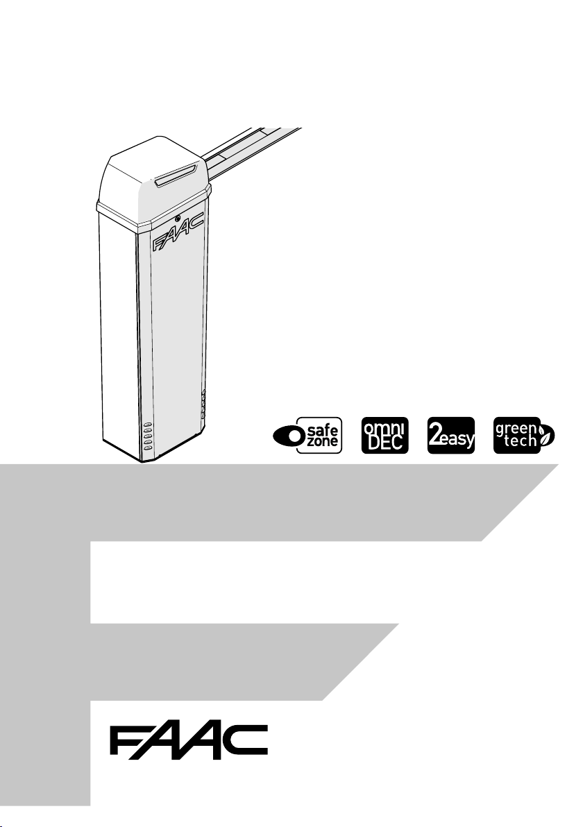
B614
Page 2

FAAC S.p.A. Soc. Unipersonale
Via Calari, 10 - 40069 Zola Predosa BOLOGNA - ITALY
Tel. +39 051 61724 - Fax +39 051 09 57 820
www.faac.it - www.faacgroup.com
© Copyright FAAC S.p.A. dal 2018. Tutti i diritti riservati.
Nessuna parte di questo manuale può essere riprodotta, archiviata, distribuita
a terzi né altrimenti copiata, in qualsiasi formato e con qualsiasi mezzo, sia
esso elettronico, meccanico o tramite fotocopia, senza il preventivo consenso
scritto di FAAC S.p.A.
Tutti i nomi e i marchi citati sono di proprietà dei rispettivi fabbricanti.
I clienti possono effettuare copie per esclusivo utilizzo proprio.
Questo manuale è stato pubblicato nel 2018.
© Copyright FAAC S.p.A. from 2018. All rights reserved.
No part of this manual may be reproduced, archived, distributed to third
parties nor copied in any other way, in any format and with any means,
be it electronic, mechanical or by photocopying, without prior written
authorisation by FAAC S.p.A.
All names and trademarks mentioned are the property of their respective
manufacturers.
Customers may make copies exclusively for their own use.
This manual was published in 2018.
© Copyright FAAC S.p.A. depuis 2018. Tous droits réservés.
Aucune partie de ce manuel ne peut être reproduite, archivée ou distribuée
à des tiers ni copiée, sous tout format et avec tout moyen, qu’il soit électronique, mécanique ou par photocopie, sans le consentement écrit préalable
de FAAC S.p.A.
Tous les noms et les marques cités sont la propriété de leurs fabricants
respectifs.
Les clients peuvent faire des copies pour leur usage exclusif.
Ce manuel a été publié en 2018.
© Copyright FAAC S.p.A. ab dem 2018. Alle Rechte vorbehalten.
Kein Teil dieses Handbuchs darf reproduziert, gespeichert, an Dritte weitergegeben oder sonst auf eine beliebige Art in einem beliebigen Format und
mit beliebigen Mitteln kopiert werden, weder mit elektronischen, noch mechanischen oder durch Fotokopieren, ohne die Genehmigung von FAAC S.p.A.
Alle erwähnten Namen und Marken sind Eigentum der jeweiligen Hersteller.
Die Kunden dürfen nur für den Eigengebrauch Kopien anfertigen.
Dieses Handbuch wurde 2018 veröffentlicht.
© Copyright FAAC S.p.A. del 2018. Todos los derechos están reservados.
No puede reproducirse, archivarse, distribuirse a terceros ni copiarse de
ningún modo, ninguna parte de este manual, con medios mecánicos o
mediante fotocopia, sin el permiso previo por escrito de FAAC S.p.A.
Todos los nombre y las marcas citadas son de propiedad de los respectivos
fabricantes.
Los clientes pueden realizar copias para su uso exclusivo.
Este manual se ha publicado en 2018.
© Copyright FAAC S.p.A. van 2018. Alle rechten voorbehouden.
Niets uit deze handleiding mag gereproduceerd, gearchiveerd, aan derden
openbaar gemaakt of op andere wijze gekopieerd worden, in om het even
welke vorm en met geen enkel middel, noch elektronisch, mechanisch of
via fotokopiëren, zonder schrfitelijke toestemming vooraf van FAAC S.p.A.
Alle vermelde namen en merken zijn eigendom van de respectievelijke
fabrikanten.
De klanten mogen kopieën maken die enkel voor eigen gebruik bestemd zijn.
Dez handleiding werd in 2018 gepubliceerd.
Page 3

EU DECLARATION OF CONFORMITY
The Manufacturer
Company name: FAAC S.p.A. Soc. Unipersonale
Address: Via Calari, 10 - 40069 Zola Predosa BOLOGNA - ITALY
hereby declares under its own exclusive liability that the following product:
Description: Barrier
Model: B614
complies with the following applicable EU legislations:
2014/30/EU
2011/65/EU
Furthermore, the following harmonised standards have been applied:
EN 61000-6-2:2005
EN 61000-6-3:2007 + A1:2011
Bologna, Italy, 01-07-2018
DECLARATION OF INCORPORATION FOR PARTLY COMPLETED MACHINERY
CEO
A. Marcellan
(2006/42/EC ANNEX II P.1, B)
Manufacturer and person authorised to prepare the relevant technical documentation
Company name: FAAC S.p.A. Soc. Unipersonale
Address: Via Calari, 10 - 40069 Zola Predosa BOLOGNA - ITALY
hereby declares that for the partly completed machinery:
Description: Barrier
Model: B614
The essential requirements of the Machinery Directive 2006/42/EC (including all applicable amendments) that have been applied and
fulfilled are as follows:
1.1.2; 1.1.3; 1.1.5; 1.2.1; 1.2.3;1.2.5; 1.2.6; 1.3.1; 1.3.2; 1.3.4; 1.3.6; 1.3.8.1; 1.3.9; 1.4.1; 1.4.2.1; 1.5.1;
1.5.2; 1.5.3 1.5.5; 1.5.6; 1.5.7; 1.5.8; 1.5.10; 1.5.11; 1.5.13; 1.6.1; 1.6.4; 1.7.3; 1.7.4.1; 1.7.4.2; 1.7.4.3
and that the relevant technical documentation has been compiled in compliance with part B of Annex VII.
Furthermore, the following harmonised standards have been applied:
EN60335-2-103-2015
EN12100:2010
EN13849-1:2015 CAT 2 PL “c”
EN13849-2:2012
Other standards applied:
EN 12453:2000
And also undertakes to transmit, in response to a reasoned request by the national authorities, relevant information on the partly
completed machinery by mail or e-mail.
Finally, the manufacturer declares that the above-mentioned partly completed machinery must not be put into service until the final
machine in which it is to be incorporated has been declared compliant with the requirements of the above-mentioned Machinery
Directive 2006/42/EC.
Bologna, Italy, 01-07-2018
CEO
A. Marcellan
ENGLISH
Translation of the original instructions
B614 1 732998 - Rev.A
Page 4

CONTENTS
EU Declaration of conformity ........................... 1
Declaration of incorporation for partly completed machine-
ry ..................................................... 1
1. INTRODUCTION TO THIS INSTRUCTIONS MANUAL .... 4
1.1 Meaning of the symbols used ......................... 4
2. SAFET Y RECOMMENDATIONS ......................... 6
2.1 Installer safety ....................................... 6
2.2 Transport and storage ................................ 7
2.3 Unpacking and handling .............................. 8
2.4 Disposal of the product ............................... 8
ENGLISH
3. B614 .................................................. 9
3.1 Intended use ......................................... 9
3.2 Limitations of use .................................... 9
3.3 Unauthorised use ................................... 10
3.4 Emergency use ...................................... 10
3.5 Product identification ................................ 11
3.6 Technical specifications .............................. 11
3.7 Manual operation ................................... 12
Release procedure .................................... 12
Operation restoration ................................. 12
3.8 Component identification ............................ 13
3.9 Installation components ............................. 14
3.10 Optional accessories ................................ 14
5.9 Earthing the door ................................... 30
5.10 Closing the door ................................... 30
5.11 Closing the upper lid ............................... 31
6. ELECTRONIC INSTALLATION .......................... 32
6.1 Board E614 ......................................... 32
Components ......................................... 32
6.2 Connections ........................................ 34
Control devices ....................................... 34
External loops ........................................ 35
Bus devices ........................................... 35
OUT outputs .......................................... 35
"
24 V
flashing light ................................. 35
Motor ................................................ 35
Encoder .............................................. 35
Beam lights ........................................... 36
Integrated flashing light ............................... 36
XBAT 24 battery ...................................... 36
XF radio module ...................................... 36
Mains supply and earthing............................. 36
7. STARTUP ............................................ 37
7.1 Programming ....................................... 37
Basic programming ................................... 37
Advanced programming .............................. 38
7.2 Operating logics ..................................... 41
EP - Semi-automatic step by step ..................... 41
4. INSTALLATION REQUIREMENTS ...................... 15
Translation of the original instructions
4.1 Mechanical requirements ............................ 15
4.2 Electrical system .................................... 16
4.3 Example system ..................................... 17
5. MECHANICAL INSTALLATION ......................... 18
5.1 Tools required ....................................... 18
5.2 Installing the foundation plate ....................... 19
5.3 Installing the barrier body ........................... 20
Fixing the cables inside the barrier ..................... 21
5.4 Fitting the beam .................................... 22
Preparing the balancer ................................ 22
Rectangular beam .................................... 22
Round beam .......................................... 24
5.5 Fitting the spring .................................... 26
Turnbuckle ........................................... 26
Single spring .......................................... 27
Double spring ......................................... 27
5.6 Accessories on the beam ............................. 28
5.7 Balancing the beam ................................. 28
5.8 Limit switch adjustment ............................. 29
B614 2 732998 - Rev.A
A - Automatic ......................................... 41
AP - Automatic step-by-step .......................... 41
b - Semi-automatic b ................................. 41
bC- Semiautomatic b on opening/ person present C on
closure ............................................... 41
C - Dead-man ........................................ 41
P - Car park ........................................... 41
7.3 SET-UP ............................................. 42
8. PUTTING INTO SERVICE .............................. 43
8.1 Final checks ......................................... 43
8.2 Final operations ..................................... 43
9. ACCESSORIES ......................................... 44
"
9.1 24V
9.2 XBAT 24 emergency battery ......................... 44
9.3 XF radio module ..................................... 45
flashing light ................................ 44
SLH/SLH LR - Memorising the fir st radio control ......... 45
SLH/SLH LR - Memorising other radio controls .......... 45
LC/RC - Memorising the first radio control .............. 45
LC/RC - Remote code memorisation procedure ......... 46
DS - Memorising r adio controls ........................ 46
Page 5

Deleting radio controls from memory .................. 46
9.4 BUS 2easy devices ................................... 47
Connection ........................................... 47
BUS 2easy photocells .................................. 47
Control devices ....................................... 47
BUS 2easy device registration .......................... 48
9.5 Round beam light kit ................................ 49
9.6 Integrated flashing light ............................. 49
9.7 Beam joint kit ....................................... 49
9.8 Hedge .............................................. 50
9.9 Foot ................................................ 50
9.10 Fork ............................................... 50
10. MASTERSLAVE ..................................... 51
Connection ........................................... 51
Slave barrier configuration ............................ 52
11. DIAGNOSTICS ....................................... 53
11.1 LEDs check ......................................... 53
TABLES
11.2 Direction of movement check ....................... 53
11.3 Encoder operation check ............................ 53
11.4 Automation system status check .................... 53
11.5 Check firmware version ............................. 53
11.6 Check of the registered BUS 2easy devices ............ 53
12. MAINTENANCE ...................................... 54
12.1 Routine maintenance ............................... 54
12.2 Spring replacement ................................ 56
12.3 Replacing the Gearmotor ........................... 56
12.4 Fuse replacement .................................. 57
12.5 Operational problems .............................. 57
13. INSTRUCTIONS FOR USE ............................ 58
13.1 Safety recommendations ........................... 58
13.2 Emergency use ..................................... 58
13.3 Manual operation .................................. 59
Release procedure .................................... 59
Operation restoration ................................. 59
ENGLISH
1 Symbols: notes and warnings on the instructions ......4
2 Symbols: safety signs (EN ISO 7010) ...................5
3 Symbols: personal protective equipment ..............5
4 Symbols: markings on packaging .....................7
5 Symbols: markings on product.......................11
6 Technical data ......................................12
7 E614 board technical data ...........................32
8 Basic programming .................................38
10 Advanced programming ............................39
11 Orienting the photocells ............................47
12 Addressing control devices ..........................48
13 Routine maintenance ...............................54
14 Periodic replacements ..............................56
15 Troubleshooting ....................................57
16 Rectangular beam balancing ........................61
17 Round beam S balancing ............................62
9 Default speed ......................................39
ADDENDUM
1 Foundation for barrier in maximum configuration .....60
2 Balancing system ...................................61
B614 3 732998 - Rev.A
Translation of the original instructions
Page 6
1. INTRODUCTION TO THIS INSTRUCTIONS MANUAL
This manual provides the correct procedures and
requirements for installing B614 and maintaining it
in a safe condition.
When drafting the manual, the results of the risk
assessment conducted by FAAC S.p.A. on the entire
product life cycle have been taken into account in
order to implement effective risk reduction measures.
The following stages of the life cycle of the product
have been considered:
- Delivery/handling
- Assembly and installation
- Set-up and commissioning
- Operation
- Maintenance/troubleshooting
ENGLISH
- Disposal at the end of the product’s life cycle
Risks arising from installation and using the product
have been taken into consideration; these include:
- Risks for the installation/maintenance technician
(technical personnel)
- Risks for the user of the automation system
- Risks to product integrity (damage)
In Europe, the automation of a barrier falls under the
Machinery Directive 2006/42/EC and the corresponding harmonised standards. Anyone automating a
barrier (new or existing) is classified as the Manufacturer of the Machine. They are therefore required by
law, among other things, to carry out a risk analysis
of the machine (automatic barrier in its entirety) and
take protective measures to fulfil the essential safety
requirements specified in Annex I of the Machinery
Directive.
Translation of the original instructions
FAAC S.p.A. recommends that you always comply
with the EN 12453 standard and in particular that you
adopt the safety criteria and devices indicated, without
exception, including the dead-man function.
This manual also contains general information and
guidelines, which are purely illustrative and not exhaustive, in order to facilitate the activities carried out by
the Manufacturer of the Machine in all respects with
regard to carrying out the risk analysis and drafting the
instructions for use and maintenance of the machine. It
should be clearly understood that FAAC S.p.A. accepts
no liability for the reliability and/ or completeness of
the above instructions. As such, the manufacturer of
the machine must carry out all the activities required
by the Machinery Directive and the corresponding
harmonised standards on the basis of the actual
condition of the locations and structures where the
product B614 will be installed, prior to commissioning
the machine. These activities include the analysis of all
the risks associated with the machine and subsequent
implementation of all safety measures intended to
fulfil the essential safety requirements.
This manual contains references to European stan-
dards. The automation of a barrier must fully comply
with any laws, standards and regulations applicable in
the country where installation will take place.
Unless otherwise specified, the measurements pro-
Li
vided in the instructions are in mm.
1.1 MEANING OF THE SYMBOLS USED
1 Symbols: notes and warnings on the instructions
WARNING ELECTRIC SHOCK HAZARD - The operation
or stage described must be performed following the
instructions supplied and applicable safety regulations
F
WARNING, PERSONAL INJURY HAZARD OR RISK OF
DAMAGE TO COMPONENTS - The operation or stage
described must be performed following the supplied
!
instructions and applicable safety regulations
WARNING - Details and specifications that must be
complied with in order to ensure that the system
i
operates correctly.
RECYCLING and DISPOSAL - Components and structural
materials, batteries and electronic components must not
be disposed of together with household waste. They must
be taken to authorised disposal and recycling centres
For manual lifting, there should be 1 person for every
20 kg to be lifted
PAGE E.g.: 6 see Page 6
FIGURE E.g.: 1-3 see Figure 1 - item 3
TABLE E.g.: 1 see Table 1
§ CHAPTER/SECTION E.g.: §1.1 see section 1.1
APPENDIX E.g.: 1 see Appendix 1
Automatic operation - automation locked
Manual operation - automation unlocked
B614 4 732998 - Rev.A
Page 7
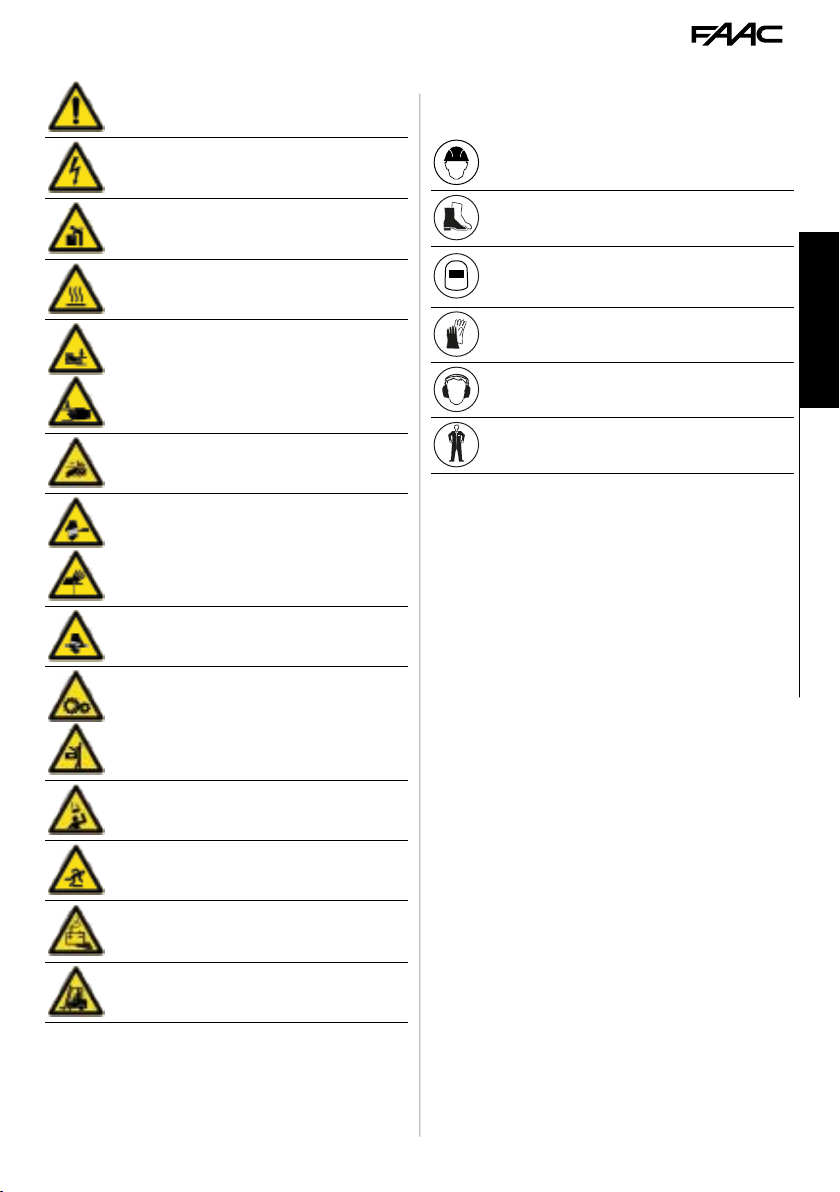
2 Symbols: safety signs (EN ISO 7010)
GENERAL HAZARD - Risk of personal burns or damage
to the parts
3 Symbols: personal protective equipment
Personal protective equipment must be worn to protect against hazards (e.g. crushing, cutting, shearing
etc.):
RISK OF ELECTRIC SHOCK - Risk of electric shock from
live parts
RISK OF CRUSHING, MUSCULAR - SKELETAL PROBLEMS
- Risk of crushing or muscular and skeletal injury when
lifting heavy loads
RISK OF BURNS OR BURNING - Risk of burns or burning
because of very hot parts.
RISK OF CRUSHING - Risk of crushing hands/feet due
to heavy parts
RISK OF CRUSHING HANDS - Risk of crushing hands
due to moving parts
RISK OF CUTS/AMPUTATION/SPEARING - Risk of cuts
due to sharp parts or the use of sharp implements (drill)
RISK OF SHEARING - Risk of shearing due to moving
parts
RISK OF IMPACT/CRUSHING/SHEARING - Risk of impact,
crushing or shearing due to moving parts
Obligation to wear head protection helmet
Obligation to wear safety footwear
Obligation to wear mask/goggles to protect the eyes
from the risk of fragments due to the use of drill or
welding machine
Obligation to wear work gloves
ENGLISH
Obligation to wear ear protectors
Obligatory use of work clothes without parts that could
become caught in moving parts
Translation of the original instructions
RISK OF OBJECTS FALLING FROM ABOVE - Risk of impact
due to objects falling
RISK OF TRIPPING - Risk of tripping due to raised
sections above 5 mm.
RISKS FROM BATTERIES AT THE END OF THEIR LIVES Risk to the environment and health posed by batteries
at the end of their lives due to fluid escaping
RISK OF FORKLIFT TRUCK IMPACT - Risk of being hit by
or colliding with forklift trucks
B614 5 732998 - Rev.A
Page 8

2. SAFETY RECOMMENDATIONS
This product is placed onto the market as “partly
completed machinery”, therefore it cannot be commissioned until the machine in which it will be incorporated has been identified and declared to conform
to the Machinery Directive 2006/42/EC by the actual
Manufacturer.
Incorrect installation and/or incorrect use of the
!
product might cause serious harm to people. Read
and comply with all the instructions before starting
any activity on the product. Keep these instructions
for future reference.
Perform installation and other activities adhering to
ENGLISH
Translation of the original instructions
the sequences provided in the instructions manual.
Always comply with all the requirements contained in
the instructions and warning tables at the beginning
of the paragraphs. Always comply with the safety
recommendations.
Only the installer and/or maintenance technician
is authorised to work on the automation components. Do not modify the original components
in any way.
Close off the work site (even temporarily) and prevent
access/transit. EC countries must comply with the
legislation that transposes the European Construction
Site Directive 92/57/EC.
The installer is responsible for the installation/testing
of the automation and for completing the Register of
the system.
The installer must prove or declare to possess technical
and professional proficiency to perform installation,
testing and maintenance activities according to the
requirements in these instructions.
2.1 INSTALLER SAFETY
Installation activities require special work conditions
to reduce to the minimum the risks of accidents and
serious damage. Furthermore, the suitable precautions must be taken to prevent risks of injury to persons
or damage.
The installer must be in good physical and mental
!
condition, aware of and responsible for the hazards
that may be generated when using the product.
The work area must be kept tidy and must not be
left unattended.
Do not wear clothes or accessories (scarves, bracelets,
etc.) that may get caught in moving parts.
Always wear the personal protective equipment recommended for the type of activity to be carried out.
The required level of workplace lighting must be equal
to at least 200 lux.
Operate CE marked machinery and equipment in compliance with the manufacturer's instructions. Use
work instruments in good conditions.
Use the transport and lifting equipment recommended in the instructions manual.
Use safety-compliant portable ladders of adequate
size, fitted with anti-slip devices at the top and bottom, equipped with retainer hooks.
B614 6 732998 - Rev.A
Page 9
2.2 TRANSPORT AND STORAGE
3
Kg ____
Follow the instructions on the packaging during
!
handling. Two people must move the package. Use
the HANDLES.
4 Symbols: markings on packaging
Read the instructions
This way up indication: do not turn upside down
Store away from water and humidity
Maximum number of stackable pallets
PALLETISED SUPPLY
RISKS
PERSONAL PROTECTIVE EQUIPMENT
Use a forklift or pallet truck, fol-
!
lowing safety regulations to avoid
the risk of impacts or collisions.
ENGLISH
Maximum number of stackable packages
Percent storage humidity
Storage temperature
CE marking
Wear work gloves
Wear safety footwear
20 kg is the MAX weight one person can lift
Weight of package
SINGLE PACKAGE
RISKS
PERSONAL PROTECTIVE EQUIPMENT
For manual lifting, there should
be 1 person for every 20 kg to
be lifted.
STORAGE
Store the product in its original packaging, in closed
and dry premises, protected from the sun and free
from dust and aggressive substances. Protect from
mechanical stress. If stored for more than 3 months,
regularly check the condition of the components and
the packaging.
- Storage temperature: 5°C to 30°C.
- Percentage of humidity: 30% to 70%.
Translation of the original instructions
B614 7 732998 - Rev.A
Page 10
2.3 UNPACKING AND HANDLING
RISKS
PERSONAL PROTECTIVE EQUIPMENT
For manual lifting, there should be 1 person for every
20 kg to be lifted.
Two people must move the package. Use the handles.
ENGLISH
Never manage the barrier by holding the board holder.
!
1. Carefully set the package down on the ground.
2. Cut the packaging to open it right up and remove all
the packaging material.
3. Stand the barrier on the base.
Check that all components are present and intact
Li
1.
4. Dispose of the packaging materials.
The packaging materials (plastic, polystyrene etc.)
!
must not be left within reach of children as they are
potential sources of danger.
When you have finished with them, dispose of the
packaging in the appropriate containers, as per
applicable waste disposal regulations.
2.4 DISPOSAL OF THE PRODUCT
After having dismantled the product, dispose of it
in compliance with the current waste disposal regulations.
Components and structural materials, batteries and
electronic components must not be disposed of
together with household waste. They must be taken
to authorised disposal and recycling centres.
Translation of the original instructions
1 B614 barrier body
2 Top cover
3 Installation accessories
4 Instruction manual
5 Risk signalling
1
B614 8 732998 - Rev.A
2
3
4
5
1
Page 11

3. B614
3.1 INTENDED USE
The B614 barriers are designed for vehicular access
control in residential buildings/apartment complexes.
To move the beam manually, follow the instructions
for manual functioning.
Any other use that is not expressly specified in these
!
instructions is prohibited and could affect the integrity of the product and/or represent a source of danger.
3.2 LIMITATIONS OF USE
Comply with the limitations on frequency of use listed
in the technical data section.
The B614 requires the use of a specific FAAC beam
that conforms to the dimensions indicated in this
manual. Only the FAAC accessories indicated in this
manual should be installed on the beam.
The B614 requires the use of a FAAC spring that is
adequate for counterbalancing the weight of the beam
and the relative accessories.
The barriers with exclusively vehicle access control
must be fitted with suitable visible signs prohibiting
foot traffic. A separate route for foot traffic outside
the range of the beam must be provided and properly
indicated.
If foot traffic cannot be ruled out, the barrier falls within
the scope of the EN 12453 standard.
The presence of weather conditions such as snow, ice
and strong wind, even occasional, could affect the
correct operation of the automation, the integrity of
the components and be a potential source of danger
(see § Emergency use). The limitations of use of the
B614 in wind is equivalent to grade 10 on the Beaufort
Scale (max. speed: 102 km/h).
The installation must be visible during the day and
at night. If it is not, appropriate solutions must be
provided to make the fixed and moving parts visible
(light kit on the beam).
The B614 must be connected to a FAAC electronic
board as indicated in this manual ( Technical characteristics).
Implementing the automation requires the installation of the necessary safety devices, identified by the
installer through an appropriate risk assessment of
the installation site.
ENGLISH
Translation of the original instructions
B614 9 732998 - Rev.A
Page 12

3.3 UNAUTHORISED USE
- Uses other than the intended use are prohibited.
- It is prohibited to install the automation system
outside of the limits specified in the Technical Data
and Installation Requirements sections.
- It is forbidden to use B614 in a constructional
configuration other than the one provided by the
manufacturer.
- No component part of the product may be mo-
dified.
- It is prohibited to install the automation system
on escape routes.
- It is prohibited to install the automation system in
environments in which there is a risk of explosion
and/or fire: the presence of flammable gases or
ENGLISH
fumes is a serious safety hazard.
- It is prohibited to power the system with energy
sources other than those specified.
- It is prohibited to integrate commercial systems
and/or equipment other than those specified, or
use them for purposes not intended and authorised
by their respective manufacturers.
- Do not allow water jets of any type or size to come
into direct contact with the actuator.
- Do not expose the actuator to corrosive chemicals
or atmospheric agents.
- Do not expose the barrier to direct jets of water of
any type and size.
- Do not expose the barrier to aggressive chemical
or environmental agents.
- The barrier may not be used to move moving parts
other than the beams produced by FAAC specified
Translation of the original instructions
in this manual.
- Use to control pedestrian access, bicycle traffic and
the passage of animals is prohibited.
- Use of the barrier at level crossings is prohibited.
- Use of the barrier on public thoroughfares is
prohibited.
- It is prohibited to use and/or install accessories
which have not been specifically approved by
FAAC S.p.A.
- It is prohibited to use the automation system before
performing commissioning.
- It is prohibited to use the automation system in the
presence of faults which could compromise safety.
- It is prohibited to use the automation system with
the fixed and/or mobile guards removed or altered.
- Do not use the automation system unless the area
of operation is free of persons, animals or objects.
- Do not enter/remain in the area of operation of the
automation system while it is moving.
- Do not try to prevent the movement of the auto-
mation system.
- Do not climb onto the actuator.
- Do not climb or catch on to the beam or lift yourself
B614 10 732998 - Rev.A
up on it. Do not climb on the barrier cabinet.
- Do not allow children to approach or play in the
area of operation of the automation system.
- Do not allow the control devices to be used by
anyone who is not specifically authorised and
trained to do so.
- Do not allow the control devices to be used by
children or persons with mental and physical deficiencies unless they are supervised by an adult
who is responsible for their safety.
During manual handling, accompany the beam slowly
!
for the entire stroke. Do not let the beam travel freely.
3.4 EMERGENCY USE
In emergencies or if there is a fault, turn off the power
supply to the automation and disconnect the buffer
batteries if there are any. If the beam can be moved
safely by hand, use the MANUAL OPERATION mode;
otherwise place the automation out of service until it
has been reset/repaired.
In the case of a breakdown, the automation must be
reset/repaired exclusively by the installer/maintenance
technician.
Page 13
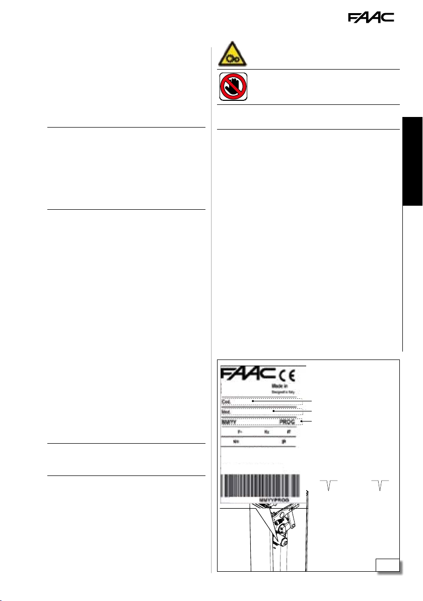
3.5 PRODUCT IDENTIFICATION
The product is identified by the plate (2).
3.6 TECHNICAL SPECIFICATIONS
The B614 is an electromechanical barrier with a E614
electronic board fitted. The B614 must be installed
on the specific foundation plate and set onto a plinth.
RH/LH barrier B614 makes it possible to build a right
hand or left hand barrier without modifying the
barrier body.
The barrier will be installed with the door towards
Li
the inside of the property.
The barrier is defined by observing it from the door
side:
- RH barrier (right): the beam closes towards the
right (in a clockwise direction)
- LH barrier (left): the beam closes towards the left
(in an anticlockwise direction)
Irreversible system To allow manual operation, the
release manoeuvre must be performed.
Encoder B614 is fitted with an encoder. The encoder
constantly detects the precise position of the beam
and makes it possible to manage the end of stroke
and slowing downs stored with the set up.
Anticrushing operation The encoder allows the board
to create the anticrushing feature:
- the recognition of an obstacle during closure cau-
ses the manoeuvre to be reversed
- the recognition of an obstacle during opening
causes the beam to stop.
Adjustable end of stroke The barrier is fitted with an
adjustable mechanical end of opening and closing
stroke feature.
Equipment A rectangular or round beam can be
installed. The components necessary for the installation and the optional equipment are listed in the
dedicated sections.
Balancing system The balancing spring must be used
FAAC. The single or double spring depending on the
length and configuration of the installed beam must
be fitted in the definite fitting positions.
The balancing system is important for safety reasons
!
to ensure the stability and control of the beam during
movement and keep it operating properly over time.
Master-Slave Configuration To install two barriers that
open in opposite directions it is necessary to create
the Master-Slave configuration.
5 Symbols: markings on product
Risk of crushing between the moving parts. Present
on the balancer
Risk of cutting, crushing or shearing of fingers or a
hand between the beam and the barrier body. It must
be placed on the trunk by the installation engineer.
"DANGER OF AUTOMATIC MOVEMENT" (not supplied) It must be
placed on the trunk by the installation engineer.
FAAC S.p.A. Soc. Unipersonale
Via Calari, 10 - 40069 Zola Predosa BOLOGNA
Italy
••••••
BARRIER B614 230V
••••••
••••••
•••• ••••
••••
••••••
Sale code
Product name
••••••
••
IDENTIFICATION NUMBER
Month/year of production +
progressive number for the
month of production
Example:
0116 0001
••••••
made in:
January 2018
progressive:
0001
ENGLISH
Translation of the original instructions
B614 11 732998 - Rev.A
2
Page 14
6 Technical data
B614 220-240 V ~ B614 115 V ~
Power supply voltage 220-240 V~ 50/60 Hz 115V~ +/-10% 50/60 Hz
Electric motor 24 V
Max power 165 W 165 W
Max torque 300 Nm 300 Nm
Opening time (80°)
- beam 3 m
- beam 5 m
Use frequency Continuous use Continuous use
Ambient operating temperature -20 °C to +55 °C -20 °C to +55 °C
Protection rating IP 55 (control board) - IP 44 IP 55 (control board) - IP 44
Dimensions (L x D x H) 247 x 357 x 1163 mm 247 x 357 x 1163 mm
ENGLISH
Weight 40 kg 40 kg
FAAC foundation plate
Dimensions (L x H) 230 x 305 mm
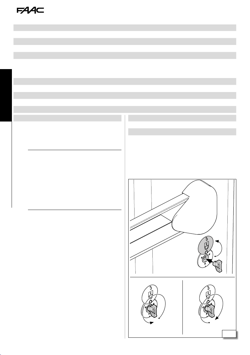
3.7 MANUAL OPERATION
- Performing the release manoeuvre when there is
!
no electrical power.
- Performing the release manoeuvre only when the
beam is at a standstill.
- During manual handling, accompany the beam
slowly for the entire stroke. Do not let the beam
travel freely.
- Do not leave the barrier unblocked: after carrying
Translation of the original instructions
out the manual movement, restore automatic
operation.
"
< 2 sec.
< 3 sec.
"
24 V
< 2 sec.
< 3 sec.
FAAC beam Beam length
Rectangular beam 1.35 ... 4.85 m max
Round beam 1.40 ... 5.20 m max
RELEASE PROCEDURE
1. 3 Open the lock cover. Insert the key and turn it
once anticlockwise until it stops (1).
2. Move the barrier manually.
3. Restore the operation.
OPERATION RESTORATION
1. 3 Insert the key and turn it twice clockwise
until it stops (2).
2. Check that manual movement is inhibited.
3. Remove the key and close the cover.
1
B614 12 732998 - Rev.A
2
3
Page 15
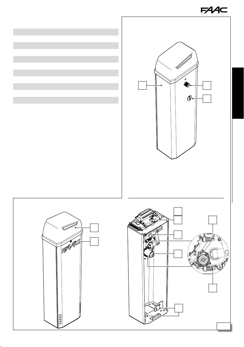
3.8 COMPONENT IDENTIFICATION
Standard equipment on the barrier body (4):
1 Bearing trunk
2 Drive shaft
3 Beam release device (triangular key)
4 Top cover
5 Door with lock
6 E614 control board
7 E614 control board cover
8 Balancer/ upper spring fixing
9 Electromechanical gearmotor with Encoder
10 Slot for lower spring fixing
11 Limit switches
B614 beam side
1
2
3
ENGLISH
B614 door side
6
7
4
8
5
9
10
B614 13 732998 - Rev.A
Translation of the original instructions
11
11
4
Page 16
3.9 INSTALLATION COMPONENTS
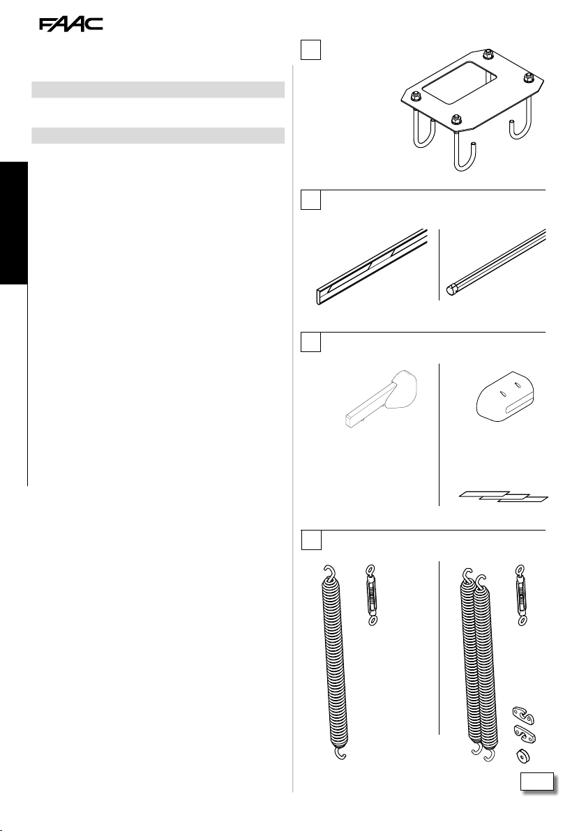
The installation requires the following FAAC components supplied separately (5):
1 Foundation plate
2 Rectangular or round beam (the reflecting paper for round
beam are supplied separately)
3 Fixing pocket for the installed beam (rectangular or round)
4 Single or double balancing spring
3.10 OPTIONAL ACCESSORIES
For the FAAC accessories for the B614 see the chapter
§ 9.
ENGLISH
1
Foundation plate
2
Rectangular beam
3
Pocket for rectangular
beam
Round beam
Pocket for round beam
Adhesive reflectors for
Translation of the original instructions
4
Single spring Double spring
B614 14 732998 - Rev.A
round beam
5
Page 17
4. INSTALLATION REQUIREMENTS
4.1 MECHANICAL REQUIREMENTS
The mechanical structural components must comply
with the requirements of EN 12604:2002. Before
installing the automation, the suitability of the mechanical requirements must be established and any work
that is necessary in order to meet them carried out.
The essential mechanical requirements are as follows:
Firm ground to support the weight of the barrier with
!
flat, horizontal paving. There must be no chance of
water accumulating in the installation area.
The thresholds and protrusions of the paving must
be appropriately shaped in order to prevent the risk
of sliding or slipping.
For the creation of detection loops, refer to the specific
instructions.
Presence of a safety area between the wall (or other
fixed element) and the end of the beam, to protect
against the risk of persons becoming trapped/
crushed.
Presence of safety areas between the fixed and
moving parts to prevent hands from being crushed.
For the minimum dimensions to prevent crushing/
shearing of body parts, refer to EN 349. For the
safety distances required to prevent danger zones
being reached, refer to ISO 13857.
Presence of enough working space needed for the installation manoeuvres and subsequent maintenance
operations, bearing in mind the opening of the service
door and the positioning/removal of the cabinet and
any other elements.
Absence of fixed or mobile obstacles to the movement of the beam (e.g.: branches, overhead cables,
ceilings).
If the installation area presents the possibility of vehicle impact, provide adequate protective structures to
protect the barrier body.
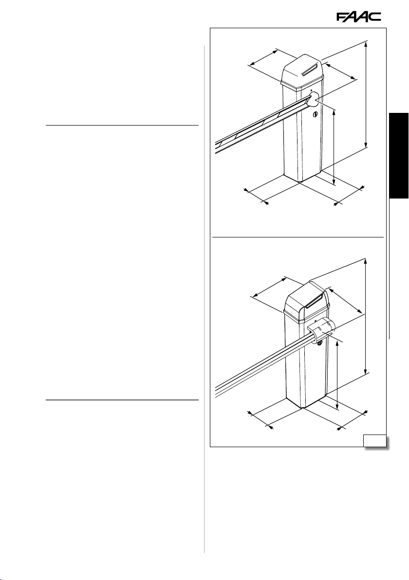
230
360
300
1163
860
ENGLISH
305
360
385
1163
Translation of the original instructions
860
230
B614 15 732998 - Rev.A
305
6
Page 18

4.2 ELECTRICAL SYSTEM
Always shut off the power supply before performing
F
any work. If the disconnect switch is not in view,
apply a warning sign stating “WARNING - Maintenance in Progress”.
The electrical system must comply with applicable
!
legislation in the country of installation.
Use components and materials with CE marking
which are compliant with the Low Voltage Directive
2014/35/EU and EMC Directive 2014/30/EU.
The power supply line for the automation must be
fitted with a multi-pole circuit breaker, with a suitable
tripping threshold, a contact opening distance of at
ENGLISH
Translation of the original instructions
least 3 mm and a breaking capacity that complies
with current regulations.
The power supply for the automation must be fitted
with a 30 mA differential switch.
The metal parts of the structure must be earthed.
Check that the protective earthing system complies with applicable regulations in the country of
installation.
The electrical cables of the automation system must
be of a size and insulation class that is compliant
with current legislation and laid in appropriate rigid
or flexible conduits, either above or below ground.
Use separate conduits for the power supply and the
12-24 V control devices / accessories cables.
In the case of a Master-Slave configuration, a cable
conduit has to be installed for the cables that connect
the two electronic boards.
Check buried cable plans to ensure that there are no
other electrical cables in proximity to the planned
digging/drilling locations to prevent the risk of
electrocution.
Check that there are no pipes in the vicinity as well.
The external electronic board must be housed in an
enclosure that has a minimum IP 44 protection rating
and fitted with a lock or another type of device to prevent access by unauthorised persons. The enclosure
must be located in an accessible and non-hazardous
area and at least 30 cm from the ground. The cable
outlets must face downwards.
The conduit fittings and the cable glands must prevent
the entry of moisture, insects and small animals.
Protect extension connections using junction boxes
with an IP 67 protection rating or higher.
The overall length of the BUS cables must not exceed
100 m.
The barrier must always be visible to prevent it from
being hit accidentally; an adequate lighting system
is required.
It is recommended to install a flashing light in a visible
position to indicate when it is moving.
For the creation of detection loops, refer to the relative
instructions.
The control accessories must be positioned in areas
that are always accessible and not dangerous for
the user. It is recommended to position the control
accessories within the field of view of the automation.
If an emergency stop button has been installed, it
must be EN13850 compliant.
Comply with the following heights from the ground:
- control accessories = minimum 150 cm
- emergency buttons = maximum 120 cm
If the manual controls are intended to be used by
disabled or infirm persons, highlight them with
suitable pictograms and make sure that these users
are able to access them.
B614 16 732998 - Rev.A
Page 19
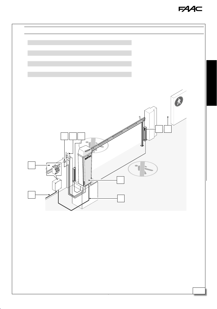
4.3 EXAMPLE SYSTEM
The example is purely an illustration and is only one of the possible applications of the B614.
!
Example system Minimum wire cross section
1 Barrier B614
2 Mains power supply 3G 1.5 sq. mm
3 Circuit breaker
4 Key button
5 Flashing light
6 BUS 2easy photocells 2 x 0.5 sq. mm
7 Foot traffic route
4
5 6
3
ENGLISH
6 7
1
2
B614 17 732998 - Rev.A
2
Translation of the original instructions
7
Page 20

5. MECHANICAL INSTALLATION
Carry out the work with the power supply discon-
F
nected.
5.1 TOOLS REQUIRED
The installation must comply with Standards
!
EN 12453 and EN 12445.
Mark off the work site and prohibit access/transit. Before the barrier is fixed to the foundation there
are risks of tripping and falls.
When working in the box there are risks of cutting,
shearing, crushing hands due to the presence of
moving parts. Until the installation is completed,
the partially installed barrier must always be left
blocked and with the door and upper lid always
ENGLISH
Translation of the original instructions
closed to prevent access to the electronic parts and
the moving mechanical pars.
Never install the beam before fixing the barrier body
and checking it.
Until the installation is complete, never leave the barrier unguarded with the beam fitted. If the beam is
fitted, the barrier must be locked with the beam open.
If installation is outside, it must be done in good
weather without rain or gusts of wind. If it is
raining, an adequate shelter for the barrier must be
made until the mechanical and electronic installation
is complete.
Never manage the barrier by holding the board holder.
Spanner
8-13-17-19
Allen key
4-6
Level
TOOL with TORQUE ADJUSTMENT
Where necessary for safety, a torque wrench with the
specified tightening torque will be shown.
FASTENING TORQUE VALUE
The torque wrench and the tightening torque in Nm
is shown in the figures. E.g.: HEX WRENCH 6 set at
2.5 Nm
2.5
Nm
6
B614 18 732998 - Rev.A
Page 21
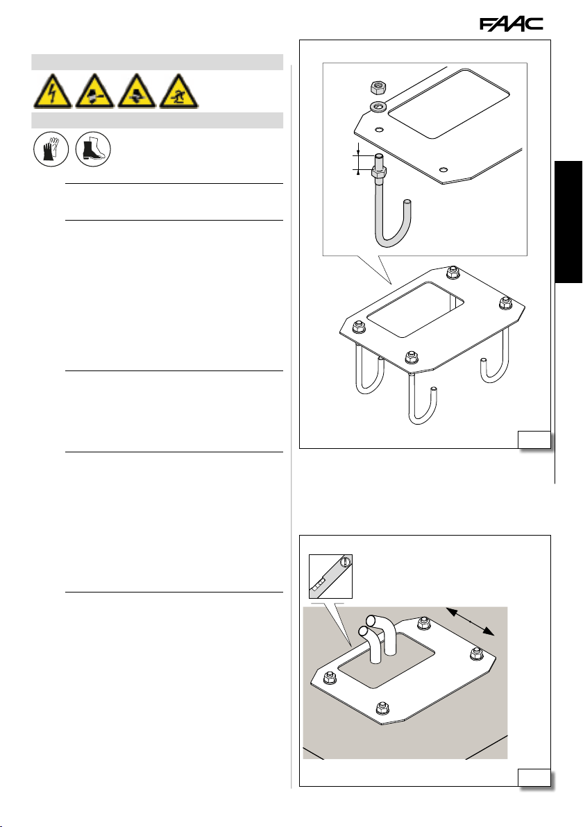
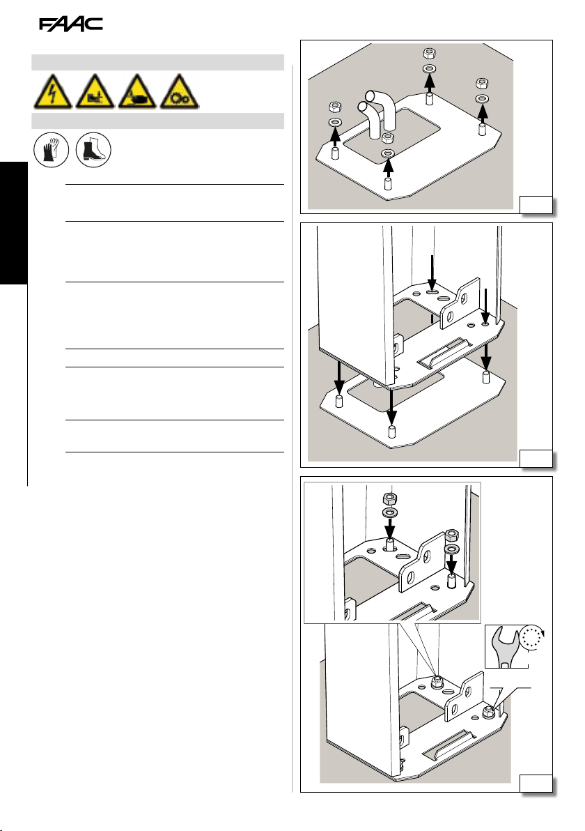
5.2 INSTALLING THE FOUNDATION PLATE
RISKS
PERSONAL PROTECTIVE EQUIPMENT
Carry out the work with the power supply discon-
F
nected.
The barrier must be installed with the base plate
!
- The foundation schematic appended to this manual
gives the characteristics of the foundation as pure
approximations. The schematic considers the barrier
applied to the maximum limits indicated in this
manual and under the most arduous conditions. The
installation engineer is responsible for the evaluation
of the foundation materials and dimensions on the
basis of the characteristics of the ground and place
of installation. Perform structural calculations
where necessary.
1. Make the hole in the ground. Fill it with concrete,
allowing the cable conduits to protrude.
2. (8) Assemble the base plate.
3. (9) Immerse the base plate in the foundation
leaving the surface exposed.
The plate must be in the centre of the plinth.
!
The hole for the cables to pass through must correspond with the orientation planned for the barrier
(barrier side, door side).
The cable conduits must protrude from the hole in the
plate by approximately 20 cm.
Check the plate is horizontal using a spirit level.
Clean the concrete off the surface of the plate and
the nuts with washers so they can be removed when
necessary.
4. Wait for the concrete to set.
22 mm
ENGLISH
8
Translation of the original instructions
beam side
B614 19 732998 - Rev.A
B614 door
side
9
Page 22
5.3 INSTALLING THE BARRIER BODY
RISKS
PERSONAL PROTECTIVE EQUIPMENT
Carry out the work with the power supply discon-
F
nected.
Before you start, make sure that the plinth's concrete
!
ENGLISH
Translation of the original instructions
has solidified.
In this phase the barrier must be locked.
Never manage the barrier by holding the board holder.
1. (10) Remove the 4 nuts with washers from the
plate
2. (11) Place the barrier body on the foundation, at
the four fixing points.
Be careful not to damage the electrical cable tubes.
!
3. (12) Fix the body of the barrier in post ion using
a nut with washer on every fixing point of the
foundation.
Use the torque wrench to tighten to the torque shown
!
in the figure.
10
11
B614 20 732998 - Rev.A
50 Nm
19
12
Page 23
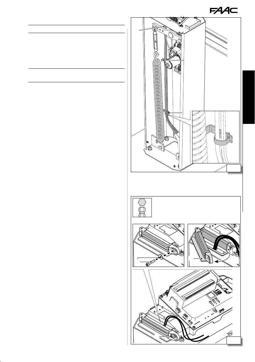
FIXING THE CABLES INSIDE THE BARRIER
130 cm of cable are necessary.
Li
1. (13) Arrange the cables inside the barrier. Fix
the cables with the cable ties provided 1, 2 and 3.
2. (14) Remove bolt with washer 1. Open cable
tie 2. Bring the cables to the board.
3. Use the screw and washer 1 to close the cable tie.
The electrical connections must be made after com-
Li
pleting the mechanical installation
3
2
1
13
4
1
2
ENGLISH
Translation of the original instructions
1
B614 21 732998 - Rev.A
14
Page 24
5.4 FITTING THE BEAM
RISKS
PERSONAL PROTECTIVE EQUIPMENT
- Carry out the work with the power supply di-
!
sconnected.
- Before installing the beam, check the fixing of the
barrier body with the tightening torques indicated.
ENGLISH
- Two people must move the beam.
- If necessar y, cut the beam, do not cut the end with
the fixing hole in it. After the cutting remove any
sharp borders and burs.
Before fitting the beam, check the integrity of the
lower rubber protection edging.
1
2
15
spacer not used
1
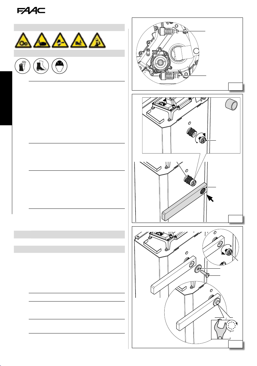
PREPARING THE BALANCER
Before installing the beam, it is necessary to turn the
balancer in the closed beam position.
This phase requires the release of the barrier.
!
- Keep away from the moving elements inside the
box.
- To move the balancer, turn the drive shaft, making
use if necessary of the beam fixing lever. Do not use
Translation of the original instructions
other tools
1. Perform the release manoeuvre.
2. Turn the shaft so as to bring the balancer into
contact with the closing limit switch (15).
Closing limit switch
LH barrier 1
RH barrier 2
3. Restore the automatic operation.
RECTANGULAR BEAM
1. (16) Screw up the guide 1 in the drive shaft.
2. Insert lever 2 in the drive shaft horizontally in
contact with seeger ring 3.
The spacer must not be used and must be eliminated.
Li
3. (17) Removing guide 1 and replacing it.
4. Fix in position with screw 2, interposing washer 3.
Use the torque wrench to tighten to the torque shown
!
in the figure.
3
2
16
1
3
2
60 Nm
19
17
B614 22 732998 - Rev.A
Page 25
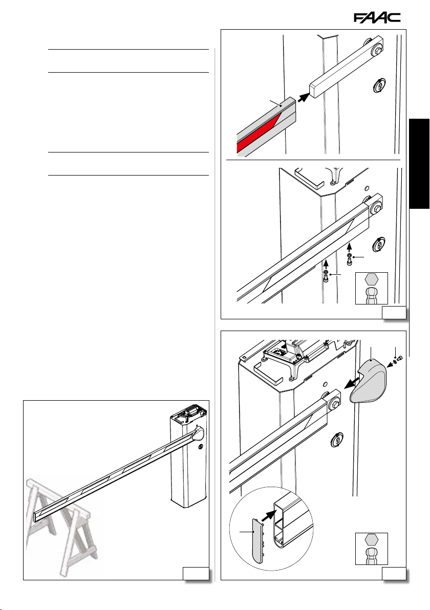
5. (18) Insert beam 1 in the lever.
To make the insertion of the beam easier, use a stand
!
for resting it at the end.
6. Line up the two holes underneath (slide the lower
edging temporarily to uncover the holes).
7. Fix the beam with screws 2, interposing the washers
(reposition the lower edging).
8. (19) Inser t cover 1 and fix it with screw 2, interpo-
sing the washer.
9. Insert the cover 3 at the end of the beam.
Leave the beam supported to take the weight until
!
the installation of the spring is complete (20).
1
ENGLISH
2
2
6
18
3
B614 23 732998 - Rev.A
21
Translation of the original instructions
5
19 20
Page 26

ROUND BEAM
1. (21) Screw up the guide 1 in the drive shaft.
2. Insert plate 2 in the drive shaft horizontally in
contact with seeger ring 3.
Position the plate with the holes 4 at the bottom.
!
The spacer 5 must not be used and must be elimi-
Li
nated.
3. (22) Removing guide 1 and replacing it.
4. Insert the adaptor 2, horizontally.
5. Fix in position with screw 3, interposing washers
4 and 5.
Use the torque wrench to tighten to the torque shown
!
ENGLISH
Translation of the original instructions
in the figure.
6. (23) Insert the beam 1 in a horizontal position.
To make the insertion of the beam easier, use a stand
!
for resting it at the end.
7. Insert counter plate 2.
8. Fix in position with screws 3, interposing the
washers.
Use the torque wrench to tighten to the torque shown
!
in the figure.
3
4
5
1
2
4
21
1
2
4
5
3
60 Nm
19
25 Nm
13
B614 24 732998 - Rev.A
22
1
2
3
23
Page 27

9. (24) Insert cover 1 and fix it with the screws 2.
10. (25) Apply the reflective papers 1 on both sides
of the beam.
11. I nsert cover 2 at the end of beam and fix with screws 3.
Leave the beam supported to take the weight until
!
the assembly of the spring is complete.
1
2
ENGLISH
24
3
2
B614 25 732998 - Rev.A
3
1
Translation of the original instructions
25
Page 28

5.5 FITTING THE SPRING
RISKS
PERSONAL PROTECTIVE EQUIPMENT
The balancing of the barrier requires:
- fitting of the turnbuckle in the appropriate position
- fitting of the appropriate spring: single or double
- manual adjustment of the turnbuckle
ENGLISH
Translation of the original instructions
- Carry out the work with the power supply di-
!
sconnected.
- The spring appropriate for the configuration and
Li
length of the beam is defined in the balancing charts
(see 2). Respect the holes for hooking to the
balancer and the base indicated.
- The accessories on the beam must be considered
when choosing the balancing spring (single or double). Following the addition or elimination of the
accessories at a later time, it might be necessary to
change the spring.
TURNBUCKLE
This phase requires the release of the barrier.
!
- Keep away from the moving elements inside the
box.
- Do not leave the beam vertical when the barrier
is unlocked.
1. Perform the release manoeuvre.
2. (26) Lift the beam completely vertically.
3. Restore the automatic operation.
4. (27) Align the bushing 1 and the turnbuckle
2 with the appropriate hole (see 2). Fix in
position with screw 3, interposing washer3.
Use the torque wrench to tighten to the torque shown
!
in the figure.
!
26
1 2 3
17
B614 26 732998 - Rev.A
15 Nm
27
Page 29

SINGLE SPRING
1. Lengthen the turnbuckle by manually unscrewing it
to facilitate the operation.
2. (28) Hook the spring onto the turnbuckle and
the appropriate slot at the bottom of the barrier
body (see 2).
3. Shor ten the turnbuckle by screwing it up manually to
place the spring under tension.
Keep away from the spring coils.
!
4. Restore the automatic operation.
DOUBLE SPRING
1. Lengthen the turnbuckle by manually unscrewing
it to facilitate the operation.
2. Lower bracket (29): Connect the plate 1 to
the slot on the base of the barrier body as shown
in 2 and lock it in position using the element
x. Connect the 2 springs.
3. Upper bracket (29): Connect the plate 2 to the
springs and then to the turnbuckle.
4. Shor ten the turnbuckle by screwing it up manually
to place the spring under tension.
Keep away from the spring coils.
!
5. Restore the automatic operation.
1
ENGLISH
x
28 29
B614 27 732998 - Rev.A
Translation of the original instructions
Page 30

5.6 ACCESSORIES ON THE BEAM
The accessories on the beam must be considered
!
when choosing the balancer spring (single or double).
The accessories on the beam must be fitted before
balancing the beam. If the accessories are added
or removed later it may be necessary to change
the spring. After a modification of the beam, it is
necessary to balance it again.
The spring appropriate for the configuration and
length of the beam is defined in the balancing charts
(see 2).
See § 9 for fitting accessories to the beam.
Li
5.7 BALANCING THE BEAM
ENGLISH
RISKS
PERSONAL PROTECTIVE EQUIPMENT
This phase requires the release of the barrier.
!
- Performing the release manoeuvre when there is
no electrical power.
- Keep away from the moving elements inside the
box and from the coil spires.
Translation of the original instructions
- Do not leave the beam vertical when the barrier
is unlocked.
45°
!
See the specific instructions for balancing a jointed
Li
beam.
1. Perform the release manoeuvre.
2. Bring the beam to 45° and release it: the beam is
balanced correctly when it stays in position.
3. Make the adjustment, if necessary:
- if the beam wants to open, the turnbuckle must
be extended
- if the beam wants to close, the turnbuckle must
be shortened
4. Repeat the adjustment until it is correctly balanced.
5. Restore the automatic operation.
B614 28 732998 - Rev.A
30
Page 31

5.8 LIMIT SWITCH ADJUSTMENT
RISKS
PERSONAL PROTECTIVE EQUIPMENT
1
A
2
3
The gearmotor is supplied with the limit switches
already adjusted.
It is possible to work on the limit switches to adjust
the beam’s horizontal status and verticality (31).
Limit switch A Limit switch B
RH barrier vertical beam horizontal beam
LH barrier horizontal beam vertical beam
This phase requires the release of the barrier.
!
- Performing the release manoeuvre when there is
no electrical power.
- Keep away from the moving elements inside the
box and from the coil spires.
- Do not leave the beam vertical when the barrier
is unlocked.
1. At the same time, loosen lock nut 1 and the screw 2.
2. Keep the lock nut 1 still and manually regulate the
stop with screw 3.
3. Block the lock nut 1 with the hex wrench and
tighten the screw with Allen key 2.
4. Check the correct adjustment of the limit
switch. Repeat the sequence if necessary. At
the end, tighten screw 2 definitively with the
indicated torque.
Use the torque wrench to tighten to the torque shown
!
in the figure.
B
2
1
2
15 Nm
13
6
1
3
ENGLISH
31
Translation of the original instructions
B614 29 732998 - Rev.A
Page 32

5.9 EARTHING THE DOOR
1. (32) Use the cable supplied and fix it using
the toothed washer and nut on the base and on
the door. Respect the insertion order indicated
in the figure.
5.10 CLOSING THE DOOR
The door must be closed before any manoeuvres are
!
performed, even manually.
Handle the door carefully so as not to damage the
earth cable.
1. (33) Insert the lower slot of the door in its place
1, at the bottom of the box.
2. Close the door and fix it in place with screws 2
ENGLISH
(provided).
8
32
2
Translation of the original instructions
B614 30 732998 - Rev.A
8
2
1
33
Page 33

5.11 CLOSING THE UPPER LID
If there is a flashing light kit, insert the connector
Li
before closing the cover (see § 9).
1. (34) With the cover inclined, insert markers
1 in slots 2 on the box (rod side), then lower it on
the opposite side.
2. Close with the key: turn in an anticlockwise
direction.
3. Check the closure of the cover: try to lift it from
the two beam ends at the same time and then on
the opposite side.
For the closure seal to be effective, it is necessary
Li
for the door of the barrier to be closed and fixed
definitively.
ENGLISH
1
2
B614 31 732998 - Rev.A
Translation of the original instructions
34
Page 34

6. ELECTRONIC INSTALLATION
RISKS
PERSONAL PROTECTIVE EQUIPMENT
6.1 BOARD E614
ENGLISH
7 E614 board technical data
230V~ 115V~
Power supply voltage 220-240 V~ 50/60 Hz 115V~ +/-10% 50/60 Hz
Max power 150 W 150 W
Accessories output voltage 24 V
Max. accessories load 500 mA 500 mA
Max. BUS 2easy accessories load 500 mA 500 mA
Max. flashing light load 24 V
Ambient operating temperature -20 °C to +55 °C -20 °C to +55 °C
COMPONENTS
See figure 35
Translation of the original instructions
BOARD:
J1 Mains power supply terminal board
J3 BUS 2easy terminal board
J6 Accessory/input terminal board
J7 Connector for XF radio module
J8 Connector for XBAT 24 battery
J10 Terminal board for external detector LOOP1
J11 Connector for encoder
J13 Terminal board for external detector LOOP2
J16 Terminal board for external flashing light
J18 Terminal board for the beam lights
J20 Terminal board for outputs
J21 Connector for integrated flasher
J23 Connector for motor
F3 Board protection fuse (F3 = T2.5A)
DISPLAY Programming display
"
"
15 W 24 V " 15 W
ALWAYS DISCONNECT THE POWER SUPPLY before
F
working on the board. Turn power on only after
having made all the electrical connections and carried
out the preliminary start-up checks.
The board cover must never be removed unless the
board is to be replaced. No installation operation
requires the removal of the cover.
"
24 V
BOARD:
DL1 Device signalling LED to BUS 2easy ACTIVE
DL2 BUS 2easy “BUS MON“ diagnostic signalling LED
DL3 “RADIO1” (OMNIDEC) signalling LED
DL4 “RADIO2” (OMNIDEC) signalling LED
DL5 Error/alarm signalling LED
DL8 EMER status LED
DL9 STOP/FSW-CL status LED
DL10 CLOSE status LED
DL11 OPEN status LED
DL12 LOOP1 status LED
DL13 LOOP2 status LED
B614 32 732998 - Rev.A
Page 35

F3 J8
6 A
N
L
M
PE
N
L
MOT
MOT
AC MAIN
MOT
J1
J23
J7
J11
DL13
LOOP 2
LOOP 2
DISPLAY
DL1
DL2
BUS
BUS
+ F-
+ -
J20
8.8
F
GND
+24V
RADIO 1
RADIO 2
ERROR
ALARM
OUT 2
OUT 1
OUT 4
OUT 3
DL3
DL4
DL5
LAMP
LAMP
XF 433-868
J16
"
24 V
15 W max
ENGLISH
Translation of the original instructions
BLG
COM
BLR
ENC
LIGHT
BEAM
TRAFFIC
LAMP
J6
J18
J21
DL11
1
OPEN
2
CLOSE
DL10
345
EMER
STOP
DL9
GND
DL8
6
+24V
DL12
J10J3J13
LOOP 1
LOOP 1
2.5 3
8
B614 33 732998 - Rev.A
35
Page 36
BUS
BUS
GND
LAMP
OUT 4
OUT 3
OUT 2
OUT 1
+24V
LOOP 2
LOOP 2
LOOP 1
LOOP 1
AC MAIN
ENC
TRAFFIC
LAMP
LIGHT
BEAM
6.2 CONNECTIONS
Before making electrical connections, cut off the
F
automation power supply. If the disconnect switch
is not in view, apply a warning sign stating “WARNING
- Maintenance in Progress”.
In Master-Slave configuration see § 10.
Li
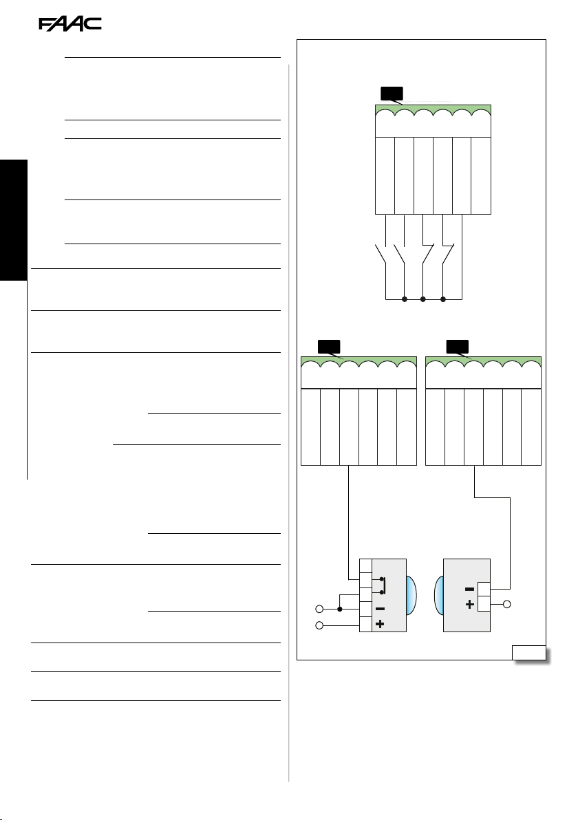
CONTROL DEVICES
(36) Connect the devices to the terminal board
J6 of the board.
Multiple NO contacts on same input must be con-
Li
nected in parallel. Multiple NC contacts on same input
ENGLISH
Translation of the original instructions
must be connected in series.
TERMINAL BOARD J6:
1 OPEN
2 CLOSE
STOP
3
FSW-CL
4 EMER
7 GND
8-9 +
STOP input configured as FSW-CL
For the connection of photocells with relay contact, it
is necessary to configure the STOP input as FSW-CL.
Connect the negative of the transmitter (TX) power
supply of the photocells to an OUT output configured
NO contact, connect a button or other pulse
giver that commands the opening of the
barrier, by closing a contact
NO contact, connect a button or other pulse
giver that commands the closure of the
barrier, by closing a contact
Configured as STOP (default):
NC contact, connect a button or other pulse
giver that commands the stopping of the
barrier, by opening a contact
If NO device is connected, make
Li
a jump with GND
Configured as FSW-CL (see SP function in
Advanced programming):
NC contact, connect a photoelectric cell or
other device that commands the inversion
on opening, by opening a contact during
the closure
If NO device is connected, make
Li
a jump with GND
NC contact, connect a button or other pulse
giver that commands the emergency opening
of the barrier, by opening a contact
If NO device is connected, make
Li
a jump with GND
Accessories power supply negative and
common contact (1 A max.)
Accessories power supply positive 24 V
(1 A max.).
"
J6
1
2
OPEN
CLOSE
J6 J20
1
2
3
4
5
6
STOP
CLOSE
OPEN
5
6
1
2
3
4
5
GND
EMER
+24V
3
STOP
GND
4
5
GND
EMER
+24V
TXRX
6
+24V
OUT 2
OUT 1
1
2
OUT 4
OUT 3
6
36
B614 34 732998 - Rev.A
Page 37
BUS
BUS
GND
LAMP
OUT 4
OUT 3
OUT 2
OUT 1
+24V
LAMP
XF 433-868
LAMP
LAMP
XF 433-868
PE
N
L
6 A
AC MAIN
PE
N
L
6 A
AC MAIN
ENC
LIGHT
MOT
MOT
M
as Fail-Safe. In this way the functioning of the photocells is checked before each closure: the test consists
in breaking the power supply to the TX momentarily
and checking the change of status of the input. If the
test fails the electronic board does not command the
movement.
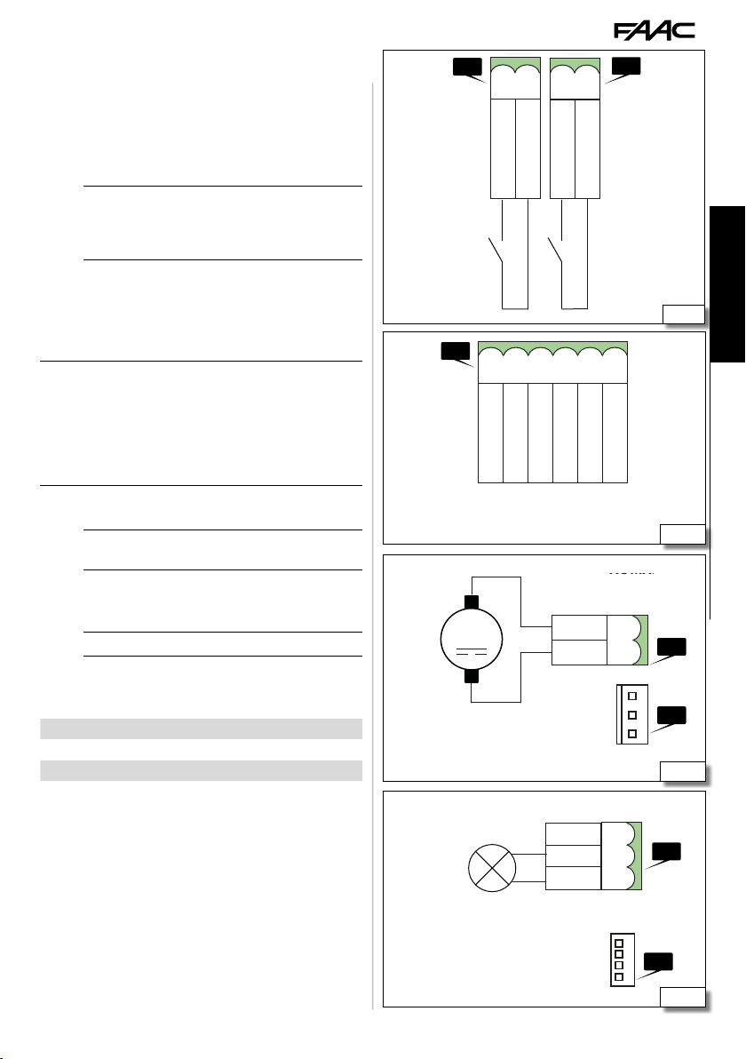
EXTERNAL LOOPS
The magnetic coil detectors must not be used to
!
detect pedestrians, cycles and motorbikes. If it is
not possible to prevent them passing, other devices
such as photocells are necessary.
(37) Connect the magnetic coil detectors to terminal boards J10 (LOOP 1) or J13 (LOOP 2).
LOOP 1
LOOP 2
BUS DEVICES
See § 9.4 for the connection and orientation.
OUT OUTPUTS
Open Collector Outputs: the activation of the output
and its polarity can be configured by Advanced programming.
NO polarity 0 V
NC polarity open circuit 0 V
(38) Connect the devices required to terminal
board J20.
24 V " FLASHING LIGHT
See § 9.1 for the connection.
MOTOR
(39) The motor wire is connected in the factory
for a RH barrier.
Invert the wires if a LH barrier is being installed.
ENCODER
The encoder wire is connected in the factory.
B614 35 732998 - Rev.A
Opening coil
NO contact, connect a detector that commands the
opening of the barrier when a contact is closed
Transit coil
NO contact, connect a detector that commands
the closure at the disengagement when a contact
is closed
The engagement of the loop during the closure
inverts the movement; the barrier cannot close as
long as the loop is engaged
If no BUS 2easy devices are used, leave the BUS 2easy
Li
terminal board free.
Respect the 100mA max load for each output.
Li
OUT active OUT not active
"
open circuit
"
J20
J10
red
M
blue
LOOP 1
GND
+24V
LOOP 2
LOOP 1
OUT 2
OUT 1
MOT
MOT
BLG
COM
BLR
LOOP 2
J3
OUT 3
BEAM
TRAFFIC
LAMP
J13
OUT 4
ENC
J18
J21
37
38
J23
J11
39
40
ENGLISH
Translation of the original instructions
Page 38
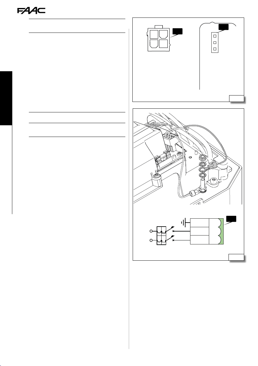
AC MAIN
XF 433-868
The encoder must always be connected in order for
Li
the automation system to operate.
BEAM LIGHTS
See § 9.5 and § 9.6 for the connection.
INTEGRATED FLASHING LIGHT
40 See § 9.6 for the connection.
XBAT 24 BATTERY
41 See § 9.2 for the connection.
XF RADIO MODULE
41 See § 9.3 for the activation.
MAINS SUPPLY AND EARTHING
ENGLISH
Use a 3G 1.5 mm2 wire (not supplied).
Li
The grounding between board and box is done in the
!
factory. Do not remove the connection.
1. Crimp the earth wire of the power cable to the
cable terminal provided.
2. (42) Insert 2 washers, the cable terminal and
the nut provided on the earth plug respecting the
insertion order.
3. Tighten the nut.
4. Connect the phase wires and neutral to J1.
J8
J7
41
Translation of the original instructions
6 A
N
L
PE
N
L
B614 36 732998 - Rev.A
J1
42
Page 39

7. STARTUP
-
+
-
-
RISKS
PERSONAL PROTECTIVE EQUIPMENT
During operation there is a risk of cutting, crushing
!
or the total loss of hands due to the moving parts
inside the box.
If two barriers are installed in the following configuration Master-Slave, before beginning the start up
of the Master, it is necessary to have configured the
Slave barrier (see § 10).
1. Check that the B614 is locked.
2. Power up the plant (Master barrier). The board
lights up and the display then comes on:
- firmware version (2 digits separated by a point)
SO flashing if a set-up or the automation status
is requested
3. Check the status of the LEDs at rest (see § 11.1).
The BUS 2easy LEDs must be checked after the devices
Li
have been registered.
4. Memorise the radio controls present on the plant
(sees § 9.3).
5. Program E614 without performing the set-up.
For the barrier to work properly, set the parameter
!
cF dependent on the beam length.
6. Register the BUS 2easy devices, if they are installed
(see § 9.4).
7. Check the barrier's direction of travel (see § 11.2).
8. Perform the set-up (see § 7.3).
9. If the XBAT 24 battery is being used:
- Cut off the plant's power supply
- Connect the XBAT 24 battery
- Switch on power to the system.
7.1 PROGRAMMING
BASIC PROGRAMMING
1. Press and hold down F until the first basic
function appears. (Each function is displayed
as long as F remains pressed).
F
2. Release: the value of the function appears
(default or programmed).
F
3. Use the + or - button to modify the value.
4. Press F to confirm the value displayed. Go
to the next function. The modified value
becomes effective immediately.
Proceed in the same way for all the functions. The last function
(
St) allows you to close the program.
St select Y or no using the +/
5. In
-
F
buttons:
Y = save the new program
no = DO NOT save the new program
6. Press F to confirm and close the program. It returns to the
automation status view.
To exit from the programming mode at
any time:
press and hold down F and then
move directly to
St.
-
as well to
+
F
ENGLISH
Translation of the original instructions
B614 37 732998 - Rev.A
Page 40

ADVANCED PROGRAMMING
F
+
+
-
+
-
-
1. Press and hold down F and then + as well,
until the first advanced function appears. (Each
function is displayed as long as F remains
pressed).
2. Release: the value of the function appears
(default or programmed).
ENGLISH
3. Use the + or - button to modify the value.
4. Press F to confirm the value displayed. Go
to the next function. The modified value
becomes effective immediately.
Proceed in the same way for all the functions. The last function
(
St) allows you to close the program.
St select Y or no using the +/
5. In
-
buttons:
+
+
F
Y = save the new program
no = DO NOT save the new program
Translation of the original instructions
6. Press F to confirm and close the program. It returns to the
automation status view.
To exit from the programming mode at
any time:
-
press and hold down F and then
move directly to
St.
as well to
+
8 Basic programming
Basic function Default
BARRIER CONFIGURATION
cF
Set functional parameters (including opening and
closing speed) dependent on the beam length.
03
01 beam up to 3m
02 beam from 3m to 4m
03 beam from 4m to 5m
DEFAULT
dF
Displayed if the board is configured with the
factory settings (default).
F
Y indicates that all set values correspond to
the defaults
Y
no indicates that one or more set values are
different from the defaults
Y if you wish to restore the default
Select
configuration.
MASTER/SLAVE configuration.
Ct
MA Configures the board in Mastermode
MA
SL Configures the board in Slavemode
The following parameters are not
Li
displayed on the Slave board:
LO-
PA-bu-tL- PF-t -bF. See the
relative section.
FUNCTIONING LOGIC
LO
EP Semi-automatic step by step
EP
A Automatic
AP Automatic step by step
b Semiautomatic B
bC Semiautomatic B on opening/person
present C on closure
C Person present
P Car park
See the dedicated section for the
Li
F
PA
functioning of the logics
PAUSE TIME
Adjustable from
If 59 is exceeded, the display changes to indicate
minutes and tens of seconds (separated by a dot)
and can be adjusted in steps of 10 seconds, up to
a maximum of 9.5 minutes.
00 a 59 s, to 1 sec steps.
20
E.g.: if the display indicates 2.5, the
Li
time is 2 min and 50 sec.
OPENING SPEED
So
01 minimum speed
10 maximum speed
CLOSURE SPEED
Sc
01 minimum speed
10 maximum speed
B614 38 732998 - Rev.A
See table
Default
speed
See table
Default
speed
Page 41

Basic function Default
BUS 2easy DEVICE REGISTRATION
bu
See the relative section.
Li
Dead-man MOTOR OPERATION mode
M1
+ OPENS (displaying oP) as long as the
button remains pressed.
-
CLOSES (displaying cL) as long as the
button remains pressed.
SET-UP
tL
Acquire the limit switch positions.
See the relative section.
Li
LEAVING THE PROGRAMMING MODE
St
Y save and exit from programming mode
no exit from programming mode without
saving
Press F to confirm. After exiting, the display
indicates the status of the automation system:
00 = Closed
01 = Open
02 = Stationary then opens
03 = Stationary then closes
04 = Pausing
05 = Opening
06 = Closing
07 = Failsafe in progress
08 = Check of BUS 2easy device in progress
09 = Pre-flashing and then opens
10 = Pre-flashing and then closes
11 = Opening in emergency
9 Default speed
no
--
no
Y
cF 01 cF 02 cF 03
10 06 02
So
08 04 02
Sc
10 Advanced programming
Advanced function Default
PRE-FLASHING
PF
no disabled
OC preflashing 3 sec. before each movement
DRIVING FORCE ON OPENING
FO
01 minimum power
50 maximum power
DRIVING FORCE ON CLOSURE
FC
01 minimum power
50 maximum power
STOP INPUT CONFIGURATION
SP
It defines the function of the STOP input
00 (STOP) Stop
02 (FSW-CL) Closure photoelectric cell
OPERATING TIME (time-out)
t
Set a higher value than the time the barrier needs
to open/close completely.
This can be regulated from 0 to 59 secs. in 1 sec
steps. Afterwards, the display changes in minutes
and tens of seconds (separated by a dot) and the
time is regulated in 10 sec. steps, up to a maximum
value of 9.5 minutes.
E.g.: if the display indicates
2 min and 50 sec.
In the case of a plant with a Master/
Li
Slave configuration an operating time
must be set on the Master central
control unit that takes account of the
movement of both the barriers.
OUT OUTPUT 1 CONFIGURATION
o1
00 Always active
01 failsafe
02 telltale light (on during opening/pause/
open, flashing on closure, off when closed)
03 courtesy light
05 barrier open or in pause mode
06 barrier closed
07 barrier moving
08 barrier in emergency mode
09 barrier opening
10 barrier closing
12 safety device active
13 light column (active in pause mode/open,
turns off on closure)
15 step by step activation through second radio
channel
19 battery operation
20 Loop1 engaged
21 Loop2 engaged
2.5, the pause time is
no
50
50
00
5.0
00
ENGLISH
Translation of the original instructions
B614 39 732998 - Rev.A
Page 42

Advanced function Default
OUT OUTPUT 1 POLARITY
P1
Y NC output
no NO output
o1 = 01 (Fail-safe) configure P1 = no.
If output
o2
see o1
P2
see P1
o3
see o1
P3
see P1
o4
see o1
P4
see P1
OUT OUTPUT 1 TIMING
ENGLISH
to
(only displayed if one of the outputs is configured as courtesy light)
This defines the timing of the output from 1 to 59
minutes in 1 minute steps.
BATTERY OPERATION
bF
01 continues to function until completely dead
02 the barrier opens when the mains power is
interrupted
03 the barrier closes when the mains power is
interrupted
INTEGRATED flashing light OPERATING MODE
oS
01 light column (steady green with barrier in
pause mode/open, red flashing during movement,
red steady with barrier closed)
02 flashing light (flashing red during move-
Translation of the original instructions
ment, off in all other states)
Advanced function Default
no
CYCLE PROGRAMMING IN HUNDREDS OF THOU-
nC
SANDS
This makes it possible to set a countdown of the
plant operating cycles from 0 to 99 (hundreds of
thousands of cycles). The value displayed is updated
a the cycles progress, integrating with the
(1
nC decease corresponds to 99 nc decreases).
The function can be used in combination with
nc, to verify plant use and for the "Request for
Assistance".
AUTOMATION SYSTEM STATUS:
St
St in the Basic programming
See
02
01
01
00
nc value.
Y
BEAM LIGHT OPERATIONAL MODE
bL
01 lights on with barrier closed, off with barrier
in pause mode/open, flashing during the movement
01
02 lights off with barrier in pause mode/open,
flashing in all other states
MAINTENANCE REQUEST - CYCLE COUNTER (linked
AS
to the next two functions)
This can be useful to set scheduled maintenance
interventions.
no
Y Active
no Excluded
CYCLE PROGRAMMING IN THOUSANDS
nc
This makes it possible to set a countdown of the
plant operating cycles from 0 to 99 (thousands of
cycles). The function can be used, in combination
nC, to verify the use of the system and for
with
the “Request for assistance”
00
00…99 (thousands of cycles)
B614 40 732998 - Rev.A
Page 43

7.2 OPERATING LOGICS
In all the logics:
Li
- the STOP command has the priority and stops the
automation system from working
- the STOP command has the priority and opens the
automation system.
EP SEMIAUTOMATIC STEP BY STEP
The EP logic requires the use of just the OPEN command:
- OPEN when the barrier is closed, it commands the
opening.
- OPEN when the barrier is open it commands the
closure.
- OPEN during the movement it stops
- OPEN after the stop, it reverses in movement.
The CLOSE command always commands the closure.
Li
A AUTOMATIC
Logic A only requires the OPEN command:
- OPEN when the barrier is closed, it commands the
opening. After the pause time, the barrier closes
again automatically.
- OPEN when the barrier is open in pause mode, it
reloads the pause time. (Even the intervention of
the photocells reloads the pause time)
- OPEN during opening is ignored.
- OPEN during opening causes it to open again.
The CLOSE command always commands the closure.
Li
AP AUTOMATIC STEPBYSTEP
The AP logic requires the use of just the OPEN command:
- OPEN when the barrier is closed, it commands the
opening. After the pause time, the barrier closes
again automatically.
- OPEN when the barrier is open in pause mode it
locks. (Even the intervention of the photocells
during the pause mode reloads the pause time)
- OPEN during the opening locks.
- OPEN during opening causes it to open again.
The CLOSE command always commands the closure.
Li
- OPEN during opening causes it to open again.
bC SEMIAUTOMATIC b ON OPENING/ PERSON
PRESENT
C ON CLOSURE
bC logic requires the use of the OPEN jog command
on opening and CLOSE maintained on closure. The
activation of the CLOSE command on closure must be
intentional and the barrier must be visible.
- OPEN when the barrier is closed, it commands the
opening.
- Maintained CLOSE commands the closure.
C DEADMAN
Logic C requires the use of maintained OPEN and
CLOSE commands. The control must be activated
intentionally and the barrier must be visible.
- Maintained OPEN commands the opening.
- Maintained CLOSE commands the closure.
- If the photocells are triggered, movement is
stopped.
P CAR PARK
Logic P requires the use of the OPEN and CLOSE
commands:
- OPEN when the barrier is closed, it commands the
opening.
- CLOSE when the barrier is open it commands the
closure.
- CLOSE during opening it causes reclosure after
opening.
- OPEN during opening causes it to open again.
- The triggering of the photocells during closure
stops the movement, on disengagement the barrier
continues to close.
ENGLISH
Translation of the original instructions
b SEMIAUTOMATIC B
Logic b requires the use of the OPEN and CLOSE
commands:
- OPEN when the barrier is closed, it commands the
opening.
- CLOSE when the barrier is open it commands the
closure.
- CLOSE during opening it causes reclosure.
B614 41 732998 - Rev.A
Page 44

7.3 SETUP
The set-up procedure enables the limit switch positions to be memorised.
The system needs to be set-up:
- When the automation system is first started
- When the board has been replaced
- Each time the display shows
automation system does not work
- Following any variation in the position of the limit
switch.
How to perform the set-up:
During the SET-UP, the safety devices are ignored,
!
ENGLISH
Translation of the original instructions
keep away and stop anyone from approaching the
automation system until the end of the procedure
The SET-UP MUST be performed:
Li
- with the mains power switched on
- with the automation system functioning automatically
- with the STOP/EMER inputs not active
1. Select parameter
display shows
2. Keep the buttons pressed
seconds. When
buttons. The beam begins to close and stops
when it reaches the stop.
flashes on the display. The beam remains in
S2
3.
the closure position for a couple of seconds.
S3 flashes on the display. The beam begins to
4.
open and stops when it reaches the stop.
5. The procedure has come to an end and the display
shows the status of the open automation system
01).
(
tL in Basic Programming, the
--.:
S1 appears flashing, release the
50 flashing and the
-
+ and
around 3
B614 42 732998 - Rev.A
Page 45

8. PUTTING INTO SERVICE
8.1 FINAL CHECKS
1. If foot traffic cannot be excluded, check that the
forces generated by the beam fall within the limits
permitted by the standard. Use an impact force
tester in accordance with standards EN 12453 and
EN 12445. For non-EU countries, of there are no
specific local regulations, the force must be less
than 150 N. Check that the maximum force required to move the beam by hand is less than 220 N.
2. Check the automation system is working properly
with all the devices installed.
8.2 FINAL OPERATIONS
1. Fit the upper cover (see the relative section).
2. (43) Apply the notice supplied warning
against the risk of cutting, crushing or the loss of
fingers or a hand between the beam and the body
of the barrier.
The indication of the RISK must be visible even with
!
the beam closed.
3. Highlight all areas with adequate warning signs
in which there are still residual risks, even if all
possible safety measures having been adopted.
4. Exhibit the sign prohibiting foot traffic.
5. Place the "DANGER - AUTOMATIC MOVEMENT" sign
where it is clearly visible. Place the EC marking
on the barrier.
Use adhesive signs so as not to perforate the box.
!
6. Fill out the EC declaration of conformity and the
system register.
7. Give the EC Declaration, the system register with
the maintenance plan and the instructions for use
of the automation to the system owner/operator.
ENGLISH
43
Translation of the original instructions
B614 43 732998 - Rev.A
Page 46

XF 433-868
9. ACCESSORIES
The installation must comply with Standards
!
EN 12453 and EN 12445.
When working in the box there are risks of cutting,
shearing, crushing hands due to the presence of
moving parts. Until the installation is completed,
the partially installed barrier must always be left
blocked and with the door and upper lid always
closed to prevent access to the electronic parts and
the moving mechanical pars.
Never install the beam before fixing the barrier body
and checking it. Until the installation is complete
never leave the barrier unguarded with the beam
fitted. Mark off the work site and prohibit access/
ENGLISH
Translation of the original instructions
transit. If installation is outside, it must be done in
good weather without rain or gusts of wind. If it is
raining, an adequate shelter for the barrier must be
made until the mechanical and electronic installation
is complete.
Never manage the barrier by holding the board holder.
9.1 24V " FLASHING LIGHT
The flashing light indicates that the automation is
moving.
Install the flashing light in an easily visible position.
Li
1. (44) Connect the flashing light to terminal
clamp J16 (3 W max).
2. If required, set the preflash (
gramming)
3. Check that the device is working properly.
9.2 XBAT 24 EMERGENCY BATTERY
The XBAT 24 provides power to the automation system
in the event of a mains power supply failure. The
number of cycles that can be carried out with the
battery depends on various factors (state of battery
charge, time elapsing since the power outage, room
temperature etc.).
1. (45) Positioning the battery
2. Connect the battery to clamp J8 on the board
3. Set battery operation (
Recharge the battery before starting the system. The
!
full charging cycle of the XBAT 24 battery is 72 hours.
ming)
Disconnect the emergency battery if the automation
Li
system is taken out of use.
PF Advanced pro-
bF Advanced program-
LAMP
LAMP
J16
44
B614 44 732998 - Rev.A
45
Page 47

9.3 XF RADIO MODULE
The E614 is fitted with an OMNIDEC integrated two
channel decoding system that can memorise, via the
XF radio module, FAAC radio controls that use the
following types of radio code: SLH/SLH LR, LC/RC, DS.
The three types of radio codes can coexist simulta-
Li
neously.
A maximum of 256 codes can be memorised.
The codes memorised act as an OPEN or CLOSE
command.
The radio controls and the XF radio module must have
the same frequency.
When memorising the codes, keep the radio control
approximately one meter from the XF radio module.
1. (46) Insert the XF radio module in the connector J3 paying attention to the insertion direction.
2. Memorise the radio controls.
Ensure that there are no obstacles (persons or things)
!
while the automation is moving.
SLH/SLH LR MEMORISING THE FIRST RADIO
CONTROL
1. Press and keep pressed the + key (OPEN programming) or - (CLOSE programming). After pressing
the button for about 5 seconds, the corresponding
radio LED (DL4 or DL5) will start to flash to indicate
that the radio code learning phase has started.
2. Release the button. From this moment E614
stays in the learning phase for around 20 secs.
3. Press and hold down buttons P1 and P2 simultaneously on the SLH/SLH LR radio control (master
version only). The LED on the radio control starts
to flash.
4. Release both buttons; the LED on the radio control
continues to flash.
5. Make sure that the LED DL4 or DL5 on the board is
still flashing and press the button of the radio control that you wish to memorise for a few seconds
(the LED becomes steady). Release the button of
the radio control.
6. Press the same button that was used in the
previous step twice in succession to complete
the memorisation process. If the procedure
was carried out correctly, the B614 will open the
beam, if permitted by the operating mode that
has been set.
SLH/SLH LR MEMORISING OTHER RADIO
CONTROLS
1. Press and hold down buttons P1 and P2 simultaneously on the SLH/SLH LR radio control that
has already been memorised (master version
only). The LED on the radio control starts to flash.
2. Release both buttons; the LED on the radio control
B614 45 732998 - Rev.A
continues to flash.
3. Press and hold down the button that has already
been memorised (the LED becomes steady).
4. Place the remote control that has already been
memorised close to the remote control to be
memorised (keeping the button in the previous
step pressed).
5. Press the button of the radio control to be memorised and make sure that its LED flashes twice
before going off, to indicate that the procedure
was completed successfully.
6. Release all buttons.
7. Press the button used in step 5 twice in succession
to complete the memorisation process for the new
radio control. If the procedure was carried out
correctly, the B614 will open the beam, if permitted
by the operating mode that has been set.
LC/RC MEMORISING THE FIRST RADIO
CONTROL
1. Press and keep pressed the + key (OPEN programming) or - (CLOSE programming). After pressing
the button for about 5 seconds, the corresponding
radio LED (DL4 or DL5) will start to flash to indicate
that the radio code learning phase has started.
2. Release the button, from this moment E614 stays
in the learning phase for around 20 secs.
3. Make sure that the LED DL4 or DL5 on the board
is still flashing and press the button of the LC/RC
radio control that you wish to memorise for a few
seconds (the LED becomes steady). The LED
(DL4 or DL5) on the board goes on as a steady light
for 1 sec to then start flashing again for another 20
seconds during which it is possible to memorise
another radio control.
4. To memorise additional radio controls at a later stage,
ENGLISH
46
Translation of the original instructions
Page 48

repeat the procedure from the beginning or carry
out the remote memorisation procedure.
LC/RC REMOTE CODE MEMORISATION
PROCEDURE
Additional radio controls can be memorised remotely,
i.e. without having to use the board directly, by using a
radio control that has already been memorised.
1. Near the E614 press buttons P1 and P2 if the radio
control already memorised (as OPEN or CLOSE at
the same time). The LED of the radio control
and LED DL4 or DL5 of the board begin to flash
for 5 secs.
2. Release both the buttons then press the button
already memorised within five seconds. From
this moment E614 stays in the learning phase for
ENGLISH
around 20 secs.
3. Make sure that the LED DL4 or DL5 on the board
is still flashing and press the button of the radio
control that you wish to memorise. The LED (DL4
or DL5) on the board goes on as a steady light for
2 sec to then start flashing again for another 20
seconds during which it is possible to memorise
another radio control.
4. Wait for LED DL4 or DL5 on the board to turn off
before using the new radio control.
DS MEMORISING RADIO CONTROLS
1. Set the required ON/OFF combination of the 12
dip-switches on the DS radio control. Avoid setting
all of them to ON or all of them to OFF.
2. Press and keep pressed the + key (OPEN programming) or - (CLOSE programming). After pressing
Translation of the original instructions
the button for about 5 seconds, the corresponding
radio LED (DL4 or DL5) will start to flash to indicate
that the radio code learning phase has started.
3. Release the button, from this moment E614 stays
in the learning phase for around 20 secs.
4. Make sure that the LED DL4 or DL5 on the board is
still flashing and press the button of the DS radio
control that you wish to memorise for a few seconds. The corresponding LED (DL4 or DL5) on the
board will turn on with a steady light for 1 second
and then turn off to indicate that the procedure
was completed successfully.
5. To add different codes, repeat the procedure starting from point 1.
6. For additional radio controls, use the same ON/OFF
combination for the 12 DIP switches on the radio
control that has been memorised.
DELETING RADIO CONTROLS FROM MEMORY
This procedure cannot be reversed and cancels ALL the
!
codes of the radio controls memorised both as OPEN
and as CLOSE. The deletion procedure is only active
in the barrier status display mode.
1. Press and hold down the - button.
- After holding LED DL5 down for approx 5 seconds
it begins to flash slowly, after another 5 seconds
flashing slowly and pressure maintained LEDs DL4
and DL5 begin to flash more quickly (beginning
cancellation).
- At the end of the rapid flashing LEDs DL4 and
DL5 come on and remain steady to confirm the
successful cancellation of all the (OPEN and CLOSE)
radio codes in the board.
2. Release the - button. The LEDs turn
off, indicating that the codes were
deleted correctly.
-
-
B614 46 732998 - Rev.A
Page 49
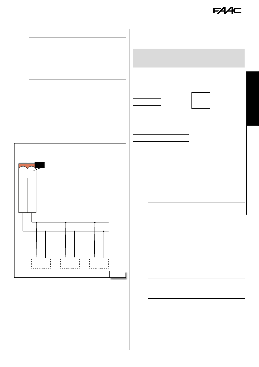
GND
LAMP
OUT 4
OUT 3
OUT 2
OUT 1
+24V
LAMP
XF 433-868
9.4 BUS 2EASY DEVICES
This board has a BUS 2easy circuit for connecting
BUS 2easy devices (photocells, control devices).
If no BUS 2easy accessories are used, leave the
Li
BUS 2easy connector free. Do not bridge.
CONNECTION
(47) Connecting any devices BUS 2easy (photocells and command devices) to terminal J3.
The overall length of the BUS 2easy cables must not
Li
exceed 100 m.
The BUS line does not require a matching polarity
connection.
J3
BUS
BUS
BUS BUS BUS
47
BUS 2EASY PHOTOCELLS
Type of use:
Closing photocells
Photocells
used as pulse
generators
1. Assign an address to the BUS 2easy photocells.
11 Orienting the photocells
1 0 0 0
1 0 0 1
1 0 1 0
1 0 1 1
1 1 0 0
1 1 1 0
1 1 1 1 OPEN
Assign an address to each pair of photocells by setting
the four DIP switches (DS1) on the transmitter and the
corresponding receiver.
2. Register the BUS 2easy photocells (
gramming).
3. Check the status of LEDs DL3 and DL7 ( ).
4. Check that the photocells are operating correctly. When the beam is moving, interrupt it with
an obstacle and check the LEDs on the photocells,
the status of the bus on the display and the automation system operate according to the type of
photocell installed.
CONTROL DEVICES
1. Position the DIP switches to assign the commands.
Active during
closing
Always active When an obstacle is de-
CL FSW
The transmitter and receiver of a pair of photocells
Li
must have the same DIP switch settings.
There must never be two or more pairs of photocells
with the same DIP switch settings. If there is more
than one pair of photocells with the same address, a
conflict error is generated.
When an obstacle is detected, they stop the beam
and reopen it.
tected, they send an OPEN
command
ON
1 2 3 4
bu Basic pro-
Stop NC also generates a stop when the device is
Li
disconnected. A command (e.g.: OPEN A_1) must
be used on only one of the connected devices.
ENGLISH
Translation of the original instructions
B614 47 732998 - Rev.A
Page 50

12 Addressing control devices
0 0 0 0 Open A_1
0 0 0 1 Open A_2
0 0 1 0 Open A_3
0 0 1 1 Open A_4
0 1 0 0 Open A_5
0 1 0 1 Stop
0 1 1 0 Stop NC_1
0 1 1 1 Stop NC_2
1 0 0 0 Close
1 0 0 1 Open B_1
1 0 1 0 Open B_2
1 0 1 1 Open B_3
ENGLISH
1 1 0 0 Open B_4
1 1 0 1 Open B_5
1 1 1 0 /
1 1 1 1 /
0 0 0 0 Open A_1 Open B_1
0 0 0 1 Open A_1 Open B_2
0 0 1 0 Open A_1 Stop
0 0 1 1 Open A_1 Close
0 1 0 0 Open A_2 Open B_1
0 1 0 1 Open A_2 Open B_2
0 1 1 0 Open A_2 Stop
0 1 1 1 Open A_2 Close
1 0 0 0 Open A_3 Open B_3
Translation of the original instructions
1 0 0 1 Open A_3 Open B_4
1 0 1 0 Open A_3 StopNC_1
1 0 1 1 Open A_3 Close
1 1 0 0 Open A_4 Open B_3
1 1 0 1 Open A_4 Open B_4
1 1 1 0 Open A_4 StopNC_2
1 1 1 1 Open A_4 Close
2. Register the BUS 2easy control devices (
programming).
3. Check the status of LEDs DL3 and DL7 ( ).
4. Check that the devices are working properly. Use
the controls to make the beam move. Check the
LEDs on the devices, the status of the bus on the
display and make sure that the automation system
operates according to the type of device installed.
BUS 2EASY DEVICE REGISTRATION
Registration is required:
- When the automation system is first started or after
the board has been replaced.
- Following any changes (addition, replacement or
removal) to the BUS 2easy devices.
ON
1 2 3 4 5
1 command
DIP switch 5 = 0 (OFF)
ON
1 2 3 4 5
2 commands
DIP switch 5 = 1 (ON)
bu Basic
Registration procedure:
1. Selec t parameter
bu in basic programming. When
F is released, the display shows the status of the
BUS 2easy devices ().
2. Press and hold the
for at least 5 seconds until
flashes during this time). Registration has been
completed.
3. Release the
the status of the BUS 2easy devices
4. Check the status of the LEDs on the board:
LED DL7 (Red) - BUS 2easy devices
LED DL3 (Green) - BUS 2easy line
Registered device verification procedure:
1. Select parameter
registering one or more devices,
segment 13 on.
2. Press and hold the
the segments relative to the registered devices
will come on. Each segment of the display corresponds to a type of device:
1 Open A control device
2 Open B control device
3 Closing photocells
4 Photocells for Open impulse
5 Not used
6 Close control device
7 Not used
8 Stop control device
9 Closing edge
10 Not used
11 Not used
12 Opening edge
13 BUS 2easy status
14 Not used
+ and
At least one device is engaged/active
No device is engaged/active
Line monitoring. LED always on (off with board in Sleep
mode)
Line short-circuited
Device error: check the ERROR LED
-
+ and
buttons simultaneously
Y appears (the display
-
buttons. The display shows
bu in basic programming. After
bu displays
+ button and keep it pressed;
B614 48 732998 - Rev.A
Page 51

147 6 8
1
2
12
135
11
8. 8.
103 4 9
No device registered
no
BUS 2easy line short-circuited
cc
BUS 2easy line error
Er
RECTANGULAR BEAM LIGHT KIT
Follow the assembly instructions provided with the
product respecting all the safety precautions indicated
in this manual.
9.5 ROUND BEAM LIGHT KIT
Follow the assembly instructions provided with the
product respecting all the safety precautions indicated
in this manual.
9.6 INTEGRATED FLASHING LIGHT
1. Open the upper cover.
2. Fasten the flashing light with the screws provided
(48).
3. Connect the flashing light to terminal J21.
4. Set the operating mode (
gramming).
5. Close the upper cover.
6. Check that the device is working properly.
oS in Advanced pro-
ENGLISH
48
Translation of the original instructions
9.7 BEAM JOINT KIT
Follow the assembly instructions provided with the
product respecting all the safety precautions indicated
in this manual.
The installation of a jointed beam must take the
!
specific risks into consideration:
- IMPACT on the horizontal section of the beam,
when the beam is open
- CRUSHING in the jointed area, when the beam
is moving.
- Do not use joint to limit the height of the vehicles
passing.
- Indicate the maximum height of the vehicles considering the height of the beam itself.
- Apply a danger of crushing sticker on the beam in
the jointed area.
- Check the integrity of the wire during the half-yearly
scheduled maintenance.
B614 49 732998 - Rev.A
Page 52

9.8 HEDGE
Follow the assembly instructions provided with the
product respecting all the safety precautions indicated
in this manual.
Check the fixing with the indicated tightening torque.
!
9.9 FOOT
Follow the assembly instructions provided with the
product respecting all the safety precautions indicated
in this manual.
- Check the fixing with the indicated tightening
!
torque.
- Check the lower protection is present and is in
ENGLISH
Translation of the original instructions
good condition.
- You should install a beeper or similar to indicate
the beam is closing.
- Apply the reflector on the stem.
On the rectangular beam, it is not possible to install
Li
the foot when there are lights on the beam.
9.10 FORK
Follow the assembly instructions provided with the
product respecting all the safety precautions indicated
in this manual.
- Check the fixing with the indicated tightening
!
torque.
- You should install a beeper or similar to indicate
the beam is closing.
- Provide for a clearance area or signals to prevent
pedestrians being knocked. The area must be
adequately lit.
Adjustable foot
1
Hedge kit
3
XF
5
Adjustable fork
2
Beam light kit
4
XBAT 24
6
Head light kit
7 8
B614 50 732998 - Rev.A
Joint kit
Page 53
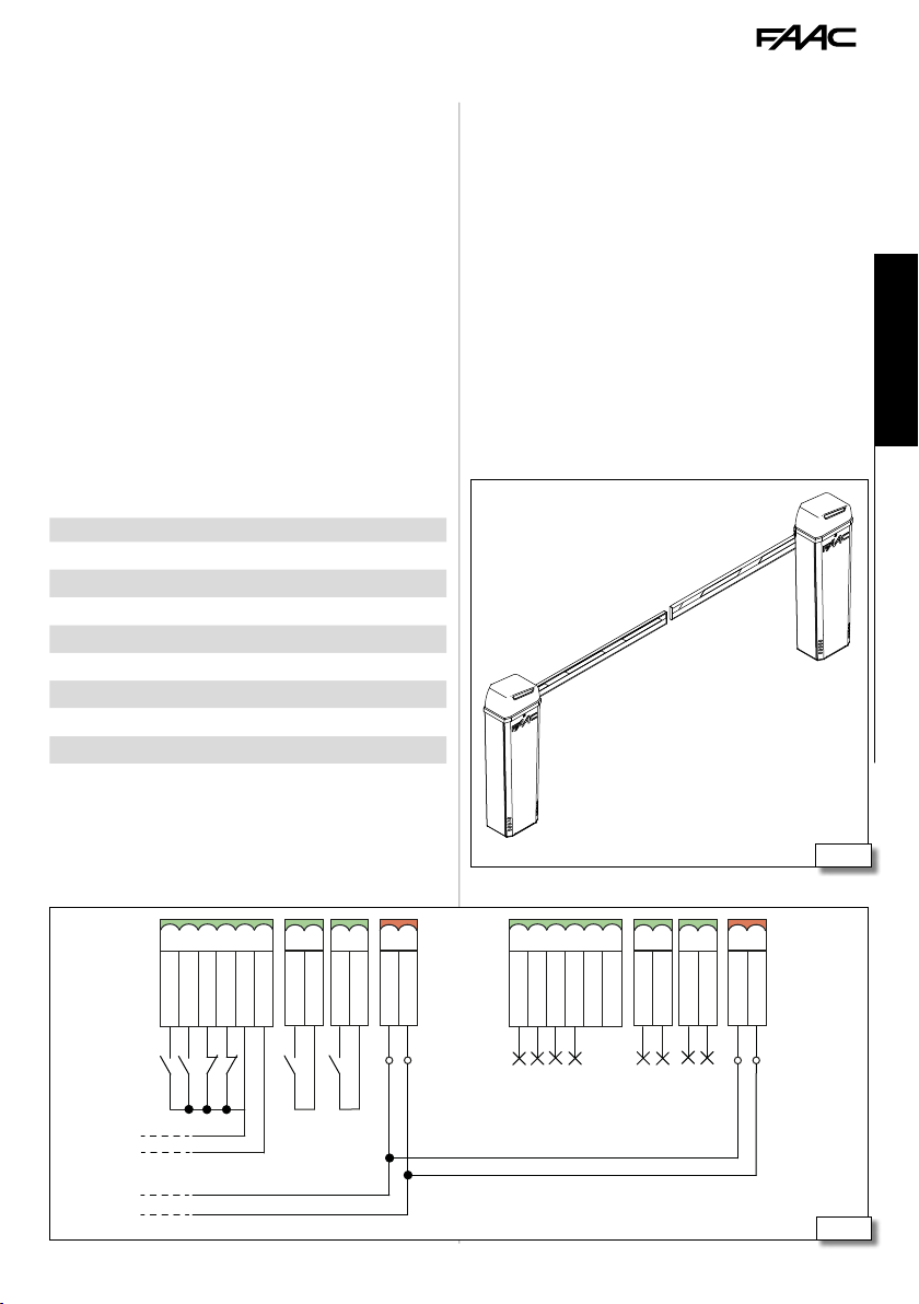
L
10. MASTERSLAVE
(49) The Master-Slave configuration makes it
possible to install two counterposed barriers with
synchronous movement.
When programming one barrier must be defined as
Master and the other as Slave. The Master barrier
manages all the controls and movements.
The control devices and any external loops must be
connected to the Master barrier.
Each barrier must be programmed on the basis of the
length and configuration of the beam. The functioning logic must only be programmed on the Master
board. The anticrushing function is active on each
barrier and commands the inversion of both.
CONNECTION
1. Connect the barrier with BUS 2easy polarised
connection 50).
2. Connect the devices (see § 6.2). The inputs for
the command devices and any external loop are
inhibited on the Slave board.
Connections Master Slave
Power supply
Motor
Encoder
Head lighting
Beam lights
Control devices
Loop
Outputs
Flashing light
3. The BUS 2easy devices can be connected to the
Master or to the Slave board. The devices must be
registered on the Master barrier.
ENGLISH
Translation of the original instructions
49
1
2
345
6
OPEN
CLOSE
B614 51 732998 - Rev.A
STOP
GND
EMER
+24V
LOOP 1
LOOP 1
LOOP 2
LOOP 2
BUS
1
BUS
2
1
OPEN
2
CLOSE
345
EMER
STOP
GND
6
+24V
LOOP 1
LOOP 1
LOOP 2
LOOP 2
BUS
1
BUS
2
50
Page 54

SLAVE BARRIER CONFIGURATION
1. Power Slave barrier The board turns on. The
display reads in sequence:
- firmware version (2 digits separated by a point)
SO flashing if a set-up or the automation status
is requested
2. Access the Basic programming and set:
cF depending on the beam configuration and
length
Ct=SL for configuring the board as Slave.
-
3. Check the status of the LEDs on the board:
LED DL7 (Red)
Master-Slave synchronisation absent or the line
ENGLISH
LED DL3 (Green)
4. Check the direction of travel (see § 11.2). The
barrier must not be in manual functioning mode.
5. Start up (see § 7).
is short circuited.
Master-Slave synchronisation present.
During the set-up the Master board controls the Slave
Li
board and the two beams move with a synchronous
movement.
Translation of the original instructions
B614 52 732998 - Rev.A
Page 55

11. DIAGNOSTICS
11.1 LEDS CHECK
LED STATUS IDLE
DL1 BUS
DL2 BUS MON See BUS 2easy device
DL3 RADIO1
DL4 RADIO2
DL5 Error/alarm “ERROR”
DL8 EMER
DL9 STOP
DL10 CLOSE
DL11 OPEN
DL12 LOOP1
DL13 LOOP2
In Master-Slave configuration see § 10.
Li
11.2 DIRECTION OF MOVEMENT CHECK
1. Select parameter M1 in the Basic programming. The display shows
2. Keep the + button pressed. The display shows
oP and the barrier opens.
-
3. Keep the
button pressed. The display shows
cL and the barrier closes.
4. If the conditions in points 2 and 3 are not respected, invert the motor wires.
11.3 ENCODER OPERATION CHECK
1. Select parameter M1 in Basic Programming, the
display shows
2. Keep the + button pressed. The display shows
oP and the barrier opens. The flashing point
between the two letters indicates that the encoder
is operating correctly.
3. Keep the
-
button pressed. The display shows
cL and the barrier closes. The flashing point
between the two letters indicates that the encoder
is operating correctly.
--.
active
not active
registration
active
not active
active
not active
active
not active
not active
active
not active
active
active
not active
active
not active
active
not active
--.
11.4 AUTOMATION SYSTEM STATUS CHECK
The E614 display if not in the programming, shows a
code indicating the status the automation is in:
Closed
00
Open
01
Stationary then opens
02
Stationary then closes
03
In pause mode
04
Opening
05
Closing
06
Failsafe in progress
07
BUS 2easy device verification in progress
08
Pre-flashing and then opens
09
Pre-flashing and then closes
10
Opening in Emergency
11
11.5 CHECK FIRMWARE VERSION
When the display of the E614 is switched on, it shows
the following in succession:
- firmware version (2 digits separated by a point)
- automation system status
11.6 CHECK OF THE REGISTERED BUS 2EASY DEVICES
1. Select parameter bu in Basic programming.
2. Press and hold the
to the registered devices will light up (see 48).
+ button; the segments relative
ENGLISH
Translation of the original instructions
B614 53 732998 - Rev.A
Page 56

12. MAINTENANCE
RISKS
PERSONAL PROTECTIVE EQUIPMENT
Always shut off the power supply before performing
F
any maintenance operations. If the disconnect
switch is not in view, apply a warning sign stating
ENGLISH
Translation of the original instructions
“WARNING - Maintenance in Progress”. Restore the
power supply only after finishing any maintenance
work and restoring the area to normal.
Do not remove the board cover. No maintenance
requires the removal of the cover.
The barrier must not be left released. If the barrier
!
is put out of order for a long time, the beam needs
to be removed.
Maintenance must be performed by the installer or a
maintenance technician.
Follow all safety recommendations and instructions
given in this manual.
Mark off the work site and prohibit access/transit. Do
not leave the work site unattended.
The work area must be kept tidy and cleared after
maintenance has been completed.
Before starting work, wait for any hot components
to cool down.
Do not make any modifications to the original
components.
FAAC S.p.A. shall bear no liability for damage or
injury due to components that have been modified
or otherwise tampered with.
The warranty shall be forfeited in the event of tam-
Li
pering with components.
Only use original FAAC spare parts.
12.1 ROUTINE MAINTENANCE
The Scheduled maintenance lists, purely for guidance
which is not intended to be exhaustive, the operations
which must be performed on a regular basis to keep
the automation system safe and in good working
order. The installer/machine manufacturer is responsible for drawing up the maintenance plan for
the automation, supplementing this list or modifying
the maintenance intervals according to the machine
characteristics.
13 Routine maintenance
If the tests listed below turn up conditions that are
other than expected, repair or restoration is necessary. The plant must not be put back into operation
until all the safety precautions specified in this manual
and in the documentation of all the other components
installed have been complied with.
Operations Frequency/months
Structures
Check the plinth and built/fenced parts around the automation system: make sure there is no damage, cracking, breaks
or subsidence.
Check the area the beam moves in: make sure there are no
objects/deposits that reduce the uncluttered safety areas and
obstacles to the movement of the beam such as branches,
overhead wires etc.
Ensure that there are no sharp protrusions which could
represent a perforation or hooking hazard.
Barrier
Check the fixing of the bearing box to the foundation plate. 6
Check the barrier and its fixings: integrity, absence of defor-
mation, rust etc.
Check that screws and bolts are correctly tightened.
Check the condition of the beam and that it is fastened
properly.
Check the condition of the beam and that it is fastened
properly.
Check the presence and integrity of the reflectors on the beam
and all the other signs and markings necessary.
Check the integrity and proper fixing of the spring and tie
rods.
Check the configuration and the balancing of the barrier. 12
Check the integrity, proper functioning and adjustment of
the limit switch.
Check the integrity of all the cables, cable glands and
junction boxes.
Check that it is irreversible. 12
12
12
12
12
12
12
6
12
12
12
B614 54 732998 - Rev.A
Page 57

Clean the gearmotor and the bearing box. 12
Do a general cleaning of the barrier manoeuvre area. 12
Electronic equipment
Check the integrity of the upper cover and the plastic electronic board protection.
Check that the connectors and wiring are intact. 12
Check that the earth connections are intact. 12
Check that there are no signs of overheating, burning etc. of
electronic components.
Check the operation of the circuit breaker and differential
switch.
Control devices
Check that the installed devices and radio controls are in good
condition and that they operate correctly.
Deformable edges
Check that they are intact and correctly fastened. 12
Photocells
Check condition, fastening and correct operation. 6
Check the posts, ensuring that they are intact, correctly
fastened and free of deformation etc.
Flashing light
Check condition, fastening and correct operation. 12
Access control
Check the proper opening of the barrier only with authorised
user recognition.
Hedge
Check: the integrity and fixing of the beam. 6
Foot
Check: the integrity and fixing of the beam. 6
Check the presence and integrity of the reflectors on the foot
and all the other signs and markings necessary.
Check the presence and integrity of the lower foot guard. 6
Fork
Check that they are intact and correctly fastened. 6
Check the presence and integrity of all the signs and markings
necessary.
Jointed beam
Check that they are intact and correctly fastened. 6
Check the integrity of the wire and the relative signs (max
height allowed, risk of crushing in the beam joint).
Complete automation system
Check that the automation operates correctly, following the
set logic, when using the various control devices.
Check the proper fluid, smooth movement of the beam
without strange noises.
Check the correct speed during opening and closing and the
respect for the intended slow downs.
Check the correct functioning of the manual release: when
the release is activated it must only be possible to move the
beam manually.
Check the presence of the lock cover.
12
Check that the maximum force required to move the beam
by hand is less than 220 N.
Check that the encoder is working properly. 6
Check that each pair of photocells is working correctly. 6
12
Check there is no optical/light interference between the
photocells.
12
If the pedestrian transit cannot be excluded, check the force
limitation curve (EN 12453 and EN 12445 standards). For
non-EU countries, of there are no specific local regulations,
the force must be less than 150 N. ??
12
Check that all necessary signage and warnings are present,
intact and legible: residual risks, exclusive use etc.
Check the presence, integrity, legibility of the EC marking
covering the automation system and the DANGER AUTOMATIC
MOVEMENT warning sign
6
12
6
6
6
12
12
6
6
6
6
12
12
ENGLISH
Translation of the original instructions
B614 55 732998 - Rev.A
Page 58

14 Periodic replacements
Component Work cycle periodicity
Spring 200000
Electromechanical gearmotor 500000
12.2 SPRING REPLACEMENT
1. Perform the release manoeuvre.
2. Lift the beam completely vertically.
3. Restore the automatic operation.
4. Lengthen the turnbuckle by manually unscrewing
it to facilitate the operation.
5. Unhook the spring from the turnbuckle and the
slot on the bottom of the barrier body
6. Replace the spring
7. Balance the beam
ENGLISH
12.3 REPLACING THE GEARMOTOR
1. Perform the release manoeuvre.
2. Lift the beam completely vertically.
3. Restore the automatic operation.
4. Lengthen the turnbuckle by manually unscrewing
it to facilitate the operation.
5. Unhook the spring from the turnbuckle and the
slot on the bottom of the barrier body.
6. Perform the release manoeuvre and bring the
beam into the horizontal position.
7. Remove the beam.
8. Position the balancer as shown in the figure.
9. Restore Automatic Operation.
10. Remove the seeger ring on the drive shaft.
11. Unscrew the 4 nuts and remove the washers.
Translation of the original instructions
12. Remove the gearmotor
13. Remove the electric motor, taking care not to
damage its cable.
14. Install the electric motor onto the new gearmotor
and follow the procedure in reverse.
51
B614 56 732998 - Rev.A
Page 59

12.4 FUSE REPLACEMENT
1. (52) Remove the fuse F1 cover by gently pri-
sing it off with a screwdriver.
2. Dismantle the fuse
3. Assemble the new fuse.
4. Refit the fuse cover.
Only use a T 2.5A (delayed) fuse.
!
12.5 OPERATIONAL PROBLEMS
15 Troubleshooting
CONDITION FINDING SOLUTIONS
The barrier does not perform the SET-UP
The barrier does NOT
OPEN
The barrier CLOSES rather
than OPENING and vice
versa.
The barrier makes very
slow movements
The barrier does NOT
OPEN
The barrier does NOT
CLOSE
The barrier does NOT
OPEN and does NOT
CLOSE
check the automation is not released
check there is power
check the motor and encoder connection
invert the phases in the motor connection and perform a SET-UP
check the force set
check the balancing of the beam
check the parameter
in accordance with the beam length
if the barrier is being battery operated
make sure the battery is charged.
check the automation is not released
check the motor direction of travel
check the automation is not released
check the motor direction of travel
Check the LED status of the controls,
loops, safety devices and EMER are
not active
check the automation is not released
Check the status of the STOP LED is
not active
check the motor and encoder connection
52
ENGLISH
cF has been set
Translation of the original instructions
B614 57 732998 - Rev.A
Page 60

13. INSTRUCTIONS FOR USE
It is the responsibility of the machine installer/
manufacturer to draft the user instructions of the automation in accordance with the Machinery Directive,
including all the required information and instructions
based on the characteristics of the automation.
The guidelines below, which are purely indicative and
in no way exhaustive, help the installer draft the user
instructions.
The installer must provide the owner/operator of
!
the automation with the EC Declaration, the system
Logbook with the maintenance schedule and the user
instructions of the automation.
ENGLISH
The installer must inform the owner/operator of any
residual risks and the intended use and ways in which
the machine should not be used.
The owner is responsible for operating the automation and must:
- comply with all User instructions provided by the
installer/maintenance technician and the Safety
recommendations
- keep the user instructions
- have the maintenance schedule implemented
- keep the system Logbook, which must be completed by the maintenance technician at the end of
all servicing
unless they are supervised by an adult who is responsible for their safety.
- Do not use the automation in the presence of faults
which could compromise safety.
- Do not expose the automation system to corrosive
chemical or atmospheric agents; do not expose the
automation to water jets of any type or size.
- Do not perform any work on the components of
the automation.
Risk of cutting, crushing or losing fingers or a hand
between the beam and the box. Do not approach
the barrier, do not put your hands in the danger area
during movement.
13.2 EMERGENCY USE
Translation of the original instructions
13.1 SAFETY RECOMMENDATIONS
The plants made with FAAC buried actuators B614
series are intended for vehicular traffic.
The user must be in good physical and mental health
and be aware of and responsible for the dangers which
use of the product can lead to.
- Do not use the automation when the area of opera-
!
tion is not free of persons, animals or objects.
- Do not remain in or walk/drive through the area
of operation of the automation while it is moving.
- Do not allow children to approach or play in the area
of operation of the automation.
- Do not try to prevent the movement of the automation.
Do not climb or catch on to the beam or let yourself
be pulled by it.
- Do not allow the devices to be used by anyone who
is not specifically authorised and trained to do so.
- Do not allow the devices to be controlled by children
or persons with mental and physical deficiencies
B614 58 732998 - Rev.A
In emergencies or if there is a fault, turn off the power
supply to the automation and disconnect the buffer
batteries if there are any. If the beam can be moved
safely by hand, use the MANUAL OPERATION mode;
otherwise place the automation out of service until it
has been reset/repaired.
In the case of a breakdown, the automation must be
reset/repaired exclusively by the installer/maintenance
technician.
For atmospheric events outside the resistance to
!
wind limits indicated in the table in alert situations
it is necessary to put the barrier out of service with
closed, locked beam and request the asssistance of the
installation engineer to remove the beam.
Page 61

13.3 MANUAL OPERATION
- Performing the release manoeuvre when there is
!
no electrical power.
- Performing the release manoeuvre only when the
beam is at a standstill.
- During manual handling, accompany the beam
slowly for the entire stroke. Do not let the beam
travel freely.
- Do not leave the barrier unblocked: after carrying
out the manual movement, restore automatic
operation.
RELEASE PROCEDURE
1. 53 Open the lock cover. Insert the key and
turn it once anticlockwise until it stops (1).
2. Move the barrier manually.
3. Restore the operation.
OPERATION RESTORATION
1. 53 Insert the key and turn it twice
clockwise until it stops (2).
2. Check that manual movement is inhibited.
3. Remove the key and close the cover.
ENGLISH
1
2
53
Translation of the original instructions
B614 59 732998 - Rev.A
Page 62

POS 5-4Ø10
POS 4-5Ø10
POS 3-5Ø10
1 Foundation for barrier in maximum conguration
20
53
ENGLISH
B B
POS 5-4Ø10
60
Translation of the original instructions
60
53
53
52
POS 4-5Ø10
20
53
52
POS 3-5Ø10
AA
60
POS 2-5Ø10
POS 5-4Ø10
20
52
POS 2-5Ø10
20
53
53
POS 1-5Ø10
52
POS 1-5Ø10
60x60x60h
60
60
B614 60 732998 - Rev.A
60
Page 63

2 Balancing system
1
2
3
4
5
B
A
16 Rectangular beam balancing
B614 LHB614 RH
5
4
3
2
1
- -
-
-
1 ... 5
1 ... 5
A ... B
ENGLISH
B
A
A ... B
Translation of the original instructions
beam length
beam (no accessory)
beam length
beam and lights
beam length min 1.65 m
beam and hedge
beam length min 1.35 m
beam and foot
beam length min 1.75 m
beam, hedge and foot
B614 61 732998 - Rev.A
min 1.85 m
max 2.44 m
1 B
min 1.80 m
max 2.34 m
1 B
max 2.19 m
1 B
max 1.89 m
1 B
max 2.24 m
2 A
min 2.45 m
max 2.99 m
2 B
min 2.35 m
max 2.89 m
2 B
min 2.20 m
max 2.69 m
2 B
min 1.90 m
max 2.44 m
2 B
min 2.25 m
max 2.64 m
3 A
min 3.00 m
max 3.49 m
3 A
min 2.90 m
max 3.34 m
3 A
min 2.70 m
max 3.09 m
3 A
min 2.45 m
max 2.89 m
3 A
min 2.65 m
max 3.04 m
4 A
min 3.50 m
max 3.89 m
4 A
min 3.35 m
max 3.79 m
4 A
min 3.10 m
max 3.49 m
4 A
min 2.90 m
max 3.34 m
4 A
min 3.05 m
max 3.35 m
5 A
min 3.90 m
max 4.30 m
5A
min 3.80 m
max 4.10 m
5 A
min 3.50 m
max 3.80 m
5 A
min 3.35 m
max 3.70 m
5 A
min 3.36 m
max 3.89 m
3 A
min 4.31 m
max 4.81 m
3 A
min 4.11 m
max 4.64 m
3 A
min 3.81 m
max 4.30 m
3 A
min 3.71 m
max 4.30 m
3 A
min 3.90 m
max 4.40 m
4 A
min 4.65 m
max 4.81 m
min 4.31 m
max 4.81 m
min 4.31 m
max 4.81 m
min 4.41 m
max 4.70 m
4 A
4 A
4 A
5 A
Page 64

17 Round beam S balancing
beam length
beam (no accessory)
beam length
beam and lights
min 1.90 m
max 2.44 m
min 1.80 m
max 2.34 m
beam length min 1.70 m
max 2.14 m
beam and hedge
ENGLISH
beam length min 1.40 m
max 1.94 m
beam and foot
beam length min 1.40 m
max 1.89 m
beam, lights and foot
beam length min 1.55 m
max 2.04 m
beam, lights and hedge
beam length min 1.75 m
max 2.19 m
beam, hedge and foot
Translation of the original instructions
beam length min 1.75m
max 2.14 m
beam, lights, hedge and
foot
1 B
1 B
1 B
1 B
1 B
1 B
2 B
2 B
min 2.45 m
max 3.04 m
2 B
min 2.35 m
max 2.94 m
2 B
min 2.15 m
max 2.59 m
2 B
min 1.95 m
max 2.49 m
2 B
min 1.90m
max 2.39 m
2 B
min 2.05m
max 2.54 m
2 B
min 2.20 m
max 2.59 m
3 A
min 2.15 m
max 2.54 m
3 A
min 3.05 m
max 3.54 m
3 A
min 2.95 m
max 3.39 m
3 A
min 2.60 m
max 2.99 m
3 A
min 2.50 m
max 2.94 m
3 A
min 2.40 m
max 2.84m
3 A
min 2.55 m
max 2.95m
3 A
min 2.60 m
max 2.99 m
4 A
min 2.55 m
max 3.14 m
2 A
min 3.55 m
max 3.99 m
4 A
min 3.40 m
max 3.79 m
4 A
min 3.00 m
max 3.39 m
4 A
min 2.95 m
max 3.39 m
4 A
min 2.85 m
max 3.29 m
4 A
min 2.96 m
max 3.25 m
4 A
min 3.00 m
max 3.25 m
5 A
min 3.15 m
max 3.69 m
3 A
min 4.00 m
max 4.40 m
5A
min 3.80 m
max 4.15 m
5 A
min 3.40 m
max 3.74 m
5 A
min 3.40 m
max 3.75 m
5 A
min 3.30 m
max 3.65 m
5 A
min 3.26 m
max 3.55 m
5 A
min 3.26 m
max 3.79 m
3 A
min 3.70 m
max 4.10 m
4 A
min 4.41 m
max 4.90 m
3 A
min 4.16 m
max 4.75 m
3 A
min 3.75 m
max 4.24 m
3 A
min 3.76 m
max 4.40 m
3 A
min 3.66 m
max 4.25 m
3 A
min 3.56 m
max 4.10 m
3 A
min 3.80 m
max 4.27 m
4 A
min 4.76 m
max 4.90 m
4 A
min 4.25 m
max 4.74 m
4 A
min 4.41 m
max 4.90 m
4 A
min 4.29 m
max 4.75 m
4 A
min 4.11 m
max 4.59 m
4 A
min 4.28 m
max 4.55 m
5 A
min 4.75 m
max 4.90 m
5 A
min 4.76 m
max 4.90 m
5 A
min 4.60 m
max 4.90 m
5 A
B614 62 732998 - Rev.A
Page 65

Page 66

Page 67

Page 68

FAAC S.p.A. Soc. Unipersonale
Via Calari, 10 - 40069 Zola Predosa BOLOGNA - ITALY
Tel. +39 051 61724 - Fax +39 051 09 57 820
www.faac.it - www.faacgroup.com
B614 63 732998 - Rev.A
 Loading...