

Page 1
391
391
Page 2
INDEX
1. COMPONENTS pag.7
3. DIMENSIONS pag.7
2. TECHNICAL SPECIFICATIONS pag.7
4. ELECTRICAL CONNECTIONS pag.8
5. INSTALLATION pag.8
5.1. PRELIMINARY CHECKS pag.8
5.2 INSTALLATION DIMENSIONS pag.8
5.3. INSTALLING THE OPERATOR pag.8
5.4. WIRING THE OPERATOR pag.9
5.5. POSITIONING THE MECHANICAL STOPS pag.10
ENGLISH
6. AUTOMATED SYSTEM TEST pag.10
7. MANUAL MODE OPERATION pag.10
8. SPECIAL APPLICATIONS pag.10
9. MAINTENANCE pag.10
10. REPAIRS pag.10
11. ACCESSORIES pag.10
CE DECLARATION OF CONFORMITY FOR MACHINES
(DIRECTIVE 98/37/EC)
Manufacturer: FAAC S.p.A.
Address: Via Benini, 1 - 40069 - Zola Predosa - BOLOGNA - ITALY
Declares that: Operator mod. 391 - 391 E
• is built to be incorporated in a machine or to be assembled with other machinery to create a machine under the provisions of
Directive 98/37/EC;
• conforms to the essential safety requirements of the other following EEC directives:
73/23/EEC and subsequent amendment 93/68/EEC.
89/336/EEC and subsequent amendment 92/31/EEC and 93/68/EEC
Furthermore, the manufacturer declares that the machinery must not be put into service until the machine into which it will be
incorporated or of which it will become a part has been identified and its conformity to the conditions of Directive 98/37/EC has
been declared.
Bologna, 01-09-2006
The Managing Director
6
A. Bassi
Page 3
391 AUTOMATED SYSTEM
The 391 automated system consists of a non-reversing electromechanical operator available in two versions:
• 391 E with built-in control unit
• 391 without control unit
The operator was designed for automating the opening of gates
with one or two leaves, with maximum length of 2.5m.
A handy, safe releases system, with personalised key, moves the
leaf in case of a power cut or fault.
The two articulated arms are designed for moving gates with
very large pilasters. The distance between the hinge and the
gearmotor securing point can be up to 200 mm. Thanks to the
special geometry of the two arms, all possible shearing points
have been eliminated.
• Correct operation and the specifications declared in
these instructions can be obtained only with FAAC
accessories and safety devices.
• To make an installation conforming to current safety
regulations, the absence of a mechanical anticrushing clutch, means that a control unit with an
adjustable electronic clutch device is necessary.
• The 391 automated system was designed and built for
controlling vehicle access - do not use for any other
purpose.
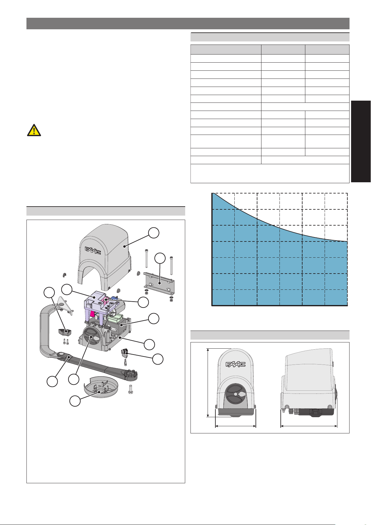
1
2
350 Kg
2. TECHNICAL SPECIFICATIONS
LEDOM E193 193
ylppusrewoP~V032-
rotomcirtcelEcdV42cdV42
rewopdebrosbAW021W011
euqrotxaMm/N052m/N052
deepsralugnaxaMces/°31ces/°31
2-1
faelxaM
2
thgiewfaelxaM
C°02taycneuqerfesUyad/selcyc08yad/selcyc08
C°02taselcycevitucesnoC0303
ssalCnoitcetorP44PI44PI
gnitarepO
snoisnemiD2.gifeeS
.faeleht
thgiewehT P htgnelehtfonoitcnufasifaelehtfo L enozehtnisifaelruoyfikcehC.
tneibma
erutarepmet
thgiewrotarepOgK7.8gK7
.htaenrednuhpargehtninwohs
m5.2m5.2
hpargeeS
C°55+C°02-C°55+C°02-
gnikcoleetnaraugotdellatsniebtsumkcolcirtcelena,m2>LhtgnelahtiwsevaelroF
ENGLISH
1. COMPONENTS
300 Kg
250 Kg
8
200 Kg
9
150 Kg
100 Kg
3
6
5
2
50 Kg
0Kg
1m
1.5 m
1.8 m
2.3 m
2.5 m
2m
3. DIMENSIONS
1
6
7
4
312 mm
1rotomraeG
2remrofsnarT
3)ylnorotomretsamrof(tinulortnoC
4ecivedesaeleR
5)lanoitpo(eludomrevieceR
6spotslacinahc
eM
7mranoissimsnarT
8gnisuohgnirevoC
9tekcarbraeR
01gnisuohrewoL
10
FIG. 1
185 mm
7
260 mm
F
IG. 2
Page 4

1
1
1
4. ELECTRICAL CONNECTIONS
• The lay-out below refers to an installation with two
motors, with all safety and signalling devices
connected.
1E193rotomraeG
2*193rotomraeG
3pmalgnihsalF
ENGLISH
4hctiwsrotcelesdetarepo-yeK
5rettimsnartllecotohP
6reviecerllecotohP
7**kcolcirtcelE
)m2>Lfaelrofyrotagilbo(**
5. INSTALLATION
5.1. PRELIMINARY CHECKS
To ensure a correctly operating automated system, the structure
of the gate to be moved must satisfy the following requirements:
• The mechanical construction elements must comply with the
provisions of the EN12604 and EN 12605 standards.
• leaf length must conform to the operator characteristics (see
paragraph 2)
• sturdy, rigid gate structure, suitable for the automated system
• smooth, uniform gate movement, without any friction and
jamming during the entire opening;
• adequately sturdy hinges, in good condition
• an efficient earth socket for connection of the operator
• If the thrust values are not within the values specified
in UNI EN12453 standard, the zone indicated in figure
4 MUST be protected with a protective device
conforming to the UNI EN12978 standard.
B
125
20
30
40
50
60
70
80
90
100
110
120
A
130
140
150
)snoitacilppafaelowtrofylno(*
IG. 3
F
160
170
180
190
200
210
220
90°-95°
• The operator was studied and made to be secured
vertically (Fig.5). The operator cannot be installed in
other positions.
135
145
155
165
95°-100°
175
185
a
195
205
100°-105°
215
225
B
235
110°
105°-
a
450 Min.
A
245
255
110°-115
X
265
275
115°-120°
°
FIG. 4
We advise you to carry out the metalwork jobs if any,
before installing the automated system.
The condition of the gate structure directly influences
the reliability and safety of the automated system.
5.2 INSTALLATION DIMENSIONS
Procedure for finding the securing position of the operator, using
Fig.4 to help you:
• measure dimension “A” of the gate and trace a horizontal
line on the graph on the measured value, this line to cross the
whole graph.
• you will obtain the maximum permissible angular opening
according to dimension “A” of the graph.
• select the opening range you require
• select dimension “B” so that it intersects the horizontal line
(dimension “A”) inside the required opening range.
• If dimension “A” permits opening values greater than
the opening value selected, the value of dimension
“B” can change up to the maximum permissible
opening value.
• Make sure that the minimum dimension of 450mm in
Fig.4 is observed.
• When the operator has been installed, check if
dimension “X” in Fig.4 is minimum 500 mm. If dimension
“X” is less than 500mm, run an impact test on the point
indicated in Fig.4, as described in UNI EN12445
standard, and make sure that the measured values
conform to the specifications of UNI EN 12453 standard.
X
X
F
IG. 5
5.3. INSTALLING THE OPERATOR
When you have established dimensions “A” and “B”, you can
install the operator as follows:
Loosen by about 1/2 turn the four securing screws of the
upper housing (Fig.6 ref.) and withdraw the housing. Set
the operator for manual operation, see paragraph 7.
IG. 6
8
F
Page 5

1
2
F
N
2A 450V 5x20
Establish the height of the
operator, bearing in mind that:
• the securing bracket of the
curved arm must be in a zone
where it can be secured to the
gate leaf (Fig.7)
• the minimum off ground height
of the operator must permit
securing the curved arm and
positioning the lower housing
(at least 85mm, see fig.7).
> 85mm
• the lower edge of the rear
bracket must be aligned with
respect to the upper edge of
the front bracket (Fig.8).
Secure the rear bracket in the
position you had established,
using four M8 screws. As you secure
the bracket, respect the lay-out
in Fig. 9 and check, using a level,
if the bracket is horizontal.
• To improve water tightness, the external housing covers
the securing bracket - this prevents the bracket from
being directly welded on the pilaster.
• The rear bracket must be secured on an as smooth as
possible surface. For masonry pilasters, a
counter-plate for walling is available as an accessory.
Position the operator on the
bracket you have just secured,
using two M8x100 screws and
the relevant nuts - supplied
(Fig.10).
Set the operator for manual
operation, see paragraph 7.
F
IG. 10
X
F
F
F
IG. 7
IG. 8
IG. 9
Secure the bracket in the established position using two M8
screws.
1
3
2
20 mm
IG. 13
F
We advise you to secure the bracket with the screws,
and not weld it to the leaf, in order not to rule out
future adjustments.
Move the bracket by hand and - with the leaf in closing
position - make sure that the two arms do not impact each
other, as shown in Fig. 13 ref. .
Take the operator back to the work position - see paragraph 7.
5.4. WIRING THE OPERATOR
When you have finished securing the operator, you can wire it.
There are three holes in the lower part of the operator. They
should be used for positioning the cable grippers, for routing the
power cables, for connecting accessories and, if necessary, for
connecting the second motor.
Install all the three supplied cable grippers with the securing
nuts (Fig. 14).
• Always use the largest cable gripper (Fig.14 ref.)
• If the other two cable grippers are not used, they must
be closed, using the supplied plugs (Fig.14 ref.). Fit
the plastic plug in the cable routing hole and close
the cable gripper until it is tight.
ENGLISH
Install the straight arm (Fig.11) with the
supplied screw.
FIG. 11
Assemble the rest of the arm as illustrated in Fig.12.
For correct operation, tighten the two securing screws
(Fig.12 ref.) and then loosen them by about 1/2 turn
to enable rotation without any friction on the arms.
1
1
F
IG. 12
Align the arms you have just assembled, pushing in the central
zone until they stop, see Fig. 13 ref. .
There are two stops on the curved arm to facilitate the
aligning operation.
Rest the front bracket on the leaf, Fig.13 ref. .
Move back the front bracket by about 20 mm and mark the
securing holes, Fig. 13 ref. .
Connect the power cable, as shown in Fig.15. The earthing
wire must also be connected. Make sure that the power
cable wires are correctly fitted in the 'comb' which restrains
them Fig. 15.
IG. 14
F
F
IG. 15
• If the protective fuse has to be replaced, use a fuse
with the following characteristics:
5x20 2A 450V
Wire all the accessories and safety devices, observing the
relevant instructions.
9
Page 6

1
2
3
5.5. POSITIONING THE MECHANICAL STOPS
The 391 operator is supplied standard with opening and closing
mechanical stops. This is to facilitate the installation operations
because there is no need to construct the mechanical stop
elements. The mechanical stops should be fitted in the lower
part of the operator, coupled to a toothed sector. Installation
procedure for the stops:
OPENING MECHANICAL STOP
Set the operator for manual
operation, see paragraph 7.
Manually move the leaf to its
opening position.
Take the mechanical stop as close
as possible to the straight arm and
fasten the two securing screws.
• Make sure that the toothed sector is coupled
correctly.
CLOSING MECHANICAL STOP
ENGLISH
• Use the closing mechanical stop only in the absence
of a mechanical stop on the closing leaf.
• The closing mechanical stop does not guarantee
locking the leaf in case of burglary.
Set the operator for manual operation, see paragraph 7.
Manually move the leaf to its closed position.
Take the mechanical stop as close as possible to the straight
arm and fasten the two securing screws.
• Make sure that the toothed sector is coupled
correctly.
6. AUTOMATED SYSTEM TEST
FIG. 16
7. MANUAL MODE OPERATION
If the operator has to be manually activated due to a power
cut or to an operator fault, proceed as follows:
Cut power to the system with the differential switch.
Lift the protective plug from the lock, fig.18 ref.
Fit the key and turn it anti-clockwise until it stops, fig.18 ref. .
Turn the release knob clockwise until it stops, fig.18 ref. .
Move the leaf by hand.
IG. 18
F
Procedure for restoring normal operation:
Make sure that the system is not powered.
Position the leaf to its closing position.
Turn the release knob anti-clockwise until it stops, then turn
the key clockwise until it stops and remove it.
Check if the release device has been correctly engaged, by
trying to move the leaf by hand. The leaf must be locked
and it must not be possible to move it by hand.
Re-position the lock covering plug.
Restore power to the system and command an opening
cycle.
• The operator may not correctly execute the
decelerations on the first cycle. Wait for the end of the
cycle and give another opening command.
• When you have made all the necessary electrical
connections, power up the system and program the control
unit according to your requirements.
• Run the test for the automation and for all the connected
accessories, taking great care when checking the safety
devices.
• Re-locate the upper covering housing, tighten the securing
screws and position the four covering plugs fig.17 ref. .
• Position the lower housing as shown in fig.17 ref. .
• Hand the "User's Guide" booklet to the customer and describe
its correct operation and use.
• Point out, to the end user, any residual risks present in
the installation.
1
1
1
8. SPECIAL APPLICATIONS
Applications other than those in this manual are EXPRESSLY
PROHIBITED
9. MAINTENANCE
To ensure correct long-term operation and a constant level of
safety, we advise you to generally control the system every 6
months. In the “User ’s Guide” booklet, there is a form for recording
jobs.
10. REPAIRS
The User must not in any way attempt to repair or to take direct
action and must solely contact qualified FAAC personnel or
FAAC service centres.
11. ACCESSORIES
For accessories, see the FAAC catalogue.
2
IG. 17
F
10
Page 7

7) No instalen el aparato en atmósfera explosiva: la presencia de gas o humos
inflamables constituye un grave peligro para la seguridad.
8) Los elementos constructivos mecánicos deben estar de acuerdo con lo establecido
en las Normas EN 12604 y EN 12605.
Para los países no pertenecientes a la CEE, además de las referencias normativas
nacionales, para obtener un nivel de seguridad adecuado, deben seguirse las
Normas arriba indicadas.
9) FAAC no es responsable del incumplimiento de las buenas técnicas de fabricación de los cierres que se han de motorizar, así como de las deformaciones que
pudieran intervenir en la utilización.
10) La instalación debe ser realizada de conformidad con las Normas EN 12453 y EN
12445. El nivel de seguridad de la automación debe ser C+D.
11) Quiten la alimentación eléctrica y desconecten las baterías antes de efectuar
cualquier intervención en la instalación.
12) Coloquen en la red de alimentación de la automación un interruptor omnipolar
con distancia de apertura de los contactos igual o superior a 3 mm. Se aconseja
usar un magnetotérmico de 6A con interrupción omnipolar.
13) Comprueben que la instalación disponga línea arriba de un interruptor diferencial
con umbral de 0,03 A.
14) Verifiquen que la instalación de tierra esté correctamente realizada y conecten
las partes metálicas del cierre.
15) La automación dispone de un dispositivo de seguridad antiaplastamiento constituido por un control de par. No obstante, es necesario comprobar el umbral de
intervención según lo previsto en las Normas indicadas en el punto 10.
16) Los dispositivos de seguridad (norma EN 12978) permiten proteger posibles áreas
de peligro de Riesgos mecánicos de movimiento, como por ej. aplastamiento,
arrastre, corte.
17) Para cada equipo se aconseja usar por lo menos una señalización luminosa
así como un cartel de señalización adecuadamente fijado a la estructura del
bastidor, además de los dispositivos indicados en el “16”.
18) FAAC declina toda responsabilidad relativa a la seguridad y al buen funcionamiento de la automación si se utilizan componentes de la instalación que no
sean de producción FAAC.
19) Para el mantenimiento utilicen exclusivamente piezas originales FAAC
20) No efectúen ninguna modificación en los componentes que forman parte del
sistema de automación.
21) El instalador debe proporcionar todas las informaciones relativas al funcionamiento del sistema en caso de emergencia y entregar al usuario del equipo el
manual de advertencias que se adjunta al producto.
22) No permitan que niños o personas se detengan en proximidad del producto
durante su funcionamiento.
23) Mantengan lejos del alcance los niños los telemandos o cualquier otro emisor
de impulso, para evitar que la automación pueda ser accionada involuntariamente.
24) Sólo puede transitarse entre las hojas si la cancela está completamente abierta.
25) El usuario debe abstenerse de intentar reparar o de intervenir directamente,
y debe dirigirse exclusivamente a personal cualificado FAAC o a centros de
asistencia FAAC.
26) Todo lo que no esté previsto expresamente en las presentes instrucciones debe
entenderse como no permitido
HINWEISE FÜR DEN INSTALLATIONSTECHNIKER
1) ACHTUNG! Um die Sicherheit von Personen zu gewährleisten, sollte die Anleitung
aufmerksam befolgt werden. Eine falsche Installation oder ein fehlerhafter Betrieb
des Produktes können zu schwerwiegenden Personenschäden führen.
2) Bevor mit der Installation des Produktes begonnen wird, sollten die Anleitungen
aufmerksam gelesen werden.
3) Das Verpackungsmaterial (Kunststoff, Styropor, usw.) sollte nicht in Reichweite von
Kindern aufbewahrt werden, da es eine potentielle Gefahrenquelle darstellt.
4) Die Anleitung sollte aufbewahrt werden, um auch in Zukunft Bezug auf sie nehmen
zu können.
5) Dieses Produkt wurde ausschließlich für den in diesen Unterlagen angegebenen Gebrauch entwickelt und hergestellt. Jeder andere Gebrauch, der nicht ausdrücklich
angegeben ist, könnte die Unversehrtheit des Produktes beeinträchtigen und/oder
eine Gefahrenquelle darstellen.
6) Die Firma FAAC lehnt jede Haftung für Schäden, die durch unsachgemäßen oder
nicht bestimmungsgemäßen Gebrauch der Automatik verursacht werden, ab.
7) Das Gerät sollte nicht in explosionsgefährdeten Umgebungen installiert werden:
das Vorhandensein von entflammbaren Gasen oder Rauch stellt ein schwerwiegendes Sicherheitsrisiko dar.
8) Die mechanischen Bauelemente müssen den Anforderungen der Normen EN
12604 und EN 12605 entsprechen.
Für Länder, die nicht der Europäischen Union angehören, sind für die Gewährleistung eines entsprechenden Sicherheitsniveaus neben den nationalen gesetzlichen
Bezugsvorschriften die oben aufgeführten Normen zu beachten.
9) Die Firma FAAC übernimmt keine Haftung im Falle von nicht fachgerechten Ausführungen bei der Herstellung der anzutreibenden Schließvorrichtungen sowie
bei Deformationen, die eventuell beim Betrieb entstehen.
10) Die Installation muß unter Beachtung der Normen EN 12453 und EN 12445 erfolgen.
Die Sicherheitsstufe der Automatik sollte C+D sein.
11) Vor der Ausführung jeglicher Eingriffe auf der Anlage sind die elektrische Versorgung und die Batterie abzunehmen.
12) Auf dem Versorgungsnetz der Automatik ist ein omnipolarer Schalter mit Öffnungsabstand der Kontakte von über oder gleich 3 mm einzubauen. Darüber hinaus
wird der Einsatz eines Magnetschutzschalters mit 6A mit omnipolarer Abschaltung
empfohlen.
13) Es sollte überprüft werden, ob vor der Anlage ein Differentialschalter mit einer
Auslöseschwelle von 0,03 A zwischengeschaltet ist.
14) Es sollte überprüft werden, ob die Erdungsanlage fachgerecht ausgeführt wurde.
Die Metallteile der Schließung sollten an diese Anlage angeschlossen werden.
15) Die Automation verfügt über eine eingebaute Sicherheitsvorrichtung für den
Quetschschutz, die aus einer Drehmomentkontrolle besteht. Es ist in jedem Falle
erforderlich, deren Eingriffsschwelle gemäß der Vorgaben der unter Punkt 10
angegebenen Vorschriften zu überprüfen.
16) Die Sicherheitsvorrichtungen (Norm EN 12978) ermöglichen den Schutz eventueller Gefahrenbereiche vor mechanischen Bewegungsrisiken, wie zum Beispiel
Quetschungen, Mitschleifen oder Schnittverletzungen.
17) Für jede Anlage wird der Einsatz von mindestens einem Leuchtsignal empfohlen
ALLGEMEINE SICHERHEITSVORSCHRIFTEN
sowie eines Hinweisschildes, das über eine entsprechende Befestigung mit dem
Aufbau des Tors verbunden wird. Darüber hinaus sind die unter Punkt “16” erwähnten Vorrichtungen einzusetzen.
18) Die Firma FAAC lehnt jede Haftung hinsichtlich der Sicherheit und des störungsfreien Betriebs der Automatik ab, soweit Komponenten auf der Anlage eingesetzt
werden, die nicht im Hause FAAC hergestellt urden.
19) Bei der Instandhaltung sollten ausschließlich Originalteile der Firma FAAC verwendet werden.
20) Auf den Komponenten, die Teil des Automationssystems sind, sollten keine Veränderungen vorgenommen werden.
21) Der Installateur sollte alle Informationen hinsichtlich des manuellen Betriebs des
Systems in Notfällen liefern und dem Betreiber der Anlage das Anleitungsbuch,
das dem Produkt beigelegt ist, übergeben.
22) Weder Kinder noch Erwachsene sollten sich während des Betriebs in der unmittelbaren Nähe der Automation aufhalten.
23) Die Funksteuerungen und alle anderen Impulsgeber sollten außerhalb der Reichweite von Kindern aufbewahrt werden, um ein versehentliches Aktivieren der
Automation zu vermeiden.
24) Der Durchgang oder die Durchfahrt zwischen den Flügeln darf lediglich bei
vollständig geöffnetem Tor erfolgen.
25) Der Benutzer darf direkt keine Versuche für Reparaturen oder Arbeiten vornehmen
und hat sich ausschließlich an qualifiziertes Fachpersonal FAAC oder an Kundendienstzentren FAAC zu wenden.
26) Alle Vorgehensweisen, die nicht ausdrücklich in der vorliegenden Anleitung
vorgesehen sind, sind nicht zulässig
WAARSCHUWINGEN VOOR DE INSTALLATEUR
1) LET OP! Het is belangrijk voor de veiligheid dat deze hele instructie zorgvuldig wordt
opgevolgd. Een onjuiste installatie of foutief gebruik van het product kunnen ernstig
persoonlijk letsel veroorzaken.
2) Lees de instructies aandachtig door alvorens te beginnen met de installatie van
het product.
3) De verpakkingsmaterialen (plastic, polystyreen, enz.) mogen niet binnen het bereik
van kinderen worden gelaten, want zij vormen een mogelijke bron van gevaar.
4) Bewaar de instructies voor raadpleging in de toekomst.
5) Dit product is uitsluitend ontworpen en gebouwd voor het doel dat in deze documentatie wordt aangegeven. Elk ander gebruik, dat niet uitdrukkelijk wordt
vermeld, zou het product kunnen beschadigen en/of een bron van gevaar
kunnen vormen.
6) FAAC aanvaardt geen enkele aansprakelijkheid voor schade die ontstaat uit
oneigenlijk gebruik of ander gebruik dan waarvoor het automatische systeem
is bedoeld.
7) Installeer het apparaat niet in een explosiegevaarlijke omgeving: de aanwezigheid van ontvlambare gassen of dampen vormt een ernstig gevaar voor de
veiligheid.
8) De mechanische bouwelementen moeten in overeenstemming zijn met de bepalingen van de normen EN 12604 en EN 12605.
Voor niet-EEG landen moeten, om een goed veiligheidsniveau te bereiken,
behalve de nationale voorschriften ook de bovenstaande normen in acht worden genomen.
9) FAAC is niet aansprakelijk als de regels der goede techniek niet in acht genomen
zijn bij de bouw van het sluitwerk dat gemotoriseerd moet worden, noch voor
vervormingen die zouden kunnen ontstaan bij het gebruik.
10) De installatie dient te geschieden in overeenstemming met de normen EN 12453 en
EN 12445. Het veiligheidsniveau van het automatische systeem moet C+D zijn.
11) Alvorens ingrepen te gaan verrichten op de installatie moet de elektrische voeding
worden weggenomen en moeten de batterijen worden afgekoppeld.
12) Zorg op het voedingsnet van het automatische systeem voor een meerpolige
schakelaar met een opening tussen de contacten van 3 mm of meer. Het wordt
geadviseerd een magnetothermische schakelaar van 6A te gebruiken met
meerpolige onderbreking.
13) Controleer of er bovenstrooms van de installatie een differentieelschakelaar is
geplaatst met een limiet van 0,03 A.
14) Controleer of de aardingsinstallatie vakkundig is aangelegd en sluit er de metalen
delen van het sluitsysteem op aan.
15) Het automatische systeem beschikt over een intrinsieke beveiliging tegen inklemming, bestaande uit een controle van het koppel. De inschakellimiet hiervan
dient echter te worden gecontroleerd volgens de bepalingen van de normen die
worden vermeld onder punt 10.
16) De veiligheidsvoorzieningen (norm EN 12978) maken het mogelijk eventuele gevaarlijke gebieden te beschermen tegen Mechanische gevaren door beweging,
zoals bijvoorbeeld inklemming, meesleuren of amputatie.
17) Het wordt voor elke installatie geadviseerd minstens één lichtsignaal te gebruiken
alsook een waarschuwingsbord dat goed op de constructie van het hang- en
sluitwerk dient te worden bevestigd, afgezien nog van de voorzieningen die
genoemd zijn onder punt “16”.
18) FAAC aanvaardt geen enkele aansprakelijkheid voor wat betreft de veiligheid en
de goede werking van het automatische systeem, als er in de installatie gebruik
gemaakt wordt van componenten die niet door FAAC zijn geproduceerd.
19) Gebruik voor het onderhoud uitsluitend originele FAAC-onderdelen.
20) Verricht geen wijzigingen op componenten die deel uitmaken van het automatische systeem.
21) De installateur dient alle informatie te verstrekken over de handbediening van
het systeem in noodgevallen, en moet de gebruiker van de installatie het bij het
product geleverde boekje met aanwijzingen overhandigen.
22) Sta het niet toe dat kinderen of volwassenen zich ophouden in de buurt van het
product terwijl dit in werking is.
23) Houd radio-afstandsbedieningen of alle andere impulsgevers buiten het bereik
van kinderen, om te voorkomen dat het automatische systeem onopzettelijk kan
worden aangedreven.
24) Ga alleen tussen de vleugels door als het hek helemaal geopend is.
25) De gebruiker mag zelf geen pogingen ondernemen tot reparaties of andere
directe ingrepen, en dient zich uitsluitend te wenden tot gekwalificeerd en geautoriseerd FAAC-personeel of een erkend FAAC-servicecentrum.
26) Alles wat niet uitdrukkelijk in deze instructies wordt aangegeven, is niet toege-
ALGEMENE VEILIGHEIDSVOORSCHRIFTEN
Page 8

AVVERTENZE PER L’INSTALLATORE
1) ATTENZIONE! È importante per la sicurezza delle persone seguire attentamente
tutta l’istruzione. Una errata installazione o un errato uso del prodotto può portare
a gravi danni alle persone.
2) Leggere attentamente le istruzioni prima di iniziare l’installazione del prodotto.
3) I materiali dell’imballaggio (plastica, polistirolo, ecc.) non devono essere lasciati
alla portata dei bambini in quanto potenziali fonti di pericolo.
4) Conservare le istruzioni per riferimenti futuri.
5) Questo prodotto è stato progettato e costruito esclusivamente per l’utilizzo indicato
in questa documentazione. Qualsiasi altro utilizzo non espressamente indicato potrebbe pregiudicare l’integrità del prodotto e/o rappresentare fonte di pericolo.
6) FAAC declina qualsiasi responsabilità derivata dall’uso improprio o diverso da
quello per cui l’automatismo è destinato.
7) Non installare l’apparecchio in atmosfera esplosiva: la presenza di gas o fumi
infiammabili costituisce un grave pericolo per la sicurezza.
8) Gli elementi costruttivi meccanici devono essere in accordo con quanto stabilito
dalle Norme EN 12604 e EN 12605.
Per i Paesi extra-CEE, oltre ai riferimenti normativi nazionali, per ottenere un livello
di sicurezza adeguato, devono essere seguite le Norme sopra riportate.
9) FAAC non è responsabile dell’inosservanza della Buona Tecnica nella costruzione
delle chiusure da motorizzare, nonché delle deformazioni che dovessero intervenire nell’utilizzo.
10) L’installazione deve essere effettuata nell’osservanza delle Norme EN 12453 e EN
12445. Il livello di sicurezza dell’automazione deve essere C+D.
11) Prima di effettuare qualsiasi intervento sull’impianto, togliere l’alimentazione
elettrica e scollegare le batterie.
12) Prevedere sulla rete di alimentazione dell’automazione un interruttore onnipolare
con distanza d’apertura dei contatti uguale o superiore a 3 mm. È consigliabile
l’uso di un magnetotermico da 6A con interruzione onnipolare.
13) Verificare che a monte dell’impianto vi sia un interruttore differenziale con soglia
da 0,03 A.
14) Verificare che l’impianto di terra sia realizzato a regola d’arte e collegarvi le parti
metalliche della chiusura.
15) L’automazione dispone di una sicurezza intrinseca antischiacciamento costituita
da un controllo di coppia. E’ comunque necessario verificarne la sogli di intervento
secondo quanto previsto dalle Norme indicate al punto 10.
16) I dispositivi di sicurezza (norma EN 12978) permettono di proteggere eventuali
aree di pericolo da Rischi meccanici di movimento, come ad Es. schiacciamento,
convogliamento, cesoiamento.
17) Per ogni impianto è consigliato l’utilizzo di almeno una segnalazione luminosa
nonché di un cartello di segnalazione fissato adeguatamente sulla struttura dell’infisso, oltre ai dispositivi citati al punto “16”.
18) FAAC declina ogni responsabilità ai fini della sicurezza e del buon funzionamento
dell’automazione, in caso vengano utilizzati componenti dell’impianto non di
produzione FAAC.
19) Per la manutenzione utilizzare esclusivamente parti originali FAAC.
20) Non eseguire alcuna modifica sui componenti facenti parte del sistema d’automazione.
21) L’installatore deve fornire tutte le informazioni relative al funzionamento manuale
del sistema in caso di emergenza e consegnare all’Utente utilizzatore dell’impianto
il libretto d’avvertenze allegato al prodotto.
22) Non permettere ai bambini o persone di sostare nelle vicinanze del prodotto
durante il funzionamento.
23) Tenere fuori dalla portata dei bambini radiocomandi o qualsiasi altro datore di impulso, per evitare che l’automazione possa essere azionata involontariamente.
24) Il transito tra le ante deve avvenire solo a cancello completamente aperto.
25) L’utente utilizzatore deve astenersi da qualsiasi tentativo di riparazione o d’intervento e deve rivolgersi solo ed esclusivamente a personale qualificato FAAC o
centri d’assistenza FAAC.
26) Tutto quello che non è previsto espressamente in queste istruzioni non è permesso
1) ATTENTION! To ensure the safety of people, it is important that you read all the
following instructions. Incorrect installation or incorrect use of the product could
cause serious harm to people.
2) Carefully read the instructions before beginning to install the product.
3) Do not leave packing materials (plastic, polystyrene, etc.) within reach of children
as such materials are potential sources of danger.
4) Store these instructions for future reference.
5) This product was designed and built strictly for the use indicated in this documentation. Any other use, not expressly indicated here, could compromise the good
condition/operation of the product and/or be a source of danger.
6) FAAC declines all liability caused by improper use or use other than that for which
the automated system was intended.
7) Do not install the equipment in an explosive atmosphere: the presence of inflammable gas or fumes is a serious danger to safety.
8) The mechanical parts must conform to the provisions of Standards EN 12604 and
EN 12605.
For non-EU countries, to obtain an adequate level of safety, the Standards mentioned above must be observed, in addition to national legal regulations.
9) FAAC is not responsible for failure to observe Good Technique in the construction
of the closing elements to be motorised, or for any deformation that may occur
during use.
10) The installation must conform to Standards EN 12453 and EN 12445. The safety
level of the automated system must be C+D.
11) Before attempting any job on the system, cut out electrical power and disconnect the batteries.
12) The mains power supply of the automated system must be fitted with an all-pole
switch with contact opening distance of 3mm or greater. Use of a 6A thermal
breaker with all-pole circuit break is recommended.
13) Make sure that a differential switch with threshold of 0.03 A is fitted upstream of
the system.
14) Make sure that the earthing system is perfectly constructed, and connect metal
parts of the means of the closure to it.
15) The automated system is supplied with an intrinsic anti-crushing safety device
consisting of a torque control. Nevertheless, its tripping threshold must be checked
OBBLIGHI GENERALI PER LA SICUREZZA
IMPORTANT NOTICE FOR THE INSTALLER
GENERAL SAFETY REGULATIONS
as specified in the Standards indicated at point 10.
16) The safety devices (EN 12978 standard) protect any danger areas against mecha-
nical movement Risks, such as crushing, dragging, and shearing.
17) Use of at least one indicator-light is recommended for every system, as well as a
warning sign adequately secured to the frame structure, in addition to the devices
mentioned at point “16”.
18) FAAC declines all liability as concerns safety and efficient operation of the automated system, if system components not produced by FAAC are used.
19) For maintenance, strictly use original parts by FAAC.
20) Do not in any way modify the components of the automated system.
21) The installer shall supply all information concerning manual operation of the system
in case of an emergency, and shall hand over to the user the warnings handbook
supplied with the product.
22) Do not allow children or adults to stay near the product while it is operating.
23) Keep remote controls or other pulse generators away from children, to prevent
the automated system from being activated involuntarily.
24) Transit through the leaves is allowed only when the gate is fully open.
25) The User must not in any way attempt to repair or to take direct action and must
solely contact qualified FAAC personnel or FAAC service centres.
26) Anything not expressly specified in these instructions is not permitted.
CONSIGNES POUR L’INSTALLATEUR
1) ATTENTION! Il est important, pour la sécurité des personnes, de suivre à la lettre
toutes les instructions. Une installation erronée ou un usage erroné du produit peut
entraîner de graves conséquences pour les personnes.
2) Lire attentivement les instructions avant d’installer le produit.
3) Les matériaux d’emballage (matière plastique, polystyrène, etc.) ne doivent pas
être laissés à la portée des enfants car ils constituent des sources potentielles de
danger.
4) Conserver les instructions pour les références futures.
5) Ce produit a été conçu et construit exclusivement pour l’usage indiqué dans
cette documentation. Toute autre utilisation non expressément indiquée pourrait
compromettre l’intégrité du produit et/ou représenter une source de danger.
6) FAAC décline toute responsabilité qui dériverait d’usage impropre ou différent de
celui auquel l’automatisme est destiné.
7) Ne pas installer l’appareil dans une atmosphère explosive: la présence de gaz ou
de fumées inflammables constitue un grave danger pour la sécurité.
8) Les composants mécaniques doivent répondre aux prescriptions des Normes EN
12604 et EN 12605.
Pour les Pays extra-CEE, l’obtention d’un niveau de sécurité approprié exige non
seulement le respect des normes nationales, mais également le respect des
Normes susmentionnées.
9) FAAC n’est pas responsable du non-respect de la Bonne Technique dans la construction des fermetures à motoriser, ni des déformations qui pourraient intervenir
lors de l’utilisation.
10) L’installation doit être effectuée conformément aux Normes EN 12453 et EN 12445.
Le niveau de sécurité de l’automatisme doit être C+D.
11) Couper l’alimentation électrique et déconnecter la batterie avant toute intervention sur l’installation.
12) Prévoir, sur le secteur d’alimentation de l’automatisme, un interrupteur omnipolaire avec une distance d’ouverture des contacts égale ou supérieure à 3
mm. On recommande d’utiliser un magnétothermique de 6A avec interruption
omnipolaire.
13) Vérifier qu’il y ait, en amont de l’installation, un interrupteur différentiel avec un
seuil de 0,03 A.
14) Vérifier que la mise à terre est réalisée selon les règles de l’art et y connecter les
pièces métalliques de la fermeture.
15) L’automatisme dispose d’une sécurité intrinsèque anti-écrasement, formée d’un
contrôle du couple. Il est toutefois nécessaire d’en vérifier le seuil d’intervention
suivant les prescriptions des Normes indiquées au point 10.
16) Les dispositifs de sécurité (norme EN 12978) permettent de protéger des zones
éventuellement dangereuses contre les Risques mécaniques du mouvement,
comme l’écrasement, l’acheminement, le cisaillement.
17) On recommande que toute installation soit doté au moins d’une signalisation
lumineuse, d’un panneau de signalisation fixé, de manière appropriée, sur la
structure de la fermeture, ainsi que des dispositifs cités au point “16”.
18) FAAC décline toute responsabilité quant à la sécurité et au bon fonctionnement
de l’automatisme si les composants utilisés dans l’installation n’appartiennent pas
à la production FAAC.
19) Utiliser exclusivement, pour l’entretien, des pièces FAAC originales.
20) Ne jamais modifier les composants faisant partie du système d’automatisme.
21) L’installateur doit fournir toutes les informations relatives au fonctionnement manuel du système en cas d’urgence et remettre à l’Usager qui utilise l’installation
les “Instructions pour l’Usager” fournies avec le produit.
22) Interdire aux enfants ou aux tiers de stationner près du produit durant le fonctionnement.
23) Eloigner de la portée des enfants les radiocommandes ou tout autre générateur
d’impulsions, pour éviter tout actionnement involontaire de l’automatisme.
24) Le transit entre les vantaux ne doit avoir lieu que lorsque le portail est complètement ouvert.
25) L’utilisateur doit s’abstenir de toute tentative de réparation ou d’intervention et
doit s’adresser uniquement et exclusivement au personnel qualifié FAAC ou aux
centres d’assistance FAAC.
26) Tout ce qui n’est pas prévu expressément dans ces instructions est interdit.
RÈGLES DE SÉCURITÉ
ADVERTENCIAS PARA EL INSTALADOR
1) ATENCION! Es sumamente importante para la seguridad de las personas seguir
atentamente las presentes instrucciones. Una instalación incorrecta o un uso
impropio del producto puede causar graves daños a las personas.
2) Lean detenidamente las instrucciones antes de instalar el producto.
3) Los materiales del embalaje (plástico, poliestireno, etc.) no deben dejarse al alcance de los niños, ya que constituyen fuentes potenciales de peligro.
4) Guarden las instrucciones para futuras consultas.
5) Este producto ha sido proyectado y fabricado exclusivamente para la utilización
indicada en el presente manual. Cualquier uso diverso del previsto podría perjudicar el funcionamiento del producto y/o representar fuente de peligro.
6) FAAC declina cualquier responsabilidad derivada de un uso impropio o diverso
del previsto.
REGLAS GENERALES PARA LA SEGURIDAD
Page 9

Le descrizioni e le illustrazioni del presente manuale non sono impegnative. La FAAC si riserva il diritto, lasciando inalterate le caratteristiche essenziali dell’apparecchiatura, di apportare in qualunque momento e senza impegnarsi
ad aggiornare la presente pubblicazione, le modifiche che essa ritiene convenienti per miglioramenti tecnici o per
qualsiasi altra esigenza di carattere costruttivo o commerciale.
The descriptions and illustrations contained in the present manual are not binding. FAAC reserves the right, whilst
leaving the main features of the equipments unaltered, to undertake any modifications it holds necessary for either
technical or commercial reasons, at any time and without revising the present publication.
Les descriptions et les illustrations du présent manuel sont fournies à titre indicatif. FAAC se réserve le droit d’apporter à
tout moment les modifications qu’elle jugera utiles sur ce produit tout en conservant les caractéristiques essentielles,
sans devoir pour autant mettre à jour cette publication.
Die Beschreibungen und Abbildungen in vorliegendem Handbuch sind unverbindlich. FAAC behält sich das Recht
vor, ohne die wesentlichen Eigenschaften dieses Gerätes zu verändern und ohne Verbindlichkeiten in Bezug auf die
Neufassung der vorliegenden Anleitungen, technisch bzw. konstruktiv/kommerziell bedingte Verbesserungen vorzunehmen.
Las descripciones y las ilustraciones de este manual no comportan compromiso alguno. FAAC se reserva el derecho,
dejando inmutadas las características esenciales de los aparatos, de aportar, en cualquier momento y sin comprometerse a poner al día la presente publicación, todas las modificaciones que considere oportunas para el perfeccionamiento técnico o para cualquier otro tipo de exigencia de carácter constructivo o comercial.
De beschrijvingen in deze handleiding zijn niet bindend. FAAC behoudt zich het recht voor op elk willekeurig moment de
veranderingen aan te brengen die het bedrijf nuttig acht met het oog op technische verbeteringen of alle mogelijke
andere productie- of commerciële eisen, waarbij de fundamentele eigenschappen van de apparaat gehandhaafd
blijven, zonder zich daardoor te verplichten deze publicatie bij te werken.
FAAC S.p.A.
Via Benini, 1
40069 Zola Predosa (BO) - ITALIA
Tel. 0039.051.61724 - Fax. 0039.051.758518
www.faac.it
www.faacgroup.com
I0594 Rev.2
 Loading...