

Page 1

Installation Manual
390
Swing Gate System
Leading the way ...
Leading the way ...
Page 2
CE DECLARATION OF MACHINE CONFORMITY
(DIRECTIVE 89/392/EEC, ANNEX II, PART B)
Manufacturer : FAAC S.p.A.
Address: Via Benini, 1 - 40069 Zola Predosa BOLOGNA - ITALY
Declares that: Operator mod. 390
• is manufactured to be incorporated in a machine or for assembly with other machines to constitute a machine
under the provisions of Directive 89/392/EEC, and subsequent amendments 91/368/EEC, 93/44/EEC, 93/68/
EEC;
• conforms to the essential safety requirements of the following further EEC Directives:
73/23/EEC and subsequent amendment 93/68/EEC.
89/336/EEC and subsequent amendment 92/31/EEC and 93/68/EEC
and, furthermore, declares that
putting the machine into service is forbidden until the machine in which it
will be incorporated or of which it will become a part has been identified and it has been declared as
conforming to the conditions of Directive 89/392/EEC and subsequent amendments enacted by the national
implementing legislation.
Bologna, 01 January 2003
The Managing Director
A. Bassi
WARNINGS FOR THE INSTALLER
GENERAL SAFETY OBLIGATIONS
1) ATTENTION! To ensure the safety of people, it is important that you read
all the following instructions. Incorrect installation or incorrect use of the
product could cause serious harm to people.
2) Carefully read the instructions before beginning to install the product.
3) Do not leave packing materials (plastic, polystyrene, etc.) within reach of
children as such materials are potential sources of danger.
4) Store these instructions for future reference.
5) This product was designed and built strictly for the use indicated in this
documentation. Any other use, not expressly indicated here, could
compromise the good condition/operation of the product and/or be a
source of danger.
6) FAAC declines all liability caused by improper use or use other than that for
which the automated system was intended.
7) Do not install the equipment in an explosive atmosphere: the presence of
inflammable gas or fumes is a serious danger to safety.
8) The mechanical parts must conform to the provisions of Standards EN 12604
and EN 12605.
For non-EU countries, to obtain an adequate level of safety, the Standards
mentioned above must be observed, in addition to national legal regulations.
9) FAAC is not responsible for failure to observe Good Technique in the
construction of the closing elements to be motorised, or for any deformation
that may occur during use.
10) The installation must conform to Standards EN 12453 and EN 12445.
For non-EU countries, to obtain an adequate level of safety, the Standards
mentioned above must be observed, in addition to national legal regulations.
11) Before attempting any job on the system, cut out electrical power .
12) The mains power supply of the automated system must be fitted with an allpole switch with contact opening distance of 3mm or greater. Use of a 6A
thermal breaker with all-pole circuit break is recommended.
13) Make sure that a differential switch with threshold of 0.03 A is fitted upstream
of the system.
14) Make sure that the earthing system is perfectly constructed, and connect
metal parts of the means of theclosure to it.
15) The safety devices (EN 12978 standard) protect any danger areas against
mechanical movement Risks, such as crushing, dragging, and shearing.
16) Use of at least one indicator-light (e.g. FAACLIGHT ) is recommended for
every system, as well as a warning sign adequately secured to the frame
structure, in addition to the devices mentioned at point “15”.
17) FAAC declines all liability as concerns safety and efficient operation of
the automated system, if system components not produced by FAAC are
used.
18) For maintenance, strictly use original parts by FAAC.
19) Do not in any way modify the components of the automated system.
20) The installer shall supply all information concerning manual operation of
the system in case of an emergency, and shall hand over to the user the
warnings handbook supplied with the product.
21) Do not allow children or adults to stay near the product while it is operating.
22) Keep remote controls or other pulse generators away from children, to
prevent the automated system from being activated involuntarily.
23) Transit through the leaves is allowed only when the gate is fully open.
24) The user must not attempt any kind of repair or direct action whatever
and contact qualified personnel only.
25) Maintenance: check at least every 6 months the efficiency of the system,
particularly the efficiency of the safety devices (including, where
foreseen, the operator thrust force) and of the release devices.
26) Anything not expressly specified in these instructions is not permitted.
1
Page 3
AUTOMATION FAAC 390
These instructions apply to the following model:
FAAC 390
The external automation 390 with articulated arms automates
residential swing-leaf gates with leaves of up to 3m in length, and
is ideal for applications on large pilasters without the need to
provide niches (sometimes required to observe the installation
dimensions of piston driven devices).
It consists of an irreversible electro-mechanical operator with
guard and an articulated-arm activation system to be fitted to
the gate with the appropriate accessories.
The irreversible system ensures the gate is mechanical locked
when the motor is not operating. No lock need be installed for
leaves up to 1,8 m. in length.
A manual release makes it possible to move the gate in the event
of a power-cut or fault.
To obtain anti-crushing protection, you have to use electronic
appliances with a torque control electronic device.
The automation 390 was designed and manufactured to control
access of vehicles. Avoid any other use whatever.
1. DESCRIPTION AND TECHNICAL SPECIFICATIONS
TAB. 1 TECHNICAL SPECIFICATION OF OPERATOR
MODEL
Power supply
Power absorption
Current absorption
Max torque
230V (+6% -10%) 50Hz (60Hz)
FAAC 390
280W
1.2A
250Nm
Starting capacitor
Thermal protection for winding
Reduction ratio
Angular velocity
Ambient temperature
140°C
1:700
8°/sec
-20°C +55°C
Use frequency (cycles / hour)
RPM
Weight of gearmotor
Protection class
Gearmotor overall dimension
Leaf max length
1,8 m (without electric lock)
11.5 kg
IP44
see fig.2
3 m (with electric lock)
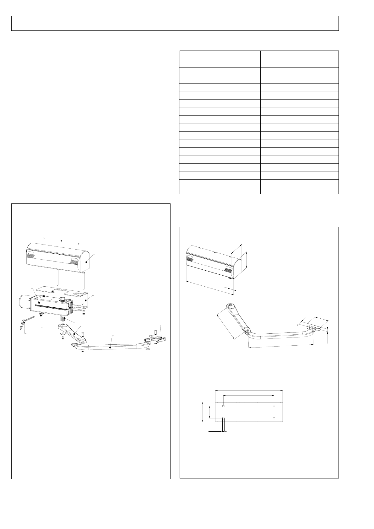
2. DIMENSIONS
8μF
15
960
1
5
2
6
4
3
7
1) Guard
2) Operator securing base-plate
3) Release wrench
4) Release
5) Gearmotor
6) Transmission shaft
7) Straight lever of articulated arm
8) Curved lever of articulated arm
9) Front coupling
130
130
410
9
8
100
Fig. 1 Fig. 2
•measurements in mm
60
Ø 1 0
60
390
332
250
480
45
115
21.5
2
Page 4

3. ELECTRICAL EQUIPMENT (standards system)
1) Operators mod. 390
2) Photocells
3) Electronic equipment
4) Key-operated push-button
5) Radio receiver
6) Flashlight
Notes: 1) To lay electrical cables, use adequate rigid and/
or flexible tubes.
2) Always separate low voltage accessories from
those operating at 230V~. To avoid any
interference, always use separate sheaths.
Fig. 3
4. INSTALLATION OF AUTOMATION
4.1. PRELIMINARY CHECKS
To ensure safety and an efficient automation, make sure the
following requirements are met:
• The gate structure must be suitable for automation. In
particular, make sure it is sufficiently sturdy and rigid, and
that its dimensions are in line with those indicated in the
technical specifications.
• Make sure that the leaves move properly and uniformly,
without any irregular friction during their entire travel.
• Check if hinges are in good condition.
• Make sure the travel limit mechanical stops are present.
• We advise you to carry out any metalwork jobs before
installing the automation.
4.2. INSTALLATION DIMENSIONS
Establish the installation position of the operator by consulting Fig.
4-5-6.
4.2.1. RECOMMENDED DIMENSIONS FOR INWARD OPENING
B C
X
A
40 / 60
α°
Notes: As for 120° openings the curved arm must be fixed
to the hole marked with the letter X
αα
α
A B C (max)
αα
60÷110 110÷130 730 90°
110÷160 110÷130 720 90°
160÷210 110÷130 710 90°
210÷260 110÷130 700 90°
260÷310 110÷130 690 90°
310÷360 110÷130 670 90°
60÷110 190÷210 650 120°
110÷160 230÷250 600 120°
160÷210 290÷310 540 120°
210÷260 310÷330 510 120°
•measurements in mm
Fig. 5
4.2.2. RECOMMENDED DIMENSIONS FOR OUTWARD OPENING
α
°
40 / 60
A
~ 41
~ 200
•measurements in mm
Fig. 4
•measurements in mm
3
CB
αα
α
A B C (max)
αα
60÷110 110÷130 430 90°
110÷160 110÷130 380 90°
160÷210 110÷130 330 90°
210÷260 110÷130 280 90°
260÷310 110÷130 240 90°
Fig. 6
Page 5

4.3. INSTALLATION STEPS
The operator 390, base-plate and articulated arm are designed
either for right-hand or left-hand (Fig. 7) installation.
SX
DX
Fig. 7
• Secure the base-plate to the pilaster, using Ø10 screws and
suitable expansion plugs (Fig. 8), and check it is perfectly
horizontal.
• Fit the gearmotor unit on the base-plate and secure it with
the two screws, nuts and flexible washers (Fig.8).
• The transmission shaft must always face downward.
SX
DX
Fig. 8
• Assemble the articulated arm and front coupling as shown
in Fig. 9.
SX
DX
Fig. 11 Fig. 12
• In both cases, provisionally remove the coupling from the arm
in order to secure it.
• Fit the guards on the operator (Fig. 10).
• Re-lock the operator (chapter 6.)
• Make the electrical connections of the selected electronic
appliance, observing the annexed instructions.
4.4. TEST OF THE AUTOMATION
When you have finished installation, carefully check the operating
efficiency of the automation and of all accessories connected
to it, safety devices in particular.
Hand the “User’s Guide” page to the Client, and describe how
the operator should function and be used correctly, stressing the
potentially dangerous areas of the automation.
5. MANUAL OPERATING MODE
If the gate has to be operated manually in the event of a powercut or fault to the automation, use the release device as follows:
• Fit the supplied Allen wrench and turn it by about a half turn
until it stops, in the direction shown in Fig. 13, depending on
type of installation.
6. RESTORING NORMAL OPERATING MODE
To avoid an involuntary pulse from activating the gate during the
manoeuvre, before re-locking the operator , switch off power to
the system.
• Fit the supplied Allen wrench and turn it by about a half turn
until it stops, in the direction shown in Fig. 13, depending on
type of installation.
Fig. 9
• Fit the straight lever of the articulated arm on the gearmotor
shaft and tighten it with the supplied screw and washer (Fig.
10).
• Release the operator (chapter 5.)
• Establish the securing position of the front coupling on the
leaf, observing dimension “C” defined previously (chapter
4.2). Check that arm and coupling are perfectly horizontal.
• The coupling may be welded directly onto the leaf (Fig. 11)
or screwed by using the threaded inserts (Fig. 12).
SX
DX
Fig. 10
DX
SBLOCCA / UNLOCK
DEBLOQUE / ENTRIEGELT
DESBLOQUEAR
BLOQUE / VERRIEGELT
BLOCCA / LOCK
BLOQUE / VERRIEGELT
BLOQUEAR
SX
SBLOCCA / UNLOCK
DEBLOQUE / ENTRIEGELT
DESBLOQUEAR
Fig. 13
7. MAINTENANCE
Do the following jobs at least every six months:
• Check if motor torque is correctly set.
• Check efficiency of the release system.
• Check efficiency of safety devices.
8. REPAIRS
For any repairs, contact our authorised Repair Centres.
BLOCCA / LOCK
BLOQUEAR
8
4
Page 6

End-user guide
AUTOMATION FAAC 390
Read the instructions carefully before using the product, and
keep them for future consultation.
GENERAL SAFETY REGULATIONS
If installed and used correctly, the automation 390 will ensure a
high degree of safety.
Some simple rules regarding behaviour will avoid any accidental
trouble:
- Do not pass through the leaves while they are moving. Before
passing through the leaves, wait until they are fully open.
- Do not, on any account, stand between the leaves.
- Do not stand near the automation and do not allow children
and other people to stand there, especially while it is operating.
- Keep remote controls or any other pulse generator well away
from children to prevent the automation from being activated
involuntarily.
- Do not allow children to play with the automation.
- Do not willingly obstruct movement of the leaves.
- Do not allow branches or shrubs to interfere with leaf movement.
- Keep illuminated signalling systems efficient and clearly visible.
- Do not attempt to activate the leaves manually unless you
have released them first of all.
- In the event of a malfunction, release the leaves to allow access
and wait for qualified personnel to take appropriate action.
- After enabling manual operating mode, switch off the power
supply to the system before restoring normal operating mode.
- Do not make any alterations to the components of the
automation.
- Do not attempt to repair or adjust the system personally, but
contact qualified personnel only.
- Call in qualified personnel at least every 6 months to check the
efficiency of the automation, safety devices and earth
connection.
DESCRIPTION
These instructions apply to the following model:
FAAC 390
FAAC 390 automation for residential swing-leaf gates consists of
an irreversible electro-mechanical operator with guard and an
articulated-arm activation system fitted to the gate with the
appropriate accessories.
The irreversible system ensures the gate is mechanically locked
when the motor is not operating. No lock need be installed for
leaves up to 1,8m in length.
A manual release makes it possible to move the gate in the event
of a power-cut or fault.
The operators are supervised by an electronic control unit,
housed in a container adequately protected against
atmospheric agents.
The leaves are normally in closed position.
When the electronic control unit receives an opening command
by remote control or by any other pulse generator, it activates the
operator to rotate the leaves until they are sufficiently open to
provide access.
If automatic operating mode was set, the leaves close on their
own after the selected pause time has elapsed.
If semi-automatic operating mode was set, a second pulse must
be sent to allow the leaves to close again.
A stop pulse (if supplied) always stops movement.
For detail on operation of the automation under different
operational logics, consult the installation technician.
The automations include safety devices (photocells, sensitive
edges,…) which prevent the leaves from moving when there is an
obstacle in the area they protect.
The automation 390 requires use of electronic appliances with an
electronic torque control device.
The light indicates that leaves are moving.
MANUAL OPERATING MODE
If the gate has to be operated manually in the event of a powercut or automation fault, use the release device as follows:
•Fit the supplied Allen wrench and turn it by about a half turn until
it stops, in the direction shown in Fig. 1-2, depending on type
of installation.
RESTORING NORMAL OPERATING MODE
To avoid an involuntary pulse from activating the gate during the
manoeuvre, before re-locking the operator, switch off power to
the system.
•Fit the supplied Allen wrench in the release device and turn it
by about a half turn until it stops, in the direction shown in Fig.
1-2, depending on type of installation.
•The release device can be activated without removing the
guard.
SX
BLOCCA / LOCK
BLOQUE / VERRIEGELT
DX
SBLOCCA / UNLOCK
DEBLOQUE / ENTRIEGELT
DESBLOQUEAR
BLOCCA / LOCK
BLOQUE / VERRIEGELT
BLOQUEAR
BLOQUEAR
SBLOCCA / UNLOCK
DEBLOQUE / ENTRIEGELT
DESBLOQUEAR
Fig. 1
Fig. 2
9
5
Page 7

QRWHQRWHVQRWHQRWDVDQPHUNXQJRSPHUNLQJHQ
6
Page 8

QRWHQRWHVQRWHQRWDVDQPHUNXQJRSPHUNLQJHQ
7
Page 9

QRWHQRWHVQRWHQRWDVDQPHUNXQJRSPHUNLQJHQ
8
Page 10

The descriptions and illustrations contained in this manual are not
The descriptions and illustrations contained in this manual are not
binding. FAAC reserve the right, whilst leaving the main features of
binding. FAAC reserve the right, whilst leaving the main features of
the main equipment unaltered, to undertake any modifi cations it holds
the main equipment unaltered, to undertake any modifi cations it holds
necessary for either technical or commercial reasons, at any time and
necessary for either technical or commercial reasons, at any time and
without revising the present publication.
without revising the present publication.
FAAC (UK) Limited, 6 Hamilton Close
FAAC (UK) Limited, 6 Hamilton Close
Houndmills Estate, Basingstoke, RG21 6YT
Houndmills Estate, Basingstoke, RG21 6YT
Telephone: 01256 318100
Telephone: 01256 318100
Fax: 01256 318101
Fax: 01256 318101
Email: sales@faac.co.uk
Email: sales@faac.co.uk
Website: www.faac.co.uk
Website: www.faac.co.uk
V3 01/07
V3 01/07
Your authorised FAAC dealer
Your authorised FAAC dealer
Your authorised FAAC dealer
 Loading...