

Page 1
ENGLISH
BA
C
24 Vdc ELECTRONIC CONTROL UNIT FOR SWING GATES
USE INSTRUCTIONS - INSTALLATION INSTRUCTIONS
This 24 Vdc control unit for swing gates offers high performance and a wide range of adjustments: opening and closing decelerations,
possibility of managing one or two motors, management of opening and closing limit-switches, and the possibility of managing two
GATECODERS.
A sophisticated electronic control constantly monitors the power circuit and disables the control unit in the event of malfunctions that
could impair efficiency of the electronic clutch.
The parameter settings and the operating logics are set and shown on a handy display, which indicates gate status during normal operation.
Operating times are adjusted by self-learning during programming.
The water-tight enclosure is designed to house the control unit, the toroidal transformer and any buffer batteries (optional) having the
characteristics and dimensions indicated in the table below.
2. TECHNICAL SPECIFICATIONS
1. GENERAL CHARACTERISTICS
remrofsnartfoegatlovylppuS .zH06/05-)%01-6+(~V511/032
wopdebrosbA W3
re
daolxamrotoM 2xW07
sesufnoitcetorP 4
scigolnoitcnuF
suaP gnimmargorpgnirudgninrael-fleshguorhT
emite
ecroftsurhT yalpsidnoelbatsujdaslevelruoF
snoitareleceD gnisolc
rotcennocoidaR rotcennocnip-5dipaR
blanimreT
snoisnemiddraoB .mm031x561
ATTENTION: Different output values can be obtained on the 24V~ voltage depending on the mains voltage value. Before start-up, always
check the transformer output voltage. This must not exceed 26V~ for both 230V~ and 115V~ power supply. Voltage must be measured
load free, i.e. with the transformer powered and disconnected from the board.
tinulortnocfoegatlovylppuS .zH06/05-)%01-6+(~V42
daolxamseirosseccA Am005cdV42
emitgnisolc/gninepO gnimmargorpgnirudgninrael-fleshguorhT
stupnidraoblanimreT
stuptuodrao
daol.xamthgilysetruoC/pmalgnihsalF .xamW51cd
erutarepmettneibmagnitarepO C°05+C°02-
deppetS/citamotuA
C
remrofsnartladiorot~V032foscitsiretcarahC AV021/~V22.ces/~V032.mirp
remrofsna
rtladiorot~V511foscitsiretcarahC AV021/~V02.ces/~V511.mirp
seirettablanoitpofoscitsiretcarahC .mm801x07x
erusolcneroodtuofoscitsiretcarahC 55PI-.mm521x522x503
V42
/citamotuaimeS
epytodnoC
dnagninepO
onairtsedeP/gninepolatoT
09.snemid/hA4-V21
hctiws-timilgnisolc-gninepO/potS/
deppetS/citamotuaimeS/citamotuA
redocnE/ylppusyrettaB/~V42ylppusrewoP
cdV42/srotoMcdV42/seirosseccaotylppusrewopcdV42
kcolcirtcelE~/cdV21/pmalgnihsalF-thgilysetruo
3. PRELIMINARY SETTING-UP
ATTENTION: To ensure people’s safety, all warnings and instructions in this booklet must be carefully observed. Incorrect installation or
incorrect use of the product could cause serious harm to people.
Make sure there is an adequate differential switch upstream of the system as specified by current laws, and install an all-pole thermal
breaker on the power supply mains.
To lay electric cables, use adequate rigid and/or flexible pipes.
Always separate the connection cables of low voltage accessories from the 115/230 V~ power cables. To prevent any interference
whatever, use separate sheaths.
Maximum length of power cables between control unit and motors must not exceed 10 m, using cables of 2.5mm2 diameter.
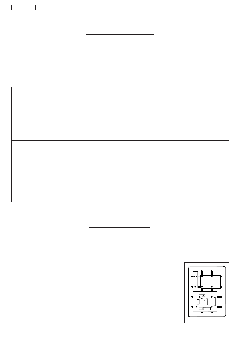
Procedure for securing components inside the water-tight enclosure.
1- Secure the support for the toroidal transformer in position A with 3 Ø4.2x13 self-tapping screws (supplied),
placing the supplied spacers between the transformer support and the guides of the water-tight enclosure.
2- Secure the transformer to the support with 2 clamps (supplied).
3- If using buffer batteries, secure the relevant support in position B with 4 Ø3.5x9.5 self-tapping screws
(supplied), fastening the screws in the crossover holes of the enclosure guides.
N.B.: the support is sized to house 2 batteries (not supplied) with the dimensions specified in the table in
paragraph 2.
4- Position the batteries on the support and secure them with plastic clamps.
5- Secure the control unit in position C with the 4 Ø4.2x13 self-tapping screws (supplied), placing the supplied
spacers between the control unit and the enclosure guides.
secivedytefasgnisolc-gninepO/gninep
10
Fig. 1
Page 2

ENGLISH
4. CONNECTIONS AND OPERATION
4.1. TERMINAL BOARD CN1
4.1.1. Power supply 22V
“VAC -VAC” terminals. The secondar y circuit of the 24V~ 50/60 Hz transformer should be connected to this input. Power supplied by the
transformer is signalled by the lighting of the “ALIM” LED located under the terminal board.
4.1.2. Batteries
“+BAT - -BAT” terminals. Connect the power cables of the buffer batteries (optional) to these terminals. The control unit is designed to
operate with two buffer batteries, with the minimum characteristics shown on the table in paragraph 2. During normal operation, the unit
keeps the batteries charged and these start operating if no power is supplied to the transformer.
N.B.:
• Power supplied by batteries only should be considered an emergency situation. The number of possible manoeuvres is linked to the
quality of the batteries, the structure of the gate to be moved, the time elapsed since power cut occurred, etc, etc.
• Observe the battery power supply polarity.
4.1.3. Accessories
“+24V - -24V” terminals. The accessories power cables should be connected to these terminals.
N.B.:
• The maximum load of the accessories must not exceed 500 mA.
• The output of these terminals is DC - observe the power supply polarity of the accessories.
4.1.4. Earth
“ “ terminal. The control unit earthing cable should be connected to this terminal.
N.B.:
• This connection is absolutely necessary to ensure a correctly operating control unit.
4.2. TERMINAL BOARD CN2
4.2.1. Gearmotor 1
“APM1 - CHM1” terminals. For double leaf applications, connect to these terminals the gearmotor fitted on the leaf which must move
first. For single leaf applications, the gearmotor must be connected to these terminals. The maximum load of the gearmotor must not
exceed 70W.
4.2.2. Gearmotor 2
“APM2 - CHM2” terminals. For double leaf applications, connect to these terminals the gearmotor fitted on the leaf which must move last.
For single-leaf applications, nothing should be connected to these terminals. The maximum load of the gearmotor must not exceed 70W.
4.2.3. Electric lock
“ELS - ELS”terminals. The electric lock, if any, with 12 Vdc/~ power supply, should be connected to these terminals. To facilitate release of
the electric lock, the over-pushing stroke can be input by enabling parameter “F” (see paragraph 9).
N.B.:
• In double-leaf applications, install the electric lock on the leaf where gearmotor 1 is installed.
4.2.4. Flashing lamp / Courtesy light
“LAMP - LAMP” terminals. Both a flashing lamp and a courtesy light can be connected to these terminals, both with 24 Vdc power supply
and maximum 15W. To make this output operational, select parameter “G”, see paragraph 9.
Flashing lamp operation:
During normal operation, the flashing lamp provides a fixed pre-flashing of 1.5 seconds during both opening and closing. When the gate
is open, and the closing safety devices are tripped, the lamp flashes to indicate that a manoeuvre is taking place in the gate movement
area. We advise you to connect the flashing lamp before programming, because it indicates its phases. Use a fixed light flashing lamp;
flashing is controlled by the control unit.
Courtesy light operation:
The courtesy light stays lighted for a fixed time of 90 seconds from the OPEN pulse, after which it goes OFF. Use a lamp with 24 V power
supply and maximum 15W.
4.3. TERMINAL BOARD CN3
4.3.1. Motor 1 closing limit-switch
“COMF - FCC1” terminals. Normally closed contact. This is tripped and stops the closing motion of motor 1. The status of this input is signalled
by LED FCC1.
4.3.2. Motor 1 opening limit-switch
“COMF - FCA1” terminals. Normally closed contact. This is tripped and stops the opening motion of motor 1. The status of this input is
signalled by LED FCA1.
4.3.3. Motor 2 closing limit-switch
“COMF - FCC2” terminals. Normally closed contact. This is tripped and stops the closing motion of motor 2.The status of this input is signalled
by LED FCC2.
4.3.4. Motor 2 opening limit-switch
“COMF - FCA2” terminals. Normally closed contact. This is tripped and stops the opening motion of motor 2. The status of this input is
signalled by LED FCA2.
N.B.:
• If no limit-switch is used, jumper connect the inputs.
• The limit-switches cannot be used as the start of the decelerated section.
4.3.5. Motor 1 encoder
“ENC1” terminal. The signal received from the encoder installed on gearmotor 1 must be connected to this terminal. For operation and
activation of the encoder, see paragraph 6.
N.B.: If no encoder is used, do not, on any account, jumper-connect the inputs.
11
Page 3

ENGLISH
ENCODER
OFF ON
AMPERO
3421
ON
ENCODER
OFF ON
AMPERO
3
421
ON
4.3.6. Motor 2 encoder
“ENC2” terminal. The signal received from the encoder installed on gearmotor 2 must be connected to this terminal. For operation and
activation of the encoder, see paragraph 6.
N.B.: If no encoder is used, do not, on any account, jumper-connect the inputs.
Attention: In two-motor applications, the encoder must be installed on both motors.
4.4. TERMINAL BOARD CN4
4.4.1. Total opening
“COM - OPEN A”terminals. Normally open contact. Connect, to these terminals, any pulse generator (e.g. push-button, key selector, etc.)
which, by closing a contact, generates a gate total opening or closing pulse. The operation of this generator is defined by parameter “D”,
see paragraph 9.
N.B.:
• A total opening pulse always has priority over pedestrian opening.
• To connect several pulse generators, connect the devices in parallel.
4.4.2. Pedestrian opening
“COM - OPEN B” terminals. Normally open contact. Connect, to these terminals, any pulse generator (e.g. push-button, key selector, etc..)
which, by closing a contact, generates a gate partial opening or closing pulse. In double leaf applications, pedestrian opening corresponds
to total opening of leaf 1. In single leaf applications, pedestrian opening corresponds to about 30% of memory-stored total opening.
N.B.:
• A total opening pulse always has priority over pedestrian opening.
• To connect several pulse generators, connect the devices in parallel.
4.4.3. Stop
“COM - STOP” terminals. Normally closed contact. Connect, to these terminals, any safety device (e.g. pressure switch, safety edge, etc.)
which, by opening a contact, immediately stops the gate and disables all automatic functions. The status of this input is signalled by the
“STOP” LED. The gate resumes its memory-stored cycle only by means of another total or partial opening pulse.
N.B.:
• If no STOP devices are connected, jumper connect the input.
• To connect several STOP commands, connect the devices in series.
4.4.4. Closing safety devices
“COM - FSW CL”terminals. Normally closed contact. Connect, to these terminals, any safety device (e.g. photocell, safety edge, pressure
switch etc..) which, by opening a contact, affects the gate's closing motion, reversing it to the mechanical stop, or to the opening limitswitch. The status of this input is signalled by LED “FSW-CL”.
4.4.5. Opening safety devices
“COM - FSW OP”terminals. Normally closed contact. Connect, to these terminals, any safety device (e.g. photocell, safety edge, pressure
switch etc..) which, by opening a contact, affects the gate's opening motion, causing it to stop immediately. When the safety device has
been reset, the gate resumes its memory-stored cycle. The status of this input is signalled by LED “FSW-OP”.
N.B.:
• If no safety devices are connected, jumper connect the inputs.
• To connect several safety devices, connect the devices in series.
The control unit is designed to house a 5-pin radio-receiver module. Installation procedure: turn off power and fit the module in connector
CN5 on the control unit.
ATTENTION: To avoid damaging the receiver and thus irreparably compromising its operation, the receiver must be installed while
observing the fitting direction specified in paragraph 13 (connection lay-out).
This done, observe the radio-receiver instructions to store the radio control in the memory.
6. OPERATION WITH ENCODER OR AMPEROMETRIC OPERATION
The control unit has 4 DIP SWITCHES, which enable selection of either amperometric operation or operation with Encoder.
Operation with encoder provides greater safety in detecting obstacles and greater repeatability of the deceleration point.
N.B.: Operation with encoder requires mechanical stops, or limit-switches, for both opening and closing.
To select operation with encoder, position DIP-SWITCHES 1 and 2 to ON and DIP-SWITCHES 3 and 4 to OFF (Fig.02).
To select amperometric operation, position DIP-SWITCHES 1 and 2 to OFF and DIP-SWITCHES 3 and 4 to ON (Fig.03).
ATTENTION: For a correct programming procedure of the control unit, carry out this operation before programming the control unit
because it radically modifies its operation.
Operation with Encoder Amperometric operation
Fig. 2
5. INSTALLING THE RADIO CONTROL RECEIVER BOARD
12
Fig. 3
Page 4

ENGLISH
7. CONTROL LEDS
SDELNOFFO
MILAremrofsnartladiorotybylppusrewoP deilppusrewoponroseirettabybdeilppusrewoP
1CCF deppirttonhcti
1ACFdeppirttonhctiws-timilgninepo1rotoM deppirthct
2CCF deppirttonhctiws-timilgnisolc2rotoM deppirthctiws-timilgnisolc2rotoM
2ACFdeppi
POTSdetavitcatondnammocpotS detavitcadnam
LC-WSFdeppirttonecivedytefasgnisolC deppirtecivedytefasgnisolC
PO-WSFdeppirttonecivedytefasgninepO
N.B.:
• Indicated in bold: status of LEDs with gate closed, control unit powered, and both limit-switches installed.
• If the limit-switches are not used, the relevant contacts must be jumper connected and LEDs FCC1 - FCA1 - FCC2 - FCA2 must be
lighted.
• If no STOP devices are connected, jumper connect the input. The STOP LED must be lighted.
ws-timilgnisolc1rotoM deppirthctiws-timilgnisolc1rotoM
iws-timilgninepo1rotoM
rttonhctiws-timilgninepo1rotoM deppirthctiws-timilgninepo2rotoM
mocpotS
deppirtecivedytefasgninepO
The control unit has a handy display for viewing and programming the operating parameters. Furthermore, it constantly shows gate status
during normal operation.
When operating parameters are being displayed and programmed, the display shows the selected
parameter on the left, and its set value on the right. Fig. 04 shows the viewing example of parameter “A”
at value “2”.
During normal operation, the display shows gate status. The displayed values are indicated on the following
table:
EULAVYALPSID SUTATSETAG
tsertaetaG
gninepoetaG
sesuapninepoetaG
gnisolcetaG
)hpargaraptxenees-delbaneerusolc-ercitamotuahtiwylnO(sutat
Fig. 4
9. ADJUSTING THE OPERATING PARAMETERS
N.B.: Before you begin adjusting the operating parameters, select the type of operation for the control unit: with or without encoder (see
paragraph 6).
To access operating parameter adjustment, follow the instructions below:
1- When you have made all the necessary connections, power up the system and check if all the signalling LEDs are in the situation
specified in paragraph 7.
2- The display shows value “ ”.
3- Press and hold down push-button P2 until the display shows the name and value of the first parameter.
4- Press push-button P1 to change the value of the parameter.
5- To move on to the next parameter, press push-button P2.
6- When 60 seconds have elapsed without any key being touched, the control unit exits the adjustment mode. You can manually exit
the adjustment mode by scrolling all the parameters with push-button P2. When the display shows value “ “, you have returned to
normal operation.
8. OPERATION OF DISPLAY
13
Page 5

ENGLISH
The following table summarises all settable parameters and the assignable values.
YALPSID NOITPIRCSED
hctulccinortceleehtfoytivitisnesehtgnitsujdA
ecrofrotommuminiM
ecrofrotomwol-muideM
ec
rofrotomhgih-muideM
ecrofrotomhgiH
:yaled2faeL .sevaelowtehtfoemittesffoehttcelesotuoyselbaneretemarapsi
ht
tesffosdnoces5.1
tesffosdnoces3
tesffosdnoces6
tesffosdnoces01
:erusolceRcitamotuA .erusolceretagcitamot
delbanE
itcnufodnoC .detibihnisidnammoctratseht,denepogniebsietagehtelihwdelbanesinoitcnufsihtfi
:no
E
delban
:ekortsgnihsuprevO gnisolcstistratsdellatsnisikcolcirtceleehthcihwnofaeleht,eslupNEPOyreveta,noitcnuf
delbanE
hsalF/thgilysetruoC gnitceles,slanimretPMAL-PMALehtmorftuptuofoepytehttcelesnacuoy,retemarapsihthtiw
areleceD .seulavtesowtehtmorfgnitceles,noitcesdetarelecedehtfohtgnelehttesotdesusiretemarapsiht
.seulavowt
hgiH
woL
iL .hctiws-timilehttuohtiwrohtiwnoitarepotcelesotuoyselbaneretemarapsiht
:srotomforebmuN sevaelowthtiwrofaelenohtiw:etagfoepytehttcelesotdesusiretemarap
delbasiD
:dnammocANEPOfonoitarepO .nottub-hsup)gninepolatot(ANEPO
.....snepO/sesolC/snepO
delbasiD
sihtelbaneuoyfi
delbasiD
:pmalgni
pmalgnihsalF
:egatnecreptniopnoit
:noitarepohctiws-tim
siht
hgilysetruocdnapmalgnihsalfgnomamorf
:esahpnoitarelecedgniruddeepS ehtmorftignitce
hctiws-timiltuohtiwnoitarepO
hc
tiws-timilhtiwnoitarepO
uaselbasidroselbanenoitcnufsiht
ehtforuoivahebehtsenimretednoitcnufsiht
......snepO/spotS/sesolC/spotS/snepO
.kcolcirtceleehtfoesaelersetatilicafsihT.sdnoceswefaroftnemevom
.t
)sdnoces09rofevitca(thgilysetruoC
gninepo
derots-yromemmumixamfo%04
gninepoderots-yromemmumixamfo%02
detcennocrotomenoylno,etagfael-elgniS
detcennocsrotomowt,etagfael-elbuoD
les,esahpnoitarelecedehtgniruddeepsrotomtesotdesusiretemarapsiht
14
Page 6

ENGLISH
10. PROGRAMMING
N.B.:
• Before you begin programming, select the type of operation for the control unit: with or without encoder (see paragraph 6).
During the programming procedure, the control unit memory-stores the opening, closing mechanical stop points and any pause time
before re-closure.
1- Release the gearmotors, locate the leaves at half open point, and re-lock the operators.
2- Power up the control unit and check if value “ ” is shown on the display.
3- Press and hold down push-button P2 until the display shows the first parameter and relevant value.
4- Give an OPEN A command with any device connected to this input: the display shows value “ ”, and the leaves begin to move.
The first manoeuvre performed by the leaves must be closing. If this does not happen, stop the gate movement with a reset pulse. To
do this, make a bridge between the two “RESET” PINS, using the connector (see Fig.5). Cut
power and put the connector back in its normal position (Fig. 5). Then change over the
wires of the motor/s, which had performed the opening operation. Resume the
programming stage from point 1.
5- When the closing mechanical stop point is reached, the gearmotors pause for about 2
seconds, and then restart with a total opening manoeuvre up to the opening mechanical
stop point or up to the relevant limit-switch.
6- If automatic reclosure was not enabled, this means programming has finished, otherwise
the control unit begins counting pause time.
7- When the required time has elapsed, give another OPEN A pulse, and the gate will begin
to close.
8- When the closing stop has been reached, programming has terminated, and the display
shows value “ ”.
N.B.:
• The display shows value “ ” during the entire programming procedure.
• The flashing lamp stays lighted on a fixed light during the entire programming time.
• Leaf movement is decelerated during the programming procedure.
Fig. 5
This is a very important device for reasons of safety. Its setting stays unchanged long-term, without wear. It is active during both closing and
opening. When it operates, it reverses gate movement without disabling automatic closing if activated.
If the clutch operates several consecutive times during the closing movement, the control unit goes into STOP status, disabling any
automatic command. If the clutch operates several consecutive times, this means that the obstacle remains and it could be dangerous
to perform any manoeuvre. To restore normal operation, the user must give an OPEN A / OPEN B pulse.
12. PROTECTION FUSES
ESUFNOITCETORPESUFNOITCETORPESUFNOITCETORPESUFNOITCETORP
oty
11. OPERATION OF ELECTRONIC CLUTCH
1F A01T=
02x5-V052
ylppusrewoP
~V42
2F A36.0T=
02x5-V052
lppuS
seirossecca
3F A36.0R=
-yrettabdna
regrahc
02x5-V052
pmalgnihsalF
4F A51.3R=
tuptuo
02x5-V052
kcolcirtcelE
uptuo
t
15
Page 7

ENGLISH
13. CONNECTION LAY-OUT
Batteries
Toroidal transformer
230 V~
50 Hz
Power supply for external
+
VAC
VAC
+24V
+BAT
-BAT
F1
Motor 1
Electric lock 12V
accessories
-
-24V
ALIM
CN2
APM1
M1
Motor 2
Earthing
CN1
CHM1
M2
APM2
CHM2
ELS
ELS
F3
LAMP
LAMP
Flashing lamp
Courtesy light
Motor 2 encoder
Motor 1 encoder
COMF
F2
DS1
P1
RST
DS2
G
FD
M
N
2003/4/5
6/7/8/9
A
O
P2
10/11/12
M
S
G
A
L
AMPERO
ON
ENCODER
OFF
ON
3421
JMP1
F4
STOP
FSW-OP
A
ENC2
OPEN
ENC1
+
-
24V dc
-
RX-OP
1
2
3
4
+
5
TX - OP/CL
1
+
2
OPEN
B
DL6
STOP
FSW-CL
DL7
CL
FSW
DL8
CN4
OP
COM
TX-OP
+
TX - OP/CL
+
CN5
1
2
1
2
3
4
5
FCA2
FCA1
FCC1
FCC2
DL5
DL3
DL2
DL4
CN3
FCC2
FCC1
FCA2
FCA1
+
24V dc
-
24V
+
dc
24V
-
+
dc
Receiver
Connector for
5-pin receiver
Closing safety
devices
Opening safety
devices
Opening /closing
safety devices
-
+
24V dc
24V
-
+
dc
24V dc
-
+
RX-CL
1
2
3
4
-
5
+
TX - CL
+
-
1
24V dc
+
2
16
Page 8

ENGLISH
sesolc,desaelernehw
dna,emitesuapskcoL
dnanoitarepospotS
dnanoitarep
esaelernosemuser
esaelernosesr
.ces
5retfa
ospotS
ever
sesolc,desaelernehw
dna,emitesuapskcoL
.ces
5retfa
dnanoitarepospotS
dnanoitarepos
esaelernosemuser
esaelernosesrever
potS
14. FUNCTION LOGICS
,
esaelernO.erusolcspotS
despalesahemitesuap
fi,.ces5retfasesolc
tceffeoN
sdnammocNEPOselbas
dnanoitarepospotS
esaelernosemuser
,
esaelernO.erusolcspotS
despalesahemitesuap
fi,.ces5retfasesolc
tceffeoN
sdnammocNEPOselbas
dnanoitarepospotS
esaelernosemuser
0=E1=d1=Ccigol"PA"citamotuAdeppetS
0=E0=d1=Ccigol"A"citamotuA
iDtceffeoNsdnammocNEPOselbasiD
)delbasidNEPO(
noitarepospotStceffeoN
tceffeoN
sesolc-erdnagninepo
laitrapfaelsetucexE
emitesuapretfa
etagehtsesolC
yletaidemmi
iDtceffeoNsdnammocNEPOselbasiD
)delbasidNEPO(
noitarepospotStceffeoN
tceffeoN
sesolc-erdnagninepo
laitrapfaelsetucexE
emitesuapretfa
etagehtsesolC
yletaidemmi
tceffeoNnoitarepospotStceffeoNnoitomsesreveR
tceffeoNnoitarepospotS
-erdnafaelehtsnepO
emitesuapre
AnepOBnepOpotSsecivedytefasgninepOsecivedytefasgnisolCecivedytefasLC/PO
tfasesolc
sutatsetaG sesluP
esuapnonepO emitesuapsdaoleR
desolC
gnisolC noitometagsesreveRtceffeoNnoitarepospotStceffeoNnoitomsesreveR
17
sutatsetaG sesluP
gninepO noitometagsesreveRtceffeoNnoitarepospotS
-erdnafaelehtsnepO
emitesuapretfasesolc
AnepOBnepOpotSsecivedytefasgninepOsecivedytefasgnisolCecivedytefasLC/PO
desolC
dnanoitometagspotS
dnanoitometagspotS
esluptxennosnepo
esluptxennosesolc
esuapnonepO emitesuapsdaoleR
gninepO
gnisolC
Page 9

ENGLISH
sesolc
dnammocNEPOselbasiD
-er,esaelerno,dna
dnanoitarepospotS
dnan
esaelernosemuser
esaelernosesrever
..ces5retfa
oitarepospotS
sesolc
dnammocNEPOselbasiD
dnanoitarepospotS
dnanoitarepospotS
esaelernosemuser
esaelernosesrever
-er,esaelerno,dna
..ces5retfa
sesolc,desaelernehw
dna,emitesuapskcoL
dnanoitarepospotS
dnanoitarepospotS
esaelernosesr
.ces
5retfa
esae
lernosemuser
ever
sesolc-er,esaelerno,dna
dnammocNEPOselbasiD
..ces5retfa
sdnammocNEPOselbasiDtceffeoNsdnammocNEPOselbasiD
tceffeoN
tceffeoN
dnanoitarepospotS
esaelerno
sesolc-er,esaelerno,dna
dnammocNEPOselbasiD
itometagsesreveR
..ces5retfa
sdnammocNEPOselbasiDtceffeoNsdnammocNEPOselbasiD
tceffeoN
tceffeoN
dnanoitarepospotS
esaelernosemuser
,
esaelernO.erusolcspotS
despalesahemitesuap
fi,.ces5retfasesolc
tceffeoN
sdnammocNEPOselbas
dnanoitarepospotS
esaelernosemuser
0=E1=d0=Ccigol"PE"citamotua-imeSdeppetS
0=E0=d0=Ccigol"E"citamotua-imeS
semuser
1=E0=d1=Ccigol"D"odnoC
)delbasidNEPO(
)delbasidNEPO(
tceffeoN
tceffeo
N
cexE
)delbasidNEPO(
)delbasidNEPO(
tceffeoN
tceffeo
N
tceffeoNnoitarepospotStceffeoNno
tceffeo
NnoitarepospotS
cexE
iDtceffeoNsdnammocNEPOselbasiD
)delbasidNEPO(
noitarepospotStceffeoN
tceffeoN
sesolc-erdnagninepo
laitrapfaelsetucexE
emitesuapretfa
etagehtsesolC
yletaidemmi
dnanoitarepoetagspotS
dnanoitarepoetagspotS
esluptxennosnepo
esluptxennosnepo
AnepOBnepOpotSsecivedytefasgninepOsecivedytefasgnisolCecivedytefasLC/PO
sutatsetaG sesluP
desolC faelehtsnepOgninepolaitrapsetu
nepO sesolCetagehtsesolC
gninepO noitometagsesreveRtceffeoNnoitarepospotS
gnisolC noitometagsesreveRtceffeoNnoitarepospotStceffeoNnoitometagsesreveR
AnepOBnepOpotSsecivedytefasgninepOsecivedytefasgnisolCecivedytefasLC/PO
sutatsetaG sesluP
desolC faelehtsnepOgninepolaitrapsetu
nepO sesolCetagehtsesolC
18
gninepO
gnisolC
-erdnafaelehtsnepO
emitesuapre
AnepOBnepOpotSsecivedytefasgninepOsecivedytefasgnisolCecivedytefasLC/PO
tfasesolc
sutatsetaG sesluP
esuapnonepO emitesuapsdaoleR
gninepO tceffeoNtceffeoNnoitarepospotS
desolC
gnisolC noitometagsesreveRtceffeoNnoitarepospotStceffeoNnoitomsesreveR
 Loading...