

Page 1
HYDRAULIC
SLIDE GATE
Operators
With Smart Touch Controller
Installation and Reference Manual
Models
DC Battery, Modular, Correctional Facility, and Solar versions of most models
* SlideDriver 50VF models use Installation and Reference Manual D0125. This can be downloaded at
SlideDriver 10
SlideDriver 40
SlideDriver 30F
SlideDriver 50VF2*
SlideDriver 50VF3*
SlideDriver 80
SlideDriver 200
(222 SS) Standard
(222 E) Heavy gates
(222 EX 1.7) Heavy, fast gates
(222 X2) Heavier, fast gates
(222 X3) Heavier, fastest gates
(222 X1) Very heavy gates
(444 XS) Ultra heavy gates
www.hysecurity.com.
D0119, Rev. F
Page 2

Installation and Maintenance Manual
SlideDriver Quick Start
These instructions are provided as a quick reference guide to the experienced installer that is already familiar with
all safety precautions and the installation of this gate operator. Do not attempt to install from this guide if you are
inexperienced with this product.
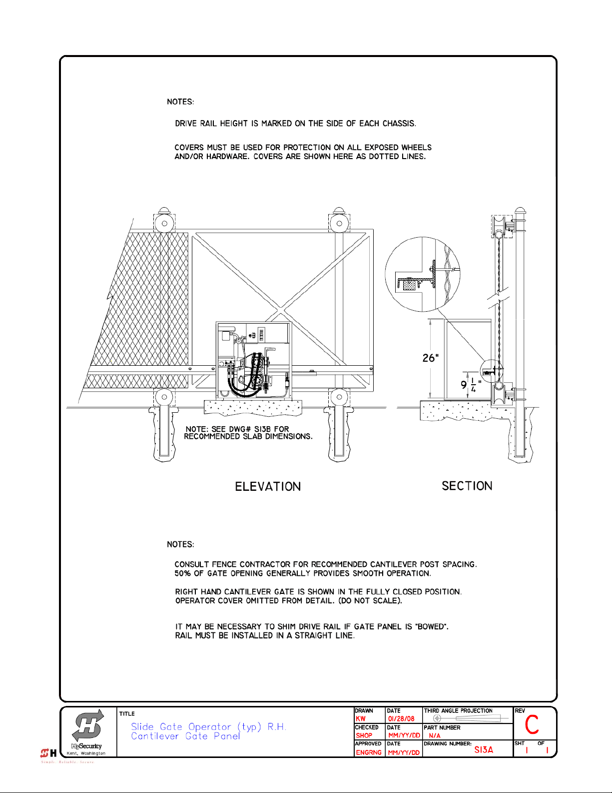
1. Mount the operator with at least four mounting bolts. The operator must be square and spaced 1¾” away
from the gate.
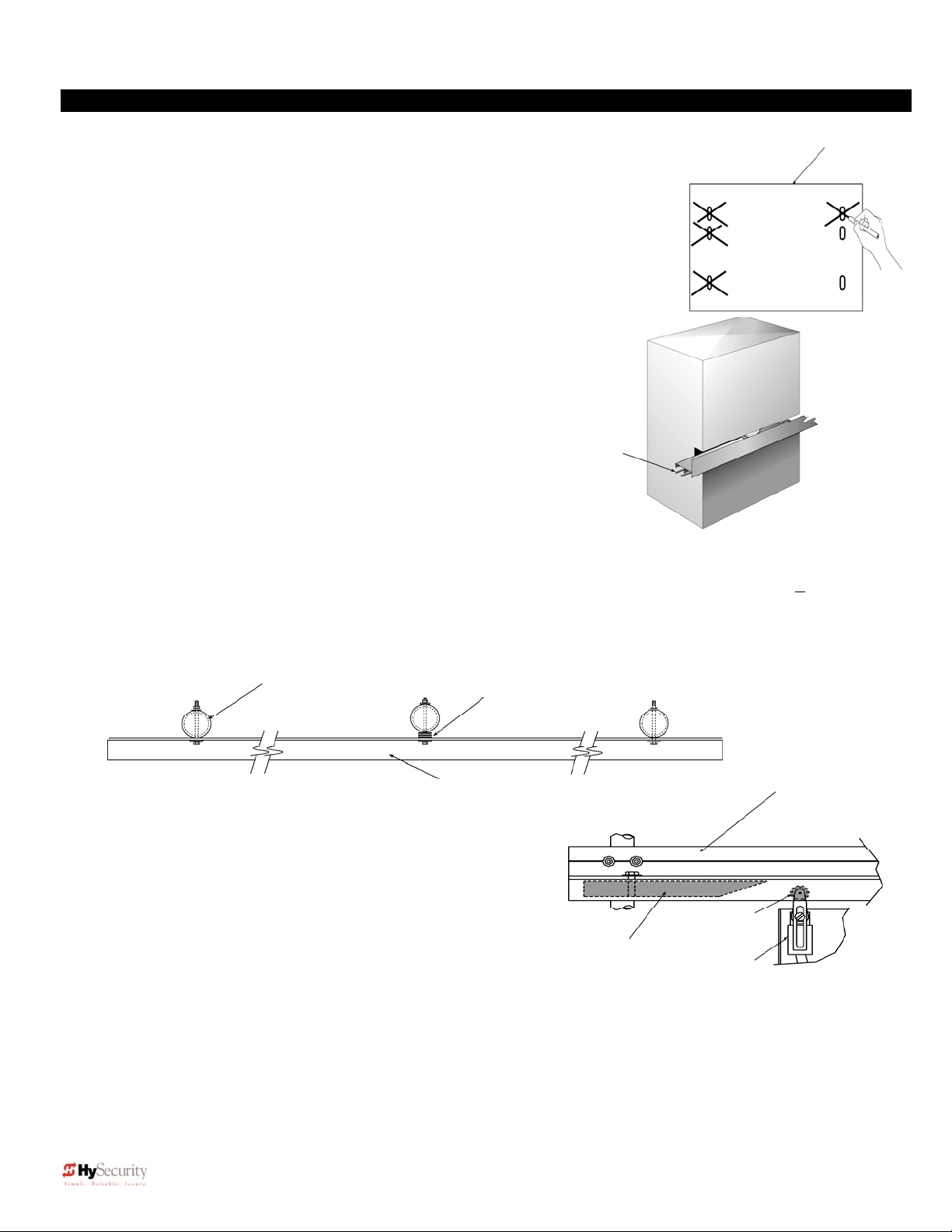
2. Attach the drive rail to every vertical member of the gate at a height 9 1/4“ above the base of the operator.
Use ¼” roll pins to splice multiple sections of rail.
3. Mount the limit switch trip ramps to the underside of the drive rail at each end. Drill 3/8” holes in a position
that will allow the limit switches to be tripped 6-8” before full travel.
4. Connect the electrical power and grounding wire to the loose wires from the On/Off switch at the left corner
of the control box. Be certain the labeled voltage and phase of the operator matches the available supply.
5. Operators are shipped configured for “right hand” operation. (From the secure side, the gate moves to
right on opening). To change the handing, reconnect the hydraulic hoses at the pump in reverse order.
There is a label near the hose connection point describing this procedure. Connecting the hose from the
top motor to the left disconnect results in “left hand” operation
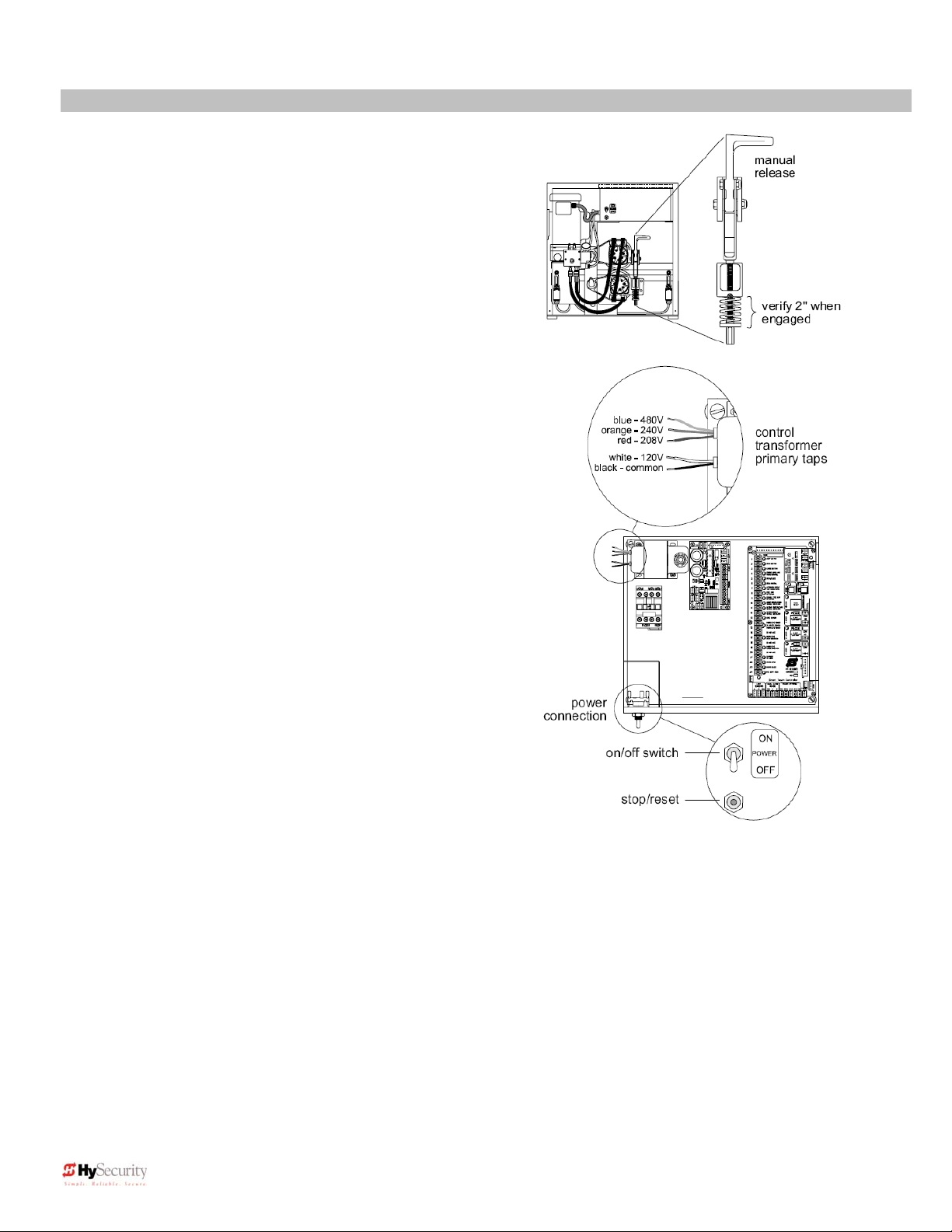
6. With neither limit switch tripped, engage the release mechanism to clamp the wheels to the drive rail and
verify that the red spring is compressed to 2” in height.
7. Turn on the power switch. The Smart Touch LCD display should show, after a 2 second delay, the
characters [uC_0]. This is a setting for the UL user class that must be made before any gate function will
be possible. Press the Select button, then the Next button and change the 0 to be class 1-4 as
appropriate for the site. Press the Select button again to lock the setting.
8. Press the Next button to go to the setting for the gate hand. The LCD display should now show [Sh_0].
The 0 must be replaced by an [Sh L] or [Sh r] before any gate function will be possible.
9. Press the Menu button and the display will jump to the close timer setting [Ct_0]. If a close timer function
is needed, set in the same manner as above. Press the Menu button again to exit to the Run Mode. The
LCD display should now read StoP, but may read oPEn or CloS if any limit switch is tripped.
10. Test the normal operation of the gate. If the hoses are connected incorrectly, the gate will move the wrong
direction. (see step 5). If the gate moves the correct direction, but triggers an Err1 alert, the handing is set
wrong. (see step 8).
11. After normal function has been verified, connect any required accessory device wiring. Note that the
control inputs (Except Fire Department Open and Emergency Close) are all one wire only to the main
terminal strip while the other wire connects to the Common Buss on the nearby power supply board.
12. To access the User menu in the Smart Touch Controller, press the Menu button while there is no active
Open or Close input. The display will scroll system values and stop at the [Ct__] close timer setting.
There are 11 menu items in the User Menu. To reach the more detailed Installer menu, the system must
be in the User Menu first, then simultaneously press Open and Reset. The display will go to [uC__] which
is the first of 34 items in the Installer Menu. Read the instructions before attempting any adjustments!
ii D0119, Rev. F
Page 3

Installation and Maintenance Manual
Smart Touch Controller Menu Guide for Sliding Gates
To gain access to the User Menu, press the Menu button when the gate is stopped. The LCD will
scroll through several key items, then stop at the close timer setting [Ct ].
User Menu Options Default Description
U1
[Ct 0] Close timer setting 0 0 = close timer off or 1 – 99 seconds
U2
[hC 0] Momentary Close 0 0 = momentary, 1= Constant hold PB required to close gate
U3
[ho 0] Momentary Open 0 0 = momentary, 1= Constant hold PB required to open gate
U4
[AP 0] Power loss function 0 0 – 3 (0 =Type A, 1 = B, 2 = C, 3 = D) See handbook
U5
[ro 0] Radio control option 0 0 = Open only, 1 = Adds Close capability when fully open
U6
[bF 2] Warn before operate 2 0 = none, 1 = Buzzer alerts 3 sec before & when in motion,
2 = Buzzer alerts 3 sec before + first 2 seconds in motion
U7
[FA 0] Forced open Alert and
automatic gate reposition
U8
[dA 0] Drift Closed Alert and
automatic gate reposition
U9
[PE 0] Photo Eye Align Mode 0 0 = off, 1 = on (auto off when close limit triggered)
U10
[CL 0] Clock set (24 hour type) 0 0= display, 1= set mins, 2= set hours, 3= set day, 4= month
U11
[Ld 5] LCD Contrast set 5 1 - 9 = Adjusts contrast of the display
U12
[dS 0] Data Log (New Gen only) 0 0 = Std. 1 = Extended (resets automatically to 0 in 24 hr)
To access Installer Menu, press the Open & Reset buttons together while in the User Menu.
Installer Menu Options Default Description
I1
[uC 0] Set UL Usage Class 0 0 = gate disabled, Set Class 1 through 4 use
I2
[Sh 0] Set Handing of gate 0 0 = gate disabled, r = Right Hand, L = Left Hand
I3
[Fd 0] Load Factory Defaults 0 0 = User settings, 1 = Load defaults (resets entire menu)
I3a
[bu 0] Choose Buzzer Type 0 0 = Buzzer not set, 1 = Freq 1, 2 = Freq 2
I4
[dg 0] Set Master/Slave type 0 0 = Solo operator, 1 = Slave unit, 2 = Master unit
I5
[Ch 0] Set AC Charger or Solar 0 0 = DC + AC charger 1 = DC + Solar charger
I6
[Fo 0] Enable Fire Dept. Open 0 0 = input disabled, 1 = enabled
I7
[oC 0] Enable Emergency close 0 0 = input disabled, 1 = enabled
I8
[SE 3] Inherent Sensor sensitivity 3 1 = Maximum sensitivity, 9 = Lowest sensitivity
I9
[SS 0] Inherent Sensor function 0 1 = stop only (note, functions in usage class 4 only)
I10
[LC 0] Leaf delay Close 0 0 = none (1-7) ½ second steps (Master/slave only)
I11
[Lo 0] Leaf delay Open 0 0 = none (1-7) ½ second steps (Master/slave only)
I12
[rt 0] Maximum run timer 0 0 = 60 Seconds max run, 1 = 300 Seconds max run
I13
[Po 0] Partial Open distance 0 0 = input disabled, or 7 – 99 seconds of travel
I14
[EC 0] PEC reverse to open 0 0 = Close eye stops only, 1 = 2 sec reverse to open
I15
[EO 0] PEO reverse to close 0 0 = Open eye stops only, 1 = 2 sec reverse to close
I16
[gr 0] Edge reverse to open 0 0 = Edge reverses fully open, 1 = Edge reverses for 2 sec
I17
[Sr 1] IES reverse to open 1 0 = IES reverses fully open, 1= IES reverses for 2 sec
I18
[PC 0] Set PEO/ PEC – NO/NC 0 0 = Normally Open PE output, 1 = N.C. (Supervised mode)
I19
[gC 0] Set Edge input – NO/NC 0 0 = Normally Open Edge output, 1 = Normally Closed
I20
[tC 1] Time clock/ Interlock input 1 0 = select Time Clock, 1 = select Open Interlock
I20a
[dt 0] Disable Free Exit/Timer to Close 0 0 = disable Free Exit, 1 = disable Close Timer
I21
[or 1] OOLD detector function 1 0 = pause closing only, 1 = enable reversing to open
I22
[ir 1] IOLD detector function 1 0 = pause closing only, 1 = enable reversing to open
I23
[dL 1] Vehicle detector logic 1 1 = std, 2 & 3 = quick close, 4 = full anti-tailgate logic
I24
[r1 0] User relay 1 option 1 0 = disabled, 1 – 24 = see output options page
I25
[r2 0] User relay 2 option 6 0 = disabled, 1 – 24 = see output options page
I26
[r3 0] User relay 3 option 1 0 = disabled, 1 – 24 = see output options page
I27
[tL 0] Gate Open alert 2 0 = 0 sec, 1 = 15s, 2 = 45s, 3 = 75s, 4 = 105s, 5 = 135s
I28
[Lt 0] Loitering alert 3 0 = 0 sec, 1 = 15s, 2 = 45s, 3 = 75s, 4 = 105s, 5 = 135s
I28a
[SA 0] System Address 0 0 = no network, 1-99 = network “drop” address
I29
[ELd0] Test factory ELD 0 0=Run, 1=show freq, 2=show call level 0-7, 3= set Freq 1-4
I30
[iLd0] Test factory IOLD 0 0=Run, 1=show freq, 2=show call level 0-7, 3= set Freq 1-4
I31
[oLd0] Test factory OOLD 0 0=Run, 1=show freq, 2=show call level 0-7, 3= set Freq 1-4
I32
[SLd0] Test factory SLD 0 0=Run, 1=show freq, 2=show call level 0-7, 3= set Freq 1-4
0 0 = disabled, 1 = sound buzzer (2 pulses/sec) if forced
open for more than four seconds, time out in 30 Sec
0 0 = disabled, 1 = sound buzzer (2 pulses/sec) if drift closed
and cannot reopen within four seconds.
(V4.xx software)
iii D0119, Rev. F
Page 4
Installation and Maintenance Manual
Ultra Reliable, Heavy Duty,
Commercial, Industrial, High Security
Slide Gate Operators
©Copyright 2006 Hy-Security Gate Inc.
All rights reserved. No part of this manual may be reproduced by any means: photocopier, electronic or mechanical, without
the express written permission of Hy-Security Gate Inc. Additionally, Hy-Security Inc. makes no representations or warranty
with respect to this manual. We also reserve the right to make changes in the products described without notice and
without any obligation to notify any persons of any such revision or change
.
iv D0119, Rev. F
Page 5

Installation and Maintenance Manual
Table of Contents
Introduction ....................................................................................................................vii
Warranty Registration...................................................................................................viii
Available Models and Features……………………………………………………………...1-2
I. Safe Gate Design
Important Information......................................................................................................3
Entrapment Protection Schematic..................................................................................4
Install an Automatic Operator only When: ....................................................................5
Important Instructions for Gate System Owners & Users ............................................6
II. Installation
Tools Required – Getting Started with an Automated Gate System.........................7-8
Installation Preparations and Installation .................................................................9-12
Mechanical & Hydraulic Adjustments ..........................................................................13
Technical Drawings...................................................................................................14-16
III. Smart Touch Set up
Basics of Using the Smart Touch Controller..........................................................17-18
Installation Configuration for Smart Touch Controller ...............................................18
Wiring Control Inputs to the Smart Touch Controller............................................19-20
Connecting a Master/Slave Pair or an Interlocked Pair ..............................................21
Table of User and Installer Menu Functions...........................................................22-23
User Menu: Description Functions Available..............................................................24
Installer Menu: Description Functions Available....................................................25-26
Correctional Facility – User Optional Wiring ...............................................................27
Options for User Programmable Output Relays.....................................................28-29
Setting the Time and Date on the Clock.......................................................................29
IV. Entrapment Protection
Entrapment Protection Schematic................................................................................30
UL 325 Standard Requirements for Entrapment Protection Devices ........................31
Placement and Use of Secondary Pedestrian Entrapment Sensors..........................32
Installing Gate Edge (Contact Type) Reversing Sensor .............................................33
Installing Photoelectric (Non-Contact) Sensor.......................................................34-35
v D0119, Rev. F
Page 6

Installation and Maintenance Manual
Table of Contents, cont.
V. Detectors and Loops
Detector Loop Installation Guide ............................................................................36-38
Vehicle Detector Installation & Adjustment Options..................................................39
HySecurity HY-5A Vehicle Detector Installation.........................................................40
Standard 11 Pin Vehicle Detector Installation ............................................................41
Vehicle Detector & Loop Fault Diagnostics................................................................42
Vehicle Detector Configuration and Anti-Tailgate Modes…......................................43
VI. Accessories
24 Hr / 7 Day Time Clock Option.................................................................................44
Radio Remote Open Option.........................................................................................45
Remote Release Option...............................................................................................46
Internal Solenoid Lock Options .............................................................................47-49
VII. Troubleshooting and Maintenance
Troubleshooting.......................................................................................................50-51
General Maintenance...............................................................................................52-53
Manual Release Mechanism.........................................................................................54
VIII. Two part Operators (Battery types & 333)
Battery DC Systems (DS, DE, DX)
Important Notes about DC Powered Gate Operators ...............................................55
Wiring & Control of DC Operators..............................................................................56
Plan and Elevation for DC Power Supply...................................................................57
Battery Supply Diagram ..............................................................................................58
Modular Systems (333 MS Series).........................................................................59-60
IX. Appendix
Wiring Size Schedules.............................................................................................61-62
444 Operator Components & Footprint.......................................................................63
Components & Replacement Parts ........................................................................64-70
Smart Touch Controller Electrical Connections........................................................71
SlideDriver Wheel Change Procedure ...................................................................72-73
Limited Warranty...........................................................................................................74
vi D0119, Rev. F
Page 7

Introduction
Welcome – Thank you for purchasing our HySecurity premium gate operator.
HySecurity has manufactured the finest hydraulic gate operators available
since the 1970s. Our commitment to quality and innovation will become
evident as you become familiar with the features and performance of this
expertly engineered machine. All HySecurity operators are equipped with the
Smart Touch Controller, a digital electronic brain that offers unparalleled user
benefits.
Please take a few minutes to study the contents of this instruction manual.
The benefits of taking a little extra time to align the gate operator properly and
to verify a fully functional installation will ensure customer satisfaction and a
longer life with minimal maintenance costs.
Installation and Maintenance Manual
Installers and owners must thoroughly review and
understand the important Information regarding
pedestrian entrapment protection contained in this
manual. There are hazards associated with automatic
gates that can be greatly reduced with proper design,
installation and use. When an automatic gate is first commissioned,
the installer must teach their owners and users how to correctly
operate this system. When the installation is complete, installers
should leave this manual for the owner’s use and reference.
Do not hesitate to give your HySecurity distributor a call if you experience any
installation difficulties. Authorized HySecurity distributors are experienced and
trained to assist in resolving any problems.
vii D0119, Rev. F
Page 8

Installation and Maintenance Manual
OPERATOR BULLETIN / WARRANTY REGISTRATION
Fill out this form to register this operator(s). HySecurity distributes frequent
maintenance, upgrade and Technical Bulletins to those who register their
operators. Fax or mail this completed form to HySecurity.
Date: ___________
Owner Name / Company: ___________________________________
Email: __________________________________________________
Address: ________________________________________________
City, State, Zip: ___________________________________________
Telephone number: ________________________________________
HySecurity Distributor: _____________________________________
Telephone Number: _______________________________________
Installer Name: ___________________________________________
Telephone Number: _______________________________________
Serial number of operator: ___________________________________
Date Installed: ____________________________________________
Operator Model: ________________________________________
Warranty Registration
HySecurity Mailing Address:
6623 South 228
Kent, WA 98032
FAX: (888) 321-9946
info@hysecurity.com
Technical Support: Call your installer or authorized HySecurity distributor for front line
technical support. Call HySecurity at 800-321-9947 with the serial number of your
operator and we will provide you with the name of your distributor.
Training: HySecurity provides regular installation, maintenance and troubleshooting
training. Go to www.hysecurity.com/support
more information regarding HySecurity tech training.
th
Street
or call HySecurity at 800-321-9947 for
viii D0119, Rev. F
Page 9
Installation and Maintenance Manual
SlideDriver Models
HySecurity manufactures many hydraulic slide gate operator models to suit the desired gate panel size,
weight and speed. All of the operator models are derived from the SlideDriver 10, upon which this manual is
designed. Identify your operator model and note the changes in instructions and final adjustments.
General
Gates
Duty
Part
Number
Modular
Prison
24V UPS
Solar
HP
Speed
Soft Stop
Brake
Valves
Soft Start
Drawbar
Pull
Weight
Capacity
Drive
Wheels
UL Class
Warranty
SlideDriver
10
Commercial
industrial,
high security
Lighter gates
Continuous
222 SS 222 E 222 EX 1.7 222 X2 222 X3 222 X1 444 XS
10-M 40-M 30F-M 50VF2-M 50VF3-M 80-M 10-C 40-C 30F-C 50VF2-C 50VF3-C 80-C 200-C
10 UPS 40 UPS 30F UPS - - 80 UPS 200 UPS
10-S 40-S 30F-S - - 80-S 200-S
1 hp 1 hp 2 hp 2 hp 2 hp 2 hp 5 hp
12” / sec. 12” / sec. 20” / sec. 26” / sec. 36” / sec. 12” / sec. 12” / sec.
yes yes yes yes yes yes yes
no yes yes yes yes yes yes
no no yes
300 lbs. 300 lbs. 300 lbs. 300 lbs. 300 lbs. 600 lbs. 1,200 lbs.
1,000 lbs. 4,000 lbs. 3,000 lbs. 5,000 lbs. 5,000 lbs. 8,000 lbs. 20,000 lbs.
2, 6” drive
wheels
I, II, III, IV I, II, III, IV III, IV III, IV III, IV III, IV III, IV
5 years 5 years 5 years 5 years 5 years 5 years 5 years
*SlideDriver 50VF models use Installation and Reference Manual D0125. Download at
www.hysecurity.com.
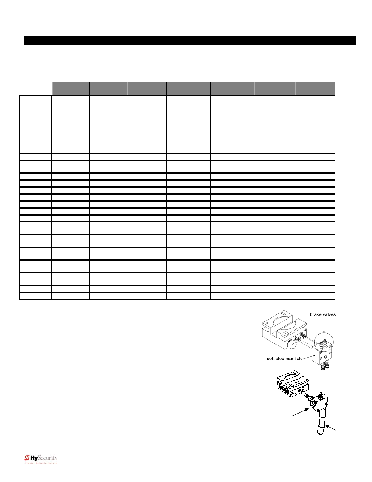
Stopping the Gate
All models employ a time delay Soft Stop system. Additionally, brake valves
are used to control the stopping of heavy or fast moving gates. These valves
are exclusive to HySecurity operators. They are independently adjustable to
allow the gate to stop predictably and without banging.
Starting the Gate
When starting very heavy gates beyond one foot per second, it is necessary to
Soft Start the load gently, in addition to stopping it smoothly. HySecurity
accomplishes Soft Start with another exclusive feature we call an Accumulator
With Out Gas (AWOG), which diverts some of the start-up hydraulic flow and
thereby allows the gate to accelerate over a period of about 2 seconds. This is
much like letting your foot slowly off a car clutch – no lurching when the gate starts.
The downward facing AWOG (shown right) improves the life and performance of a
gate system and never needs adjustment.
NOTE: Operators purchased prior to May 2008 may be equipped with an upward facing AWOG
hose which may periodically require “bleeding” the air pockets from the hose.
SlideDriver
40
Commercial
industrial,
high security
Heavier gates
to 4,000 lbs.
Continuous Continuous Continuous Continuous Continuous Continuous
2, 6” drive
wheels
SlideDriver
30F
Commercial
industrial,
high security
Heavier gates
(3,000 lbs.)
and faster (20
inches/sec.)
2, 6” drive
wheels
SlideDriver
50VF2*
Commercial
industrial, high
security
Variable
Frequency Drive
(easy start and
stop) heavy
gates (5,000
lbs.) and fast
(26 inches/sec.)
ultra soft start
and stop
2, 8” drive
wheels
SlideDriver
50VF3*
Commercial
industrial, high
security
Variable
Frequency Drive
(easy start and
stop) heavy
gates (5,000
lbs.) and fast
(36 inches/sec.)
ultra soft start
and stop
2, 8” drive
wheels
SlideDriver
80
Commercial
industrial, high
security
Very heavy
gates
(up to
8,000 lbs.)
yes yes
2, 8” drive
wheels
soft start manifold
SlideDriver
200
Commercial
industrial, high
security
Heaviest
gates (up to
20,000 lbs.)
4, 8” drive
wheels
Downward facing
AWOG
ix D0119, Rev. F
1
Page 10

Installation and Maintenance Manual
Descriptions for Various Models Derived from SlideDriver 10
For Heavy Gates: SlideDriver 40 222 E Models (UL class I, II, III, and IV)
This model uses a hydraulic manifold with two adjustable brake valves. The brake valves extend the maximum
gate weight capacity from 1,000 pounds to up to 4,000 pounds. Brake valves are highly recommended for heavyduty applications.
High Speed: SlideDriver 30F 222 EX 1.7 Models (UL class III and IV only)
The AWOG Soft Starting system and brake valves are keys to safely moving gates faster than one foot per
second. These devices, together with our hydraulic drive, create smooth and predictable handling for both small,
lightweight to 3,000 lb. gates. The SlideDriver 30F, 30F-C, and 30F UPS models use a higher flow rate pump to
achieve a speed of 20 inches per second.
High Speed, Very Heavy: SlideDriver 50VF2, 50VF3 222 X2, X3 Model (UL class III and IV only)
SlideDriver 50VF operators use a variable frequency drive, larger wheels and a higher flow rate pump to reach
36” per second. These operators are designed for very heavy, up to 5,000 lb. gates moving at very high speed.
The Variable Frequency Drive moves very heavy gates at speeds to up to 36 inches per second (50VF3).
SlideDriver 50VF models close gates to a very precise point and are extremely easy on gate hardware. These
operators use the same powerful Smart Touch controller and simple, reliable HySecurity hydraulics as all
SlideDriver models. Note: SlideDriver 50VF models use Installation and Reference Manual D0125.
For Heaviest Gate: SlideDriver 200 (444 XS)
The 444 type operators are for the heaviest gates, weighing up to 20,000 lbs. They employ a much larger chassis
with four drive wheels and hydraulic motors, and a five horsepower electric motor to generate up to 1200 pounds
of draw bar pull.
SlideDriver, DC 24-Volt UPS (Uninterruptible Power Supply) (UPS)
These gate operators function from 24 Volts DC Batteries all of the time to achieve a true UPS system. Our
Uninterruptible Power Supply is the most certain way to know that your gate will work when the local AC power
fails. This system features fully sealed maintenance free batteries in a separate insulated and ventilated
enclosure and provides at least 3,000 feet of backup gate travel.
SlideDriver C, Correctional Facility (-C)
The CF models offer an extra heavy 10-gauge cover with three different locking options. Type C operators are
shipped ready to interface to the many options and interlocks commonly used at correctional facilities, such as
gate position outputs, interlock capability for sally ports and an interface relay to control an external solenoid lock.
SlideDriver M, Modular (-M)
This family of operators is a two part modular version of the standard SlideDriver operator. The motor, hydraulic
pump and electric controls are located in a separate enclosure, often at a distance from the drive unit. This
version allows for a more flexible placement of the operator, which may be required or desirable in some
situations involving unique mounting, special security including blast mitigation, or those requiring a very quiet
operator.
SlideDriver S, Solar (-S)
Most SlideDriver operators are available in a DC drive, solar powered version. Call 1-800-321-9947 or visit our
website at www.hysecurity.com for more information.
The Smart Touch Controller
This is the brain of HySecurity’s automatic operators. Groundbreaking technology built sturdy to reliably serve in
the harshest environments. The Smart Touch Controller can quickly be configured by an installer or user to adapt
to nearly any functional requirement for a specific site and comes standard on all HySecurity gate operators. All
system settings are performed with the use of just four programming buttons and an LCD display. The Smart
Touch Controller has no switches to set. An RS232 port for external communication is standard. A real time clock
and an EEPROM record system events. A log of events can be downloaded from the RS232 port to a laptop
computer to evaluate abnormal gate system operation. HySecurity HY-5A vehicle detectors set a new industry
standard by communicating valuable performance data to the Smart Touch controller, allowing quick and indepth, user-friendly diagnostics.
2 D0119, Rev. F
Page 11

Installation and Maintenance Manual
READ FIRST!
Important Information – Review before Installation
Automatic gate operators provide convenience and security to users. However, because these machines can
produce high levels of force it is important that all gate operator system designers, installers and end users be
aware of the potential hazards associated with improperly designed, installed or maintained systems. Keep in
mind that the gate operator is only one component of the total gate operating system. It is the joint
responsibility of the specifier, designer, purchaser, installer and end user to verify that the total system is
appropriately configured for its intended use. All parties should be informed that entrapment in a moving gate
could cause serious injury or death.
Common
Industry
Symbols
Attention
-Take Note-
-Danger-
Keep Away
Entrapment
Zone
Important Instructions for Gate System Designers & Installers:
WARNING: To reduce the risk of serious injury or death, read and follow all instructions in the gate
operator handbook and on the warning labels.
Install an Automatic Gate Operator only When:
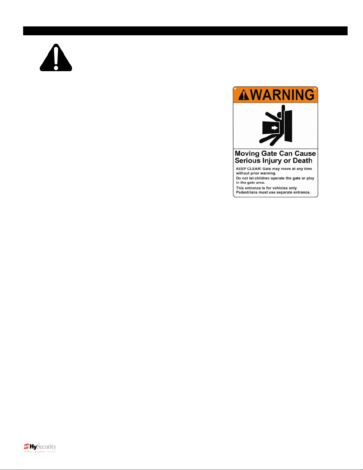
The entry is configured for vehicular use only. Pedestrians must be directed
to a separate walk-through entrance. The Warning signs that have been
supplied with this operator must be installed in a manner clearly visible on
both sides of the gate.
All openings of a horizontal slide gate are guarded or screened, from the
bottom of the gate to a minimum of 4 feet (1.2 m) height above the ground, to
prevent a sphere 2 ¼ inches (57 mm) in diameter from passing through an
opening anywhere in the gate or the portion of the adjacent fence that is
covered in the open position.
All exposed pinch points, rollers and wheels are guarded. To reduce the risk
of entrapment, the gate must also be installed so that enough clearance is
provided between the gate and adjacent structures both when opening and
closing. Minimize the parallel gap between the gate and the fence.
The gate has been constructed with physical stops to prevent over-travel in
both directions and has guard posts that prevent the gate from falling in the
event of a roller failure.
Review and meet all ASTM F-2200 and UL 325 automated gate system
standards.
Possible
Pinch Point
3 D0119, Rev. F
Page 12
Installation and Maintenance Manual
p
p,
g
A
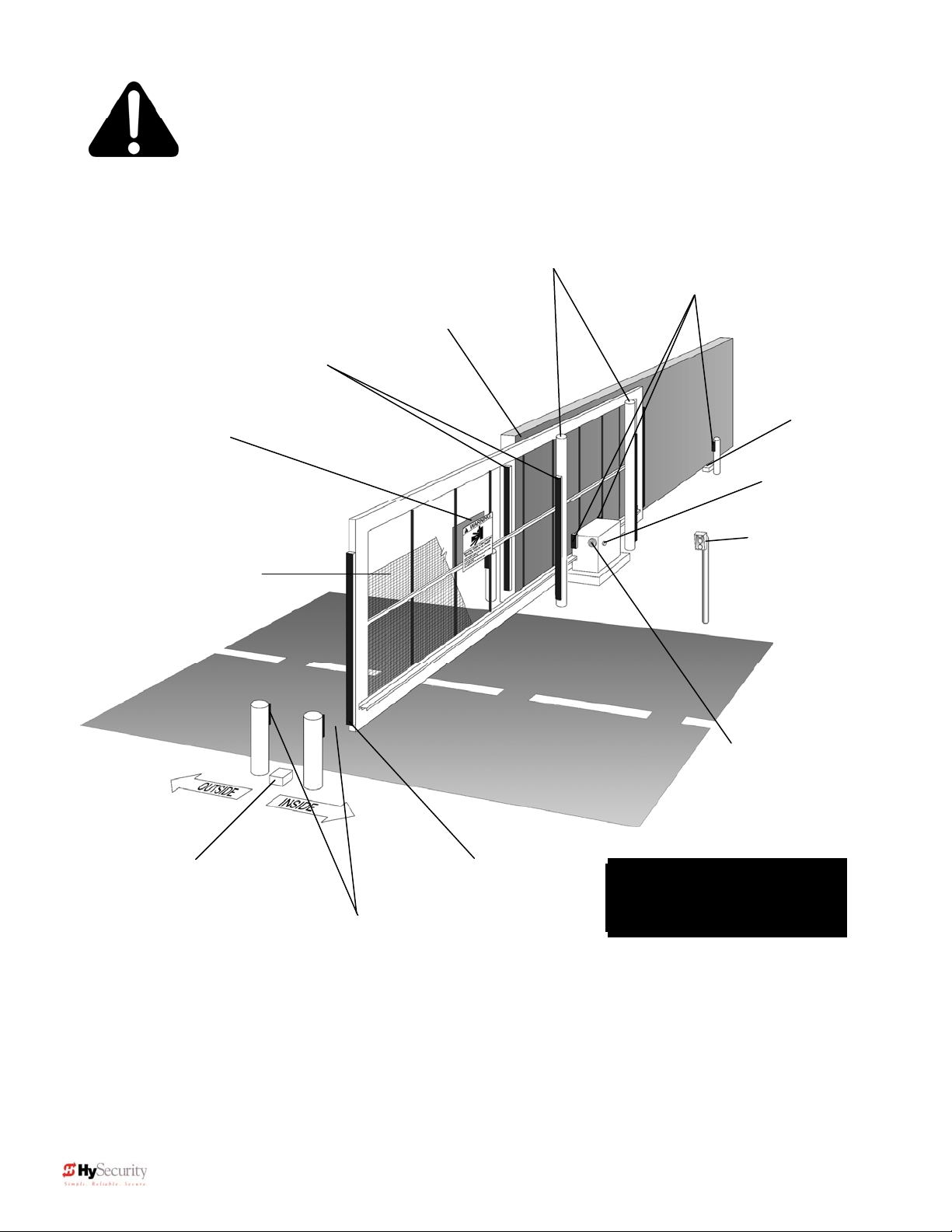
Sliding Gate
Warning signs must
be on both sides
2” safety mesh
prevents reachthrough: height not
less than 48 inches
Entrapment Protection
Guard posts
Photo Eyes for
both directions
Keep this gap as
small as
Gate edge
sensors
ossible
Physical travel
stop, both ends
Stop and reset
button
Access controls
at least six feet
away from gate
and operator
udio alarm
Physical travel
both ends
sto
Photo Eyes for
both directions
each side of
ate
Gate edge sensor,
on leading edge
and trailing edge
Note: All wheels must be
covered. (Wheels and
covers not shown for clarity)
This schematic view is not meant to recommend the only way to set up your configuration, but
to point out the various elements of a proper automatic vehicular gate installation. The gate
operator itself is only one component in the total system. Always install a separate
pedestrian gate.
4 D0119, Rev. F
Page 13

Installation and Maintenance Manual
Site, Gate, Equipment and Regulatory Requirements
The gate moves freely in both directions. Never over-tighten a clutch or pressure relief valve to
compensate for a stiff gate.
The operator will be installed on the secured (non-public) side of the gate.
The operator will be properly electrically grounded and the intended supply voltage matches the
voltage label on the operator.
The controls that operate the gate have been mounted far enough away from the moving gate
such that users cannot touch the gate while operating the controls. All easily accessible controls
must have a security feature to prevent unauthorized use.
The operator controls will be located in a clear line-of-sight to the gate. Radio controls and other
remote access controls must be connected only to the Remote Open input.
The required external entrapment sensors will be installed. Be certain to carefully review the
instructions for placement, installation and adjustment of these external entrapment sensors.
External entrapment sensors must function to reverse the movement of the gate in both the
opening and closing directions. If edge (contact) sensors are used, they are to be mounted on
the leading and trailing edges of the gate, as well as post mounted on the inside and outside of the
gate (See figure on page 4). If photo eyes or other non-contact sensors are used, they are to be
mounted in locations most likely to guard against entrapment. A combination of contact and noncontact sensors may be used, but all must be recognized components under the UL 325 standard.
See pages 31 and 32 for details on the requirements.
If the Entrapment protection is provided by a continuous pressure actuation control, a placard
stating “WARNING” – “Moving Gate has the Potential of Inflicting Injury or Death - Do Not Start
Gate Unless Path is Clear” must be posted. Additionally, no other activation device shall be
connected and an automatic closing device of any kind shall not be used.
The automatic operator is labeled as appropriate for both the type and UL usage class of the gate.
Note: Sliding gate operators installed in Class I & II applications must not move the gate faster
than one foot per second.
Class I: Intended to serve single to four family residential uses
Class II: Multi-family use, or any application intended to serve the general public
Class III: Commercial applications not intended to serve the general public
Class IV: Highest security. Security personnel prevent unauthorized access
Sliding gate operators installed in Class III & IV applications do not have a speed restriction and
the secondary entrapment sensor requirement is met if the system is configured as described for
Class I & II use, or by the following alternate means: Employ the use of a 100dB buzzer, which
sounds at least 3 seconds before the gate moves, and/or functions only by use of a constant
hold type push button control.
5 D0119, Rev. F
Page 14
Installation and Maintenance Manual
Important Information for Gate System Owners & Users
WARNING: To reduce the risk of serious injury or death, read and follow all
instructions in the gate operator handbook and on the warning labels.
Save These Important Owner and User Instructions:
(Installers – be certain to instruct the owners and users about the
following items)
Automatic gates are for vehicular use only! Provide walkways and
signs to direct pedestrians to a separate walk-through entrance.
Because an automatic gate can start at any time without warning,
always keep people away from the area of the gate. The Warning
signs that have been supplied with this operator must remain
installed, in manner clearly visible on both sides of the gate.
Never allow children to use or play with controls that operate the
gate. Keep all remote controls, especially radio transmitters,
away from children.
Teach all users how to turn off the electric power and how to
release and move the gate manually. Use the manual release
only when the gate is not moving.
Test the function of the gate operator monthly. The gate MUST reverse its direction of travel
upon contact with a rigid object, and/or stop upon a sensing a 2
reaching a full travel limit. Also test for the normal function of any non-contact sensors. If the
gate system employs the use of a transmitting edge sensor, be especially certain to test and
replace its battery on a routine basis.
KEEP AUTOMATIC GATES PROPERLY MAINTAINED. Have a professional gate installer
perform routine tests of the entrapment protection sensors, such as photo eyes and gate edges.
Also, make all necessary repairs to the gate hardware to keep the gate running smoothly.
Failure to adjust and test a gate operator properly can increase the risk of injury or death.
In addition to appropriately placed external entrapment sensors, ask your installer to reduce the
setting of the pressure relief valve to the lowest setting allowable that reliably operates the gate.
This valve controls the force of the operator, and the sensitivity of the inherent reversing sensor.
Do not physically disable the Warning Buzzer and never disconnect or cut its wires. The
buzzer is required to function in event of entrapment, regardless of UL 325 classification. If
modification of the buzzer function is required, the operational modes for the buzzer (warn before
operate, etc.) can be selected within the Smart Touch menu settings.
nd
sequential activation prior to
6 D0119, Rev. F
Page 15
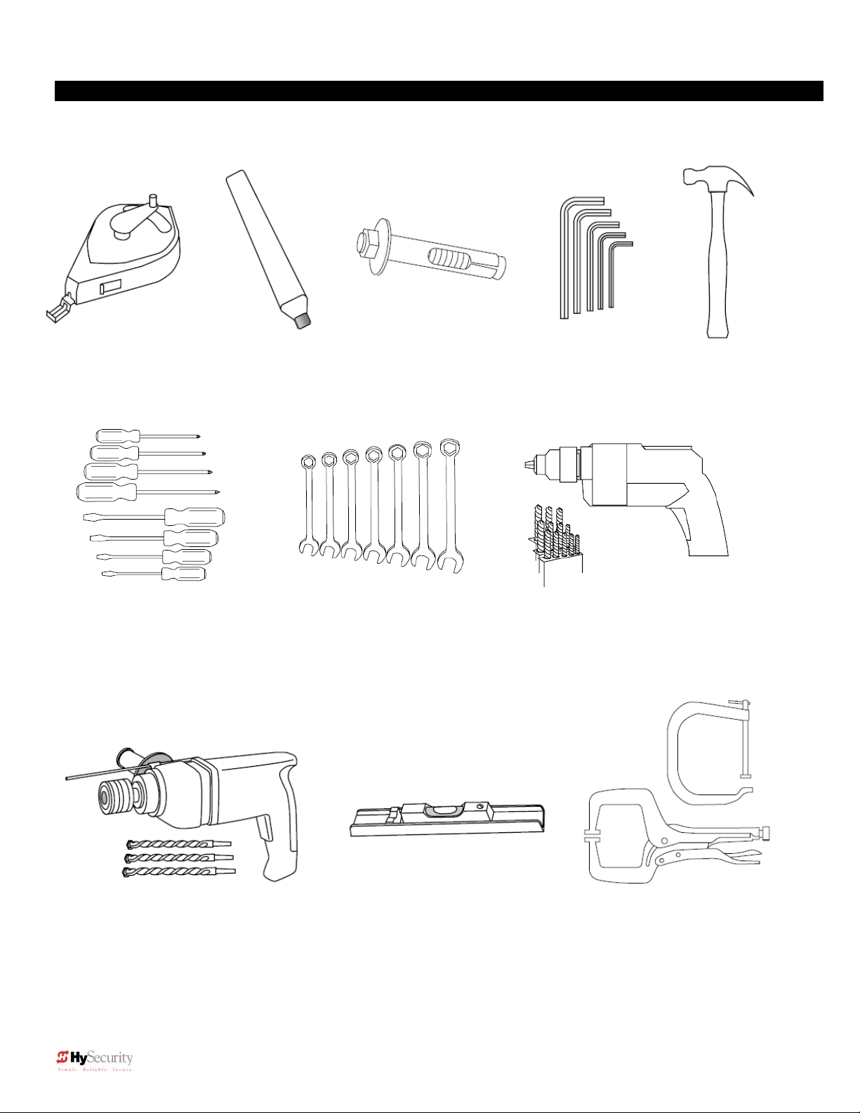
1. Chalkline or other
builders string
2. Carpenters
pencil or crayon
Required Tools
3. Concrete anchor
bolts, four 1/2" x 4"
Installation and Maintenance Manual
4. Allen wrench set
5. Hammer
6. Screwdriver sets,
Straight and Phillips
7. Wrench set, open
end, 1/4" through 1"
8. Electric drill and bits,
1/8" through 3/8"
9. Roto-hammer and bits 10. Level (installation must be level) 11. Two pair wide
Jaw pliers or two
C clamps, 4” cap.
7 D0119, Rev. F
Page 16
Installation and Maintenance Manual
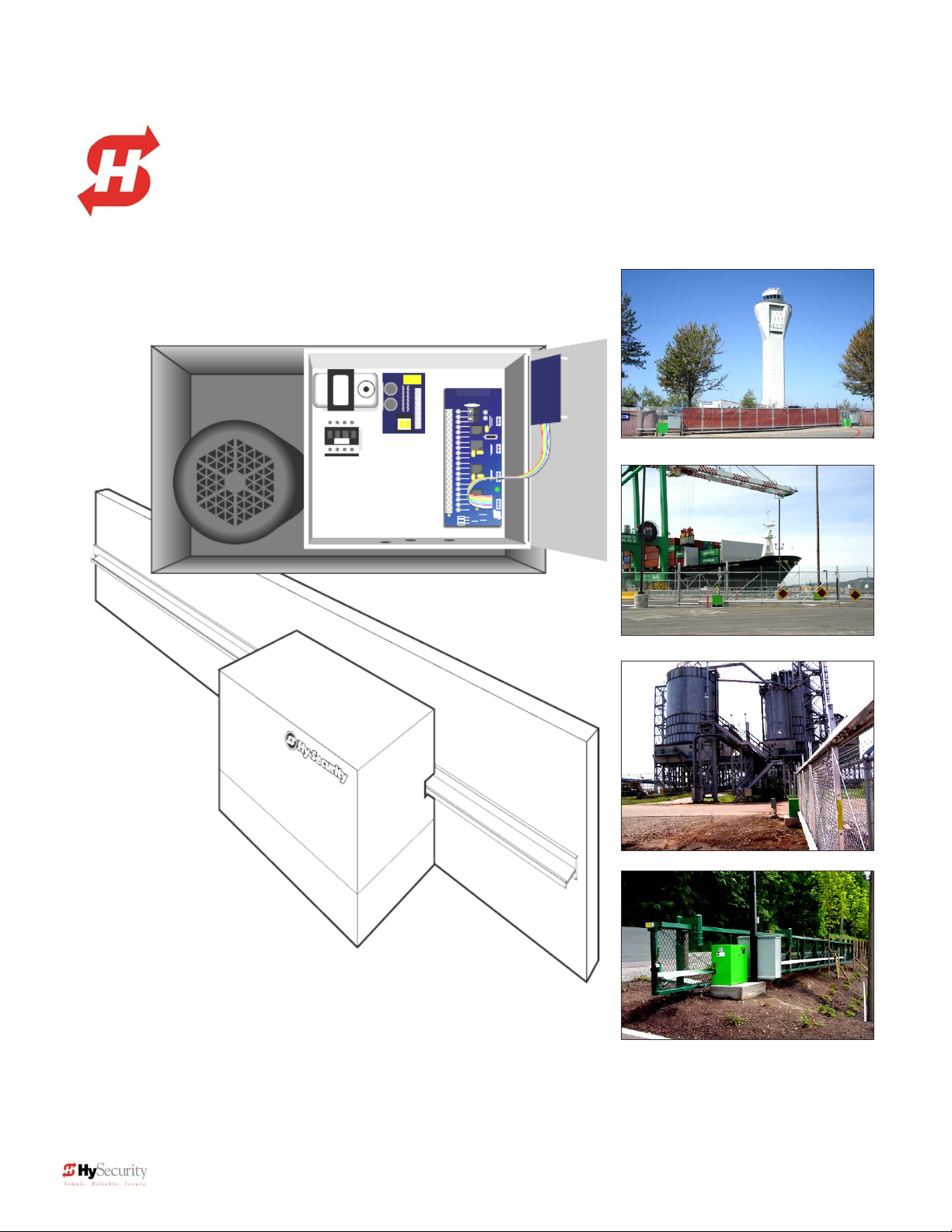
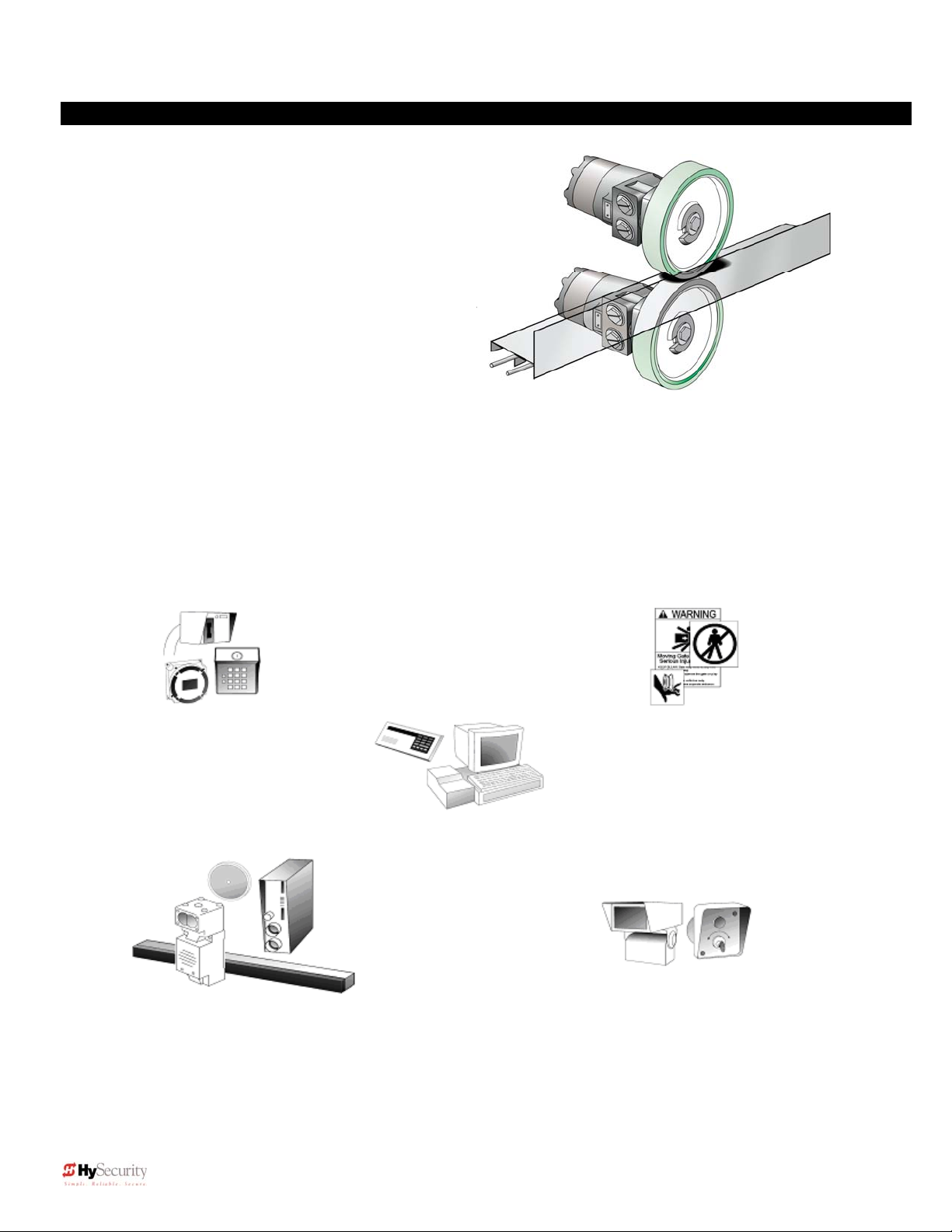
Getting Started
• How this hydraulic operator works
HySecurity industrial slide gate operators rotate polyurethane
treaded drive wheels which grip a rigid metal drive rail and feed it
right or left during the gate travel. The drive wheels are clamped
above and below the drive rail and are directly coupled to
powerful hydraulic motors, which can easily move large gates.
This simple yet durable drive system is one of the unique
features giving our hydraulic operators their reputation for
reliability.
• Accessory Compatibility
HySecurity’s Hydraulic Slide Operators are fully compatible with all standard access control devices and
entrapment protection devices, some of which are listed below.
• Pedestrian Entrapment Protection
Read and understand all the Important Information in Section 1, the Entrapment Protection Schematic on page
4 and the UL requirements on page 3 before beginning the installation. Be absolutely certain that the required
type and quantity of Entrapment Protection devices have been supplied and that you understand how to install
them correctly. Contact your local distributor with questions about Entrapment Protection.
Basic Access Control
Radio Transmitter
Long Distance Control
Pushbutton Control Station
Programmable Time Clock
Card Reader
Obstruction Sensing Devices
Inherent Sensing Device
Gate Edges
Photo Eyes
Vehicle Detectors
Information
Signs
Labels
Warnings
Advanced Access Control
Access Control Interface
Card Reader
Keypad
Telephone Entry
Input/Output
Computer Interface
RS232/485
Security
Key Locks
Closed Circuit Television
Gate Position Indicator
Interlock/Sally Port
Gate Status Indicator
8 D0119, Rev. F
Page 17
Installation and Maintenance Manual
f
Installation Preparation Checklist
1. Read all of the instructions, especially the
Important Information in Section 1 at the
beginning of this manual, before you attempt
installation. This section is focused upon
mechanical installation. For electrical setup,
refer to Section 3, on system configuration
and use of the Smart Touch Controller.
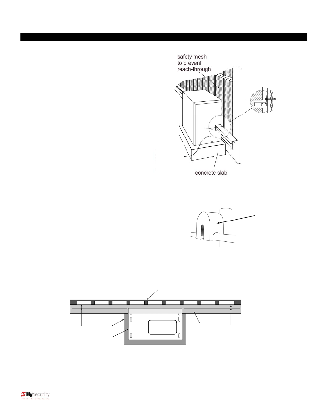
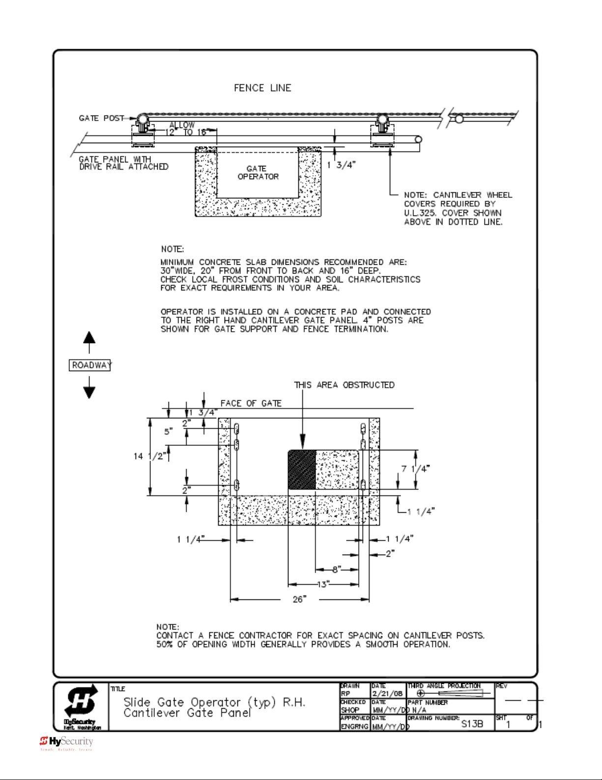
2. Check to see that the mounting slab is the
recommended size and ready to have an
operator attached. Also check that electrical
conduits are correctly located to enter the
chassis. HySecurity recommends a slab
reaches below the local frost line and
extends somewhat above grade. See the
footprint plan and elevation view on pages
14 and 15.
3. Make sure the gate rolls smoothly in both
Drive rail
location
9 ¼” from top
of slab to top
o
drive rail
directions, without any binding of the gate
hardware. If the gate is warped or hard to move, stop and fix the gate before attempting to automate.
4. Verify that you have covers for all exposed gate support
Figure B
wheels. These must be installed. Also, look around to
identify all of the potential pinch points and hazardous areas,
and plan the best location for the entrapment protection
devices and warning signs. Remember that you are required
to advise the owner regarding the potential hazards of an
automatic gate and about the function of the entrapment
protection sensors that you have selected and installed.
5. There are 3 steps to a perfect install: location, location, location. One of the most critical adjustments in
installation will be to make sure the operator is located the proper distance from the gate, and that the gate
and operator are as parallel as possible. See Figure C below. Prepare some shims for aligning the drive rail.
gate
1 ¾”
slab
operator
drive rail
Note: If necessary, shim the drive rail so that it is straight ± ¼” throughout the travel
distance of the gate.
Figure A
1 ¾”
Gate face to back
of operator
Remember to
cover all four of
the cantilever
gate wheels
Figure C
1 ¾ “
9 D0119, Rev. F
Page 18
Installation and Maintenance Manual
Installation
1. Drill four holes for concrete anchors
A paper template can be made by setting the operator on a large sheet of paper and
tracing the outside edges and anchor slots. Place the template or operator on the
slab; making sure that it is parallel to and 1 3/4" from the gate face. Trace the slots,
remove the template, and then scribe the locations for your anchor bolts. Drill holes
for the anchor bolts in the center of at least 2 slots per side so that you will have
some room for adjustment. Install at least four ½" x 6" concrete anchor bolts, using
at least two per side.
2. Line up the operator
Put the operator in position onto the anchor bolts. Verify that the operator is
parallel and 1 3/4" away from the gate. Tighten the anchors securely.
Two part Operators (DC models and 333 modular models)
3.
These two part operators come with a separate enclosure, which
should be mounted between 10 and 100 feet of the operator. We
recommend wall mounting or using two 4” posts, with horizontal
mounting strut to create a support for this enclosure.
Roll pins
line up
drive rail
segments
to assure
perfect
splicing
4. Bolt the Drive Rail to the Gate Panel
Connect multiple sections of drive rail together with ¼” roll pins for a perfect splice. The drive rail must be bolted to
each vertical member of the gate panel. This may be done with U-bolt clamps or through bolts, however U-bolt clamps
allow for easy up down adjustment. If the gate is bent or warped, shim the drive rail so that it is straight +
throughout the travel of the gate. When the drive rail has been installed at the correct height, the top surface is 9 ¼”
above the operator base. A label and notch on each side of the operator indicates the correct height.
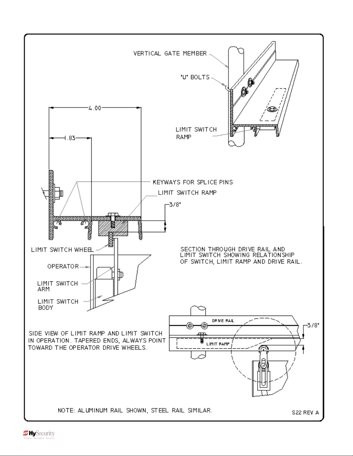
5. Install Limit Ramps on Underside of Drive Rail
Push the gate to the fully closed position and drill two 3/8” holes
through the drive rail to mount a 12” plastic limit ramp under the
drive rail, in the wheel channel. Locate drive rail so that it will trip the
limit switch approx. 6” before the exact spot you want the gate to
stop. Adjust the ramp left or right to achieve exact stopping point.
Fully secure by tightening both bolts. Adjust the lever arms on the
limit switch so that the roller clears the underside of the drive rail by
at least 1/4 inch. Push the gate fully open and repeat this
procedure with the other limit ramp. See the Drive Rail drawing
S22 on page 16.
vertical gate post
shim as necessary
Drive rail
Limit ramp
Limit Roller
Limit switch
slab
¼”
10 D0119, Rev. F
Page 19
Installation and Maintenance Manual
Installation
6. Clamp the Drive Wheels to the Drive Rail
When the wheels are fully clamped on the drive rail, the red
spring should be compressed to 2” in height. If adjustment
is necessary, turn the nut at the bottom of the threaded rod
assembly. Slightly less compression is okay for lighter
gates. See Use of Manual Release on page 54
7. Electrical Power Connection
This operator is intended for permanent installation, so all
electrical conduits must be properly connected to the control
box. The entry for the primary power is a ½ - ¾” knockout
on the left side of our control box next to the on-off switch.
When this operator was manufactured, it was built to run on
a specific voltage and phase for line power. Make sure you
have compared the line voltage and phase available with the
nameplate on this machine. They must match! Be certain
that the wire size of the branch circuit that will supply the
operator vs. the distance of the run from the main panel is
large enough to avoid excess voltage drop. At a minimum, a
20 amp circuit (protected with a 20 Amp Inverse Time
Breaker) should be provided. Also be sure the operator is
electrically well grounded per NEC Article 250 and local
codes. See pages 61 and 62 for correct wire sizes and
detailed electrical wiring information.
8. Primary Tap of Control Transformer
(not on battery operators)
Check to make sure that the primary tap on the control
transformer matches the line voltage you have connected to
the operator. Measure the line voltage carefully to
distinguish between 208V and 230V branch circuits. A label
on top of the transformer identifies the various voltage taps.
9. Electrical Power for Two Part 333 type operators
The primary AC power must be routed to the controller
enclosure with the pump, but there must also be conduits between
the gate operator and the controller enclosure.
Note: AC power is not needed in the gate operator, unless there is an optional heater. A minimum of two
separate conduits must be provided, 2” for the hydraulic hoses and ¾” for the electrical interconnections.
Unless there are accessories in the gate operator, the only electrical interconnection between the two
enclosures will be three wires between the two terminal strips for the limit switches. Join the hydraulic
hoses by plugging the quick coupling together according to the hand of the gate. See the on page 59.
11 D0119, Rev. F
Page 20
Installation and Maintenance Manual
)
Installation
10. Connections for Two Part Battery Operators
The primary AC power must be routed to the DC power supply enclosure, but there must also be at least one 2”
conduit between the gate operator and the DC supply enclosure. Note: AC power is not needed in the gate
operator enclosure, unless there is an optional heater. Three separate DC circuits are required between the
battery supply and the gate operator. Heavy gauge wires to supply the motor and two 14-gauge circuits for the
controls. The heavy gauge wire must be at least 6-gauge if the DC supply is within 20 feet of the operator, but
must be increased to 2-gauge if the DC supply is located farther from the operator or this is a SlideDriver 30F
(222 EX 1.7) – 1.7ft/sec model. Also see page 56 titled “Wiring and Control Configuration for DC Operators"
and Drawing E125 on page 58.
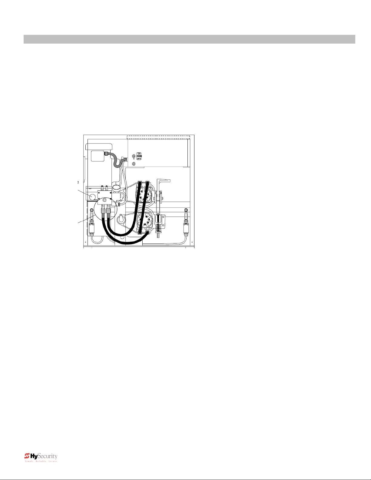
11. Check the operator “Hand” All slide
operators must have their “hand” set before they
Remove the 1/2”
steel or red plastic
shipping plug and
replace with black
breather cap
To change hand
connect hoses
according to label
(“Right Hand”
on tank
shown
12. Replace the Shipping Plug!
Replace the ½” steel or red plastic shipping plug on the front side of the pump with the black breather cap.
Failure to do so may contribute to premature shaft seal failure.
13. Setup Smart Touch Controller
The operator controls will not allow the gate to function until the Smart Touch Controller has been configured.
Wait to connect external controls until you have reviewed Smart Touch Controller instructions and tested
operator basic functions.
Note: HySecurity has an installation CD available free of charge. Call a HySecurity distributor for your copy.
can function. The “handing” must be set both by
the proper hydraulic hose connection and
electrically. The hose connection for proper
handing is described on a label near the hose
connection point. Also, see the instructions to set
handing on page 18 “Installation Configuration for
Smart Touch Controller.” Handing is viewed by
standing in the middle of the road on the secure
side looking out. A gate which opens to the right is
a right handed gate. A gate which opens to the left
is a left handed gate.
12 D0119, Rev. F
Page 21
Installation and Maintenance Manual
Mechanical and Hydraulic Adjustments
1. Drive Wheel Spring Tension
When the drive wheels are fully clamped on the rail, the red spring should be compressed to 2” in height. Turn
the nut at the bottom of the threaded rod assembly to adjust. Slightly less compression is okay for lighter gates.
(See Figure on page 11)
2. Drive Rail
With wheels unclamped and manually moving the gate, verify that the drive rail does not vary more than 1” up
and down, or ¼” in and out throughout the entire horizontal travel of the gate. Re-alignment is simple if the rail is
mounted with U bolts. To adjust in and out, loosen the U bolts and add or remove shim stock. To adjust up or
down, loosen the U bolts and simply tap the rail with a hammer until the correct height is reached. Adjusting the
rail in or out requires inserting shims between the rail and the gate where necessary.
3. Brake Valves SlideDriver 40 & 30F (222 E & EX 1.7) models only
If your operator is equipped with brake valves, their proper adjustment
is important for smooth operation of the gate. In order for the brake
valves to have time to function, the limit ramp must trigger the limit
switch at least six inches before the point at when you want the gate to
stop. Adjustment of the brake valves, one for each direction of travel,
will determine how quickly the gate actually stops. If adjustment is
needed, loosen the 9/16” lock nut on the top of the brake valve and turn
the adjustment stem, in about ¼ turn increments, with an Allen wrench.
The adjustment works opposite of typical, a counter-clockwise
adjustment will stop the gate more rapidly. If the adjustment is set too
loose, the limit ramps will bang into the drive wheels. If the adjustment
is set too tight, the system pressure will increase, the gate speed may
decrease and the gate will jerk to a stop. Set the brake valves to
achieve a controlled smooth stop, with the limit ramp 1.5” to 3” from the
wheels, then retighten the locking nut to hold the setting.
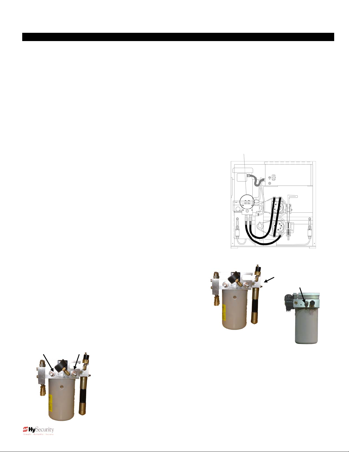
4. Pressure Relief Valve
The operating pressure limit is factory preset to a level that will
operate most gates well. A gate may require pressure relief
valve adjustment on install. To provide maximum entrapment
protection, do not set the pressure limit higher than necessary
for good operation (see procedure and maximum settings on
page 52). This valve, which governs the maximum system
hydraulic pressure, is located on the backside of the pump,
above the AWOG on SlideDriver 40 and on the same manifold
but facing the operator chassis on other operator models.
Reduce the relief valve setting to the lowest pressure that will
reliably operate the gate. A lower
Open Valve Unloader
Valve
setting reduces the operator’s
maximum force.
5. Open and Unloader Valves
These two valves are solenoid operated. The Open valve is below the motor near
the front of the pump and energizes in order to direct the hydraulic flow to open the
gate. The Unloader valve, which is near the back of the pump energizes at the
beginning of a cycle to allow no load motor starts and at the end of each cycle to
aid in decelerating the gate. No adjustment of these valves is possible or
necessary. Valves are wrapped with black plastic valve coils.
Optional brake valves CCW = quicker stop
Left valve controls open
Right valve controls close
“Right Hand” Hose connections shown
Pressure Relief Valve
Left: SlideDriver 40, 80, 200
Behind black switch
Right: All other models
13 D0119, Rev. F
Page 22
Installation and Maintenance Manual
14 D0119, Rev. F
Page 23
Installation and Maintenance Manual
15 D0119, Rev. F
Page 24
Installation and Maintenance Manual
16 D0119, Rev. F
Page 25
Installation and Maintenance Manual
Smart Touch Basics
Read this page if you are unfamiliar with using the Smart Touch Controller.
You must learn to navigate and change menu settings with the Smart Touch Controller before an installation
can be completed or any control settings or function changes can be made.
Until a new operator has been configured, the controls are not functional and the display is locked in
the menu mode until the User Class 1-4, and Left or Right hand use have been selected. See the next
page for instructions on how make these settings.
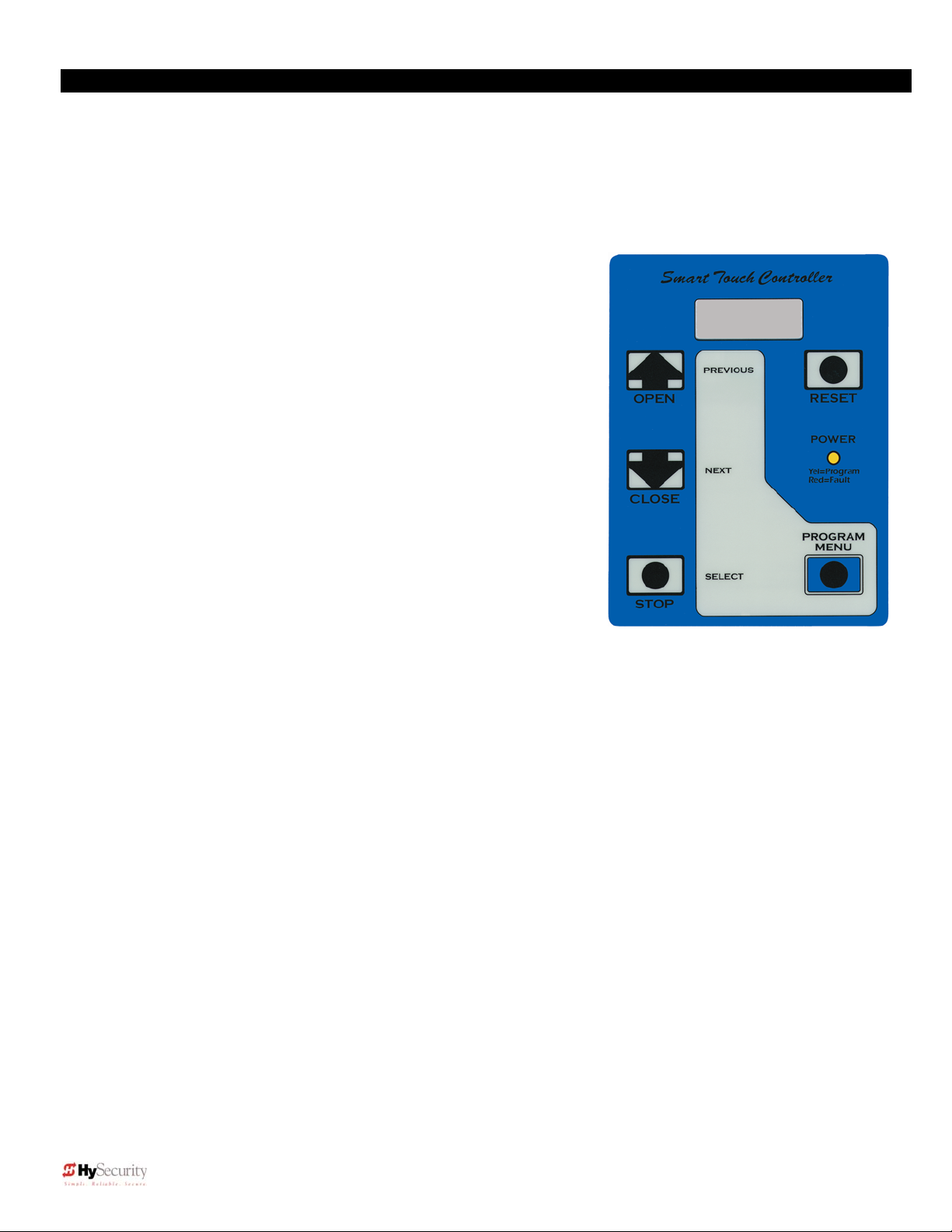
1. There are five buttons on the membrane switch pad that
provide total operator control. The Open, Close and Stop
buttons serve as a three-button control station, but in Menu
Mode, they become Previous, Next and Select buttons. The
Program Menu button is used to both enter and exit Menu
Mode. The Reset button clears all Errors and Faults and
returns the operator to its normal functioning state.
2. When in a Menu Mode, changes to be made to a Menu setting
are accomplished by pressing the Previous, Next and Select
buttons in the following sequence:
a. Press the Next button to move forward through the list
of available menu items, as shown on pages 22 and
23, or press the Previous button to move back an item.
b. Press the Select button to select a menu item to
change. The menu item will flash to indicate that its
setting is ready to be changed.
c.
Press Next to move forward or Previous to go back through available settings.
d.
When you have located the new setting that you want to use, press the Select button and the
program accepts the change and stops blinking.
e.
The Program Menu button does not allow an Exit to Run while a selection is still blinking. Press
the Select button to confirm the new setting and stop the blinking. Then exit to Run Mode.
f.
Pressing the Next or Previous buttons when the menu item is not blinking moves to the next or
previous menu item.
g. When done, press Program Menu to exit to Run Mode.
3. Once configured, the operator is in the Run Mode. To gain access to the User Menu or the Installer
Menu from the Run mode, follow these steps:
a. Press the Program Menu button and watch the LCD scroll the system data, or press the Program
Menu key a 2
page 22.
Note: The Program Menu button will not function unless the gate is at rest, open and close
inputs are not active, and the operator is not displaying a Fault, Alert or Error. Verify system
status by viewing lighted (active) inputs. Active inputs are lighted on this and all “New
Generation” (post September 2006) Smart Touch operators (other than DC operators without
AC power). Verify active inputs on “New Generation” DC operators (running without AC power)
and “Classic” pre-September 2006 operators, by pressing the tact button located in the lower,
nd
time to skip the scroll. The scrolled data displays the information in the table on
17 D0119, Rev. F
Page 26

Installation and Maintenance Manual
left area of the Smart Touch Controller (see page 20). If necessary, clear Alerts, Faults or
Errors by pressing the Reset button on the Smart Touch Controller membrane switch.
b. The LCD display scroll will stop at the menu item for the automatic close timer setting [Ct __].
This is the first item in the User Menu.
c. To access the more detailed Installer Menu, first go to the User Menu. Then press and hold the
Reset button and while holding, press the Open button. The LCD will change to display the UL
usage class menu item [uC __] This is the first item in the Installer Menu.
4. Pressing the Program Menu button when the User or Installer Menu is not blinking will return the system
to the Run Mode.
Installation Configuration for Smart Touch Controller
Setting Operator Handing and Usage Class
1. Connect the hydraulic hoses to the quick couplers on the pump in order to configure left or right hand
opening function (as viewed from the secured side of the gate). There is a label near the connection
point describing this procedure. Also see the illustration on page 12. If the hoses are connected
incorrectly, the gate will run backwards (close when open button is activated) and this may trigger an
error [Err 1] on the LCD display. If an error occurs, reverse the hoses to the correct position and press
the Reset button to clear the error.
2. Turn on the power switch and observe that the LCD will first show the software version, and then stop at
a steady display within two seconds. If the display reads [uC 0] go to step 3. If the operator has
previously been configured, the Installer Menu must be accessed in order to reach the system
configuration menu items: See step #3d at the top of this page.
3. When turning on the power for a new machine, the LCD display directly enters the Installer Menu at the
[uC __] menu item, which is for selecting the user class as defined by UL. Select [uC 1] - [uC 2] - [uC
3] or [uC 4] depending upon the use application. See page 31 for UL usage class definitions.
4. To set the operator handing, use the “Next” button and move one click down the menu to item [Sh __]
Enter r for right hand or L for a gate that opens to the left. Never alter the limit switch mounting or
change the order of their connection to the controller board. At this point you should exit the Installer
Menu, by pressing the Program Menu button. The LCD display jumps to the close timer [Ct__] setting in
the User menu, which may now be set. Either press the Program Menu button again to exit to normal
run mode or set the close timer by the same programming sequence described at the previous page.
5. Note that the Installer menu cannot be exited by any means until the selection for UL usage class
[uC __] and the selection for gate handing [Sh __] have been entered.
6. Test for normal function of the gate operator, with the wheels unclamped, by running it both open and
closed from the pushbuttons on the membrane switch pad. Neither limit switch should be triggered at
the start of this test or an alert [ALE6] may trigger because the control did not sense gate motion. If this
occurs a new input will restart the motor.
18 D0119, Rev. F
Page 27

Installation and Maintenance Manual
Wiring Control Inputs
1. Test open and close before wiring the external control inputs. This makes it easier to troubleshoot if an
unexpected functionality arises. “New Generation” Smart Touch Operator inputs (after Sept. 2006) use
an LED to indicate when it is active. DC operators operating without AC require you to push and hold an
LED button to disclose input status. This button is in bottom corner near the Fire Department Open
input. [“Classic,” pre-Sept. 2006 operators LEDs are only lit when you push the Tact button. The Tact
button is located on the top left corner, near the Stop Button input on the Classic Board.]
2. All the control device inputs listed below are shown as a single input. The 2nd wire is connected to the
Common Terminal Buss on the Power Supply board. The Emergency Close and Fire Dept. Open inputs
are an exception and require a +24 Volt input. The +24 is located on the spade terminals next to the
Common Buss. See pictures on the next page.
Smart Touch Controller Inputs
1.
2.
3.
4.
*Stop Push button N.C. input, jumper to Common if unused
*Open Push Button Not for radio or remote access controls
*Close Push button Not for radio or remote access controls
Remote Open & Radio Control For radio / remote open device –
Program to also Close using Smart Touch menu
5.
6.
7.
8. Free Exit vehicle detector
9. Disable Free Exit vehicle detector or Timer to Close
10.
11.
12.
13.
14-15. Photo eye Common Power
17. Photo eye Open direction
19. Photo eye Close direction
21.
22.
23.
24.
Open/Close button Pushbutton or radio controls
Partial Open Installer adjustable from 7- 99 seconds
Open interlock input or Time clock Open Menu configurable
Free Exit is only disabled if Close Limit Switch is tripped. If the gate is
partially opened, the Free Exit detector will trigger the gate to open fully.
Inside Obstruction vehicle detector Inside reversing loop
Outside Obstruction vehicle detector Outside reversing loop
Shadow/Reset vehicle detector Shadow function used for Swing
gates only - Reset function is for Arm gates
Edge Sensor One input works for both travel directions
24V common connection for open and close photo eyes
Charger AC power loss Only used in DC, battery type operators
Spare Input Software ≤ h3.24,- non functional,
Gate Lock Interlock Input Software > h3.24, prevents start until
external gate lock releases
**Emergency Close Must menu enable and input +24 Volts to trigger.
Requires constant hold or maintained input. This overrides photo eyes,
gate edges & vehicle detectors.
**Fire Dept. Open Must menu enable and input +24 Volts to trigger.
Overrides photo eyes & gate edge.
*
Do not connect an external control to terminals #1, 2 or 3, unless controls are
located in clear view of the entire gate area. Out of sight controls: use input
terminals #4, 5, 6 or 7.
**The Emergency Close and Fire Dept. Open inputs are to be used only if access
to these controls is guarded such that there is always supervision when activated.
19 D0119, Rev. F
Page 28

Installation and Maintenance Manual
“New Generation” Smart Touch Board
Connector to
Runs software
SlideWinder Drive Board
4.xx and higher
1. Stop Button
2. Open Button
3. Close Button
4. Remote Open & Radio Control
5. Open / Close
6. Open Partial
7. Interlock Open / Time Clock Open
8. Free Exit Detector
9. Disable Exit Detector / Disable Close Timer
10. Inside Obstruction Vehicle Detector
11. Outside Obstruction Vehicle Detector
12. Shadow / Reset Vehicle Detector
13. Edge Sensor
14. Photo Eye Power (-) 24 Volts Common
15. Photo Eye Power (-) 24 Volts Common
16. DO NOT USE
17. Photo Eye Open Direction
18. DO NOT USE
19. Photo Eye Close Direction
20. DO NOT USE
21. Charger AC Loss
22. Gate Lock Interlock
23. Emergency Close
24. Fire Department Open
Tact button. Push tact button to make active
input LEDs light up when AC is off on DC
INPUTS
operators.
Power Supply Board
LEDs showing active input circuits
now always enabled except for DC machines (during AC loss)
Power Connector
UNUSED
MX000585
RS 485 Future Expansion (new)
Motor Relay
Reset & Buzzer
Connector
User Relay 1
User Relay 2
User Relay 3
DC only
Solid State for use
with fl ashers and
other high cycle
accessories.
48V DC @ 4 amps.
Clock Battery
Heartbeat
LED
Socket for
Ribbon Cable
to Display
RS 232 socket
Weigand
Future Expansion
4 - HY-5A
Vehicle
Detector
Sockets
24V DC Accessory
Power (+)
Limit Switch
Connectors
Master
Slave
Open
Radio
Gate Edge
Radio
HY-5A Vehicle Detector
Common Buss (-)
24V AC Accessory power
20 D0119, Rev. F
Page 29

Installation and Maintenance Manual
Connecting a Master / Slave Pair
Configuring two operators to be a Master & Slave pair is easy with the Smart Touch Controller. There is no
need to order a special model or any adapters. The area of the board marked Dual Gate employs a 3-wire
RS485 serial port for communication between Master & Slave operators. Note: Master Slave operators must
have the same version of software loaded on both machines.
1. An electrical conduit for the interconnecting wires must span between the two operators. This conduit
must contain only low voltage ≤ 24V control and signal wiring.
2. Complete the installation of both of the operators as separate machines and verify that their basic
functions are correct as solo operators before interconnecting them.
3. The two gate operators should be supplied by home runs from separate 20 Ampere circuit breakers in
the main panel, but if there is only one circuit, be absolutely certain that the breaker and wire size is
sufficient for the load of two motors. See the Appendix.
4. External control inputs, vehicle detectors and entrapment protection sensors may be connected to either
gate operator without regard to preference.
5. To interconnect the two operators, route a shielded twisted triple cable between the electric control
boxes and connect to the RS485 Dual Gate terminals, in matching order on both machines: In the
RS485 shaded area connect the terminals for Master Com to Slave Com, Master A to Slave A and the
Master B to Slave B using the insulated trio of wires. Connect the shield to a solid ground at either the
Master or the Slave unit (Do not ground both ends). Cut off the shield and insulate (tape up) the
exposed strands at the other operator.
6. The Installer Menu in each machine must be set as a Master or a Slave under menu item [dg__]. Set
one operator as a Slave [dg_1] and the other as a Master [dg_2]. If the function of any external input is
to be different than the factory default, configure for the desired function on the operator where that input
is connected. Internal functions, such as the close timer or reversal distance, are controlled by the
Master operator regardless of the settings in the Slave.
7. Once set as a Master or a Slave the operators will be in constant communication with each other. If that
communication stops because the wires become severed or one operator is turned off, both machines
will cease functioning and the LCD will display Err4, which is a Master/Slave communication error. This
error cannot be reset until both machines are functional and communicating properly again.
21 D0119, Rev. F
Page 30

Installation and Maintenance Manual
Smart Touch User Menu Functions
Initial Power Up – When power is turned on, the display will disclose the software revision:
h4.23 2s delay Displays software version Number
Software version 4.23 provides the options, adjustments, display code and functionality described in the
remainder of this manual. Older versions may differ slightly. Free Software Upgrades using HySecurity’s
START software are available online at www.hysecurity.com
System Data and accessing the User Menu Settings:
If the gate is stopped in the Run Mode, pressing of the Menu button accesses the User Menu. After the menu
button is pressed, the LCD will scroll the system data in the table below. The scrolling display stops at the close
timer setting, which is the beginning of the User Menu. To exit the Menu Mode, the display must not be blinking,
then simply pressing the Menu button will return the display to the Run Mode and re-enable the controls. The
menu mode will also automatically return to the Run Mode if there is no activity for two minutes.
Data Displayed in Scroll Time Description
S1
[SLAu] or [LEAd]
S2
[ot 1] Gate type (1-5) 2s Operator type: 1 =HSG, 2 =HRG, 3 HVG, 4 =HTG
S3
[_rh_] or [_Lh_] Hand setting 2s Displays hand configuration [_rh_] or [_Lh_]
S4
[uC _] UL usage class (1-4) 2s Installer setting of usage class: type 1-4
S5
[d___] 24VDC Buss Voltage 2s Actual VDC buss voltage
S6
[CC__] Life cycle counter 2s High digits of 6 digit life cycle counter
S7
[____] Life cycle counter 2s Last 4 digits of 6 digit life cycle counter
Read through the options available in the User Menu and the Installer Menu on the next page and you can see
that the functions of this gate operator can be configured to suit most any specific need. Once you have
learned to navigate the menus, as described in #3 on page 17-18, and how to change a setting, as described in
#3 & #4 on page 18, the full range of features and choices of the Smart Touch Controller are available to use.
The User Menu contains the basic configuration items and the Installer Menu contains the more advanced
menu items.
2s SLAVE Operator or LEAd Operator (master)
User Menu Options Default Description
U1
[Ct 0] Close timer setting
U2
[hC 0] Momentary Close 0 0 = momentary, 1 = Constant hold Close PB required
U3
[ho 0] Momentary Open 0 0 = momentary, 1= Constant hold Open PB required
U4
[AP 0] Power loss function
U5
[ro 0] Radio control option 0 0 = Open only, 1 = Adds close ability when full open
U6
[bF 2] Warn before operate 2 0 =off, 1 = Buzzer alerts 3 seconds before + in motion, 2 =
U7
[FA 0] Forced open Alert and
automatic gate reposition
U8
[dA 0] Drift Closed Alert and
automatic gate reposition
U9
[PE 0] Photo Eye Align Mode 0 0= off, 1 = on (auto off when close limit triggered)
U10
[CL 0] Clock set (24 hour type) 0 0= display, 1= set mins, 2= set hours, 3= day, 4= month
U11
[Ld 5] LCD Contrast set 5 1 - 9 = Adjusts contrast of the display
U12
[dS 0] Data Log (New Gen only) 0 0 = Std. 1 = Extended (reset to 0 in 24 hr) (V4.xx software)
These Notes Refer to the Menu Above:
S1 Appears only if the operator is configured as a master or a slave unit
U1 Close timer setting does not appear when set for constant contact close function
U4 Power loss function only appears if factory has provided DC battery type operator
U6 We strongly advise never disabling the Warn Before Operate buzzer.
22 D0119, Rev. F
0 0 = Close timer off or 1 – 99 seconds
0 0 – 3 (0=Type A, 1 = B, 2 = C, 3 = D) See page 56
Buzzer alerts 3 secs before + 2 seconds in motion
0 0 = disabled, 1 = sound buzzer (2 pulses/sec) if forced
open for more than four seconds, time out in 30 Sec
0 0 = disabled, 1 = sound buzzer (2 pulses/sec) if drift closed
and cannot reopen within four seconds.
.
Page 31

Installation and Maintenance Manual
Smart Touch Installer Menu Functions
The Installer Menu can be accessed only by entering the User Menu first, and then by pressing the Reset
button and the Open button simultaneously (some older software requires the Reset button be pressed first
and held while the Open button is pressed).
To restore the factory default settings, go to menu item [Fd_0] and change the setting to 1, then press
the Program Menu button. The entire menu will reset to the factory defaults.
Installer Menu Options Default Description
I1
[uC 0] Set UL Usage Class
I2
[Sh 0] Set Handing of gate
I3
[Fd 0] Load Factory Defaults 0 0 = User settings, 1 = Load defaults (resets full menu)
I3a
[bu 0] Choose Buzzer 0 0 = Buzzer not set, 1 = Freq 1, 2 = Freq. 2
I4
[dg 0] Set Master/Slave type 0 0 = solo operator, 1 = Slave unit, 2 = Master unit
I5
[Ch 0] Set AC Charger or Solar
I6
[Fo 0] Enable Fire Dept. Open 0 0 = disabled, 1 = enabled
I7
[oC 0] Enable Emergency close 0 0 = disabled, 1 = enabled
I8
[SE 3] Inherent Sensor sens. 3 1 = maximum sensitivity, 9 = Lowest sensitivity
I9
[SS 0] Inherent Sensor function
I10
[LC 0] Leaf delay Close
I11
[Lo 0] Leaf delay Open
I12
[rt 0] Maximum run timer 0 0 = 60 Seconds max run, 1 = 300 Seconds max run
I13
[Po 0] Partial Open distance 0 0 = none, or 7 – 99 seconds
I14
[EC 0] PEC reverse to open 0 0 = Close eye stops only, 1 = 2 sec reverse to open
I15
[EO 0] PEO reverse to close 0 0 = Open eye stops only, 1 = 2 sec reverse to close
I16
[gr 0] Edge reverse to open 0 0 = Edge reverses fully open, 1 = 2 sec reversal only
I17
[Sr 1] IES reverse to open 1 0 = IES reverses fully open, 1 = 2 sec reversal only
I18
[PC 0] Set PEO/ PEC – NO/NC 0 0 = Normally Open PE output, 1 = N.C. (supervised)
I19
[gC 0] Set Edge input – NO/NC 0 0 = Normally Open Edge output, 1 = Normally Closed
I20
[tC 1] Time clock/ Interlock input 1 0 = select Time Clock, 1 = select Open Interlock
I20a
[dt 0] Disable Free Exit/Close Tmr 0 0 = disable Free Exit, 1 = disable Close Timer
I21
[or 1] OOLD detector function 1 0 = pause closing only, 1 = enable reversing to open
I22
[ir 1] IOLD detector function 1 0 = pause closing only, 1 = enable reversing to open
I23
[dL 1] Vehicle detector logic 1 1 = std, 2 & 3 = quick close, 4 = full anti-tailgate*
I24
[r1 0] User relay 1 option 1 0 = disabled, 1 – 24 = see output options page 28 - 29
I25
[r2 0] User relay 2 option 6 0 = disabled, 1 – 24 = see output options page 28 - 29
I26
[r3 0] User relay 3 option 1 0 = disabled, 1 – 24 = see output options page 28 - 29
I27
[t L 0] Gate Open alert
I28
[Lt 0] Loitering alert
I28a
[SA 0] System Address 0 0 = no network, 1-99 = network “drop” address
I29
[ELd0] Test factory ELD* 0 0 = Run mode, 1 = show freq, 2 = show call level 0-7
I30
[iLd0] Test factory IOLD* 0 0 = Run mode, 1 = show freq, 2 = show call level 0-7
I31
[oLd0] Test factory OOLD* 0 0 = Run mode, 1 = show freq, 2 = show call level 0-7
I33
[SLd0] Test factory SLD* 0 0 = Run mode, 1 = show freq, 2 = show call level 0-7
*See page 42 for description of vehicle detector & Loop Fault diagnostics
These Notes Refer to the Menu Above:
I1, I2, I3a These settings must be configured or the gate cannot function and menu will not exit.
I3a The Option bu=0 only appears if the Controller has been reset to factory default settings,
I5 These settings appear only if the factory has provided a DC powered gate operator
I9 IES stop only setting [SS __] does not appear unless set as a class 4 operator
I10, I11 These settings appear only if the Installer Menu is set for Master / Slave function
I27, I28 These settings appear only if the Installer Menu has set relays r1-r3 for these alerts
23 D0119, Rev. F
0 0 = gate disabled, Set Class 1 through 4 use
0 0 = gate disabled, r = Right Hand, L = Left Hand
0 0 = DC + AC charger 1 = DC + Solar charger
0 1 = stop only (note, functions in usage class 4 only)
0 0 = none (1-7) ½ second steps (Master/Slave only)
0 0 = none (1-7) ½ second steps (Master/Slave only)
2 0 = 0 sec, 1=15s, 2=45s, 3=75s, 4=105s, 5=135s
3 0 = 0 sec, 1=15s, 2=45s, 3=75s, 4=105s, 5=135s
Page 32

Installation and Maintenance Manual
User Menu Functions
User 1 [Ct _] Close timer setting: This menu item is the automatic close timer for the gate. The factory setting is zero,
which is off. It may be configured up to 99 seconds.
User 2 [hC 0] Momentary Close: This menu item is to configure the system for constant hold push button Close
function. The factory setting is zero, which is momentary contact input.
User 3 [ho 0] Momentary Open: This menu item is to configure the system for constant hold push button Open
function. The factory setting is zero, which is momentary contact input.
User 4 [AP 0] Power loss function: This menu item only appears if the operator is a DC battery powered version. This
item is to configure what gate function will occur when the AC power fails. See page 56 for more detailed information on
DC operators.
User 5 [ro 0] Radio control option: This menu item is to configure whether a radio input can open only (default) or if
set to 1, also have the ability to close the gate when it is fully open.
User 6 [bF 2] Warn before operate: This menu item controls the warn before operate buzzer and can be configured
three ways. Setting the menu item to zero turns the buzzer off, but we strongly advise leaving this valuable warning
feature active to alert prior to gate motion. Never cut the wires to the buzzer or unplug it. Set to 1 and the buzzer will
sound three seconds before motion and the entire time during gate motion. Set to 2 (default) and the buzzer will sound
three seconds before motion and for the first two seconds of motion.
User 7 [FA 0] Forced open Alert and automatic gate reposition: This function is intended for highly secure facilities.
If it is enabled, by setting the selection to 1, it will reinitiate a closure if a gate is somehow forced to open far enough that
the close limit switch releases. The Alert buzzer will sound immediately, even if it had been turned off, and the motor will
restart to secure the gate fully closed. If the gate is not fully closed within four seconds the motor turns off and the alert
buzzer sounds an intruder alert for thirty seconds. The LCD display reads ALE1.
User 8 [dA 0] Drift Closed Alert and automatic gate reposition: If it is enabled, by setting the selection to 1, it will
restore a gate to back its fully open position if it drifts closed for any reason. The buzzer will sound a warn before operate
alert, even if it had been turned off, and the motor will restart to reopen the gate. The motor will run for a maximum of four
seconds and if the gate is not fully open in this period, the buzzer sounds for ten seconds and the LCD display reads ALE2.
User 9 [PE 0] PE Alignment Mode: This feature may be activated as an aide to photo-eye emitter / receiver alignment.
The buzzer chirps once as the photo eye is triggered or twice when the photo eye is released. The Alignment Mode is
cancelled with any close limit input or reset input.
User 10 [CL 0] Clock and date set: The Smart Touch Controller is equipped with a 24 hour 365 day clock, so that
events of significance can be logged and stamped with the time and date. This feature is useful to record historical
operation data, which can be accessed via the RS232 port. To set or adjust the hour, minute, day or month, see page 29.
User 11 [Ld 5] LCD Contrast set: Under some extreme high or low temperature conditions, it may be necessary to
adjust the contrast of the LCD display. The display is adjustable from 0-9 with a factory default setting of 5.
User 12 [dD 0] Extended Data Log: When set to 1, the ST Controller logs nearly all Smart Touch Controller events, in
addition to the normal alert, fault and error logs. This parameter automatically resets to 0 after 24 hours – (Requires New
Generation Smart Touch board and version 4.xx software)
24 D0119, Rev. F
Page 33

Installation and Maintenance Manual
Installer Menu Functions
Installer 1 [uC 0] Set UL Usage Class: This menu item is used to set the UL usage class, which must be set by
the installer before the operator will function. See page 18, step 3.
Installer 2 [Sh 0] Set Handing of gate: This menu item is used to set the gate handing, which must be set by the
installer before the operator will function. See page 18, step 4.
Installer 3 [Fd 0] Load Factory Defaults: This menu item is used to globally restore all menu settings back to
new machine status. To activate, change the setting from 0 to 1 and push the Menu button. The UL usage class, the
hand configuration and the buzzer type will need to be set again.
Installer 3a [bu 0] Select Buzzer Type: This menu item selects the type of audible buzzer installed on the
machine. To set, push SELECT on the keypad, the display will flash 0, push OPEN and note the buzzer volume.
Push OPEN again and note the buzzer volume. If this tone is louder, push SELECT, if the first tone was louder, push
CLOSE for the louder tone, then push SELECT to lock in the louder tone.
Installer 4 [dg 0] Set Solo, Master or Slave type: This menu item is used to configure an operator as a Master
or a Slave operator in Master/Slave paired gate installations.
Installer 5 [Ch 0] Set AC Charger or Solar: This menu item appears on 24 VDC battery machines only and is
set to solar only when there is no AC battery charger.
Installer 6 [Fo 0] Enable Fire Dept. Open: This menu item is used to enable the Fire Department Open input.
When set to [Fo_1] this input will override vehicle detectors, photo eyes and gate edges to open a gate. A reset (or
two open commands) is required before the gate can be closed.
Installer 7 [oC 0] Enable Emergency Close: This menu item is used to enable the Emergency Close input.
When set to [oC_1] this input will override vehicle detectors, photo eyes and gate edges to close a gate. A reset is
required before the gate can be opened.
Installer 8 [SE 3] Inherent Sensor sensitivity:. This menu item is to adjust the sensitivity of the internal inherent
sensor. Available settings are 1-9, with 9 being the least sensitive.
Installer 9 [SS 0] Inherent Sensor function: This menu item is only available in UL class 4 operators and allows
an option whereby the inherent sensor will only stop the gate.
Installer 10 [LC 0] Leaf delay Close: This menu item only appears if the operator is set up as a Master or a
Slave. Available settings are 1-7. Each increment adds ½ second, to a maximum of
3 ½ seconds time delay, before the operator activates when commanded to close.
Installer 11 [Lo 0] Leaf delay Open: This menu item only appears if the operator is set up as a Master or a Slave.
Available settings are 1-7. Each increment adds ½ second, to a maximum of 3 ½ seconds time delay, before the
operator activates when commanded to open.
Installer 12 [rt 0] Maximum run timer: The maximum run timer has a default setting of 60 seconds. This menu
item allows an optional setting of 300 seconds, if changed to [rt_1].
Installer 13 [Po 0] Partial Open distance: This menu item both activates the partial open input and allows an
adjustable distance by setting the open duration. The available time settings are 7-99 seconds. The default setting
of [Po_0] leaves this input inactive.
Installer 14 [EC 0] PEC (photo eye close) reverse to open: The default for this menu item is for non-reversal if
the close photo eye is triggered. The optional setting of [EC_1] will cause the gate to reverse to open for two
seconds if triggered while closing.
25 D0119, Rev. F
Page 34

Installation and Maintenance Manual
Installer Menu Functions continued
Installer 15 [EO 0] PEO (photo eye open) reverse to close: The default for this menu item is for non-reversal if
the open photo eye is triggered. The optional setting of [EO_1] will cause the gate to reverse to close for two
seconds if triggered while opening.
Installer 16 [gr 0] Edge reverse to open: Default for this menu item is a 2 second reversal if the gate edge is
triggered. The optional setting of [gr_1] causes the gate to reopen fully if triggered while closing.
Installer 17 [Sr 1] IES (inherent sensor) reverse to open: The default for this menu item is for a 2 second
reversal if the inherent sensor is triggered. The optional setting of [Sr 0] will cause the gate to reopen fully if triggered
while closing.
Installer 18 [PC 0] Set PEO/ PEC – NO/NC: The default for this menu item is for photo eyes with Normally Open
outputs. The optional setting of [PC_1] will require a Normally Closed output. If set for NC the connection is also
supervised and any open or short circuit fault will generate a FAL2 alert, which requires a Stop button reset to reenable any function if triggered.
Installer 19 [gC 0] Set Edge input – NO/NC: The default for this menu item is for edge sensor with Normally
Open outputs. The optional setting of [gC_1] will require a N.C. output.
Installer 20 [tC 1] Time clock / Interlock input: This menu item configures the input at terminal #7 to be either
for the gate interlock function, as described on page 27, or for an external time clock to open input, as described on
page 44. The default setting is [tC_1] for the interlock function.
Installer 20a [dt 0] Disable Free Exit / Close timer: This input configures the input at terminal #9 to disable either
the Free Exit Detector on terminal #8, or the Timer To Close function. Default setting is [dt 0] allowing disabling of
the free exit detector. NOTE: The free exit is disabled using this menu item when the operator is sitting on its closed
limit. If the closed limit is not tripped, the free exit continues to work.
Installer 21 [or 1] OOLD (Outside Obstruction Loop Detector) function: The default for this menu item is for full
reversal when the OOLD is triggered. The optional setting [or_0] causes the gate to only pause when triggered.
Closure begins as soon as the loop is clear again.
Installer 22 [ir 1] IOLD (Inside Obstruction Loop Detector) function: The default for this menu item is for full
reversal when the IOLD is triggered. The optional setting [ir_0] causes the gate to only pause when triggered.
Closure begins as soon as the loop is clear again.
Installer 23 [dL 1] Vehicle detector logic: This menu item is used to configure quick close and anti-tailgate logic.
There are four modes. See the full description on page 43.
Installer 24, 25, 26 [r1 0], [r2 0], [r3 0] User output relay 1 - 3 options: These three menu items are used to
configure the function of the three user output relays. There are 21 optional choices, which are described in detail on
page 28 - 29.
Installer 27 [t L 0] Gate Open alert: This menu item is to adjust the time delay before activating the user relay
function #8, described on page 28. Time settings up to 135 seconds.
Installer 28 [Lt 0] Loitering alert: This menu item is to adjust the time delay before activating the user relay
function #13, described on page 28. Time settings up to 135 seconds.
Installer 28a [SA 0] System Address: Set the system address for network communication. 0 = no network
communication, 1-99 set individual poling addresses. Requires v4.24 software or higher.
Installer 29 [ELd0] Factory ELD: Controls the HY-5A Free Exit detector, see page 42.
Installer 30 [iLd0] Factory IOLD: Controls the HY-5A IOLD detector, see page 42.
Installer 31 [oLd0] Factory OOLD: Controls the HY-5A OOLD detector, see page 42.
Installer 32 [SLd]. Factory SLD: Controls the HY-5A Shadow detector, see page 42.
26 D0119, Rev. F
Page 35

Installation and Maintenance Manual
Correctional Facility – User Optional Wiring
A special terminal strip has been pre-wired to the three user relay outputs in Correctional Facility (CF) models
for easy field wiring of the common interconnect options. If alternate output functions are required, see page 28,
Options for User Programmable Output Relays 1-3. NOTE: User 3 Relay on New Generation Smart Touch
boards (after Sept. 2006) is rated for DC only up to 48V and does not have an N.C. (normally closed)
connection.
Connecting an Interlocked Pair:
An interlocked pair of operators is not a Master/Slave system. It is two gate operators interlocked such that the one
cannot open unless the other is fully closed. This connection is used frequently at correctional facilities for Sally Port
gates. The Smart Touch Controller provides both the required interlock input (#7) and the interlock output contact.
1. User relay 3 on the Smart Touch Board has been set by the factory to provide the necessary interlock function.
Connect a total of four wires between operator #1 and operator #2 as follows: One wire to the Common buss
of each operator to the User 3 relay COM terminal of the other operator. Then, connect wires from the User 3
relay NO terminal to the Interlock input (#7) of the other operator.
2. If User relay 3 has already been used for a different function, then one of the other relays User 1 or User 2
must be wired as described above and set to output function 1. The user relays are configured in the Installer
Menu as item [r1__], [r2__] or [r3__] according to the definitions described on page 28-29.
3. The interlock input, terminal #7, is convertible to alternately be a time clock input, so it is possible that it
may need to be switched back for the interlock function. If this alteration is needed, go to the Installer
Menu, and set item [tC _] to be [tC_1].
Connecting to an External Lock Mechanism:
The Smart Touch Controller can command an external solenoid lock or maglock to unlock just before gate motion
begins.
1. User relay 2 has been set by the factory to provide the necessary output for a solenoid lock. Connect
the voltage matching the lock solenoid to User 2 COM and connect a solenoid coil to User 2 NO
(connect a maglock coil to User 2 NC). The un-switched solenoid or maglock wire connects directly to its
supply voltage common conductor.
2. If User relay 2 has already been used for a different function, then one of the other relays User 1 or User
3 must be wired as described above and set to output function 6. The user relays are configured in the
Installer Menu as item [r1__], [r2__] or [r3__] according to the definitions described on page 28-29.
Connecting the Gate Secure Position Indicator Output:
The Smart Touch controller can signal an external device that the gate is secure.
1. User relay 1 has been set by the factory to provide the necessary output for position indication. Connect
the voltage matching the indicator light to User 1 COM and connect the gate secure light to User 1 NC.
The other indicator light wire connects directly to the voltage common conductor. If an unsecured light is
required, connect it to User 1 NO.
2. If User relay 1 has already been used for a different function, then one of the other relays, User 2 or
User 3, must be wired as described above and set to output function 1. The user relays are configured
in the Installer Menu as item [r1__], [r2__] or [r3__] according to the definitions described on page 288-
29.
27 D0119, Rev. F
Page 36

Installation and Maintenance Manual
Options for User Programmable Output Relays 1-3
The Smart Touch Controller can be set to interface to many types of external devices through the use of its
programmable output relays. All of the output functions listed below are accessible in the Installer Menu under
the selection [r1 __], [r2 __] and [r3 __]. Select which relay you wish to use and enter the appropriate function by
the numbers as listed below. Note:
1. Close limit output: This output can be used to create an interlock signal to another operator’s interlock input, or
simply to indicate that the gate is secure. The relay is released when the fully closed limit switch is tripped. The relay is
energized when the fully closed limit is released. NOTE: In previous software versions, <h3.26 and <h4.24, any Open
command, will energize the relay even if the fully closed limit is tripped.
2. Close limit pulse output: This output may be used in a sequenced system to command a 2
Generates a brief pulsed output that occurs when the close limit is triggered.
3. Open limit output: This output is used to indicate a full open position indication. This output becomes active when
open limit is triggered and releases when the open limit is released.
4. Open limit pulse output: This output may be used to trip a sequenced barrier arm gate operator to open. Generates
a brief pulsed output when the open limit is triggered. An additional pulse is also generated with any new open
command even when the gate is already fully open.
5. Warn before/during operate output: This output may be used to control an external warning device. This output will
operate at the same time as the internal warn before operate buzzer.
The User Relays will operate normally to less than 18VDC.
nd
machine to close.
6. Gate Lock output: This output may be used to control external solenoid locks or magnetic locks. In both directions of
travel, this output will be activated about 7/10
th
of a second before the operator starts moving the gate, and remains
active while moving and for a few seconds after stopping.
7. Gate forced open output: Activated if the gate is forced off the closed limit switch, and operator is not able to restore
the gate to full closed within four seconds. This alarm resets itself in 30 seconds.
8. Gate open too long output: Activates when the gate has been open longer than a user-selected period of time.
Adjustable from 0 delay, then 15 seconds delay to 135 seconds delay in 15-second time increments.
9. Safety Mode Alert output: Activated when system is in the Safety Mode or the Entrapment Mode. Safety Mode
occurs upon an impact with an obstruction. Entrapment Mode means the gate is stopped and occurs if the internal
inherent sensor triggers while the system is in the Safety Mode.
10. Entrapment Mode Alert output: Activated only when system is in the Entrapment Mode.
11. Unauthorized Vehicle Entry output: Activated when a 2
nd
vehicle enters from the outside, without a valid input from
an access control device. This output releases when an access control input signals open or the gate reaches the
close limit position.
12. Outside Obstruction Vehicle Detector output: This output may be used to interlock to an entry device to prevent
pedestrian use. This output is active whenever the OOLD is tripped.
13. Special output from “OOLD” only when gate is closed: Used to annunciate a vehicle or to indicate loitering.
Adjustable from 0 delay, then 15 to 135 seconds delay in 15-second time intervals.
14. Gate nearing full travel output: For operators with RPM sensors only. This output is activated when the gate is three
feet from full travel in both the open and close directions. This output can be used to reduce the sensitivity of a
proximity sensor near the ends of gate travel.
15. Gate Failure output: This output is activated to report that a problem has occurred. Indicates that system in an Error
Mode, Fault Mode or Entrapment Mode. If active, the gate is disabled.
16. Motor Running output: This output is active when the motor is running and the gate is in motion.
17. AC Power Failure output: This relay is normally energized, but drops with loss of AC power. This output is also
active on DC machines when the battery charger is off.
18. DC Power Failure output: This output is activated when the battery power is very low, but the output ceases when the
battery is dead. The relay is triggered when the battery is less than 20 Volts.
19. Flasher Relay: This output is intended to control flashing lights that pulse once per second. This relay is flashing all
the time, except when the open limit switch is triggered.
28 D0119, Rev. F
Page 37

Installation and Maintenance Manual
20. Free Exit Loop Vehicle Detector output (available with h3.23 and higher software): This output is active
whenever the ELD is tripped.
21. Inside Obstruction Vehicle Detector output: This relay output is activated anytime the Inside Obstruction Vehicle
Detector (IOLD) is tripped.
22. Reset/Shadow Loop Detector output: This relay output is activated anytime the Reset or Shadow loop detector
(RLD/SLD) is tripped. Since this input it not used for a sliding gate, User Relay 22 can be used in combination with a
detector to perform the function of an arming loop detector or annunciation loop detector because there is no
associated gate control logic.
23. External Latching
Input (Term 22) is active at the start of an Open cycle and remains on until the Lock Interlock releases or 10 seconds,
whichever is sooner. Also activates at the start of a Close cycle and releases 1 second after reaching the Close limit.
24. Gate at Partial Open Position (available in h3.25 and higher software): This output is active when the partial open
position is reached or exceeded.
Gate Lock Output (available in h3.25 and higher software): Activates when the Lock Interlock
Clock Functions
Setting the Time and Date
The Smart Touch Controller is equipped with a 24 hour (military time), 365 day clock, so that significant events can be
logged and stamped with the time and date. This troubleshooting feature is useful to record key historical operational data
and a log of Alerts, Faults and Errors. The log can be accessed via the RS232 port. Optional software and a serial
communication cable are required in order to read this log. Contact your HySecurity distributor or HySecurity to purchase
software and download cable*.
1. To set or adjust the time, go the User menu item [CL_0] and push the Select button, so that [CL_0] blinks. Using
the Previous and/or Next buttons, change the setting from [CL_0] to 1, 2, 3 or 4 depending upon which setting is
to be changed. 1 = minutes / 2 = hours / 3 = days / 4 = months.
2. Push the Select button. The display will change to a blinking (adjustable) value. Different displays will appear
(see table below) based on which [CL] value is selected:
Setting Value Display
[CL 1] minutes [ni 0–59]
[CL 2] hours [hr 0–23]
[CL 3] days [dA 1-31]
[CL 4] months [no 1-12]
[CL 0] Run Mode None
3. Change the hour, minute, day or month to the desired value using the Previous and/or Next buttons, then press
the Select button to enter the change. [CL 0] will appear.
4. To change another setting, Press the Select button, (display will blink), then move to that setting using the
Previous and /or Next buttons and repeat steps 2 and 3 until the clock is fully set.
5. When finished, be sure [CL 0] is displayed, then push MENU to exit.
6. A lithium disk battery supports the clock so that the time is not lost when the main power is off. This battery should
be replaced about every five years. Use a DL 2025 / DL 2032 or
CR 2025 / 2032 battery.
* START Configuration and Diagnostic software is available at no charge at www.hysecurity.com
cable and Serial to USB adaptor kits are available through HySecurity Distributors (Part Number MX000667)
. Serial communication
.
29 D0119, Rev. F
Page 38

p
p,
g
A
Entrapment Protection Devices for Sliding Gates
Installation and Maintenance Manual
Attention
Warning signs must
be on both sides
2 ¼” safety mesh
prevents reachthrough: height not
less than 48 inches
Physical travel
sto
This schematic view is not meant to recommend the only way to set up your configuration, but to
point out the various elements of a proper automatic vehicular gate installation. The gate operator
itself is only one component in the total system. Always install a separate pedestrian gate.
both ends
Entrapment Protection Device
Schematic for Sliding Gates
Gate edge
sensors
Photo Eyes for
both directions
each side of
Keep this gap as
small as
ossible
ate
Guard posts
Gate edge sensor,
on leading edge
and trailing edge
Photo Eyes for
both directions
udio alarm
Note: All wheels must be
covered. (Wheels and
covers not shown for clarity)
Physical travel
stop, both ends
Stop and reset
Access controls
at least six feet
away from gate
and operator
30 D0119, Rev. F
Page 39

Installation and Maintenance Manual
UL 325 Standard requirements for Entrapment Protection Devices
Gate Operator Category
Horizontal Slide, Vertical Lift, Vertical Pivot
Usage class
Vehicular I and II A
Vehicular III
Vehicular IV
Primary type
A, B1, or B2
A, B1, B2, or D
a
Secondary typea Primary type
B1, B2, or D
A, B1, B2, D, or E
A, B1, B2, D, or E
Note—The same type of device shall not be utilized for both the primary and the secondary entrapment
protection means. Use of a single device to cover both the opening and closing directions is in accordance with
the requirement; however, a single device is not required to cover both directions. A combination of one Type
B1 for one direction and one Type B2 for the other direction is the equivalent of one device for the purpose of
complying with the requirements of either the primary or secondary entrapment protection means.
a
Entrapment protection sensor types:
Type A - Inherent entrapment sensing systems.
Type B1 - A non-contact sensor (photoelectric sensor or the equivalent).
Type B2 - A contact sensor (edge sensor device or the equivalent).
Type C - Inherent adjustable clutch or pressure relief device.
Type D - An actuating device requiring continuous pressure to maintain opening or closing
motion of the gate.
Type E - An inherent audio alarm, which warns a minimum of 3 seconds before operation.
UL Usage Class Information:
The automatic vehicular operator must also be labeled as appropriate for both the type and usage class of the
gate. Installers must verify that the gate operator is labeled for the intended application. Note: Sliding gate
operators installed in Class I & II applications must not move the gate faster than 12 inches per second.
Class I: Intended for use in a location with one to four single family dwellings, or a parking area associated
therewith.
Class II: Intended for use in a commercial location or building such as a multi-family housing unit (five or more
single family units) hotel, garages, retail store or other building servicing the general public.
Class III: Intended for use in an industrial location or building such as a factory or loading dock or other
locations not intended to service the general public.
Class IV: Intended for use in a guarded industrial location or building such as an airport security area or other
restricted access locations not servicing the general public, in which access is monitored by security personnel
or via closed circuitry.
Swing and Vertical Barrier (arm)
A, or C
A, B1, or C
A, B1, C, or D A, B1, B2, C, D, or E
a
Secondary type
A, B1, B2, C, or D
A, B1, B2, C, D, or E
a
31 D0119, Rev. F
Page 40

Installation and Maintenance Manual
Placement and Use of Secondary Pedestrian Entrapment Sensors
WARNING:
operator handbook and on the warning labels.
Automatic gate operators are intended only for vehicular use and pedestrians must be routed to a separate
pedestrian gate, however sensors are still required in order to provide a degree of protection should anyone
happen to stray into the area of an automatic gate. Generally there are two types of external sensors that may
be used: Contact type sensors, such as an edge sensor, and non-contact sensors, such as photoelectric eyes.
Current industry standards require the use of either type, or both, of these sensors as a secondary device. In
Class I and Class II automatic sliding gate installations because the general public is likely to be present.
Although there are alternatives for Class III and IV installations, we highly recommend the use of external
sensors for all automatic gate applications.
The specifier or installer may choose either photoelectric eyes or edge sensors, or use these devices in
combination, but both the open and closing directions of gate travel must be guarded. The UL 325 standard for
automatic sliding gates specifically requires the following:
• One or more non-contact sensors (photoelectric eyes) shall be located where the risk of entrapment or
• One or more contact sensors (edge sensors) shall be located at the leading edge, trailing edge and post
• A hardwired contact sensor shall be located and it’s wiring arranged so that the communication between
• A contact sensor that transmits its signal to the gate operator shall be located such that the signal is not
• The contact and non-contact sensors must be tested and labeled as “Recognized Components” under
Study the entrapment protection schematic and consider your specific installation to determine where
the greatest risks of entrapment exist. Locate edge sensors and/or the photoelectric sensors
accordingly. Be certain that a sufficient number of sensors are used so that both directions of gate
travel are properly guarded.
To reduce the risk of serious injury or death, read and follow all instructions in the gate
obstruction exists, such as the perimeter reachable by a moving gate.
mounted both inside and outside of a sliding gate.
the sensor and the gate is not subjected to mechanical damage.
impeded by building structures or other obstructions and shall function under its intended end-use
conditions.
the UL 325 standard in order to be deemed acceptable for use in this application.
32 D0119, Rev. F
Page 41

Installation and Maintenance Manual
Installing Gate Edge (Contact Type) Reversing Sensor
1. Follow the guidelines in the Entrapment Protection Schematic to plan the most appropriate mounting
positions for the edge sensors to be installed. For sliding gates, one or more sensors shall be located at
the leading edge, trailing edge and post mounted both inside and outside of a sliding gate. A
requirement of the UL 325 standard is that an edge sensor be laboratory tested and “recognized” under
UL 325.
2. Drill holes through the edge’s mounting channel and through the surface that each gate edge is to be
mounted. Securely fasten every edge sensor. The edge sensors should all be placed not higher than 6”
above the ground.
3. Edge sensors that are not attached to the moving gate, such as post mounted sensors are wired in
parallel and directly connected to the gate operator:
a. Mount a gate edge to the wall, pilaster or end post of the fence that aligns with the gate when it is
in the open position.
b. Always route the leads of the edge sensors to the gate operator so that they are protected from
physical damage.
c. Connect one edge sensor lead to our Common Buss on the power supply board and the other to
terminal #13, which is labeled Edge Sensor input.
4. Edge sensors mounted to the leading edge or trailing edge of the gate panel should be used with an
edge transmitter and a receiver in order to transmit to the gate operator. We do not recommend the use
of retractable cord reels or curl cords because of durability problems with these devices in outdoor
environments.
a. Mount gate edge sensors to the leading edge and trailing edge of the gate so that entrapment
protection is provided in both directions of travel.
b. Mount one or two edge transmitters (Linear Model #3022 or equivalent) onto the gate panel near
the upper corner of the leading edge of the gate. Both gate edges will function correctly if only
one transmitter is used, but wiring both edges to a single transmitter may be impractical or
displeasing visually.
c. Connect the edge(s) to the terminals in the edge transmitter and set the “DIP” switches of the
transmitter to match the setting in the receiver to be used.
5. Mount a commercial style radio receiver* (external antenna type) on the inside of the operator, below the
electrical box. Knock out the smallest hole in the lower right corner of the electrical box and route the
wires to the area marked Radio Options. Only three wire connections are needed because the 24-Volt
supply and the radio output share a wire. Being certain to observe polarity, crimp the black radio power
wire together with one of the radio output wires into a .25” spade connector and connect to the COM
terminal. Connect the red wire to the +24V terminal and connect the other radio output contact wire to
the spade marked EDGE. Note that this terminal is the same as the #13 input terminal labeled Edge
Sensor on the main control board.
a. Mount an external antenna onto the top of a fixed post of the fence near the operator.
b. Connect the antenna into the socket on the radio receiver.
c. Set the “DIP” switches in the receiver to match the same code used in the transmitter.
6. Test the operation of the reversing edge to make sure that it is functions correctly. Advise the user of the
gate to be certain to retest this vital function weekly.
* If there is also to be a radio receiver for a hand held transmitter to operate the gate, be certain to use a two
channel commercial receiver. The edge and hand held transmitters must
they will not function.
have their codes set the same or
33 D0119, Rev. F
Page 42

Installation and Maintenance Manual
Installing Photoelectric (Non-contact) Sensors
General Information:
Follow the guidelines in the Entrapment Protection Schematic to plan the most appropriate mounting positions
for the photo-eye sensors to be installed. If there are no other secondary external entrapment protection
sensors (typically an edge sensor), at least two photoelectric sensors are required to serve to reverse the gate
in each direction of travel. The Smart Touch Controller has two photoelectric sensor inputs (Photo eye open
and Photo eye close).
There are two common types of photoelectric sensors, thru beam and retro-reflective, each has some
advantages. A thru beam sensor is generally more powerful and able to function reliably with dirty optics and in
poor weather. A retro-reflective sensor has the convenience of not requiring the installation and electrical wiring
of the remote emitter required in a thru beam system, but is generally more problematic in poor weather. Avoid
use of a retro-reflective device to span a distance greater than 24 feet in an outdoor environment because
performance will probably be unsatisfactory.
Compatibility:
A requirement of the UL 325 standard is that a photoelectric sensor be laboratory tested and “recognized” under
UL 325. In order to be compatible with a HySecurity operator, a photo eye must be rated to function from 24
Volts DC source power.
Installation:
Mount the photo eyes approximately 15” to 30” above the ground and as close to the gate as possible. Unless
there are also gate edges for entrapment protection, a minimum of two photo eyes will be required to function
for both the open and closing directions of travel. Mount the receivers on the left and right sides of the gate
operator and the emitters just beyond the travel of the gate in both the full open and full closed positions of
travel. In some situations, an additional photo eye should be installed on the public side of the gate. The
installation locations described above are intended for pedestrian detection. If photo eyes are also to be
used for vehicular detection, consider, in addition to the low elevation photo eye for cars, installing another
photo eye at a height of about 55” to detect semi-trucks.
Configuration:
If the photo eye has an internal switch for setting Light Operate vs. Dark Operate, select Light Operate. If the
photo eye has a relay output and has both NO and NC terminals, some experimentation may be required to
determine the proper connection. This is because, in the Light Operate mode, the output relay is normally
energized and releases when the beam is blocked. Some manufacturers label an output as NO, when it is
actually an NC contact. If the photo eye has a solid-state output you must choose a sinking type connection.
Connection:
Three wires to the receiver and two wires to the emitter are all that is required.
a. The +24 Volt source power is obtained at one of the three spade terminals on the power supply
board.
b. The –24 Volt source power is obtained from spade terminals on our terminals #14 or #15, labeled
(Photo Eye Power) on the Smart Touch Controller board. (See NOTE)
Note: The –24 Volt Photo Eye Power also supplies the photo eye output Common.
c. The photo eye NO or NC output connects to the Smart Touch Controller board at terminal #19 if
the photo eye spans the road, or at terminal #17 if the photo eye spans the gate’s open storage
area. (See NOTE)
NOTE: If photo eyes are to be used for vehicle detection and logically function the same as a vehicle detector,
wire -24 Volt to one of the Common terminals of the power supply board and wire the NO output contact
to the appropriate vehicle detector input: Free exit (terminal #8), inside obstruction (terminal #10), outside
obstruction (terminal #11) and shadow/reset (terminal #12).
34 D0119, Rev. F
Page 43

Installation and Maintenance Manual
Installing Photoelectric Sensors continued
Supervised Connection:
If the photo eye being installed has a true NC output (one that is NC when the photo eye is powered, aligned
and set for Light Operate), then a supervised connection is recommended. A supervised connection will signal a
system Fault and prevent gate operation if either the open or close photo eye connection ever becomes an
open circuit or a short circuit. The Installer Menu item [PC_0] must be changed to [PC_1] to enable this feature.
See Installer 18 on page 26.
Photo Eye Function:
A tripped photo eye will prevent the gate from starting in either direction if the gate is stationary. If
tripped while in motion, the standard function is to pause the gate motion and then automatically restart again if
the photo eye is clear within five seconds. An optional setting in the Installer Menu will cause a 2 second
reversal of travel. See Installer 14 & 15 on pages 25 & 26.
Alignment:
Most photo eyes require careful optical alignment in order to aim the emitter beam to the center of the receiver
or reflector. In order to avoid false triggering, it is important to carefully align the system, especially with retroreflective photo eyes. The best way to assure true centering of the beam is with some trial testing where the
emitter is shifted to move the beam left and right and up and down until the range of the invisible cone of the
infrared beam is known. Photo eyes usually provide alignment aid LED’s for this setup, but they can be hard to
see. HySecurity has provided a unique feature that turns power on to the photo eyes and causes our buzzer to
chirp when the photo eye enters and exits alignment. See User Menu item 9 on page 24 to enable this feature.
Set the menu item [PE_0] to [PE_1] and the buzzer will chirp twice when the beam is broken and once when
remade. (The parameter will automatically reset the next time the Close Limit Switch is triggered.)
Notes about retro-reflective systems:
Correct installation and alignment of a retro-reflective photo eye and its reflector is important for a trouble free
installation. Any system operating at a range greater than 16 feet is more prone to false triggering due to dirty
optics, condensation or poor weather. If care is taken in the initial mounting and alignment of the 3-inch
reflector, the chance of problems is greatly reduced.
Taking steps to protect the photo eye and the reflector from being exposed to fog and being absolutely certain
the photo eye is perfectly aligned will greatly reduce any false triggering of the system. The ideal mounting of a
retro-reflective photo eye is inside an enclosure.
The ideal mounting for the reflector is for it to be suspended inside a twelve inch long piece of 3-inch PVC
conduit. Cut the opening of the PVC conduit at a 45-degree angle to act as a drip shield. Hold the reflector
against the backside of the PVC conduit by attaching a 3-inch male connector. Do not cement the connector.
This would prevent the reflector from being reached for future cleaning. To create a mounting base, attach a 3inch aluminum flange (electric meter hub) to the connector. This whole package can be mounted to any flat
surface.
Locate the reflector in the center of the invisible beam of infrared light to achieve the most sensitive alignment.
The beam center is determined by the following test: while holding the reflector in your hand, slowly raise it until
the beam is no longer returned, and the photo eye trips. Mark this maximum height. Now lower your hand and
determine the lower limit of the infrared beam by watching for the trip point. Mark this position as well. Repeat
the same procedure for left and right at the center elevation of the beam, as determined by the previous test.
Once the four limits have been determined, either mount the reflector in the center of the area outlined or
realign the eye for the position of the reflector. If the photo eye is realigned, be sure to perform the centering
test again to verify that the reflector is truly in the center.
35 D0119, Rev. F
Page 44

Installation and Maintenance Manual
Detector Loop Installation
Detector Basics
The vehicle detector passes a small current flow through the “loop” which then becomes an inductive coil.
When a vehicle passes over a loop the detector senses the resultant drop in the inductance, and actuates the
detector output.
Loop Configurations
Configurations differ depending on the application. In parking applications with our HTG 320 operator, a loop
may be as small as 4’ x 6’. In traffic applications employing one of our sliding gate operators, or swing gate
operators, the smallest loop should not be less than six feet square.
Rules to Follow for Security Gate Applications
1. The side of the loop closest to the gate shall be located at least four (4) feet distant from it’s line of travel.
2. The shortest side of the loop shall be between six (6) and eight (8) feet in length. The longest side of the
loop shall be between six (6) and twenty (20) feet in length. For applications that need to span a wide area,
use several smaller loops. Do not exceed a maximum of 200 square feet of loop area to only one detector.
3. In applications with multiple loops, keep each loop at least six feet apart. This avoids “cross talk”. It is
possible to have loops closer together by selecting different frequencies. An advantage of using HySecurity
model HY-5A detectors is that problematic “cross talk” is not possible.
4. For greater sensitivity and less chance of false calls caused by the motion of the gate, it is better to use
multiple smaller loops, connected in a series circuit, to one detector instead of one large, single loop.
5. To avoid interference, keep loops at least two (2) inches above any reinforcing steel. Do not route loop wires
with, or in close proximity to, any other conductors, including other loop leads, unless shielded lead-in cable
is used. Never route high voltage circuits in PVC conduit near a loop.
6. Loop and lead-in wire should be one continuous piece. Avoid splices, if possible. If a splice is necessary for
any reason, “pot” the splice in epoxy or use heat shrink to ensure that the quality of the splice covering is the
same as the original wire jacket.
7. Use only number 14, 16, or 18 gauge stranded wire with a direct burial jacket. Cross linked polyethylene
insulation types, such as, XLPE or XHHW, will last much longer and are less prone to damage during
installation than conventional insulation types. Preformed loops can be used before road surfacing or under
pavers.
8. Twist loose tails of lead-in wires tightly, approximately ten times per foot.
36 D0119, Rev. F
Page 45

Installation and Maintenance Manual
Detector Loop Installation continued
9. Follow this guide for the correct number of turns in the loop;
12 to 20 sq. ft = 5 turns 20 to 60 sq. ft. = 4 turns 60 to 240 sq. ft. = 3 turns
10. This guide is written from a design perspective, but installation workmanship practices are equally important
to insure proper operation and long loop life. The best way to insure a quality installation is to employ a
professional installer experienced with detector loops. A few important practices are:
• The slot in the surface should be cut ¼” wide x 1 ½” deep.
• The corners of the cut must be at an angle or core drilled to relieve stress on the wires.
• After the wire is installed, the slot must be completely backfilled with a non-hardening sealer. Note that if the
loop wires are able to move in the slot after the sealer has set, the detector may give false calls.
Detector Logic
HySecurity recommends that vehicle detectors be used for free open and obstruction sensing logic only. The
exception is in parking applications with our HTG320 operator where detectors may be also used to close the
gate. In applications employing our swing, vertical lift, or sliding gate operators, closing logic cannot be used.
Because of their slower speeds, closing logic is a poor choice for security gate systems. Since there are several
ways that the gate may be left standing open and because there is a loss of safety, our circuit has not been
designed to accommodate “detect to close” logic.
Loop Diagnostics
The following tests cannot guarantee a functioning loop, but failure of either test means that the loop is definitely
suspect, even though it may still be functioning at the time.
Test #1:
Resistance of the loop and lead-in wire should not exceed 4.0 Ohms.
Test #2:
The resistance to earth, as measured with a 500V “Megger”, should be 100 Megohms or more. Loops may
function at 10 Megohms or less but will not be reliable (e.g. when the ground is wet from rainfall). Low
resistance indicates broken or moisture saturated insulation. This is common if inappropriate wire insulation has
been used.
See also Detector and Loop Fault Diagnostics on page 42 for additional tests that may be performed with
HySecurity HY-5A detector modules.
37 D0119, Rev. F
Page 46

Installation and Maintenance Manual
38 D0119, Rev. F
Page 47

Installation and Maintenance Manual
Vehicle Detector Installation Options
The Smart Touch Controller provides a feature rich interface to four different vehicle detector inputs. Standard
box type 11 pin (24 Volt DC or 24 Volt AC) vehicle detectors may be connected in the traditional manner, see
page 41. HySecurity also offers a custom mini detector module that plugs directly into the Smart Touch control
board. Not only is the field installation much faster, but there is a large performance benefit. The HySecurity
HY-5A detector is controlled by the Smart Touch microprocessor to achieve many benefits over common box
type detectors:
a. Loop frequency is automatically set and monitored by the Smart
Touch Controller
b. Cross talk between multiple loops is impossible
c. The best operating frequency for each loop is automatically
chosen
d. Smart Touch can report the both loop frequency and call
strength on its LCD display
e. Smart Touch will report loop malfunctions and store this data in
its memory.
f. Most detector or loop faults that could occur are reported and
displayed on the LCD display
There are four vehicle detector inputs available both on the main terminal strip and as direct plug in modules.
The vehicle detector inputs are for the following functions:
1. Free Exit Loop Detector – “ELD” for short
2. Outside Obstruction Loop Detector – “OOLD” for short (this is the outside reversing loop)
3. Inside Obstruction Loop Detector – “IOLD” for short (this is the inside reversing loop)
4. Shadow Loop Detector – “SLD” for short (this is for swing gates only). In slide gate system, can be used for
an Arming Loop to enable or activate an access control Device only when a vehicle is present.
A combination of HY-5A detectors and box detectors is acceptable
It is not mandatory to use two separate detectors for inner and outer obstruction detection, however the
benefits of using this additional detector are great. Several new features are possible, such as 2
tailgating detection, loitering alert, several anti-tailgating options and selectable non-reversing. Multiple
obstruction detectors may be mandatory because not more than 200 sq-ft of loop area may be connected to
any one detector or the sensitivity becomes inadequate.
nd
vehicle
39 D0119, Rev. F
Page 48

Installation and Maintenance Manual
HySecurity HY-5A Vehicle Detector Installation
1. Insert the locking end of each of two white plastic standoffs into the mounting holes on the detector.
2. Plug the detector into the appropriate socket along the right edge of the Smart Touch Controller board
for the detector function that is desired. Be careful to align the six detector pins into the socket correctly,
and then snap the standoffs into the holes on the right side of our control enclosure.
3. Route the loop wires through the wire guide provided and connect the loop leads to the two terminals
directly on the detector. Tighten the terminal screws securely.
4. When the power is turned on, the detectors will immediately tune themselves.
5. Once enabled, if the detector module is unplugged, a communications alert [AL10] will be triggered, then
if the fault continues, [ERR3] “detector failed” is displayed. The operator will also run as if the detector is
triggered. The [ERR3] can only be cleared by pressing the Reset button, which electronically uninstalls
the detector. See Detector & Loop Fault Diagnostics on page 42.
6. The Smart Touch Controller automatically governs frequency selection of all HY-5A detector modules.
This simplifies installation and guarantees that there is no cross talk between multiple loops. The
frequency can also be manually selected if needed, see the installer menu options.
7. Sensitivity is the only adjustment on the detector itself. Generally, sensitivity does not need to be
increased unless the loop is large loop or there are multiple loops connected to one detector. Do not
exceed more than 200 sq/ft of loop area to one detector.
The rotary switch for sensitivity has eight settings, which are as follows:
0 = Low, 1 = Normal, 2 = Medium, 3 = High (4-7 add the boost feature*)
4 = Low, 5 = Normal, 6 = Medium, 7 = High
*Boost increases the sensitivity during a call and is useful for maintaining continuous detection when the
signal may become weak, such as semi-trucks.
8. Vehicle detector functions are configurable in the Installer Menu as shown below.
I21
[or 1] OOLD detector function 1 0 = pause only, 1 = enable reversing to open
I22
[ir 1] IOLD detector function 1 0 = pause only, 1 = enable reversing to open
I23
[dL 1] Vehicle detector logic 1 1 – 4, 1 = std, 2&3 = quick close, 4 = full anti-tailgate*
The outside and inside Obstruction Loop Detectors “OOLD” or “IOLD” are factory configured to fully re-open the
gate as a default setting. In the Installer menu, each detector can individually be set so that when the gate is
closing there is only a pause if triggered. To change the IOLD setting, go to the menu item [ir__] and set to 0.
For the OOLD, go to the menu item [or__] and set to 0.
* See page 43 for optional Vehicle Detector logic modes and anti-tailgate option.
40 D0119, Rev. F
Page 49

Installation and Maintenance Manual
Standard 11 Pin Box Type Vehicle Detector Installation
1. If standard 11 pin vehicle detectors are to be used, install the sockets into the control box (if there is
room) or in a separate external housing. The diagram below is for connection reference only. Other
items may already be installed in the physical area where the sockets are shown.
2. Both 24 Volts AC or DC are available, so either detector voltage may be used (24 VAC is not available if
the operator is a battery type). 24 VAC is available at the spade terminals on the lower left corner of our
power supply (marked ACC). 24 VDC is available from the Common Buss and the +24 V spade
terminals next to the Common Buss.
3. Connect 24 Volt power to the detector. Polarity does not matter if the detector is a 24 AC model. If a DC
detector is used, pin #1 is (+) on a DC detector and pin #2 is ( - ).
4. Connect the output pin #6 to the Common Buss on the power supply and the output pin #5 to one of the
four detector inputs (depending upon the detector function required) on the Smart Touch Controller
terminal strip.
5.
If multiple detectors are used, run the power wires and common wire from socket to socket rather than
running each to the same location separately. The only wires that are separate are the output wire to
the Smart Touch Controller and the loop input wires.
6. Always keep the loop wires well twisted at all places beyond the area of the loop. The lead in portion
sealed in a saw cut does not need to be twisted so long as the wires are encapsulated in loop sealant
and cannot move.
41 D0119, Rev. F
Page 50

Installation and Maintenance Manual
Detector & Loop Fault Diagnostics
If HySecurity HY-5A mini detector modules are used, the Smart Touch Controller has ability to store and report
detector and loop fault information for performance diagnostics. If The Smart Touch Controller senses a loop or
detector problem, the LCD display will flash the abbreviation for the affected detector (ELd – ioLd – ooLd – SLd)
then it will flash the appropriate Alert Code (ALE_) to disclose the nature of the problem and the buzzer will
chirp.
Loop detector freq change alert ALE7 2 chirps/sec every 15 seconds
Loop shorted or open alert ALE8 2 chirps/sec every 15 seconds
Loop detector failed alert ALE9 2 chirps/sec every 15 seconds
Loop detector active >5 minutes AL12 2 chirps/sec every 15 seconds
Loop detector comm. alert AL10 2 chirps/sec every 15 seconds
Loop detector function alert AL11 2 chirps/sec every 15 seconds
Loop detector failed Err3 3 chirps/sec once per minute
Even if the loop problem self heals, historical data about detector/loop performance and a log of Alerts, Faults
and Errors can be retrieved from the Smart Touch Controller by downloading from the RS232 communications
port. Optional HySecurity “START” software, a PC computer, and a special download cable are required to
retrieve and read this data (see bottom of page 29).
Frequency:
Knowing the exact frequency of a loop can be useful as a diagnostic tool, and verifying that the loop frequency
is stable is also very valuable information. To view the actual loop frequency of a specific vehicle detector, go
to the setting for that detector, then switch the selection to 1 and press the menu button. The display will flash
between [F_xx] which are the high digits, then the low digits of the loop frequency counter. For example: [F_05]
+ [3413] would represent a frequency of 53,413 Hertz. The highest digit will probably be only a single digit
because loop frequency is usually a five-digit number, between 20,000 to 80,000 Hertz.
Changing the Loop Frequency:
HY-5A detectors can never crosstalk. If for any reason, you want to manually change the loop frequency,
change the menu selection to a flashing 4 and then press the Select button. Each detector has a choice of four
frequencies. To exit, press the Menu button and the controller will perform a reset and tune to the new
frequency setting.
Call Strength Level:
Knowing the strength level of a detector call is valuable because it provides information about how well the loop
is actually “seeing” a specific vehicle. For example, it may be useful to check to see if the loop is easily
detecting the middle of a high bed semi-truck. The strength of a detector call can be displayed in real time, on a
scale of 1-7. As indicated in the table below, when a detector’s menu setting is set to 2, and the menu button is
pressed, the LCD display will read [LE_x]. If the call strength is level 4 or less, consider increasing the
sensitivity level, by adjusting the rotary switch on the HY-5A detector.
Installer Menu Options Default Description
I30
[ELd0] Test factory ELD 0 0 = Run mode, 1 = show freq, 2 = show call level 0-7
I31
[iLd0] Test factory IOLD 0 0 = Run mode, 1 = show freq, 2 = show call level 0-7
I32
[oLd0] Test factory OOLD 0 0 = Run mode, 1 = show freq, 2 = show call level 0-7
I33
[SLd0] Test factory SLD 0 0 = Run mode, 1 = show freq, 2 = show call level 0-7
Acronyms: Free Exit Loop=ELd, Outside Obstruction Loop=ooLd, Inside Obstruction Loop= IoLd, Shadow
Loop Detector=SLd
To return to the Installer Menu, press “Program Menu”. Set the selection back to 0 by pressing “Next”,
then press “Program Menu” twice to return to Run Mode.
42 D0119, Rev. F
Page 51

Installation and Maintenance Manual
Vehicle Detector Configuration & Anti-Tailgate Modes
Standard and Anti-tailgate modes are selectable under item [dL__] in the Installer Menu
(See installer menu #23 described on pages 23 and 26)
The detector function modes that result in Anti-Tailgating logic (modes 3 & 4 below) require the use of a
separate inner and outer obstruction detectors.
In order to use any vehicle detector logic mode other than mode 1, all the loops must be placed with the
geometry and spacing as shown in the loop layout drawings in Appendix
Mode 1: (Default) An input from either the Free Exit, OOLD, IOLD or the Shadow detector will hold the gate
open, reset the close timer, and block all close inputs.
Mode 2: Same function as mode 1, except the close timer may time out, even with the Free Exit, OOLD, IOLD
or Shadow detector inputs active. If the close timer has counted to zero, the gate will close when all detector
inputs are clear.
Mode 3: Same functions of mode 1, however the close timer is forced to zero when both the OOLD & IOLD are
tripped simultaneously. Additionally, all other close inputs are memorized and the gate closes immediately
when all open commands and vehicle detector inputs are clear.
Mode 4: Full Anti-tailgate logic. Mode 3 functions, plus the gate will stop during the opening cycle when both
the OOLD & IOLD are tripped simultaneously. When the OOLD & IOLD loops are cleared, the gate closes
immediately. The OOLD and IOLD can be individually set so that, if tripped while closing, the gate may pause
only or reverse to reopen. The free exit detector input is blocked while the gate is closing.
43 D0119, Rev. F
Page 52

Installation and Maintenance Manual
44 D0119, Rev. F
Page 53

Installation and Maintenance Manual
Connecting a Radio Receiver for Remote Open
Mount a commercial style 24VDC radio receiver (external antenna type) on the inside of the operator, below the
electrical box. Knock out the smallest hole in the lower right corner of the electrical box and route the wires to
the area marked Radio Options. Only three wire connections are needed because the 24-Volt supply and the
radio output share a wire. Being certain to observe polarity, crimp the black radio power wire together with one
of the radio output wires into a .25” spade connector and connect to the COM terminal. Connect the red wire to
the +24V terminal and connect the other radio output contact wire to the spade marked OPEN. Note that this
terminal is the same as the #4 input terminal labeled REMOTE OPEN AND RADIO CONTROL on the main
control board.
Mount an external antenna onto the top of a fixed post of the fence near the operator.
Connect the antenna into the socket on the radio receiver.
Set the “DIP” switches in the receiver to match the same code used in the transmitter.
If there is also to be an edge sensor transmitter to reverse the gate, be certain to use a two channel commercial
receiver. Remember that each transmitter and receiver must have their codes set the same or they will not
function.
45 D0119, Rev. F
Page 54

Installation and Maintenance Manual
Remote Release Mechanism
(Model #A MILR 001 R or A MILR 001 RCF)
Instructions for Releasing Drive Wheel Clamp Mechanism for Manual Operation
This remote release device consists of an air cylinder inside the operator, which pushes the wheel
clamping device open, a length of flexible air tubing, and a remote box containing a hand pump.
The hand pump is similar to the type used to inflate sports equipment or bicycle tires.
1. Remove hand pump from box. (Pull straight out to remove from mounting clips.)
2. Push threaded coupling, attached to end of tubing, into hand pump. Do not screw or twist.
3. Lock coupling in place by toggling the locking lever away from pump.
4. Pump until gauge pressure indicates 50 PSI. The clamp on the wheel should now be released and the gate
can be manually operated. Do not release pressure until all manual operations are complete.
5. When ready for automatic operation, release fitting from pump by lowering lever and pulling tubing straight
out. This will release the pressure on the wheel clamp mechanism.
6. Put pump and tubing back into enclosure.
7. Re-engage the release mechanism inside the gate operator housing.
46 D0119, Rev. F
Page 55

Installation and Maintenance Manual
Solenoid Lock Instructions – Internal Type
Internal Solenoid Lock Description:
HySecurity offers an optional internal solenoid deadbolt lock that employs a ¾” stainless steel lock pin that fits
into a notch cut into the drive rail. The lock solenoid is voltage specific for 120V, 208V, 230V or 480V, therefore
be certain that if the operator voltage is modified that the solenoid is also changed. An internal indicator switch
is also provided which may be required in some installations in order to verify whether the deadbolt is in the
locked or unlocked position.
Activation of a Solenoid Deadbolt Lock:
A solenoid lock must be activated prior to any gate motion or the gate will bind the lock mechanism.
HySecurity’s internal lock must also remain engaged until the soft stop time cycle is complete at the end of
travel. To provide the solenoid lock logic requirement, one of the three user relays (typically user relay 2) must
be set to function #6 and wired to supply power to the lock solenoid. The same relay function can easily be
used to drive an external solenoid lock device as well.
Adjustment of the Factory Solenoid Lock:
Operators equipped with our factory solenoid lock require a notch to be cut into the outer vertical face of the
drive rail. The notch location is determined in the field after the gate operator is functioning properly. Run the
gate to its full closed position and note the location where the deadbolt pin strikes the drive rail. Mark for a 3”
wide slot in the rail with the lock pin in the center. Make two cuts with a hacksaw and break out the notched
section. Operate the gate a few times to verify that the deadbolt always enters the notched area.
The lock enclosure itself may need to be adjusted so that the lock pin strikes in the center of the vertical edge of
the drive rail. The face of the lock enclosure is slotted to accommodate this adjustment. With a ½” open end
wrench, loosen the two bolts retained the lock enclosure and move the enclosure up or down to achieve the
correct adjustment.
Electrical:
When the factory
pre-installs the
internal solenoid
deadbolt lock, a
terminal strip and
an auxiliary
contactor are
added. The two
(2) high voltage
wires to the
solenoid attach
directly to the
auxiliary contactor
as shown.
Indicator lights or
interlocks can be
connected to the
contacts brought
back to the
Terminal strip.
47 D0119, Rev. F
Page 56

Installation and Maintenance Manual
48 D0119, Rev. F
Page 57

Installation and Maintenance Manual
49 D0119, Rev. F
Page 58

Installation and Maintenance Manual
Troubleshooting
Also review Page 13, Mechanical and Hydraulic Adjustments
Trouble with Gate Movement in General:
1. Disengage the operator from the gate and move the gate manually. If the gate does not roll well or is
warped, fix the gate before working on the gate operator.
2. For adequate grip, the red spring that clamps the drive wheels must be compressed to 2” in height.
Adjust by unclamping and turning the nut at the bottom of the threaded rod.
3. Look inside the operator under the wheels for metal shavings. Shavings indicate that the gate panel or
the operator is out of alignment. Realign the operator as necessary. The operator must always be
square to the gate and the drive rail must be shimmed if necessary to maintain an in/out tolerance of
1/4” throughout full gate travel.
Electrical Problems in General:
The Smart Touch Controller reports system malfunctions on its LCD display and the buzzer will emit a series of
chirps at defined intervals. Review the matrix of Alerts, Faults and Errors listed on the next page. To disclose
the status of all inputs on the terminal strip, the LED tact button must be pushed. This button is in the lower left
corner below the terminal strip.
Specific Types of Problems:
"I pushed the open and close buttons, but nothing runs."
1. Verify that the line voltage is present and matches the operator voltage +
2. Verify that control voltage is present at the power supply Common and 24VDC terminals. It may be
necessary to reset the circuit breaker (black button) on the transformer.
3. Verify a jumper wire joins Common to Stop, if an external stop button is not used.
4. Verify there are no Faults or Errors reported on the LCD display. See table on next page.
5. If the motor contactor chatters, voltage drop due to undersized wires is the likely cause. See page 62 for
maximum allowable length of wiring runs vs. wire size.
"The pump is running but the wheels are slow or not turning at all."
(Hydraulic pressure is between 0 - 700 PSI on the gauge)
1. If the power is three-phase, verify counterclockwise motor rotation. To reverse, switch any two AC lines.
2. Check the level of the hydraulic oil by removing the plug in the reservoir. If necessary, add oil at this
location to within one inch of the filler hole.
3. Unplug the hoses and run the pump. If the pressure is low, adjust the relief valve.
4. If pressure gauge does not respond to relief valve adjustment, remove relief valve entirely and depress
the plunger at the nose end with a blunt tool (Allen wrench) and blow it to remove any debris.
5. If cleaning the relief valve does not help, repeat this procedure with the quick stop valve.
“Hydraulic pressure is above 700 PSI”
1. Unclamp and spread the drive wheels, then retest. If the wheels turn, verify that the gate will move by
manually pushing it. Fix the gate hardware if necessary.
2. Verify that the hose end quick disconnects are fully seated when connected.
3. If equipped with brake valves (E or EX type), loosen them a little by turning clockwise.
"The wheels turn backwards, or only in one direction."
1. Check hose connections for correct handing.
2. Press the Open button and verify that the directional Valve coil develops a strong pull. (This can be
tested by removing the nut retaining the coil and grasping the coil)
"The gate only opens or only closes."
1. Verify that no external device is commanding the gate open or closed by watching the LED’s next to
each input.
2. If the gate only opens, the directional valve is probably stuck and needs replaced.
3. If the gate only closes, the valve coil is not being energized, or is defective.
50 D0119, Rev. F
10%.
Page 59

Installation and Maintenance Manual
Troubleshooting
The Smart Touch Controller system includes many self diagnostics. The LCD displays specific messages and
the Audio Alert buzzer sounds distinctive chirps. Any Alerts, Faults or Errors are also logged into memory and
date/time stamped. For diagnostic purposes these messages can be retrieved with optional START software
available from HySecurity (see bottom of page 29). The following chart lists problem codes detected by the
Smart Touch Controller.
Error, Fault, or Alert Status
Cannot respond due to tripped IES
sensor or operator is in entrapment mode
Safety Mode Alert
Low 24V Control Voltage Alert (AC or
DC)
Critical Low Power (AC or DC )
Dead 24V Battery Alert – DC only
Gate Forced Open Alert
Gate drift closed Alert
Motor thermal overload Alert
Both Limits Tripped Alert
Limits not released in 10 seconds
Loop detector freq change alert
Loop shorted to ground alert
Loop open (disconnected) alert
Loop detector comm. alert
Loop detector failed alert
Loop detector active >5 minutes
General I2C Comm. Buss failure
Bad 3V coin battery
Lock Intrlk (Input #22) Blocks Open
Maximum Run Fault
Photo eye Fault (supervised)
Critical AC sag – bad supply wire
Directional Motion Error
Disconnected IES Error
Serial comm. internal Error
Serial comm. mast/slave Error
EEPROM Data Error (factory)
EEPROM Data Error (installer)
EEPROM Data Error (user menu)
Memory Checksum Error
The green LED (near #24 on Classic Smart Touch boards and near the “coin” battery on New
Generation controllers (after Sept. 2006)) is the “heartbeat” of the processor. This LED always blinks at
a steady pace, to indicate normal operation.
Gate Speed: The speed at which a hydraulic operator moves a gate is determined by the size of the pump and the size
of the actuator components. Just like a gear box, this speed is not adjustable. Attempting to slow a gate by changing a
valve setting will cause inefficiency and heat. If the speed of a gate must be changed, contact your HySecurity distributor.
Extremely cold weather is unlikely to seriously affect the speed of the gate, because HySecurity employs a special grade of
hydraulic oil that we call Uniflow, which maintains a linear viscosity over a broad range of temperatures. Because of this
high quality oil and other design considerations, we rate our operators for service in ambient temperatures of -40F to 167F
(-40C to 75C) degrees. If the speed of your operator has been affected by cold weather, verify that the gate hardware is
not impaired by ice and verify that the reservoir is filled with Uniflow fluid. Consider adding a heater in extreme weather.
LCD
Display
Entr
SAFE
Lo24
bAdP
bat - dEAd
ALE1
ALE2
ALE4
ALE5
ALE6
ALE7
ALE8
ALE9
AL10
AL11
AL12
AL16
AL17
AL20
FAL1
FAL2
FAL3
Err1
Err2
Err3
Err4
Err7
Err8
Err9
FAiL
Reads Buzzer Chirp Sequence
Entr 2 chirps/sec every 2 seconds while control
input is active
SAFE 2 chirps once when in Safety Mode
Lo24 N/A (display flashes 1 sec every 5
seconds)
bAdP 1 chirp every 3 secs. – controls disabled
bat - dEAd 3 chirps upon any operating command
ALE1 2 pulses/sec for 30 seconds
ALE2 2 pulses/sec for 10 seconds
ALE4 2 chirps/sec once every 15 seconds
ALE5 2 chirps/sec every 15 seconds
ALE6 2 chirps/sec every 15 seconds
ALE7 2 chirps/sec every 15 seconds
ALE8 2 chirps/sec every 15 seconds
ALE9 2 chirps/sec every 15 seconds
AL10 2 chirps/sec every 15 seconds
AL11 2 chirps/sec every 15 seconds
AL12 2 chirps/sec every 15 seconds
AL16 2 chirps/sec every 15 seconds
AL17 2 chirps/sec every 15 seconds
AL20 2 chirps/sec every 15 seconds
FAL1 1 chirp once every 15 seconds
FAL2 2 chirps/sec once per minute
FAL3 2 chirps/sec once per minute
Err1 3 chirps/sec once per minute
Err2 3 chirps/sec once per minute
Err3 3 chirps/sec once per minute or 3 on Cmd.
Err4 3 chirps/sec once per minute
Err7 3 chirps/sec once per minute
Err8 3 chirps/sec once per minute
Err9 3 chirps/sec once per minute
Fail 3 chirps/sec once per minute
51 D0119, Rev. F
Page 60

Installation and Maintenance Manual
General Maintenance
Hydraulic System
Fluid Level: Under normal conditions, hydraulic systems do not consume oil. Before adding any oil, check the
system thoroughly for leaks. Remove the bright metal plug in the tank, fill to plug level, then replace plug. We
recommend our Uniflow hydraulic fluid; part # MX000970, which is sold in one-gallon containers by a
HySecurity distributor. Never use brake fluid. It will severely damage the entire hydraulic system. Use of
any oil other than Uniflow fluid may void the operator warranty.
Look for leaks: Occasionally there may be slight seeping at the fittings due to shifting in transit or after some
usage. Tightening of the fittings will usually correct the problem. If the leaking persists, replace "O" rings,
fittings or hoses, if required. No further leaks should occur.
Oil Change: A hydraulic system does not foul its oil, unlike a gas engine, so oil changes do not need to be
frequent. Oil breakdown caused by heat is the main concern. If the unit is subjected to high use, especially in a
warm climate, change the oil more frequently. In general, we recommend draining the reservoir and replacing
the oil at five-year intervals.
To change the hydraulic oil, remove the reservoir from the pump unit, completely empty it, wipe the reservoir
clean, and clean the derby screen before re-assembling. Refill with new Uniflow hydraulic fluid (available from
your distributor). To avoid overfilling, fill only through removable plug near the top of the tank. Slowly pour the oil
into the tank until the oil is within one inch of the filler port. Replace the plug and wipe up any spilled oil. If any
oil is allowed to remain, it will dry to a very sticky and messy consistency.
Cold Weather:
1. Check that your reservoir is filled with our Uniflow high performance fluid.
2. Ice can partly or totally jam gate operation. Check function by operating the gate manually.
Electrical Controls - Before servicing, turn off power disconnect switch
No routine maintenance is needed for the electrical system or controls. If the environment is very sandy or
dusty, or has many insects, be certain to seal all holes in the electrical enclosure. Blow the dust out of the
electric panel with compressed air. A qualified technician may troubleshoot with the aid of the troubleshooting
guide in this appendix. If it is necessary to call a distributor for assistance, be sure to have your model and
serial number ready. Other helpful information would include the name of the job, approximate date of
installation, and the service record of the operator, especially any work that has been done recently.
Pressure Relief Valve Adjustment: WARNING! - The gate will move!
Only experienced hydraulic gate technicians should perform these tasks!
1. Locate the Pressure Relief Valve on the pump assembly, (right).
2. Loosen the 9/16” locknut on the Relief Valve.
3. Put a wrench on the adjusting screw, (5/32” Hex or ½” flat head).
4. With the gate attached and the wheels clamped, run the operator with
the OPEN, CLOSE and STOP keys on the operator keypad. As the
motor/pump runs, turn the adjusting screw clockwise, raising the
pressure. (Until the valve is properly set, the motor will run for 2-3
seconds, stop and generate a “SAFE” or “Entr” code.)
5. Reset by pressing the keypad RESET key, repeat step 4 until:
a. The gate starts and runs consistently w/o displaying “SAFE” or
“Entr”; OR
b. Maximum pressure for the operator is reached. Do not exceed maximum pressure ratings below
6. If the gate system requires more than rated maximum pressure contact HySecurity 800-321-9947.
7. While holding the adjuster screw with the wrench, tighten the 9/16” locknut on the valve.
MODEL MAXIMUM RELIEF SETTING
SlideDriver 10, 40 1000 PSI
SlideDriver 30F, 40F, 80 1300 PSI
SlideDriver 200 2000 PSI
Pressure Relief Valve
Left: SlideDriver 40, 80, 200
Behind black switch
Right: Other SlideDrivers
AWOG
There is limited value in using the relief valve
as an entrapment protection device. Photo
Eyes or gate edges are the best methods to
protect pedestrians and maintain reserve
power to reliably drive the gate.
52 D0119, Rev. F
Page 61

Installation and Maintenance Manual
Maintenance Schedule
SlideDriver Operator Maintenance Schedule
Name of part What to do Check at these recommended monthly intervals
1 3 6 12 60
Gate and Hardware Check for damage and wear *1 X
Drive wheels Check for tightness and wear *2 X
Wheel clamp spring Check for clamping tension *3 X
Limit Switches Check for adjustment *4 X
Anchor bolts Check for tightness X
Fluid level Check for loss of fluid *5 X
Hydraulic fluid Drain and replace fluid X
Clock Battery Replace *6 X
Motor Brushes (DC Only) Replace *7 X
Special Notes:
*1 Your gate and its hardware will require more maintenance than the HySecurity operator that is moving the
gate. A damaged gate or worn hardware may cause operation to appear slow or erratic and will result in excess
drive wheel wear. Lubricate the gate hardware more frequently and check for smooth operation by opening the
toggle clamping mechanism and then pushing the gate manually. One person should easily be able to push all
but the largest of gates. Damaged or warped gate panels should be straightened or replaced.
*2 Normally, the drive wheels will last for many years because they are designed to not slip on the rail. The life
of the wheels may be greatly shortened by any of these faults: clamping spring not correctly adjusted, operator
misaligned in relation to gate panel, badly warped gate panel, extremely stiff hardware, and/or loose wheel
mounting bolts (tighten to 35 ft*lb).
*3 Verify that the red clamping spring is compressed tightly so that the drive wheels apply a strong grip on the
power rail. The red spring should normally be compressed to 2” in height.
*4 The limit switch rollers should ride ¼” to ½” below the drive rail, near the center of the channel.
Misadjustment may result in false or early tripping or no limit function at the end of travel. Verify that the limit trip
ramps are tightly bolted to the drive rail.
*5 The oil level should remain approximately one inch below the filler hole. See maintenance instructions for oil
filling. Loss of fluid is not normal and indicates a leak that must be located and repaired. Use Uniflow fluid,
part MX000970, if additional fluid is required.
*6 Replace the Smart Touch Controller battery with DL 2025 / DL 2032 or CR 2025 / CR 2032.
*7 DC Operators use DC motors with 4 carbon brushes which wear in normal operation. Worn brushes can
damage the DC motor. Under severe conditions HySecurity recommends that brushes be checked after 2
years or 250,000 cycles and the replacement interval be adjusted as necessary.
53 D0119, Rev. F
Page 62

Installation and Maintenance Manual
Use and Adjustment of the Manual Release Mechanism
All SlideDriver operators come equipped with a toggle handle manual release mechanism to disengage the
drive wheels from the drive rail. The manual release is located under the electric control panel and to the right of
the hydraulic motors. To disengage the drive wheels, simply pull the aluminum handle down.
USE CAUTION: At first, the toggle handle will rapidly pop down as the loaded spring releases. This action will
cause the lower drive wheel to drop and disengage from the drive rail. When the coupling nut on the threaded
rod drops to its lowest position, it will push on the base of the operator which will cause the upper drive wheel to
lift and disengage from the drive rail.
For shipment, a piece of wood was placed between the coupling nut and the chassis. If the wood is still in place,
discard it.
If the drive rail has been installed at the correct height to the chassis, the manual toggle release mechanism will
equally spread both wheels away from the drive rail. If the rail has been mounted higher than specified, it may
be necessary to insert a 3/8" bolt into the bottom of the coupling nut which will create additional lift clearance for
the upper drive wheel when manually released. If used, adjust the 3/8" bolt so the drive wheels spread equally
when the manual toggle release is fully disengaged.
The coupling nut must always be adjusted correctly so the wheels provide a strong clamping
force on the drive rail. The red spring should measure 2" to 2-1/8" in height when under correct
compression.
54 D0119, Rev. F
Page 63

Installation and Maintenance Manual
IMPORTANT: DC Powered Gate Operators
The on/off switch on the electric control panel of the drive unit does not disable all DC power to the operator, even if
the AC power has been disabled at its source. The large rotary switch in the DC power supply enclosure must be
switched “off” to disconnect all of the DC power to the unit.
The disconnect in the power supply must be “off” if the AC source power will be absent for more than one week. This
avoids slowly discharging the batteries into the battery charger. Batteries will self-discharge and therefore the DC
power supply must not be stored longer than 6 months without recharging the batteries.
Batteries contain sulfuric acid. If batteries are dripped or damaged, be cautious not to get acid in your eyes, on your
skin or on your clothing.
Be certain to observe polarity when connecting the batteries or adding accessories. Reversed polarity may result in a
non-functional operator or possibly damage a component. Red is (+) positive and black is (-) negative.
Since the electrical current under load is very high, be certain that the minimum conductor size, specified in the
installation instructions, is used for the connection between the battery pack and the operator. If the battery pack is
more than 20 feet from the operator, use a larger wire size according to the distance between the operator and the
batteries.
If shorted, the batteries will generate a very high current. Observe special care when connecting the cables to the
batteries that the polarity is correct. The batteries are connected in a series circuit: Join the positive (+) terminal from
one battery to the negative (-) terminal of the next battery.
Since the operator is intended to run on batteries, control of the load is important. Easier moving gates will drain less
energy from the battery, preserving capacity for more cycles during a power failure.
HySecurity use a permanently sealed type battery which needs no maintenance over its life span. A low voltage
sensing circuit protects the batteries from damage which could be caused by over discharge. The charger
automatically regulates its output to allow high output when the battery is partially discharged. The output will
automatically reduce to zero as the batteries become fully charged.
Batteries have a finite life. As the batteries age, they will lose some of their capacity to store energy. If the total
amount of back-up capacity is critical, plan to replace the batteries after 5 years of use. Properly dispose of, or
recycle, used batteries.
Batteries are rated to perform to capacity at temperatures of 77 degrees Fahrenheit. Below 77 degrees, their “amp
hour” capacity is temporarily reduced. For example, at freezing, the capacity is 75%, at 10 degrees Fahrenheit, the
capacity is 50%. HySecurity insulates the battery pack to guard against this loss. Do not remove any insulation, or the
performance of the system may be adversely affected.
Batteries can be damaged by excessive heat which may shorten their life span. Therefore, do not paint the battery
enclosure a dark color that could cause it to absorb a lot of heat from sunlight.
DC Motors contain carbon brushes which wear over time and must be replaced. Failure to replace the brushes will
result in damage to the DC motor. Brushes should be inspected every 2 years or 250,000 cycles and replaced every 5
years, or sooner in high use and/or severe duty installations.
55 D0119, Rev. F
Page 64

Installation and Maintenance Manual
Wiring and Control Configuration for DC Operators
If this installation is a 24-Volt DC battery type gate operator, there are a few additional steps to complete before
the system can be functional. Review the installation instructions, step #10 on page 12 and the connection
diagram on page 58 (2-battery system).
Be certain the DC power disconnect switch is turned off before making any connections.
1. Connect the heavy gauge wires between the battery enclosure and the gate operator as follows: Be
certain to observe polarity carefully!
From the battery enclosure the (+) lead connects to the lug on the large rotary power disconnect
switch. The (-) lead connects to the lug on the circuit breaker. At the gate operator the (+) lead
connects directly to the lug on the top of the DC electric motor. The (-) lead connects to the bottom
lug on the contactor mounted alongside the DC motor. All lug connections must be tightened very
securely since they pass high current to the gate operator.
2. Connect two separate 14-gauge circuits between the battery enclosure and the gate operator. One
circuit provides the 24 VDC to the gate operator controls and the second circuit is required so that the
Smart Touch Controller knows that the battery charger is operating normally on AC power. Be certain
to observe polarity carefully!
a. Connect four wires to the terminal strip in the battery supply labeled: (+)24, (-)24, COM, #21.
The 24 Volt (+) and (-) terminals connect to the red (+) and black (-) wires at the on/off power
switch in the gate operator.
b. The COM and #21 terminals connect to the Common Buss and to terminal #21 (Charger AC
power loss) on the Smart Touch Controller.
3. The Smart Touch Controller User Menu (U4) provides four optional system configurations for 24-Volt DC
battery type gate operators. Since this is an uninterruptible power supply system, the installer must
decide, depending upon customer preference, what happens upon AC line power failure. The User
Relays will operate to less than 18VDC. There are four functional choices provided in the User Menu,
item [AP_].
Setting 0 (Type A): The operator functions normally until the batteries drop to 20 Volts, then auto open
and lock until the battery voltage recovers to 23.5 Volts. The gate can still be manually closed only by a
Close Pushbutton or an Emergency Close input and will then re-open by any open command until the
battery voltage drops to 17 Volts at which time the gate is absolutely locked open, unless moved
manually.
Setting 1 (Type B): The operator functions normally until the batteries drop to 20 Volts, then auto close
and lock closed until battery voltage recovers to 23.5 Volts. The gate can only be opened by a special
combination of a Stop Pushbutton input, then within 1 second, an Open Pushbutton input. The Fire
Department open input can open the gate without the special PBS enabling pre-input. The gate can be
re-closed only by Close Pushbutton and the Emergency Close inputs. When the battery voltage drops to
17 Volts, the gate completes its final cycle and stays in the full open or full closed position, depending
upon which cycle was last.
Setting 2 (Type C): The operator automatically opens five seconds after loss of AC power and locks
open, until AC power is restored. The gate can still be manually closed only by a Close Pushbutton or
an Emergency Close input and will then re-open by any open command until the battery voltage drops to
17 Volts at which time the gate is absolutely locked open.
Setting 3 (Type D): Same as type C, except the operator initially does nothing after loss of AC power,
but then locks open after the next open command of any type.
56 D0119, Rev. F
Page 65

GATE
OPERATOR
8” x 7.5” SAFE AREA FOR
ELECTRICAL ACCESS (2.3”
FROM CORNER)
Installation and Maintenance Manual
D.C. POWER BATTERY PACK
2 BATTERY, 110AH; 30”H X 30”W X 12”D
57 D0119, Rev. F
Page 66

Installation and Maintenance Manual
24V 110A.H. BATTERY POWER
SUPPLY FOR DC OPERATORS
58 D0119, Rev. F
Page 67

GATE
OPERATOR
8” x 7.5” SAFE AREA FOR
ELECTRICAL ACCESS (2.3”
FROM CORNER)
Installation and Maintenance Manual
59 D0119, Rev. F
Page 68

Installation and Maintenance Manual
UNLOADER
VALVE
60 D0119, Rev. F
Page 69

Installation and Maintenance Manual
Wire Size Schedules
For 1/2-hp through 5-hp motors
Supplying a gate operator with the right electrical service is crucial to the performance of the operator and the
life of its electrical components. If the wire size used is too small, the voltage loss, especially during motor
starting, will prevent the motor from attaining its rated horsepower. The percentage of horsepower lost is far
greater than the percentage of the voltage loss. A voltage loss could also cause the control components to
chatter while the motor is starting, substantially reducing their life due to the resultant arcing. There is no way to
restore the lost performance resulting from undersized wires, except to replace them; therefore it is much more
economical to choose a sufficient wire size at the initial installation.
The tables on the following page are based on copper wire and allow for a 5% voltage drop. The ampere
values shown are the service factor ampere rating (maximum full load at continuous duty) of the motor. At a
minimum, a 20 amp circuit (protected with a 20 Amp Inverse Time Breaker) should be provided.
Always connect electrical power, a “safety ground”, and an NEC/NFPA “Earth Ground” to the operator in
accordance with the National Electrical Code, article’s 430 and 250 plus other local codes that may apply.
Earth ground requires a solid ground rod,( normally copper), 10ft long, and 5/8” in diameter (diameter and
length depend on location, check local codes) driven into the earth and bonded to the operator with a single
piece of #6 wire, not more than 3 ft long.
The maximum distance shown is from the gate operator to the power source; assuming that source power is
from a panel box with adequate capacity to support the addition of this motor load. The values are for one
operator, with no other loads applied to the branch circuit. Avoid placing more than one gate operator to a
circuit, but if you must, be certain to reduce the maximum allowed distance by half.
Low Voltage Control Wiring:
The Smart Touch controller has very sensitive control inputs so the wire size of the control wiring is not a
significant issue. The following is a chart of maximum distances for the controls:
Wire Size Maximum Distance
18 ga 7.0 miles
20 ga 3.5 miles
22 ga 2.7 miles
24 ga 2.0 miles
26 ga 1.0 mile
28 ga 3700 feet (.7 miles)
61 D0119, Rev. F
Page 70

Installation and Maintenance Manual
62 D0119, Rev. F
Page 71

Installation and Maintenance Manual
63 D0119, Rev. F
Page 72

Installation and Maintenance Manual
2-2 MX000715 Disconnect Switch 1
2-3 MX000343 Membrane Switch 1
2-4 MX001088 Reset 1
2-5&6 MX000672 Limit Switch 2
3-1 MX000250 Hose Fitting 4
3-2 MX001149 10” Motor 2
3-2 MX001143 24” motor
3-3 MX001129 Hydraulic Hose Kit (3) 1
3-4 MX000137 Brake Manifold 1
4-1 MX001105 Pivot Pin Kit 2
4-2 MX000387 Upper Motor Mount 1
4-3 MX000386 Lower Motor Mount 1
4-4 MX000689 6” Drive Wheel 2
4-5 MX000690 8” Drive Wheel 2
4-7 MX000968 Limit Ramp Kit 2
P/N DISC Qty
(444 & X1)
64 D0119, Rev. F
Page 73

Installation and Maintenance Manual
Manual Release Toggle Assembly
MX000801
MX000805
Part # Part Description
MX000431 TOGGLE HANDLE
MX000248 TOGGLE SPRING MOUNT
MX000801 STUD
MX000432 SPRING, 1.5" HOLE X 2.5"L, RED
MX000433 TOGGLE SPRING SEAT
MX000805 COUPLING NUT
MX000249 TOGGLE HANDLE MOUNT
MX000436 TOGGLE YOKE
MX001103 COMPLETE ASSEMBLY
65 D0119, Rev. F
Page 74

Installation and Maintenance Manual
Exploded Parts Breakout
DOWNWARD FACING AWOG (New standard design as of May 2008)
UPWARD FACING AWOG (No longer in Production as of May 2008)
MX000146
MOTOR MOUNT ARM
MX000387 TOP
MX000386 B
MX001104 KIT
Inherent Sensor
MX000091
POWER SWITCH - MX000715
50HZ - MX001249
TRANSFORMER 60HZ - MX000486
POWER SUPPLY BOARD
AC INPUT - MX000487
DC INPUT - MX000369
DISPLAY BOARD - MX000678
KEYPAD – MX000343
BUZZER - MX001036
CONTROLLER BOARD
NEW GEN –
MX000585-1AC, 2DC
or
CLASSIC
MX000342R SA or SD
“PLUG-IN” VEHICLE
DETECTOR – HY5A
MX000041
DRIVE WHEELS 8”
MX000690
DRIVE WHEELS 6”
MX000689
LIMIT SWITCHES
MOTOR MOUNT PIN
MX001105
MX000672
TOGGLE ASSEMBLY
MX001103
HYDRAULIC MOTOR
X1, 444: MX001143
SS, E, EX: MX001149
HYDRAULIC HOSE KIT (3)
MX001129
REPLACEMENT CHASSIS
MX000496
66 D0119, Rev. F
Page 75

Installation and Maintenance Manual
(DC)
Parts Breakout – Control Box
MX000487
MX000369
2-6
New Generation
MX000585- 1 (AC)
MX000585-1 AC
MX000585 -2 (DC)
MX000585-2 DC
Classic
Classic Style
ESR00018-SA (AC)
MX000342R
ESR00018-SD
MX000486
MX000485
MX000343
MX000678
MX000715
MX001088
MX000041
2-6 Smart Touch
Controller
67 D0119, Rev. F
Page 76

Installation and Maintenance Manual
Exploded Parts Breakout
Pump Pack: Diagram
SlideDriver 10, 40, 50VF2, 50VF3 (222 SS, E, X2, X3)
68 D0119, Rev. F
Page 77

Installation and Maintenance Manual
Pump Pack: Part Names and Part Numbers
SlideDriver 10, 40, 50VF2, 50VF3 (222 SS, E, X2, X3)
Part Name Part Number SlideDriver Models (current)
Breather Cap MX000686 all
Contactor, Mercury MX001098 all DC
Coupler, Motor, 5/8” Shaft MX001650 all
Gauge, Pressure, 2000 PSI, Kit MX001106 all
Inherent Sensor Kit MX000091 all
Manifold, Braking Kit, SlideDriver MX000137 all except 10 (SS, DS, CF)
Motor Starting Kit MX001308 all AC 60Hz 1Ø
Motor, Electric, 24VDC, 2.0 HP MX001647 10 UPS, 40 UPS, (DS, DE) 24VDC
Motor, Electric, 60Hz, 1.0 HP, 1Ø, 3450 RPM MX001635 10, 40 (SS, E) 115/208/230VAC 60Hz 1Ø
Motor, Electric, 60Hz, 1.0 HP, 3Ø, 3450 RPM MX001636 10, 40 (SS, E) 208/230/460VAC 60Hz 3Ø
Motor, Electric, 60Hz, 1.0 HP, 3Ø, 3450 RPM, 575VAC MX001667 10, 40 (SS, E) 575VAC
Motor, Electric, 60Hz, 2.0 HP, 3Ø, 3450 RPM MX001638 50VF (X2/X3)
Pump Pack, SlideDriver 10 MX000092 10, 10 UPS (SS, DS)
Pump Pack, SlideDriver 40 MX000093 40, 40 UPS (E, DE)
Pump Pack, SlideDriver VF2/VF3, 50/60Hz MX000620 50VF (X2/X3)
Quick Disconnect, Plug, 1/8” MX000170 all
Quick Disconnect, Socket, 1/8” MX000169 all
Reservoir, 4 Qt MX000161 all
Valve Coil, Directional, 24VDC MX000184 all
Valve Coil, Quick Stop, 24VDC MX000185 all except 50VF (X2/X3)
Valve, 2 Position Directional MX000172 all
Valve, Braking MX000657 all except 10 (SS, DS, CF)
Valve, Check, Endhead Main MX000171 all
Valve, Quick Stop MX000173 all
Valve, Relief, 1500 PSI MX000658 all except 50VF (X2/X3)
Valve, Relief, 3000 PSI MX000174 50VF (X2/X3)
Pump pack parts usage equivalent models:
10 applies to 10-C (222 CF), 10-M (333 MS), 10-CM (333 CF)
40 applies to 40-C (222 CE), 40-M (333 E), 40-CM (333 CE)
10 UPS applies to 10-C UPS (222 CDS), 10-M UPS (333 DS), 10-CM UPS (333 CDS)
40 UPS applies to 40-C UPS (222 DCE), 40-M UPS (333 DE), 40-CM UPS (333 DCE)
Call for 50Hz motors, 575VAC 2.0 HP motor, and pump packs.
69 D0119, Rev. F
Page 78

Installation and Maintenance Manual
Exploded Parts Breakout
Pump Pack: Diagram
SlideDriver 30F, 40F, 80, 200 (222 EX 1.7, EX, X1, 444)
70 D0119, Rev. F
Page 79

Installation and Maintenance Manual
Pump Pack: Part Names and Part Numbers
SlideDriver 30F, 40F, 80, 200 (222 EX 1.7, EX, X1, 444)
Part Name Part Number SlideDriver Models (current)
Breather Cap MX000686 all
Contactor, Mercury MX001098 all DC
Coupler, Motor, 5/8” Shaft MX001650 all
Gauge, Pressure, 2000 PSI, Kit MX001106 all
Hose Assembly, Face Down AWOG MX000618 30F, 40F, 80, 200 (EX1.7, EX, X1, 444)
Inherent Sensor Kit MX000091 all
Manifold, Braking Kit, SlideDriver MX000137 all except Modular, 200 (333, 444)
Manifold, Soft Start Kit, SlideDriver, Face
Down AWOG MX001276 30F, 40F, 80 (EX1.7, EX, X1)
Motor Starting Kit MX001308 all AC 60Hz 1Ø
Motor, Electric, 24VDC, 2.0 HP MX001647 30F UPS, 40F UPS, 80 UPS (DX1.7, DX, DX1) 24VDC
Motor, Electric, 24VDC, 4.0 HP MX001648 200 UPS (444 DX) 24VDC
Motor, Electric, 60Hz, 2.0 HP, 1Ø, 3450 RPM MX001637 30F, 40F, 80 (EX1.7, EX, X1) 208/230VAC 60Hz 1Ø
Motor, Electric, 60Hz, 2.0 HP, 3Ø, 3450 RPM MX001638 30F, 40F, 80 (EX1.7, EX, X1) 208/230/460VAC 60Hz 3Ø
Motor, Electric, 60Hz, 5.0 HP, 1Ø, 3450 RPM MX001725 200 (444XS) 230VAC 60Hz 1Ø
Motor, Electric, 60Hz, 5.0 HP, 3Ø, 3450 RPM MX001639 200 (444XS) 230/460VAC 60Hz 3Ø
Pump Pack, SlideDriver 200 MX001617 200, 200 UPS (444 XS, 444 DX)
Pump Pack, SlideDriver 30F/40F/80 MX001615
Quick Disconnect, Plug, 1/4” MX000202 200 (444)
Quick Disconnect, Plug, 1/8” MX000170 all except 200 (444)
Quick Disconnect, Socket, 1/4” MX000201 200 (444)
Quick Disconnect, Socket, 1/8” MX000169 all except 200 (444)
Reservoir, 4 Qt MX000161 all
Valve Coil, Directional, 24VDC MX000184 all
Valve Coil, Quick Stop, 24VDC MX000185 all
Valve, 2 Position Directional MX000172 all
Valve, Braking MX000657 all
Valve, Check, Endhead Main MX000171 all
Valve, Quick Stop MX000173 all
Valve, Relief, Soft Start Operators MX000659 all except 200 (444)
Valve, Relief, 3000 PSI MX000480 200 (444)
Pump pack parts usage equivalent models:
30F applies to 30F-C (222 CX1.7), 30F-M (333 EX1.7), 30F-CM (333 CX1.7)
40F applies to 40F-C (222 CX), 40F-M (333 EX), and 40F-CM (333 CX)
80 applies to 80-C (222 CX1), 80-M (333 X1), and 80-CM (333 CX1)
30F UPS applies to 30F-C UPS (222 DCX1.7), 30F-M UPS (333 DX1.7), 30F-CM (333 DCX1.7)
40F UPS applies to 40F-C (222 DCX), 40F-M (333 DX), and 40F-CM (333 DCX)
80 UPS applies to 80-C UPS (222 DCX1), 80-M UPS (333 DX1), and 80-CM UPS (333 DCX1)
Call for 50Hz motors and pump packs.
30F, 40F, 80, 30F UPS, 40F UPS, 80 UPS (EX1.7, EX,
X1, DX1.7, DX, DX1)
71 D0119, Rev. F
Page 80

Installation and Maintenance Manual
Parts Breakout – DC Power Supply
Part Name Part Number SlideDriver UPS Models (current)
Battery Charger, 60Hz, 115VAC MX001719 115VAC, 60Hz input
Battery Charger, 60Hz, 208VAC MX001720 208VAC, 60Hz input
Battery Charger, 60Hz, 230VAC MX001721 230VAC, 60Hz input
Battery, 12V, 110AH, AGM MX000877 all
Circuit Breaker, 120A DC MX000843 all 30F UPS, 40F UPS, 80 UPS (DX1.7, DX, DX1)
Circuit Breaker, 150A DC MX001096 200 UPS (444DX)
Circuit Breaker, 60A DC MX000842 all 10 UPS, 40 UPS (DS, DE)
Fuse Block MX000863 all
Fuse, 15 Amp MX000865 all
Fuse, 5 Amp MX000864 all
Switch, Disconnect, DC Power Supply MX000844 all
Terminal, 2-Pole MX000859 all
Terminal, 5-Pole MX001270 all
Call for 50Hz battery chargers.
72 D0119, Rev. F
Page 81

Smart Touch Controller Connections
Installation and Maintenance Manual
73 D0119, Rev. F
Page 82

Installation and Maintenance Manual
SlideDriver Wheel Change
Note: Instructions written for installing wheels with retaining collars.
For wheels without collars skip steps 2, 6, 7 and 12
1.) Remove drive wheel assembly
from SlideDriver.
3.) Remove bolt and drive wheel. A
wheel puller or other mechanical
means may be required to slide the
wheel off the motor shaft. Remove old
clamp (if any).
2.) If the old wheel is equipped with a
locking collar, loosen the two (2) 3/16”
Allen head bolts holding the clamp
(requires a wrench at least 4” long for 8”
wheels).
4.) Clean debris from shaft (emery cloth
works well), and replace the motor shaft
key with the key included in the
installation kit.
5.) Locate new wheel and locking
collar. Remove the Cap Screws from
the collar. Put blue “thread-locker” on
the Cap Screws and reinstall them.
6.) Place the locking collar on the
machined inside hub on the
replacement wheel (collar splits
between hub splits) and lightly tighten.
Be sure the collar is seated against
the back of the wheel hub.
74 D0119, Rev. F
Page 83

7.) Slide new drive wheel (with collar) onto
the motor shaft and seat with mallet.
Installation and Maintenance Manual
8.) Install new bolt and new washer on
wheel/motor assembly.
9.) TIGHTEN BOLT TO APPROXIMATELY
35 - 50 FT*LBS.
11.) Re-install the drive wheel assembly in the operator.
10.) Use a 3/16” Allen wrench to tighten the (2)
bolts securely. Be sure the collar is seated
against the back of the wheel hub, with the
collar splits between the wheel hub splits. (If not
fully seated against the wheel, the collar may
contact the motor mounting bolts during
operation.
1 D0119, Rev. F
73
Page 84

Installation and Maintenance Manual
LIMITED WARRANTY
1. Warranty.
Hy-Security Gate, Inc. (“HySecurity ”) warra nts that at t he tim e of
sale each of its products will, in all material respects, conform to
its then applicable specification and will be free from defects in
material and manufacture. This warranty does not extend to
items listed as “accessories” in HySecurity’s price list, when
those items carry another manufacturer’s name plate and they are
not a part of the base model. HySecurity disclaims all warranties
for such accessory components, which carry only the original
warranty, if any, of their original manufacturer. HySecurity
hereby assigns its rights under such manufacturer warranties to
buyer.
HySecurity further warrants that the following components will,
with recommended maintenance and without being subjected to
extraordinary or abnormal use or abuse, remain serviceable for
the following periods, which begin on the date that the product is
shipped from HySecurity:
a. All Gate Operators: Five Years or 500,000 gate
cycles whichever comes first.
b. Hydraulic Gate Operator Drive Wheels: Two Years
c. Batteries in D.C. operators: One Year from d ate of
battery manufacture.
d. New replacement parts: One Year
Any modification made to products will void the warranty unless
the modifications are approved in writing by HySecurity, in
advance of the change. This exclusion does not apply to no rmal
installation of approved accessories and/or safety devices. This
warranty shall not apply to equipment that has been (1)
improperly installed or installed contrary to instructions; (2)
subjected to negligence, accident, vandalism, or damaged by
severe weather, wind, flood, fire, or war; or (3) damaged through
improper operation, maintenance, storage or abnormal use or
abuse.
THIS IS THE ONLY WARRANTY GIVEN BY
HYSECURITY AND IS IN PLACE OF ALL OTHERS. This
warranty extends to HySecurity’s distributors and to the first user
of its products.
2. Exclusion of Other Warranties.
The warranties contained in Section 1 are t he exclusive wa rranties
given by HySecurity and supersede any prior, contrary or
additional representations, whether oral or written. Any prior or
extrinsic representations or agreements are discharged or
nullified. HYSECURITY HEREBY DISCLAIMS AND
EXCLUDES ALL OTHER WARRANTIES—WHETHER
EXPRESS, IMPLIED, OR STATUTORY—INCLUDING ANY
WARRANTY OF MERCHANTABILITY, ANY
WARRANTY OF FITNESS FOR A PARTICULAR
PURPOSE, AND ANY IMPLIED WARRANTIES
OTHERWISE ARISING FROM COURSE OF DEALING OR
USAGE OF TRADE.
3. Buyer's Exclusive Remedies for Any Nonconformity.
If a HySecurity product fails to conform to the warranties in
Section 1, Buyer must notify HySecurity within a reasonable time
and in no event mor e than thirty (30) days afte r the discovery of
the nonconformity. HySecurity will investigate and, in the event
of a breach, will provide, at its option and within a reasonable
period of time, one of the following: (1) repair or replacement of
any nonconforming products or components, or (2) refund of the
purchase price upon return of the nonconforming items.
Replacement goods will conform to this warranty for (1) the
unexpired duration of the warranty period for the original,
nonconforming product or (2) 90 days, whichever is longer.
HySecurity reserves the right to supply used or repaired material
for all warranty claims. This warranty does not cover or extend to
any incidental expenses, including labor, shipping, travel time or
standby time, that are incurred for inspection or replacement of
any nonconforming items. As a condition of warranty coverage,
warranty claims must be submitted in accordance with the
following paragraph. THE REMEDY SELECTED BY
HYSECURITY IN ACCORDANCE WITH THIS
PARAGRAPH SHALL BE THE EXCLUSIVE AND SOLE
REMEDY OF BUYER FOR ANY BREACH OF
WARRANTY.
For warranty cover age, you must follow t he procedures described
on HySecurity’s form, “RMA Procedures.” A current v ersion of
the form is available from HySecurity and is also posted on
HySecurity’s web site.
4. Exclusion of Consequential and Incidental Damages.
IN NO EVENT SHALL HYSECURITY BE LIABLE FOR
ANY INCIDENTAL, SPECIAL, INDIRECT, OR
CONSEQUENTIAL DAMAGES, WHETHER RESULTING
FROM NONDELIVERY OR FROM THE USE, MISUSE, OR
INABILITY TO USE THE PRODUCT OR FROM DEFECTS
IN THE PRODUCT OR FROM HYSECURITY’S OWN
NEGLIGENCE OR OTHER TORT. This exclusion applies
regardless of whether such damages are sought for breach of
warranty, breach of contract, neg ligence, or strict liability in tort
or under any other legal theory.
5. Severability.
If any provision of this warranty is found to be invalid or
unenforceable, then the remainder shall have full forc e an d effect,
and the invalid provision shall be partially enforced to the
maximum extent permitted by law to effectuate the purpose of the
agreement.
6. Applicable Law.
This Warranty will be interpreted, construed, and enforced in
all respects in accordance with the laws of the State of
Washington, without reference to its choice of law principles.
The U.N. Convention on Contracts for the International Sale
of Goods will not apply to this Warranty.
2 D0119, Rev. F
74
 Loading...