

Page 1
2000 Series
e/eM Style Keypad
Installation and Programming Guide
Models 2000e and 2000eM
Specifications
Parameter Specifications
Voltage Requirements 10-30 VDC; 12-24VAC
VDC VAC
Keypad Current
Requirements (Max)
Keypad with Output
Expansion Module (20008EX) Current Requirements
(Max)
Relay Contact Rating 2A @ 30VDC (Main & Aux)
REX Input Normally Open Dry Contact
Door Position Switch Input Normally Closed Dry Contact
Mechanical Dimensions 4.50" H x 2.75" W x 0.60" D
Environment Indoor or Outdoor
Temperature Tolerance -31°F to 151°F (-35ºC to 66°C)
Front End Cable Type Stranded and Shielded
Front End Distance and Wire
Gauge
Firmware Version
Technical Support
Service Company: To contact IEI’s Technical Support
department, call 1- 800-343-9502, Monday through Friday.
Questions can also be submitted through our website at
www.ieib.com
End User: Please contact your service company.
.
10V: 85mA
30V: 115mA
VDC VAC
10V: 230mA
30V: 390mA
Note: This is total maximum current
including keypad and output module.
1000 Ft. – 18AWG; 500 Ft – 20 AWG;
250 Ft. – 22 AWG
1.0x (“1” is the major version; “0” is
the minor version; “x” is a minor
version, reserved for bug fixes, which
is indicated with a letter, such as “a”.)
12V: 150mA
24V: 200mA
12V: 500mA
24V: 700mA
Keypad Operating Modes
The 2000e/2000eM keypad has three operating modes: Standalone
Mode, Secured Series Front End Mode and Wiegand Front End
Mode. Below is a brief explanation of each mode. Refer to the
programming section for details about selecting each mode.
Standalone Mode:
By default, the keypad is programmed for Standalone Mode. In
this mode, all the users and other programming options are
maintained within the keypad and no additional controller is
required. The lock and all other inputs and outputs are connected
directly to the keypad.
Secured Series Front End Mode:
In Secured Series Front End mode, an IEI Secured Series
Controller is required. The IEI Secured Series Controller
maintains the users and programming options and makes all the
access control decisions. The locking device and all inputs and
outputs are connected to the controller. The 2000e/eM keypads
were evaluated by UL, in Secured Series Front End mode, for
use only with the IEI Hub Max II and Hub MiniMax II products.
Wiegand Front End Mode:
In Wiegand Front End mode, a separate Wiegand Access Control
panel is required. When you enter a code on the keypad it is then
sent to the control panel as Wiegand card data, depending on
which format you've programmed it for. The control panel
maintains the users and programming options and makes all the
access control decisions. The locking device and all inputs and
outputs are connected to the control panel. The 2000e/eM
keypads were evaluated by UL, in Wiegand Front End mode, for
use only with the IEI Hub Max II and Hub MiniMax II products
used in conjunction with the Wiegand Interface Module.
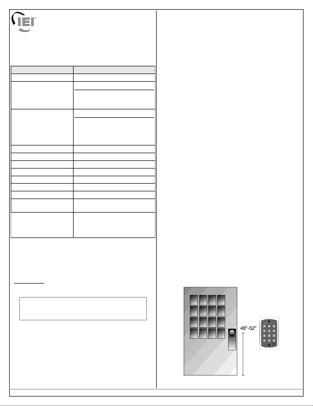
Mounting the Keypad
The keypad is designed to be flush mounted using a standard UL
Listed single-gang electrical box. Mounting height can vary
depending on requirements. An appropriate range is typically
between 48 and 52 inches on center off the floor.
For outdoor installations, use a UL Listed weatherproof back box
and seal the wire entry locations with silicone and provide a drain
hole. For additional protection, install the provided foam gasket
between the keypad and the back box. In addition, use the antioxidant grease pack for the wire harness connectors.
Note: For additional information about installing and
programming the 2000e/2000eM keypad please contact
IEI at 1- 800-343-9502
Document #: 6104402, Rev 2.0 Page 1 of 8
Page 2
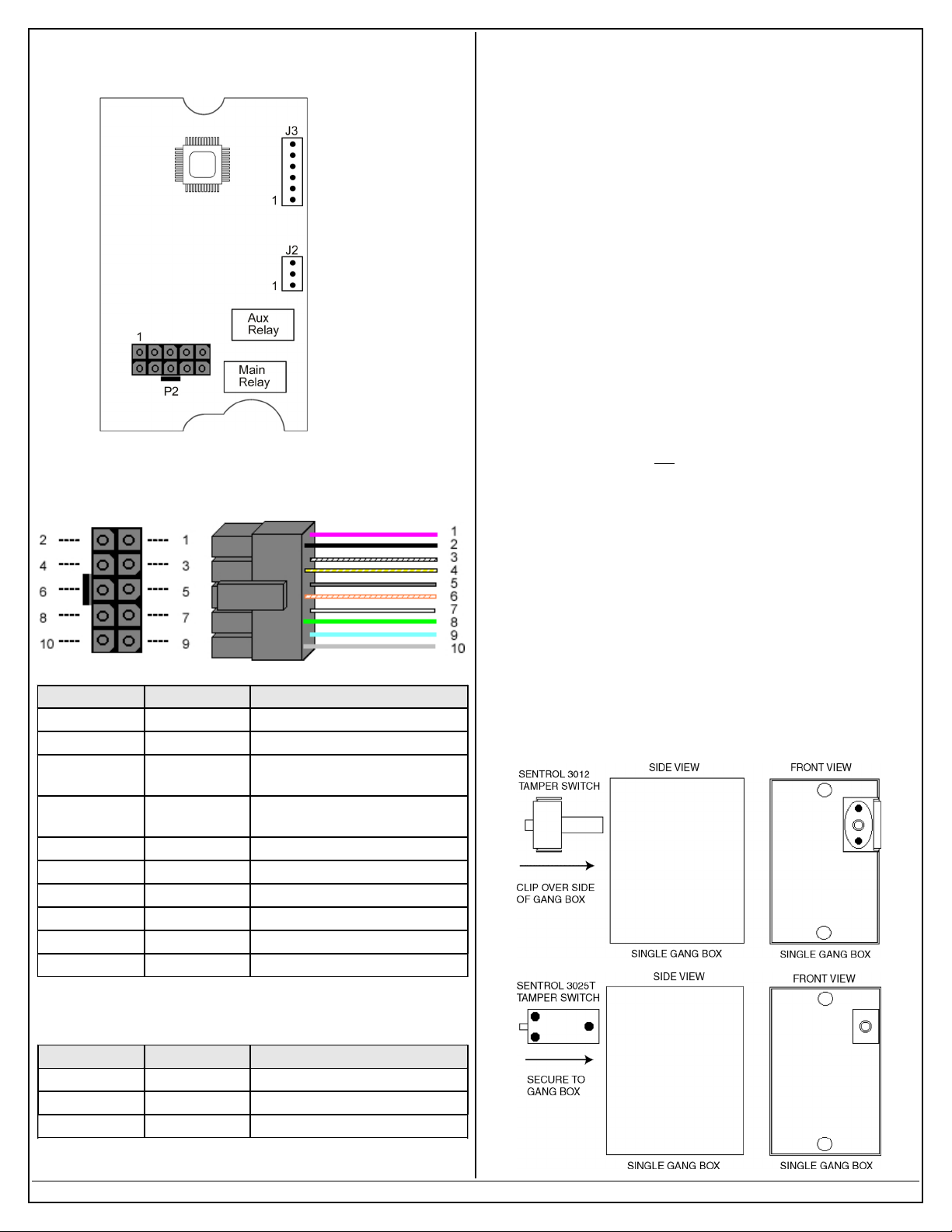
Circuit Board Diagram
Main Wire Harness (P2)
Note: J3 is for
use only with the
2000-8EX
Output Module.
UL Requirements
The 2000e/2000eM keypad is a UL Listed access control unit. This
section contains information regarding the requirements necessary
to meet UL compliance.
Wiring methods shall be in accordance with the National Electrical
Code (ANSI/NFPA70), local codes, and the authorities having
jurisdiction.
All wires and cables used must be a minimum of 22 AWG,
stranded and shielded UL Listed and/or recognized wire suitable
for the application. In addition, input and output cables that extend
from the unit must be shielded, twisted pair. Ground the shield
only at one end, usually the circuit end.
All interconnecting devices (ie. door contacts, REX, locking
devices, alarm devices, doorbell, etc.) must be UL Listed.
A UL Listed access control power limited power supply, capable
of 4 hours standby, must be used to power the keypad.
A minimum of three user codes must be programmed for
controlling access.
The following Wiegand card formats were not evaluated by UL:
28-bit, 29-bit, 30-bit, 31-bit, 32-bit or 36-bit (formats 2-8 from
wiegand format chart. UL did
(format 1).
8-Bit Burst Mode was not evaluated by UL.
evaluate the 26-bit card format
Pin Wire Color Description
1 Red V+ (Keypad Power)
2 Black V- (Keypad Power)
3 White/Black Wiegand Data 0/Secured Series
Data
4 White/Yellow Wiegand Data 1/Secured Series
Data
5 Brown Request to Exit (REX)/LED1
6 White/Orange Loop Common
7 White Door Position Switch Input
8 Green Main Relay Normally Open
9 Blue Main Relay Common
10 Gray Main Relay Normally Closed
Installing a Tamper Switch
To meet UL requirements, a UL Listed tamper switch must be
installed in a UL Listed single-gang box used for mounting the
keypad. The tamper switch must activate if the keypad is
removed from the box and must disconnect power from the lock.
The lock must be a fail-secure device, meaning the lock remains
locked when power is removed.
In addition, once the tamper device is activated, it must be
configured so that it can only be reset from within the protected
area. Only a Sentrol 3012 or Sentrol 3025T tamper switch can be
used. The diagrams below show the suggested mounting location
for each device.
Auxiliary Relay Wire Harness (J2)
Pin Wire Color Description
1 Green Aux Relay Normally Open
2 Blue Aux Relay Common
3 Gray Aux Relay Normally Closed
Document #: 6104402, Rev 2.0 Page 2 of 8
Page 3
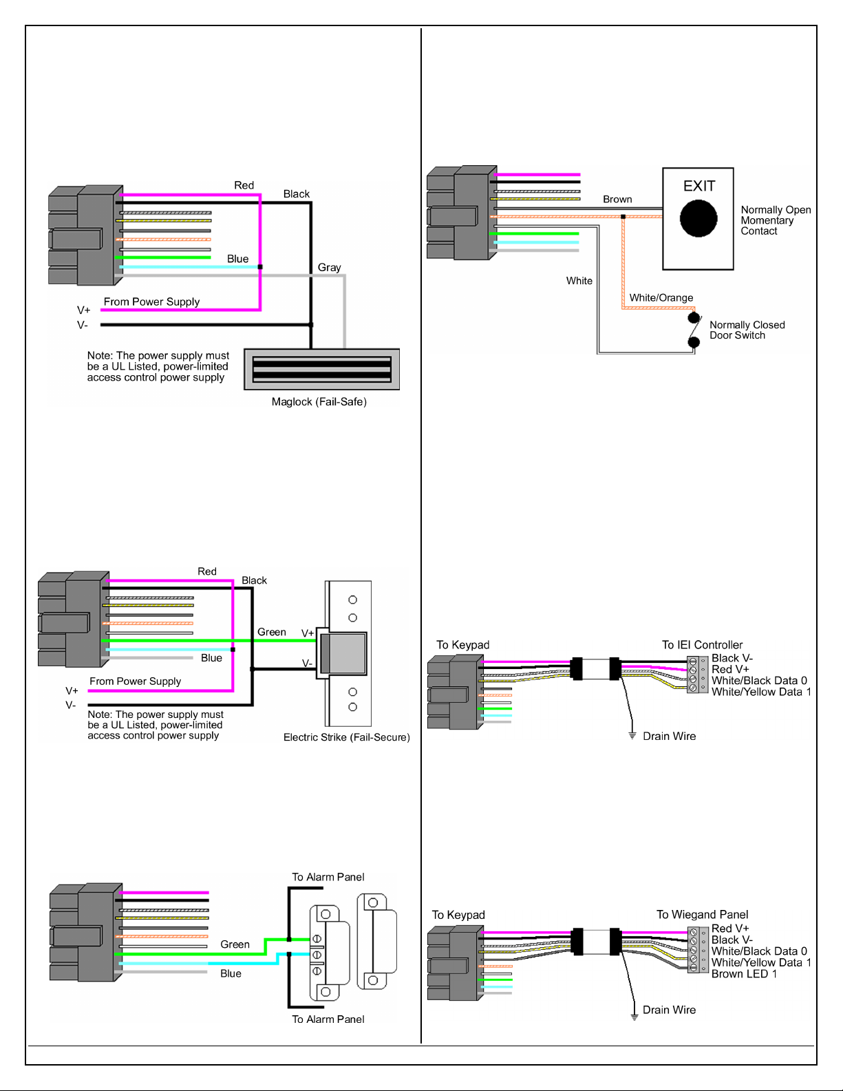
Wiring a Maglock (Fail-Safe)
Wiring the REX and Door Position Switch
1. Connect the red wire (V+) to the blue wire (common), and
then connect them to the positive on the power supply.
2. Connect the gray wire (normally closed) to the positive on the
Maglock.
3. Connect the black wire (V-) to the negative on the Maglock,
and then connect them both to the negative on the power
supply.
Wiring an Electric Door Strike (FailSecure)
1. Connect the red wire (V+) to the blue wire (common), and
then connect them to the positive on the power supply.
2. Connect the green wire (normally open) to the positive on the
strike.
3. Connect the black wire (V-) to the negative on the strike, and
then connect them both to the negative on the power supply.
1. Connect the brown wire (REX Input) to the normally open
connection on the REX device.
2. Connect the white/orange wire (loop common) to the common
on the REX device and the common on the door switch.
3. Connect the white wire (door loop) to the normally closed
connection on the door switch.
Note: By default, the forced door and propped door outputs are
assigned to the audio alerts. When you power up the keypad for
the first time and door contacts are not connected, you may hear
audio alert #1 immediately followed by audio alert # 2 thirty
seconds later. If you are not using door contacts you must either
short the white and white/orange wires together or disable the
audio alerts.
Secured Series Front End Wiring Diagram
To use the keypad as a Secured Series Front End, connect the red,
black, white/black and white/yellow wires, on the main keypad
wire harness, to the corresponding terminals on the Secured Series
Door Control Module. The drain wire must be connected at the
controller side only. Refer to the wiring distance and gauge in the
specifications chart.
Wiegand Front End Wiring Diagram
Shunting a Normally Closed Zone
1. Connect the blue wire (common) to the common connection
on the door position switch.
2. Connect the green wire (normally open) to the normally closed
connection on the door position switch.
Document #: 6104402, Rev 2.0 Page 3 of 8
To use the keypad as a Wiegand Front End, connect the red,
black white/black, white/yellow and brown wires on the main
keypad wire harness to the corresponding terminals on the
Wiegand Control Panel. The drain wire must be connected at the
panel side only. Refer to the wiring distance and gauge in the
specifications chart.
Page 4

Changing the Master Code
Programming Users
The first step in setting up your keypad is to enter program mode
and change the master code. The default master code is 1234.
1. Enter Program Mode
Press: 99 # master code * (Yellow LED Flashes Slowly)
2. Change Master Code
Press: 1 # new master code * repeat code *
(Yellow LED Flashes Slowly)
3. Exit Program Mode
Press: * (Yellow LED Stops Flashing)
Programming a Supervisor Code
Use the following command sequence to program a supervisor
code, which is stored user location 2. The supervisor is only
allowed to add, delete and disable users .
1. Enter Program Mode
Press: 99 # master code * (Yellow LED Flashes Slowly)
2. Change Supervisor Code
Press: 2 # supervisor code * repeat code *
(Yellow LED Flashes Slowly)
3. Exit Program Mode
Press: * (Yellow LED Stops Flashing)
Selecting Secured Series Front End Mode
To select Secured Series Front End Mode, use the following steps:
1. Enter Program Mode
Press: 99 # master code * (Yellow LED Flashes Slowly)
2. Select Secured Series Front End Mode
Press: 1032 # 0 # 2 # ** (Yellow LED Flashes Slowly)
3. Exit Program Mode
Press * (Yellow LED Stops Flashing)
Selecting Wiegand Front End Mode
To select Wiegand Front End Mode, use the following steps:
1. Enter Program Mode
Press: 99 # master code * (Yellow LED Flashes Slowly)
2. Select Wiegand Front End Mode, press:
1032 # 0 # 1 # ** (Yellow LED Flashes Slowly)
3. Exit Program Mode
Press * (Yellow LED Stops Flashing)
Selecting Standalone Mode
Standalone Mode is the default operating mode. If you've changed
the operating mode and want to revert back to Standalone Mode,
use the following steps:
1. Enter Program Mode
Press: 99 # master code * (Yellow LED Flashes Slowly)
2. Select Standalone Mode
Press: 1032 # 0 # 0 # ** (Yellow LED Flashes Slowly)
3. Exit Program Mode
Press * (Yellow LED Stops Flashing)
(Standalone Mode Only)
The unit can hold up to 500 users. Codes are 1 to 10 digits in
length.
Command/Action Keys to Enter/Details
Add Standard User (short) user location # code * code *
Add Standard User with
Specific Unlock Time
Add Enhanced User
Add User to Trigger Specific
Outputs (Lock, OUT2-10)
Disable User
Delete User user location # **
unlock time # user location #
code * code *
60 # user type # user location #
code * code *
59 # outputs # user location #
code * code * (1 = Lock, 2 =
OUT2, 3 = OUT 3, Etc)
56 # 0/1 # user location # **
(0 = enabled; 1 = disabled)
User Types
(Standalone Mode Only)
User Types Description
A toggle user latches the Lock Output like an on/off
Toggle User
(0)
Standard User
(1)
Lockout User
(3)
Single Use
Code (5)
Emergency
User (7)
Duress User
(8)
Two-Part User
Type A (9)
Two-Part User
Type B (10)
switch. When you enter the code the first time, the
Lock Output is activated and remains activated until
you enter any toggle code.
This user type is a standard timed user that activates
the lock output for the time duration programmed
with command 11 or with the master code.
A Locks Out User is used to lock out users from the
keypad. After entering a lock out code, users in a
higher user location are denied access. To clear a
lock out, enter the same lock out code you used to
enter lock out mode.
This user code can only be used once. After entering
the code, the user is deleted from memory. To verify
a single use code is still programed, enter 5 # code
*. If the code wasn't used, the green LED flashes for
½ a second.
An emergency user operates as a standard timed
user, with one exception, it can't be Locked Out by a
lock out user.
The duress user is another type of emergency user.
This user activates both the Lock and Duress
Outputs. You would use this code if you wanted to
activate an alarm, as well as gain entrance through
the door.
This user type is one half of a two-part user
combination. When you enter a type A user code,
you must enter a Type B user code to gain access
through the door. After entering the code the bi-color
LED alternates red and green. You have 15 seconds
to enter the second code.
This user type is the second half of a two-part user
combination. After entering a Type B code you must
enter a Type A code to gain access through the door.
Document #: 6104402, Rev 2.0 Page 4 of 8
Page 5

Assigning Virtual Outputs to Physical
Outputs
(Standalone Mode Only)
The keypad is equipped with nineteen Virtual Outputs and twelve
Physical Outputs. Virtual Outputs are functions that you can assign
to operate any Physical Output. Physical Outputs include the main
relay and aux relay on the keypad, the eight relays on the 20008EX Output Module and the two audio alerts on the keypad..
● Using command 10, you can assign any Virtual Output to
any Physical Output or disable a Physical Output.
● Each Physical Output can have multiple Virtual Output
assigned to it.
Assigning Outputs
(Standalone Mode Only)
Command/Action Keys to Enter/Details
Assign Outputs
Virtual Outputs Physical Outputs
1 – Lock Output 1 – Main Relay
2 – Alarm Shunt 2 – Aux Relay
3 – Propped Door 3 – External Relay 1
4 – Forced Door 4 – External Relay 2
5 – OUT2 5 – External Relay 3
6 – OUT3 6 – External Relay 4
7 – OUT4 7 – External Relay 5
8 – OUT5 8 – External Relay 6
9 – OUT6 9 – External Relay 7
10 – OUT7 10 – External Relay 8
11 – OUT8 11 – Audio Alert 1
12 – OUT9 12 – Audio Alert 2
13 – OUT10
14 – Duress Output
15 – Panic Output (see page 5)
16 – Keypad Active Output
17 – Doorbell Output*
18 – REX Input Active
19 – Door Loop Input Active
*Note: The Doorbell Output also works in both Front End Modes.
Disable Virtual Output 10 # virtual output # 0 # **
Disable Physical Output 10 # 0 # physical output # **
Programming the REX/Door
Loop Outputs (Lock, OUT2-10)
Note: The default output settings are: Lock Output = Main Relay;
Alarm Shunt = Aux Relay; Forced Door = Audio Alert 1; Propped
Door = Audio Alert 2.
10 # virtual output # physical
output # **
Note: The keypad is equipped
with only two relays. The
Output Expansion Module
(2000-8EX) is required to use
additional outputs.
49 # outputs # input # **
Outputs: Lock =1, OUT2 = 2,
OUT3 = 3, OUT4 = 4, etc
Input: REX = 0; Door Loop = 1)
Programming Output Times
(Standalone Mode Only)
Command/Action Keys to Enter/Details
Change Lock Output Time 11 # time # 0 # ** (1-255 sec)
Set OUT2 Time Duration 12 # ttt # mmm # **
Set OUT3 Time Duration 13 # ttt # mmm # **
Set OUT4 Time Duration 14 # ttt # mmm # **
Set OUT5 Time Duration 15 # ttt # mmm # **
Set OUT6 Time Duration 16 # ttt # mmm # **
Set OUT7 Time Duration 17 # ttt # mmm # **
Set OUT8 Time Duration 18 # ttt # mmm # **
Set OUT9 Time Duration 19 # ttt # mmm # **
Set OUT10 Time Duration 110 # ttt # mmm # **
Set Propped Door Time 44 # time # 0 # ** (10-990 sec)
Set Forced Door Time 45 # time # 0 # ** (10-990 sec)
Note: OUT2-10: ttt = time units; mmm = multiplier. Ex: “12 # 2 #
5 # **” = 10 seconds (2 time units multiplied by 5 seconds = 10
seconds). The maximum value of ttt and mmm is 255 (255 x 255).
The default output times (Lock Output, OUT2-10) are 5 seconds.
To toggle the output enter 0 for both ttt and mmm; Ex: 12 # 0 # 0 #
**.
Programming Keypad Options
(Default settings are in bold)
Command/Action Keys to Enter/Details
Change Keypad Options 30 # option # setting # **
Option Setting
0 – Audio Keypress Feedback 0 = Disabled 1 = Enabled
1 – Visual Keypress Feedback 0 = Disabled 1 = Enabled
2 – Auto Entry 0 = Disabled 1 = Enabled
3 – Error Lockout 0 = Disabled 1 = Enabled
4 – User Lockout 0 = Disabled 1 = Enabled
5 – Two-Part Users 0 = Disabled 1 = Enabled
6 – Keypad Backlighting 0 = Disabled 1 = Enabled
7 – Keypad Backlight Dimming 0 = Disabled 1 = Enabled
8 – REX Processing Select 0 = Only when
door closed
9 – Red LED Dimming 0 = Off when
backlighting dim
10 – Door Loop Output
Processing
16 – Secured Series In/Out 0 = Records IN 1 = Records Out
18 – 8-Bit Burst Output 0 = Disabled 1 = Enabled
19 – WFE Red LED Select 0 = Disabled 1 = Enabled
20 – WFE Red LED Active
State
21 – WFE Green LED Select 0 = Disabled 1 = Enabled
22 – WFE Green LED Active
State
Note: WFE means Wiegand Front End
0 = Not when
lock latched
0 = Low 1 = High
0 = Low 1 = High
1 = Always
1 = Always On
1 = Always
Document #: 6104402, Rev 2.0 Page 5 of 8
Page 6

Programming Keypad Parameters
Wiegand Format Chart
(Default settings are in bold)
Command/Action Keys to Enter/Details
Change Keypad Parameters 32 # parameter # value # **
Parameter Value
0 – Duress Output Duration 1 – 255 Seconds (default = 5)
1 – Panic Output Duration* 1 – 255 Seconds (default = 5)
2 – Error Lockout Threshold 1 – 50 Attempts (default = 3)
3 – Error Lockout Duration 1 – 255 Seconds (default = 10)
4 – Auto-Entry Count 2 – 10 Digits (default = 4)
7 – Auto-Entry Keypress
Timeout
10 – Wiegand Format 1 – 8 (default = 1, 26-Bit)
11 – Wiegand Pulse Width 1 – 255 (default = 8, 160µS)
12 – Wiegand Interpulse Spacing 1 – 255 (default = 32, 640µS)
Note: Refer to the Wiegand Format Chart below for parameter 8.
Change Wiegand Parameters 34 # parameter # value # **
Parameter Value
0 – Wiegand Site ID Refer to Wiegand Format Chart
1 – Wiegand Group ID Refer to Wiegand Format Chart
Note: The default setting for both settings is 0.
*Note: The Panic Output is activated by pressing the * and # keys
at the same time. This is used in case of emergency to activate an
auxiliary alarm device, such as a siren, that is used to indicate an
emergency condition only. This output should not be used to gain
access. All access control functionality should be programmed and
remain separate from the Panic Output functionality.
2 – 15 Seconds (default = 2)
Resetting the Keypad
Note: This does not reset the keypad operating mode.
Command/Action Keys to Enter/Details
Reset Defaults Only 40 # 00000 # 00000 # **
Reset Entire Keypad 46 # 00000 # 00000 # **
The keypad supports the following Wiegand formats (parameter
10).
Format
Value
1 26 bit 65535 255 N/A
2 28 bit 32767 255 N/A
3 29 bit 524287 255 N/A
4 30 bit 65535 255 15
5 31 bit 65535 255 31
6 32 bit 8191 2047 63
7 36 bit 999999 1023 N/A
8 29 bit 524287 255 N/A
Wiegand
Format
Largest
PIN Value
Largest
Site Value
Largest
Group
Value
Wiegand Data
When the keypad is configured in Wiegand mode, the keypad data
is sent as a complete Wiegand data packet, as though you
presented a card.
For example, when programming a user into an IEI Door Control
Module, you must program the user as though you were
programming a card. After entering the command to program a
card user, enter the code on the 2000e/eM keypad to send the data
to the controller.
Please refer to the Wiegand Interface Module instructions 6065700
Rev 1.0, the HubMax II Instructions 6065034 Rev 3.4 and the Hub
MiniMax II instructions 6055037 Rev 3.3 for complete details.
LED/Sounder Indications
Indicator Description
Steady Red* Door Locked
Steady Green* Door Unlocked (timed or latched)
Yellow Flashing Slowly Program Mode
Solid Yellow Program Error or Error Lockout
Alternating Red/Green Awaiting 2
LED's Cycling Left to Right Over Voltage Warning
LED's Cycling Right to Left Under Voltage Warning
3 Rapid Beeps Invalid Code
Pair of Double Beeps User Lockout Activated
Single Double Beep User Lockout Canceled
1 Long Beep, 1 Short Beep Access Denied, User Disabled
1 Long Beep, 3 Short Beeps Access Denied, User Lockout
1 Long Beep, 5 Short Beeps Access Denied, Code Mismatch
6 Quick Beeps Toggle Mode Activated
Sounder ¼ sec on, ¼ sec off Audio Alert 1
Beep Every 2 seconds Audio Alert 2
nd
PIN of Two-Part User
*Note: The Red/Green LED descriptions above are for Standalone
and Secured Series Mode only. The operation of these LED's in
Wiegand Mode is determined by the LED control wire (brown)
and how it is configured. The LED control is configured using
keypad options 19, 20, 21 and 22, which are programmed with
command 30.
Document #: 6104402, Rev 2.0 Page 6 of 8
Page 7

Wiring the 2000-8EX Output Module
If the Output Module is within 18 inches of the keypad, use the 6conductor wire harness, supplied with the Output Module, to make
the connection. If your Output Module is located more than 18
inches from the keypad (up to a maximum of 100 feet), you must
cut the wire harness in half and plug one half into the keypad the
other into the Output Module. Then connect the two using 22
AWG stranded and shielded cable. Make sure you connect the
wire harness pin to pin (pin 1 on the Output Module to pin 1 on the
keypad and so on). You must connect the drain wire from your
cable to the negative on your keypad (the black wire to your power
supply).
Performing the Programming Mode
Loopback
The keypad has a special loopback connection you can make to
enter program mode if you do not know the master code. Use the
following steps below and refer to the diagram.
Note: This procedure should only be performed by a qualified
security or lock industry professional.
1. Power down the keypad.
2. Connect the white/yellow, brown and white wires together and
disconnect any other connections to these wires.
3. Power up the keypad
4. Change the master code or default the keypad
5. Power down the keypad and remove the loopback connections
and reconnect any other wiring to these wires.
6. Power up the keypad.
Performing the Keypad Self-Test
After installing the keypad, IEI recommends that you perform the
keypad self-test once a year to ensure that the keypad is working
properly.
1. To perform the self-test, with the unit powered up, press the
following keys on the keypad: 7890#123456*
2. If all 12 key presses are accepted, the keypad enters self-test
mode.
3. The LEDs then turn on one at time with a beep in the
following order Red, Yellow then Green.
4. After the Green LED, the unit then flashes an LED to indicate
which operating mode the keypad is programmed mode.
Below shows which LED flashes for each mode:
● Standalone Mode: Red Flash
● Wiegand Front End Mode: Green Flash
● Secured Series Front End Mode: Yellow Flash
followed by rapid yellow flicker.
Note: If the unit is not connected to a controller in
Secured Series Front End Mode, the yellow LED
turns on solid after the yellow flash. Press the *
key to clear.
Document #: 6104402, Rev 2.0 Page 7 of 8
Page 8

International Electronics, Inc.
427 Turnpike St.
Canton, MA 02021 U.S.A.
Phone: 800-343-9502, 781-821-5566
Fax: 781-821-5566
Website: www.ieib.com
Document #: 6104402, Rev 2.0 Page 8 of 8
 Loading...