

Page 1
7
8 9
4 5 6
1 2 3
0
7
8 9
4 5 6
1 2 3
0
7
8 9
4 5 6
1 2 3
0
7
8 9
4 5 6
1 2 3
0
Installation/Owner’s Manual
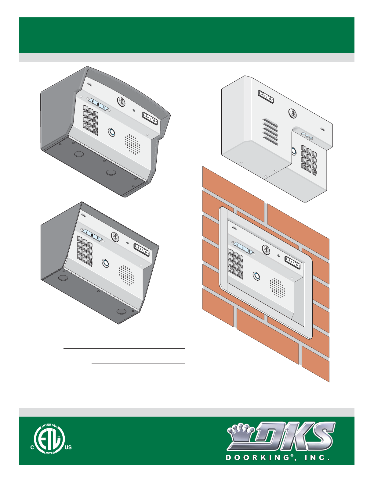
Model 1812 Access Plus
Model 1812 Access Plus
Model 1812 Access Plus
PC Programmable Residential Telephone Intercom/Access Control System
Use this manual for circuit board 1970-010 Revision G or higher.
Control a main door, gate and six additional RS-485 entry points.
Surface Mount Curved
Wall Mount
1812-162-G-12-10
Surface Mount
Date Installed:
Installer/Company Name:
Phone Number:
Leave Manual with Owner
Circuit Board
Serial Number
and Revision Letter:
Copyright 2010 DoorKing, Inc. All rights reserved.
Flush Mount
UL Listed
TM
Copyright 2009 DoorKing, Inc. All rights reserved.
Page 2

Page 3
SPECIFICATIONS
7
8
9
4 5
6
1
2 3
0
7
8 9
4 5
6
1 2 3
0
7
8 9
4
5 6
1 2
3
0
7
8
9
4
5
6
1
2
3
0
For Model 1812 Access Plus with circuit board 1970-010 Rev G or higher ONLY.
J1
1
2
3
4
5
6
7
8
9
10
11
12
13
14
15
16
17
18
Both Boards Together - 1970-010
Features
• Unique telephone communication system allows homeowners to use their telephone as an intercom to speak to a guest
at a front door or gate, and to control access to their property.
• IP Addressable – program from your PC using the DoorKing programming software via a LAN or WAN connection, or
via a built-in modem.
• Up to five (5) 1812 Access Plus units can be connected together and programmed from a single computer or phone.
• Two internal relays allow the system to control a main entry gate plus a pedestrian access gate.
• Control up to six (6) additional entry points with card readers, keypads or wireless RF via RS-485 connection.
• 100 card / transmitter / keypad codes (50 with phone numbers, 50 as access only).
• Holiday schedule.
• 500 event transaction buffer.
• Unique distinctive ring.
• Unit connects directly to the homeowners existing telephone line. No additional monthly expense for a second telephone line.
• Built in call waiting assures that incoming calls or guest calls are not missed.
• Call Forwarding.
• Up to 27 preprogrammed dial-out telephone numbers.
• Answer machine bypass feature. Allows the homeowner to log into the 1812 even after an answering machine has already
picked up the call.
• Built-in clock / calendar.
• Do-not-disturb time zone.
• Four hold-open time zones.
• Access code time zones.
• Call forwarding time zone.
• 10 temporary access codes.
• Unit can be programmed to work with PBX and KSU phone systems.
J
4
1
2
3
4
5
6
7
RS-485
8
RX
BAD
DNS
J1
LAN
DOWN
RJ-45
SW
ON
Jack
1
(Cat5)
MODEM
1972-010
J3
KEYPAD
1970-010
J2
23
4567
8
91
0
MASTER
CODE
MIC VOL
SPEAKER
VOL
111
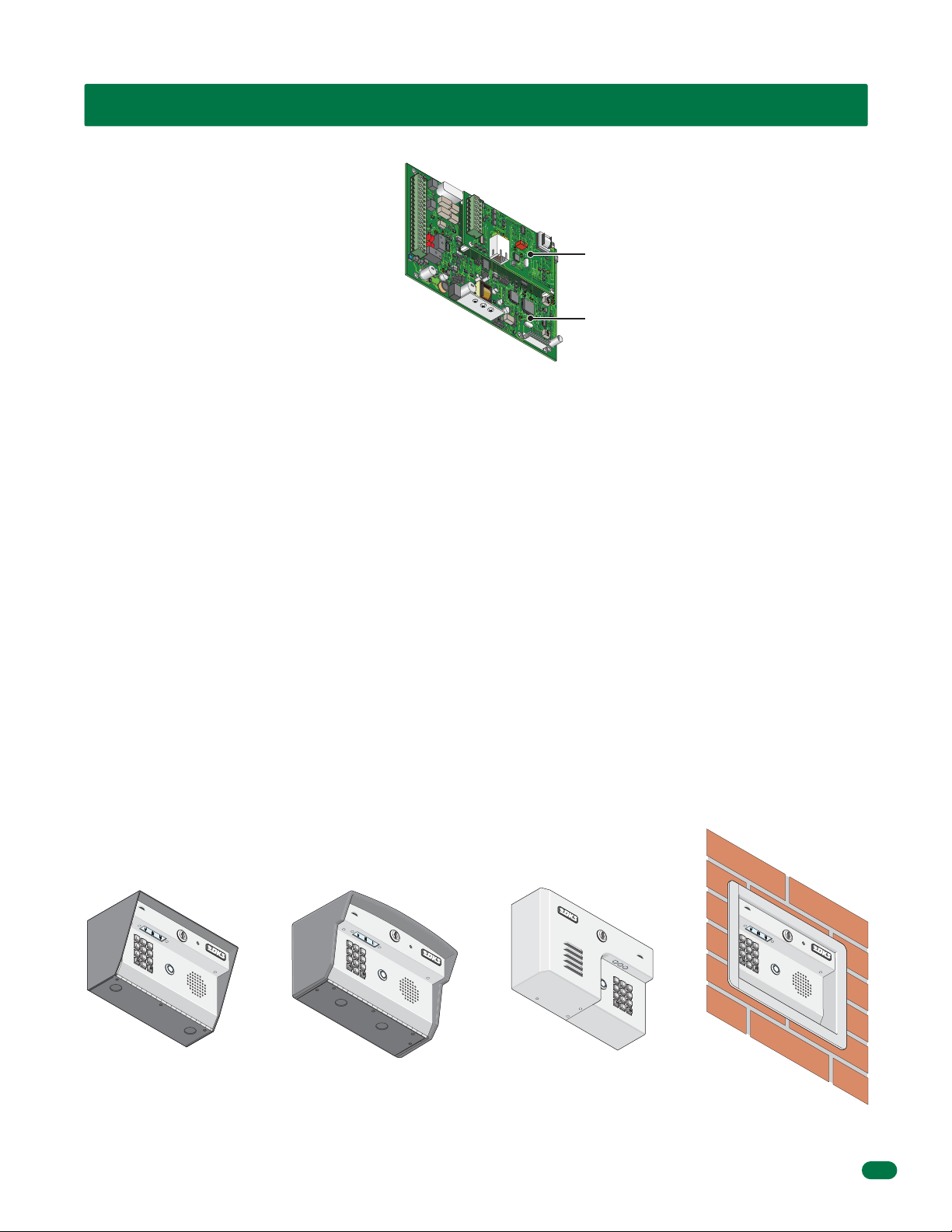
Interface Board
Control Board
7
Surface Mount
Surface Mount Curved
Wall Mount
Flush
Mount
DoorKing, Inc. reserves the right to make changes in the products described in this manual without notice and without obligation of DoorKing, Inc. to notify any persons of any such
revisions or changes. Additionally, DoorKing, Inc. makes no representations or warranties with respect to this manual. This manual is copyrighted, all rights reserved. No portion of this
manual may be copied, reproduced, translated, or reduced to any electronic medium without prior written consent from DoorKing, Inc.
1812-162-G-12-10
1
Page 4
SPECIFICATIONS
7
8
9
4
5
6
1
2
3
0
7
8
9
4 5
6
1
2
3
0
7 8 9
4 5 6
0
7 8 9
4 5 6
0
Surface Mount Dimensions
10” 5.25”
2.5”
1 2 3
2.875”
875” Dia
1.75”
1.125”1.125”
Surface Mount Curved Dimensions
11” 6.25”
6.125”
1.125” Dia
5”
2.5”
3”
2
1 2 3
875” Dia
2.5”
6.75”
1.125” Dia
2.5”
5.5”
3”
7
2”
3.75”3.125”
1812-162-G-12-10
Page 5
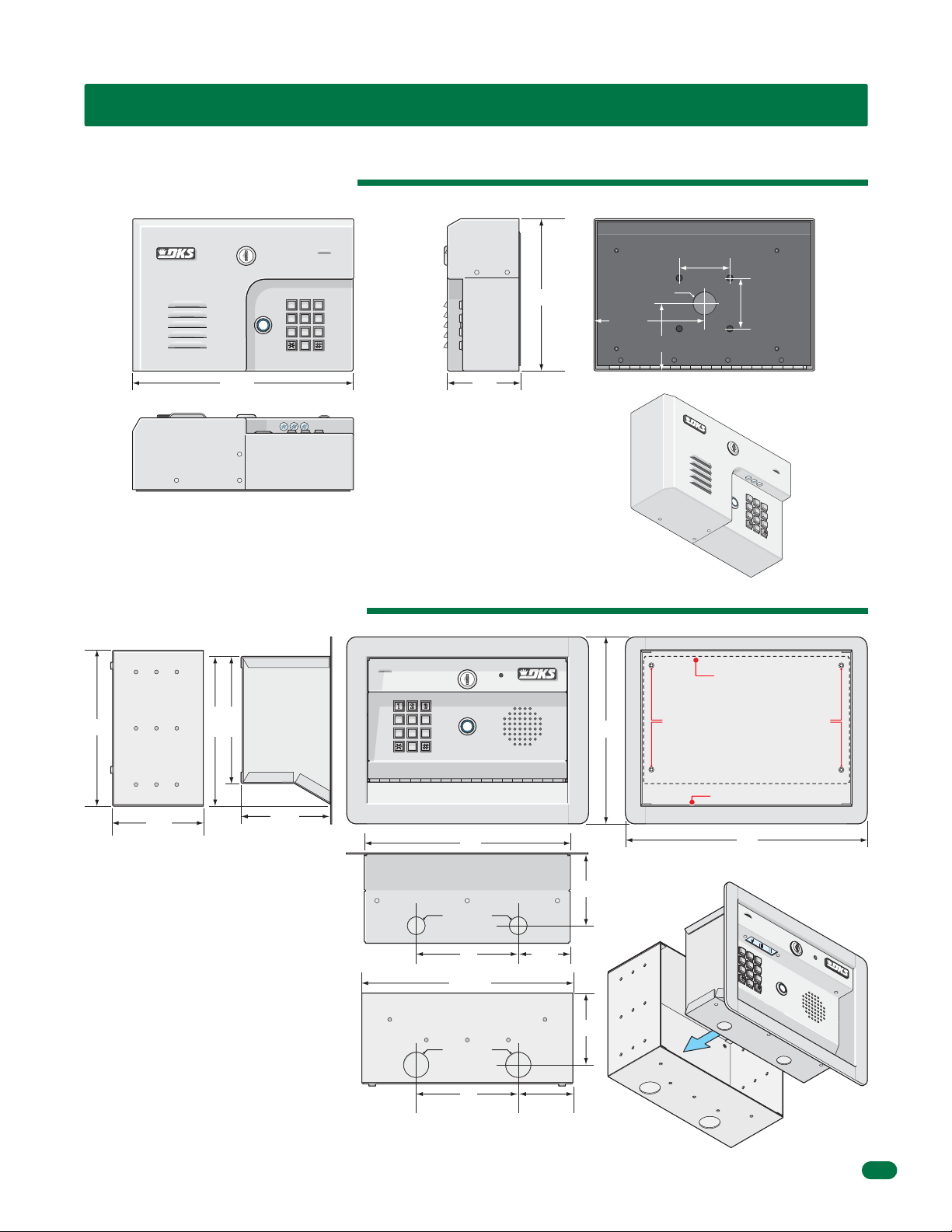
Wall Mount Dimensions
7
8
9
4
5
6
1 2
3
0
7 8 9
4 5 6
1 2 3
0
7 8 9
4 5 6
0
7
8
9
4
5
6
1
2
3
0
SPECIFICATIONS
2.5”
10.75” 3.5”
Flush Mount Dimensions
Rough-In Box
7.5”
7.25”
Flush Box
6.25”
1 2 3
7.325”
9.25”
1.125” Dia
5.375”
2.5”
3.375”
7
Flush Box
Bolt holes (4) to secure flush box
inside rough-in box.
1812-162-G-12-10
4.5”
4.25”
Flush Box
Rough-In Box
10”
.875” Dia
5” 2.5”
10.25”
1.25” Dia
5”
2.625”
3.5”
3.5”
ough-In
R
Box
Rough-In Box
12”
Flush
ox
B
3
Page 6

TABLE OF CONTENTS
SPECIFICATIONS
Features
Surface Mount Dimensions
Surface Mount Curved Dimensions
Wall Mount Dimensions
Flush Mount Dimensions
Important Notices FCC - United States, DOC - Canada
General Information Installation Guidelines and Safety Information
SECTION 1 - INSTALLATION
1.1 Mount the 1812 Access Plus
Different Mounting Configurations of the 1812 Access Plus Models
1.2 Install By-Pass Board for “Telephone Mode” Configurations
1.3 Telephone Line Wire
1.4 Power Wiring
1.5 Grounding and Surge Suppression
1.6 Wire One 1812 to a Telco Line - Telephone Mode
1.7 Wire One 1812 to the Internet - Telephone Mode
1.8 Wire Multiple 1812s: Telco/Internet - Telephone Mode
1.9 Wire One 1812 - Intercom Mode
1.10 Wire Multiple 1812s - Intercom Mode
1.11 Main Terminal Description
1.12 Access Plus Interface Board
1.12.1 8-Pin RS-485 Connector Description
RS-485 Daisy Chain Wiring
RS-485 Configurations, Samples of Multiple 1812 Configuration Connections: Telephone Mode or Intercom Mode
1.12.2 Network Connections
1.12.3 Phone Modem Connections
1
1
2
2
3
3
4
5
8
8
9
11
12
13
13
14
15
16
17
18
19
19
19
20
21-22
23-24
25
SECTION 2 - PROGRAMMING
2.1 Programming the Master Code
2.2 Programming Methods
2.3 Programming the Network Setup for a Computer
2.3.1 Enable / Disable TCP / IP Support - System Reboot
2.3.2 Set the 1812 IP Address (reboot required)
2.3.3 Sub-Net Mask (reboot required)
2.3.4 Set the Gateway (router) IP Address (reboot required)
2.3.5 Set the Port Number (reboot required)
2.4 System Parameters Programming
Programming from the System Keypad
Programming from a Touch-Tone Telephone
Quick Reference Table
2.4.1 Phone Mode or Intercom Mode
2.4.2 Single or Multiple Systems
2.4.3 System Attention Number
2.4.4 Single or Double Ring
2.4.5 Number of Home Phone Rings Before 1812 Hangs Up
2.4.6 Talk Time
2.4.7 Relay Strike Time
2.4.8 Tone Open Numbers
2.4.9 Answer Incoming Call on X Rings
2.4.10 Hang Up Tone Number
2.4.11 Call Waiting
26
26
27
28
28
28
29
29
29
30
30
30
31
32
32
32
32
32
33
33
33
34
34
34
4
1812-162-G-12-10
Page 7

TABLE OF CONTENTS
2.4.12 Turn Speaker On / Control Relay from Off-Site Call
2.4.13 Set Call Forwarding Microphone Gain and Speaker Volume
2.5 Directory Codes
2.5.1 Directory Codes 24 – 50 Programming “Dial Phone Number”
2.5.2 Delete a Phone Number from Directory Codes 24 – 50
2.5.3 Delete ALL Phone Numbers from Directory Codes 24 – 50
2.6 Access Codes to Operate Access Control Devices
2.6.1 “Simple” Access Code Programming (Relays 1&2: 24/7 Operation)
2.6.2 Number of RS-485 Devices Connected (Up to 6)
2.6.3 RS-485 Device(s) Function during Communication Failure
2.6.4 “Time Zone Restricted” Access Code Programming
2.6.5 Delete an Access Code (Simple and Time Zone Restricted)
2.6.6 Delete All Access Codes for the Same Type of Device (Simple and Time Zone Restricted)
2.6.7 “Temporary” Access Code Programming
2.6.8 Delete a “Temporary” Access Code
2.6.9 Delete All “Temporary” Access Codes
2.7 Time Functions
2.7.1 Time and Date Calendar Chip Programming
2.7.2 Call Forward Phone Number Programming
2.7.3 Call Forward - ON/OFF or Timed Schedule Activation
2.7.4 Do Not Disturb Schedule (DND)
2.7.5 Relay Hold Schedules (Up to 4)
2.7.6 Time Zones (Up to 4)
2.8 Miscellaneous
2.8.1 Restore Factory Defaults
2.8.2 Erase Transaction Log
34
35
35
35
35
35
36
36
36
36
37
37
37
38
38
38
39
39
39
40
40
41
41
42
42
42
SECTION 3 - ADJUSTMENTS
Speaker Volume
Microphone Gain
Interface Board LED Status
System Keypad and Push to Call Button
SECTION 4 - USER INSTRUCTIONS
4.1 Resident Operating Instructions
4.1.1 Granting or Denying a Guest Access
4.1.2 Call Waiting
4.1.3 Dial-Out Phone Numbers
4.1.4 Access Codes
4.2 Remote Operation
4.2.1 Remote Programming (Home Phone or Off-Site Phone)
4.2.2 Remote Relay Activation (Off-Site Phone)
4.2.3 Relay Activation from Homeowner’s Phone
4.2.4 Relay Activation Check from Homeowner’s Phone
4.2.5 Initiate Talk and Listen to 1812 when it has not been activated
SECTION 5 - MAINTENANCE
5.1 Troubleshooting
5.2 Phone Line Polarity
5.3 Isolating Noise Problems
5.4 Troubleshooting Table
5.5 1812 Access Plus Wiring Schematic
5.6 Accessories
5.7 Programmed Information Log Sheets
Master Code, Relays, Access Codes and Schedule Log Sheet Directory Code / Dial-Out Phone Numbers Log Sheet;
Access Code Log Sheets (50 with phone numbers, 50 as access only), 1-10 Temporary Access Codes Log Sheet and extra log sheet.
1812-162-G-12-10
43
43
43
43
43
44
44
44
44
44
44
45
45
45
45
45
46
46
46
47
48
48-49
50
50
51-57
5
Page 8

Important Notices
FCC – United States
This equipment has been tested and found to comply with the limits for a class A digital device, pursuant to Part 15 of the FCC
Rules and Regulations. These limits are designed to provide reasonable protection against harmful interference when the
equipment is operated in a commercial environment. This equipment generates, uses, and can radiate radio frequency energy
and, if not installed and used in accordance with the instruction manual, may cause harmful interference to radio communications. Operation of this equipment in a residential area is likely to cause harmful interference in which case the user will be
required to correct the interference at his own expense.
FCC Registration Number: DUF6VT-12874-OT-T
DOC - Canada
The Canadian Department of Communications label identifies certified equipment. This certification means that the equipment
meets certain telecommunications network protective, operational, and safety requirements. The Department does not guarantee the equipment will operate to the users satisfaction.
Before installing this equipment, users should ensure that it is permissible to be connected to the facilities of the local telecommunications company. The equipment must also be installed using an acceptable means of connection. The customer should be
aware that compliance with the above conditions may not prevent degradation of service in some situations.
Repairs to certified equipment should be made by an authorized Canadian maintenance facility designated by the supplier. Any
repairs or alterations made by the user to this equipment, or equipment malfunctions, may give the telecommunications
company cause to request the user to disconnect the equipment.
Users should ensure, for their own protection, that the electrical ground connections of the power utility, telephone lines, and
internal metallic water pipe system, if present, are connected together. This precaution may be particularly important in rural
areas.
CAUTION: Users should not attempt to make such connections themselves, but should contact the appropriate electric inspection authority, or electrician, as appropriate.
DOC Registration Number: 1736 4507 A
Notice:
The Load Number (LN) assigned to each terminal device denotes the percentage of the total load to be connected to a telephone
loop which is used by the device, to prevent overloading. The termination on a loop may consist of any combination of devices
subject only to the requirement that the sum of the load numbers of all the devices does not exceed 100.
Notice:
DoorKing does not provide a power transformer on units sold into Canada. Use only transformers that are CSA listed to power
the telephone entry system. The model 1812 Access Plus requires a 16.5-volt, 20 VA transformer.
6
1812-162-G-12-10
Page 9

General Information
• Prior to beginning the installation of the telephone entry system, we suggest that you become familiar with the
instructions, illustrations, and wiring guidelines in this manual. This will help insure that you installation is performed in
an efficient and professional manner.
• The proper installation of the telephone entry panel is an extremely important and integral part of the overall access
control system. Check all local building ordinances and building codes prior to installing this system. Be sure your
installation is in compliance with local codes.
• When used to control a door or pedestrian gate, try to locate the telephone entry system as near as possible to the entry
point. The unit should be mounted on a rigid wall to prevent excessive shock and vibration from closing doors or gates.
Continuous vibration and shock from slamming doors or spring-loaded pedestrian gates will damage the circuit board.
Under no circumstances should the unit be mounted directly to a moving door or gate.
• ADA mounting requirements for door control. The requirements below apply only when the telephone entry system is
being used to control entry through a public door only. If this system is used to control entry through a vehicular gate or
private entrance, the dimensions noted below do not apply.
1. If the clear floor space allows only forward approach to the system, the maximum high forward reach allowed is
48 inches above grade to the top of the keypad.
2. If the high forward reach to the system is over an obstruction of greater than 20 inches but less than 25 inches,
the maximum high forward reach allowed is 44 inches above grade to the top of the keypad.
3. If the clear floor space allows parallel approach by a person in a wheelchair, the maximum high side reach shall
be 54 inches above grade to the top of the keypad.
4. If the high side reach is over an obstruction of 24 inches or less, the maximum high side reach allowed is 46
inches above grade to the top of the keypad.
• When used to control a vehicular gate with an automatic gate operator, the telephone entry system must be
mounted a minimum of ten (10) feet away from the gate and gate operator, or in such a way that a person cannot
operate the entry system and/or touch the gate or gate operator at the same time.
• Be sure that the system is installed so that it is not directly in the traffic lane. Goose neck mounting post and kiosks
work well for these type systems. When planning where to locate the system, take into consideration traffic lane layouts,
turn around lanes for rejected access, conduit runs, power availability, etc.
• Environmental factors must also be taken into account. Surface mount units are designed for direct outdoor
installations, however it is preferable to protect them from direct exposure to driven rain or snow whenever possible.
Flush mount units must be protected from direct exposure to the elements.
• This telephone entry system contains a number of static sensitive components that can be damaged or destroyed by
static discharges during installation or use. Discharge any static prior to removing the circuit board from the lobby panel
by touching a proper ground device.
• Instruct the end user to read and follow these instructions. Instruct the end user to never let children play with or
operate any access control device. This Owner’s Manual is the property of the end user and must be left with them
when installation is complete.
1812-162-G-12-10
7
Page 10
SECTION 1 - INSTALLATION
Installation of the 1812 Access Plus Telephone Entry System involves the installation of the hardware, by-pass board, and the
wiring of these components. Be sure that all dirt, metal or wood debris is removed from inside after mounting it. Any debris
inside could damage the control board and cause the 1812 Access Plus system to malfunction during operation.
When the 1812 Access Plus is used to control a vehicular gate with an automatic gate operator, it must be
mounted a minimum of ten (10) feet away from the gate and gate operator, or in such a way that a person
cannot operate the 1812 Access Plus system and/or touch the gate or gate operator at the same time.
WARNING
1.1 Mount the 1812 Access Plus
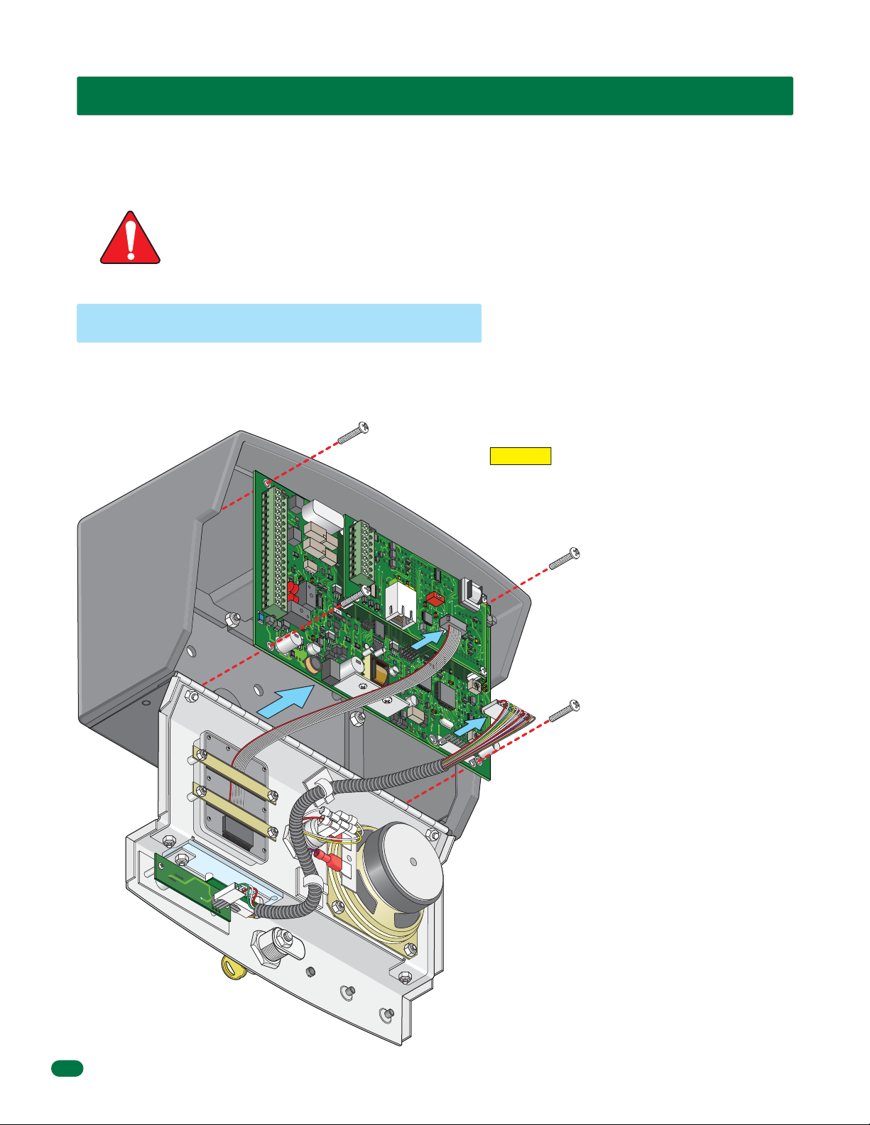
Use the specification dimensions on pages 2 and 3 to help with the installation of your chosen 1812 Access Plus model.
Remove the Control Board
The control board removal is the same for all models.
CAUTION The control board contains static sensitive
J1
1
2
3
4
5
6
7
8
9
10
11
12
13
14
15
16
17
18
J4
1
2
3
4
5
6
7
8
RS-485
RX
BAD
DNS
J1
LAN
DOWN
RJ-45
SW1
ON
Jack
(Cat5)
MODEM
1972-
010
J
3
K
E
Y
P
A
D
components. Discharge any static electricity from
your hands by touching a proper ground device
before removing the control board.
1. Unlock and open the 1812 door.
2. Disconnect the keypad plug and
door accessories plug from the
control board.
MA
S
TER
C
ODE
3. Remove the 4 screws.
Carefully remove control board.
Keep the control board in a
protected area during the mounting
M
IC
VO
L
installation.
1970-
010
S
P
E
J
AKE
2
R
V
O
L
6
7
89
1
0
1
112345
8
1812-162-G-12-10
Page 11
Different Mounting Configurations of the 1812 Access Plus Models
Surface and Wall mount models can be mounted directly to a wall, pilaster or post mounted using a DoorKing mounting post
(there are several different styles available). The flush mount model is designed to be mounted into a pilaster, wall or kiosk. In
any case, be sure it is securely mounted and is not subject to continuous vibration from closing doors or gates.
Mount on a Mounting Post
Use existing 4 holes in cabinet box to
bolt the surface or wall mount models
on a DoorKing mounting post. Use
the hardware that is supplied with the
mounting post.
IMPORTANT Choose
how your 1812 will
function (Telephone
Mode or Intercom
Mode) on pages 14
Note: A gooseneck mounting
post anchored in concrete
does not make a good ground.
thru 18 and run the
indicated wires to the
cabinet. Also route
RS-485 and/or network
connection wires to the
cabinet if they are to be
used. Run ALL wires
that will be needed
during the cabinet
installation.
1812-162-G-12-10
Mount Directly to a Wall or Pilaster
Use the 4 existing holes in the
cabinet box. Run conduit inside or
outside of wall or pilaster if desired.
Use appropriate hardware to mount
the cabinet (Not supplied). Be sure
that the mounting hardware does not
protrude into the cabinet where it
could cause a short.
Plastic screw anchors for
masonry if required.
(Not supplied)
Conduit
(Shown inside wall)
9
Page 12
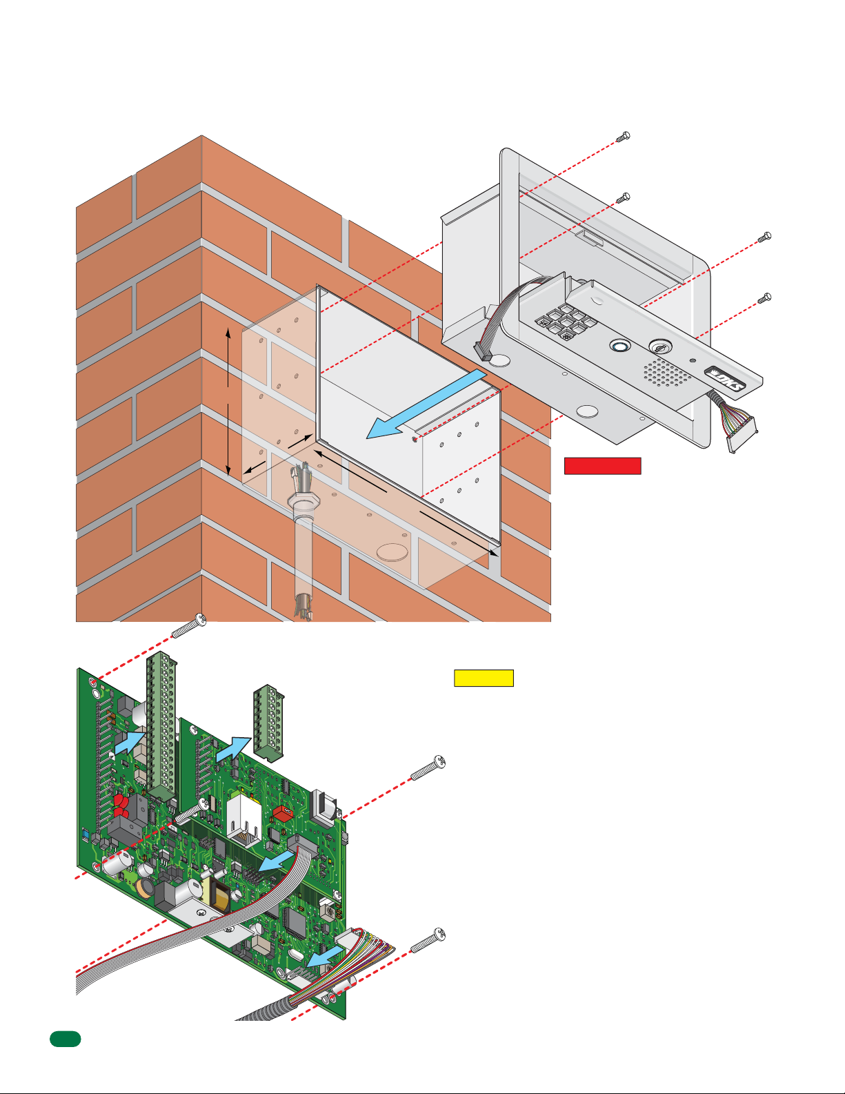
Flush Mount in a Pilaster, Wall or Kiosk
7
8 9
4 5 6
0
Mount rough-in box into the pilaster, wall or kiosk. Run conduit inside wall into bottom of rough-in box if desired.
Use appropriate hardware (Not supplied) to secure the rough-in box in place.
Bolt flush box into the
rough-in box with 4
supplied bolts.
Flush
Box
7
7.5”
Rough-In Box
4.5”
10.25”
Conduit
in Wall
IMPORTANT Choose how your 1812
will function (Telephone Mode or
Intercom Mode) on pages 14 thru 18
and run the indicated wires to the
rough-in box. Also route RS-485
and/or network connection wires to
the box if they are to be used. Run
ALL wires that will be needed during
the mounting installation.
18-Pin
Main
J1
1
2
3
4
5
6
7
8
9
10
11
12
13
14
15
16
17
18
Terminal
Connector
J
4
1
2
3
4
5
6
7
8
8-Pin
RS-485
Connector
RS
-
4
85
RX
B
A
D
DNS
J
L
1
A
N
DOW
R
N
J
-
45
S
ON
W
J
ac
1
k
(C
at
5)
M
ODE
M
MA
S
T
E
R
C
1
972
-
010
J
3
K
E
Y
PAD
ODE
the 8-pin RS-485 connector from the control board by gently pulling
them straight up. This will make wiring to the control board easier. Note
the orientation and numbering sequence of each connector to correctly
wire it.
Re-install control board by carefully routing all incoming wires around it
Re-install the Control Board
CAUTION The control board contains static sensitive
components. Discharge any static electricity from your
hands by touching a proper ground device before
re-installing the control board. Also make sure that all
dirt, metal or wood debris is removed from inside
before re-installing the board.
Remove the 18-pin main terminal connector, and if necessary,
and secure it in place with 4 screws. Re-connect the keypad plug (cable
MIC
points down) and door accessories plug (red wire goes to the left) to the
V
OL
control board.
Connect all wires to the 18-pin connector and to the 8-pin
connector if needed (See pages 19 and 20). Gently
re-connect them back on the control board. DO NOT
APPLY POWER to the 1812 at this time.
1812-162-G-12-10
1234
1970-
0
10
SP
E
J
A
K
2
E
R
V
OL
56
7
8910
1
1
Keypad
Plug
Door
Accessories
Plug
10
Page 13
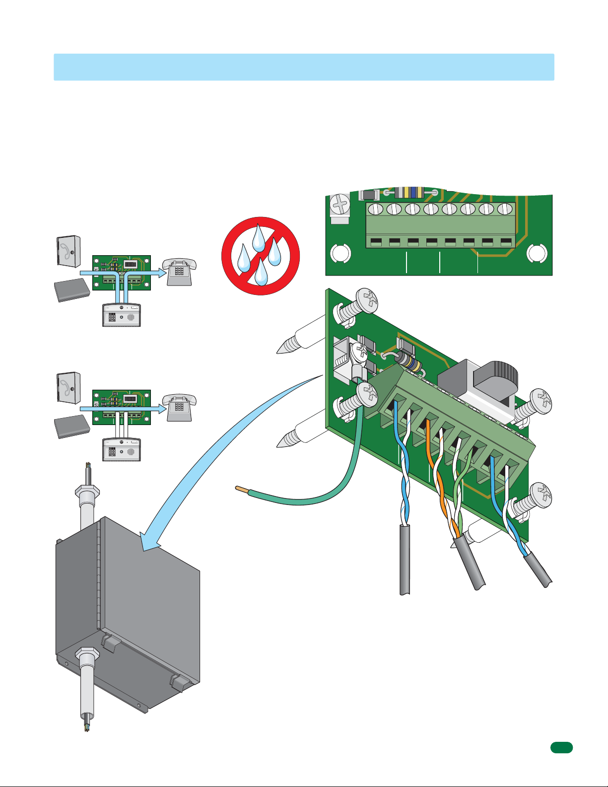
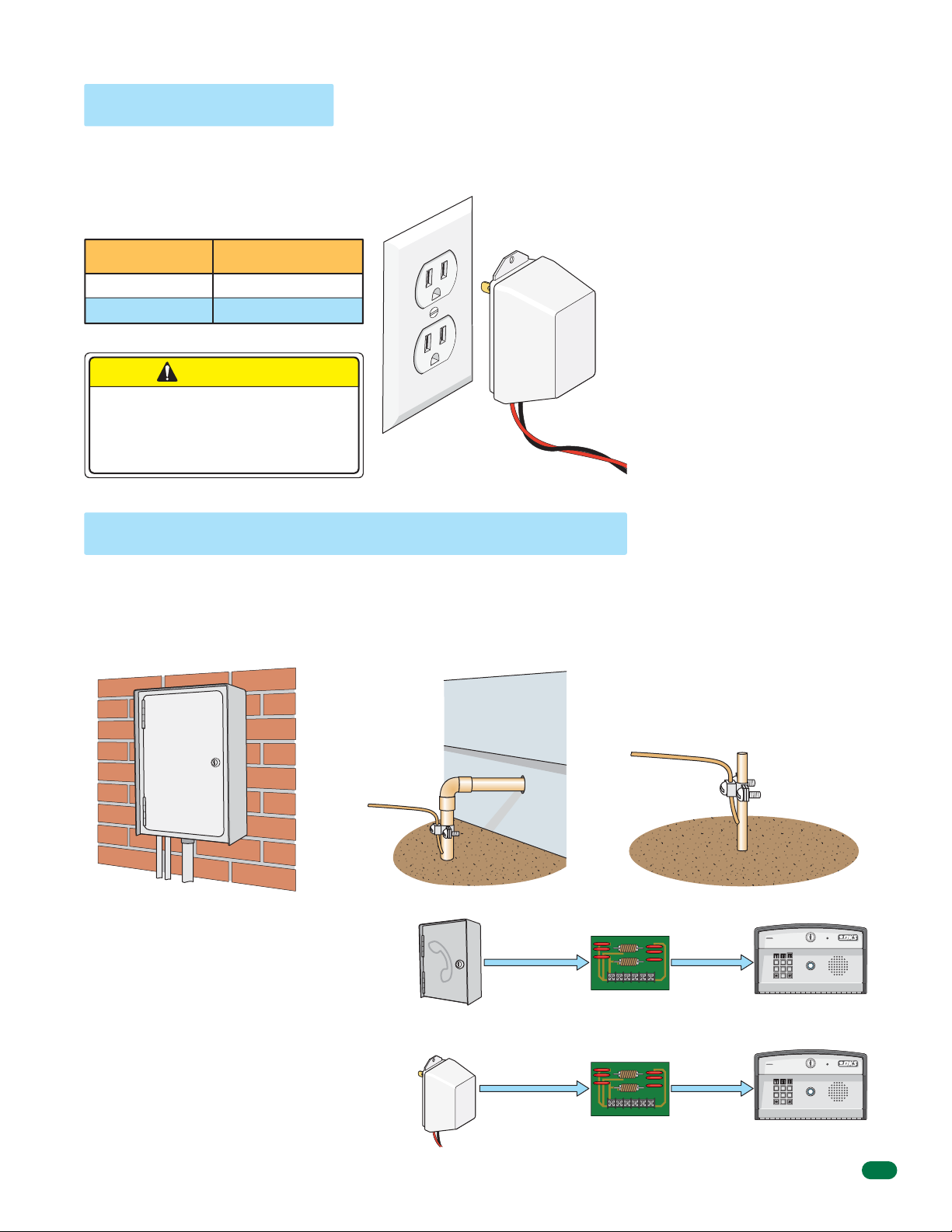
1.2 Install By-Pass Board for “Telephone Mode” Configurations
7 8 9
4 5 6
0
7 8 9
4 5 6
0
The 1812’s by-pass board provides a method to by-pass the 1812 and route the incoming telephone line directly to the
homeowner’s phone. The By-Pass board IS NOT optional when using an incoming telephone line or internet (Telephone
Mode) – it must be installed as part of the 1812 system. All telephone wires for the 1812 must pass through the by-pass
board. Wire the by-pass board either for a “Single 1812 - telephone mode” pages 14 - 15 or “Multiple 1812s - telephone mode”
page 16.
Mount the by-pass board in a location that is easily accessible by the homeowner. In case of 1812 trouble or maintenance, the
homeowner will use the by-pass switch on the board to route the incoming telephone line directly to their home phone. If the
by-pass board is installed outdoors, it must be installed in a NEMA Type 4 enclosure (not supplied) to protect the board from
direct exposure to landscape sprinklers, rain, snow and other elements.
“Entry” switch position:
Routes incoming phone line through
1812 and then to the home phone.
Incoming
OR
Fiber / VolP
Device
Internet
Phone Line
EARTH
GND
ENTRY BY-PASS
1
2345678
CENTRAL
PHONEINPHONE
OFFICE
OUT
7
SW1
1875-010
HOME
Home Phone
EARTH
GND
RING
TIP
1
2345678
CENTRAL
OFFICE
“Tip” and “Ring” Configuration
“By-Pass” switch position:
Routes incoming phone line directly
to the home phone, bypassing 1812.
Incoming
OR
Fiber / VolP
Device
Internet
Phone Line
EARTH
GND
ENTRY BY-PASS
1
2345678
CENTRAL
PHONEINPHONE
OFFICE
OUT
SW1
1875-010
HOME
Home Phone
If installed
outdoors.
NEMA Type 4
Four (4) mounting
screws supplied.
By-pass board MUST be
properly grounded.
Minimum 12 AWG wire
(Not supplied).
EARTH
GND
1
CENTRAL
2345678
OFFICE
From
Incoming
Telephone
Line
enclosure for
outdoor
installation.
(Not Supplied)
Use only twisted pair telephone wire that is rated for direct underground burial.
DO NOT use wire that is intended for indoor applications. Recommend Cat5e
Gel Filled (flooded) UV Resistant Direct Burial Cable in conduit. DO NOT run
telephone wires and high voltage wires in the same conduit. It is recommended
to run all necessary wires to the by-pass board in a “dedicated” telephone wire
conduit. Check the phone wire chart on next page for wire size and distances.
ENTRY BY-PASS
RING
TIP
TIP
PHONEINPHONE
OUT
ENTRY BY-PASS
1
2
3
4
PHONE
IN
PHONE
OUT
From
1812’s
18-Pin
Main
Terminal
RING
5
HOME
RING
HOME
SW1
6
7
1875-010
From
Home
Phone
SW1
1875-010
TIP
8
1812-162-G-12-10
Dedicated
Telephone
Wire Conduit
National Electrical Manufacturers’ Association (NEMA) - Type 4 - Enclosure constructed
for outdoor use to provide a degree of protection to personnel against incidental contact
with the enclosed equipment: to provide a degree of protection against falling dirt, rain, sleet,
snow, windblown dust, splashing water, and that will be undamaged by the external formation of ice
on the enclosure.
11
Page 14
1.3 Telephone Line Wire
Be sure to observe electrical safety when working with phone lines. Phone lines carry electricity and the ring voltage can deliver
a substantial jolt. The best policy is to disconnect the house phone from the phone company Network Interface Device (also
known as ‘Demarcation Device’) before working on the wiring.
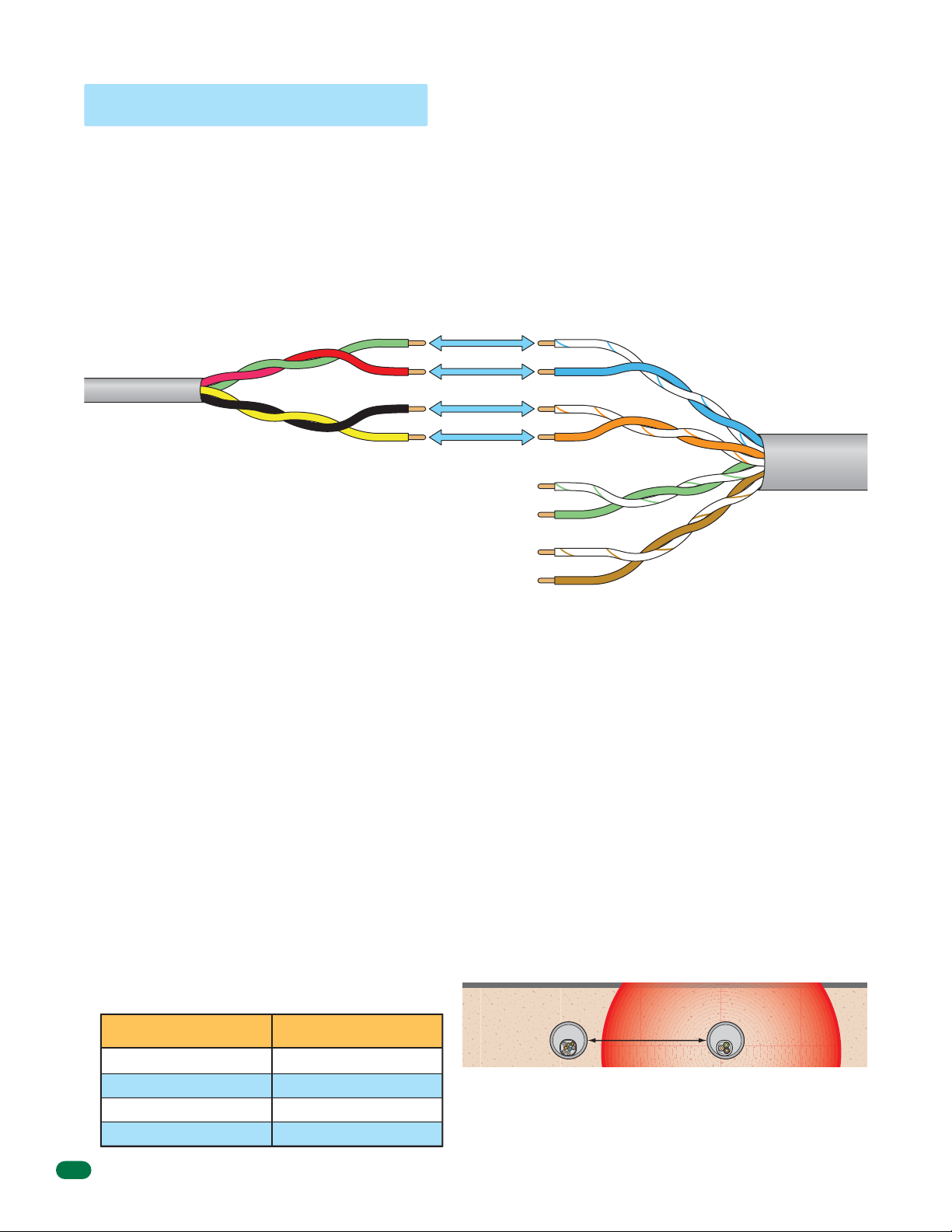
In most residential homes, the phone cable contains four wires; green, red, black, yellow. The green and red are twisted to make
one pair and the black and yellow are twisted to make another pair (This allowed for the addition of a second phone line since
telephones use only two wires). Most phone lines installed in the U.S. in the second half of the 20th Century have this type of
wire. This type of wire is now obsolete. All new telephone projects are using Cat5 wire. If you have Cat5 wiring in your home,
the conversion is simple:
Wire
Conversion
1st Line
2nd Line
Four Conductor
Wire
Older Residential
Homes
Green
Red
Black
Yellow
The convention for Cat5 wire is as follows:
• Colored pairs match; e.g., WHITE/blue mark (Tip +) wire goes
with BLUE/white mark (Ring -) wire for one phone line, etc.
• The pairs are used in the order pictured: for the first line, you
use BLUE, for the second line you use ORANGE, etc.
• An easy way to remember this is that the colors run from the
sky to the earth. BLUE sky comes first; ORANGE sunset second;
GREEN grass third; BROWN earth last.
3rd Line
4th Line
Tip (+)
Ring (-)
(+) Tip
(-) Ring
(+) Tip
(-) Ring
(+) Tip
(-) Ring
Blue Pair
Orange Pair
Green Pair
Brown Pair
Cat5 Wire
Modern Residential
Homes
“Tip” and “Ring” Definition. Common terms in the telephone service industry referring to the two wires or sides of
an ordinary telephone line. Tip is the ground side (positive) and Ring is the battery (negative) side of a phone circuit. The
ground side is common with the central office of the telephone company (telco); the battery side carries -48 volts of DC voltage
when in an “Idle” or “On Hook” state.
Phone Line Polarity. Tip and ring reversal is mostly immaterial, except for special circuits including DID (Direct Inward
Dialing) trunks, T-1 lines, and ground start lines where the field side (“terminal”) equipment (a company's PBX switch, for
example) can only function correctly with correct tip and ring polarity.
Wire Type. It is extremely important to use the correct type of wire in telephone applications. Since the 1812 requires
phone lines to be run outdoors or in an underground environment, we recommend that you use only wire that is rated for
direct underground burial. For example, use Cat5e Gel Filled (flooded) UV Resistant Direct Burial Cable run in conduit for
your 1812 phone line requirements. Do not use thinly insulated brown-jacketed telephone wire (the type found in the walls of a
house) for outdoor or underground phone line wiring. Using improper wire can cause noise and hum on the phone line. Be
sure that phone wire pairs are twisted.
Wire Size and Distance. Phone lines can be run up to 3600 feet, provided that the proper wire size is used.
Telephone Wire Run Table
Wire Size Max Distance
24 AWG
22 AWG
20 AWG
18 AWG
800 ft
1600 ft
2200 ft
3600 ft
Underground Cutaway
Telephone
Wire Conduit
Note: Do not run telephone wires and high voltage power
wires in the same conduit. Separate the high voltage
conduit and the telephone conduit by at least 18 inches to
prevent any electrical field interference that could occur.
Electrical field from power wires.
18” minimum
High Voltage
Power Wire
Conduit
12
1812-162-G-12-10
Page 15
1.4 Power Wiring
7 8 9
4 5 6
0
7 8 9
4 5 6
0
The 1812 Access Plus operates ONLY on 16.5 VAC. DO NOT power the 1812 with 24 volt AC power. Use the supplied power
transformer, 16 VAC, 20 VA (or U.L. listed equivalent) to power the telephone entry system. DO NOT power any other devices
(electric strikes, magnetic locks, etc.) from the 1812’s power transformer. See table below for wire run distances.
Power Interruption Note: The Time
Power Transformer Wire Run Table
Wire Size Max Distance
18 AWG
16 AWG
100 ft
200 ft
CAUTION
DO NOT power the 1812 from a 24-Volt
source (Such as a gate operator).
Damage will occur to the 1812 that is
NOT covered under DoorKing’s warranty.
Supplied Transformer
Output
16.5 VAC
20 VA
Polarity does
not matter.
Power Transformer Wires
(Not supplied)
and Date calendar chip (Section 2,
2.7.1) in the 1812 Access Plus will
keep time for approximately 48 hours
if power to the system is lost or
removed. If power is off longer than
this, the Time and Date will need to
be reprogrammed into the system.
All other specific programming that
has been done will remain intact after
power has been restored.
DoorKing offers a 12 volt .8 amp
hour gel cell battery that can
connect to the main terminals 9 and
10 to provide back-up power during
power interruptions.
(DoorKing P/N 1801-008)
1.5 Grounding and Surge Suppression
Proper Grounding and the use of surge suppressors can significantly reduce the chance of component failure because of static
charges or surges. To be effective, ground connections should be made with a minimum 12 AWG wire to a ground point within
10 feet of the device being protected. The ground point can be at an electrical panel, a metallic cold water pipe that runs in the
earth or a grounding rod driven at least 10 feet into the soil. A gooseneck mounting post anchored in concrete does NOT make
a good ground.
Some Acceptable Ground Sources
IMPORTANT: Ground wire shown without
safety protection for clarity. Make sure
Electrical
Panel
Ground to existing electrical system.
Ground
Wire
Ground to metallic cold water pipe.
ground wire is protected from being
touched or electrical shock could occur!
Ground
Wire
Grounding rod 10 feet in soil.
Telephone Line Surge Suppressor
It is highly recommended that telephone line surge
suppressor (DoorKing P/N 1877-010) be installed
to help protect the system from phone line power
surges. Surge suppressor must be positioned 3 ft
or less from the ground source, 12 AWG min.
Low Voltage Surge Suppressor
It is highly recommended that a low voltage surge
suppressor (DoorKing P/N 1878-010) be installed to
help protect the telephone entry system from power
surges. Surge suppressor must be positioned 3 ft or
less from the ground source, 12 AWG min.
1812-162-G-12-10
Phone Company
Transformer
1877-010
Surge Suppressor within
Surge Suppressor within
PHONE LINE
3 ft of ground source.
1878-010
POWER LINE
3 ft of ground source.
7
1812
1812
13
Page 16
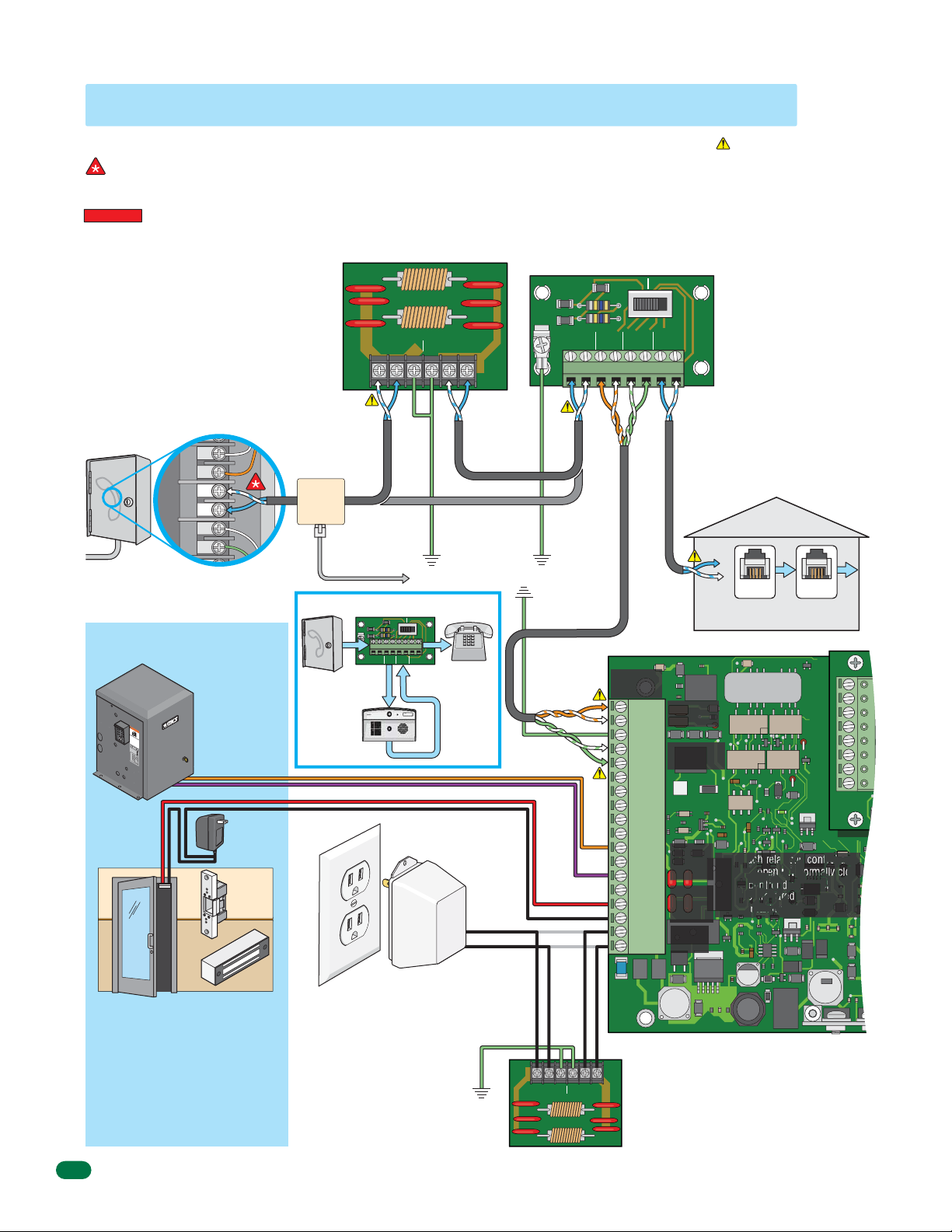
1.6 Wire One 1812 to a Telco Line - Telephone Mode
J1
7 8 9
4 5 6
0
Connect to Incoming Telephone
Company’s Phone Line
Locate the telephone company demarcation device.
IMPORTANT Identify the wires that connect to the
homeowner’s telephone. Disconnect these 2 wires from
the demarcation device and connect them to terminals
#7 and #8 HOME on the by-pass board.
Connect a new twisted-pair telephone wire to the
telephone company demarcation device where the 2
wires were just removed from. Connect the other end of
the new twisted-pair wire to CENTRAL OFFICE terminals
#1 and #2 on the by-pass board (Unless using a surge
suppressor, then wire to surge board first).
Place the by-pass switch in the “By-Pass” position until
the 1812 installation is complete. Test the homeowner’s
telephone. It should have a dial tone while the switch is
in the “By-Pass” position. See page 11.
Telephone
Company
Demarcation
Point
Central Office (C.O.)
Demarcation Device
Locate Homeowner’s
Phone Line Inside Device
Home #11
Phone at
Tip
Ring
Home #12
Phone at
Tip
Ring
Home #13
Phone at
Tip
Ring
TIP (+): White/blue mark
“Existing”
Alarm
System
Location
RJ31x
Phone Jack
installed
Before 1812
System
RING (-): Blue/white mark
Single 1812 Wiring Configuration
Access Control Devices
“Normally Open”
WA
RNIN
G
MOV
S
I
NG
E
RI
GA
O
US
O
T
p
E
INJ
er
at
C
an
e
A
d
gat
URY
f
N
r
e
e o
e
C
of
n
A
l
D
p
y
O
US
o
eop
w
R
no
h
e
o
l
E
t
DE
e an
n
r
al
op
g
l
a
o
d
A
t
er
w
e
o
a
ch
at
T
bst
r
e
H
e
g
i
D
a i
l
r
dr
at
uct
o
s i
e
e
n
n
.
i
o
n
o
p
t
t
n
at
o
s
st
s.
i
g
h
pl
a
h
w
n
ay
t
d
h
i
i
i
n
l
n
e
g
gat
R
ga
a
ea
t
t
e
e
e
d
a
p
o
i
s
r
at
e
w
m
a
h
n
o
or
e
vi
r
’
w
n
s
g
m
al
.
k t
a
n
h
u
r
a
o
l
a
ug
n
h
d
saf
et
y i
n
st
r
u
ct
i
o
n
s
.
C
O
NF
O
A
R
N
M
S
I
S
/
U
T
L
O
-
3
C
C
2
A
E
5
N
R
/
T
C
I
F
S
I
A
E
D
C
VEH
T
2
2
O
.
2
I
N
CU
O.
5
33
C
LAR
2
82
L
4
A
7
S
G
S
A
T
E O
M
O
D
P
E
ER
L
AT
S
O
E
H
RI
R
P
A
L
V
O
L
T
S
A
M
P
S
M
A
P
X
H
G
A
A
S
T
E
E
L
O
A
D
6
D
o
0
o
H
r
K
z
i
n
g
,
I
n
c
.
,
I
n
g
l
e
w
o
o
d
,
C
A
Pedestrian
Gate/Door
Vehicular
Gate Operator
Use minimum 18
AWG wire for runs
up to 100 feet.
16 AWG wire for
runs up to 200 feet.
(Term. 11 and 13)
Separate UL
Listed Power
Transformer
Electric
Strike
Maglock
Phone
Company
Phone Mode
Phone Line Surge Suppressor
DoorKing Surge Suppressor
P/N 1877-010 (or equivalent) is
optional but highly recommended.
For best protection, surge suppressor
ground wire MUST be 3-ft. or less in
length. Use minimum 12 AWG wire.
Refer to instruction sheet included
with surge board for complete
information.
1877-010
PHONE LINE
INPUT
TIP RING GND GND
Recommended
Cat5e
To “Existing”
Alarm Control Panel
EARTH
GND
1
2345678
CENTRAL
PHONEINPHONE
OFFICE
Phone In
Phone In
7
Phone Out
Ground 12 AWG
ENTRY BY-PASS
OUT
HOME
Phone
Out
OUTPUT
TIP RING
Min. Within 3 ft
of Surge Board
Cat5e Without Surge Board
Be sure to properly
ground ALL boards.
See previous page
for acceptable
grounding sources.
SW1
1875-010
Homeowner’s
Phone
LAN/Cordless
Supplied Transformer
Polarity does not matter.
t
utpu
O
16.5 VAC
20 VA
Telephone
Line
For complete
information,
see page 12.
Cat5e
The By-Pass board is NOT optional and
must be installed as part of the 1812
“Telephone Mode” system.
See page 11 for complete information.
Single 1812:
PHONE IN #3 connects to Main Term #1.
PHONE IN #4 connects to Main Term #2.
PHONE OUT #5 connects to Main Term #5.
PHONE OUT #6 connects to Main Term #4.
ENTRY BY-PASS
SW1
EARTH
GND
1
CENTRAL
OFFICE
Ground
12 AWG Min.
Ground
12 AWG Min.
2345678
PHONEINPHONE
OUT
TIP
TIP
Pair
TIP
RING
Green
Pair
RING
Orange
Cat5e
1875-010
HOME
RING
TIP
RING
Cat5e
Green Wire (+)
Main
Terminal
By-Pass Board
Orange Pair
Green Pair
J1
1 RING
2 TIP
3 GND
4 TIP
5
6
7
8
9
10
11 N.O.
12 N.C.
13 Com
14 N.O.
15 N.C.
16
17
18
RING
Com
16.5
VAC
Phone In
(1-2)
Phone Out
(4-5)
1970-010
Relay 1
(11-13)
Relay 2
(14-16)
Power
(17-18)
Check Polarity of
Telephone Line
Check for polarity on the
incoming telephone line to each
board and maintain polarity
throughout the telephone line.
One potential problem checked
when a malfunction occurs in a
telephone entry system is to
see if the telephone line has
been wired to each board with
the correct polarity.
Test Example: By-pass board’s
CENTRAL OFFICE terminals #1
and #2. Terminal #2 must be
positive (Tip +) with respect to
terminal #1 (Ring -). Set a VOM
meter to measure DC volts.
Place the positive lead on
terminal #2 and the negative
lead on terminal #1. If the
meter shows a positive voltage
- OK. If the meter shows a
negative voltage (needle moves
off scale to the left), reverse the
wires on terminals #1 and #2.
Homeowner’s
LAN/Cordless Phones
Older Lines
Red Wire (-)
RING
TIP
Older Lines
Phone
Jack
Note: Each relay can control a
normally open OR normally close
access control device. Relay
contacts are rated for 3 amps @
30 VAC maximum.
Phone
Jack
J4
1
2
3
4
5
6
7
8
“Normally Close” with Maglock
“Normally Open” with Electric Strike
(Terminal 15 and 16)
Magnetic locks or electric strikes must be
powered from a separate UL Listed power
transformer. DO NOT power strikes or magnetic
locks from the 1812 power transformer. Use
minimum 18 AWG wire for runs up to 100 feet;
16 AWG wire for runs up to 200 feet. It is
recommended to keep power wire runs as short
as possible.
14
(Terminal 14 and 16)
The 1812 Access Plus operates ONLY
on 16.5 VAC. DO NOT power the 1812
with 24 Volt transformer or source
voltage. Use the supplied power
transformer, 16.5 VAC, 20 VA (or UL
listed equivalent) to power the
telephone entry system. DO NOT power
any other devices (electric strikes,
magnetic locks, additional 1812s etc.)
from the 1812’s power transformer.
See previous page for wire size and
run distances.
Ground
12 AWG Min.
Within 3 ft
of Surge Board
Recommended
1878-010
Recommended
OUTOUT
OUTPUT
LOW VOLTAGE LINE
INPUT
Low Voltage Surge Suppressor
DoorKing Surge Suppressor P/N 1878-010 (or
ININGNDGND
equivalent) is optional but highly recommended.
For best protection, surge suppressor ground wire
MUST be 3-ft. or less in length. Use minimum 12 AWG
wire. Refer to instruction sheet included with surge
board for complete information.
1812-162-G-12-10
Page 17
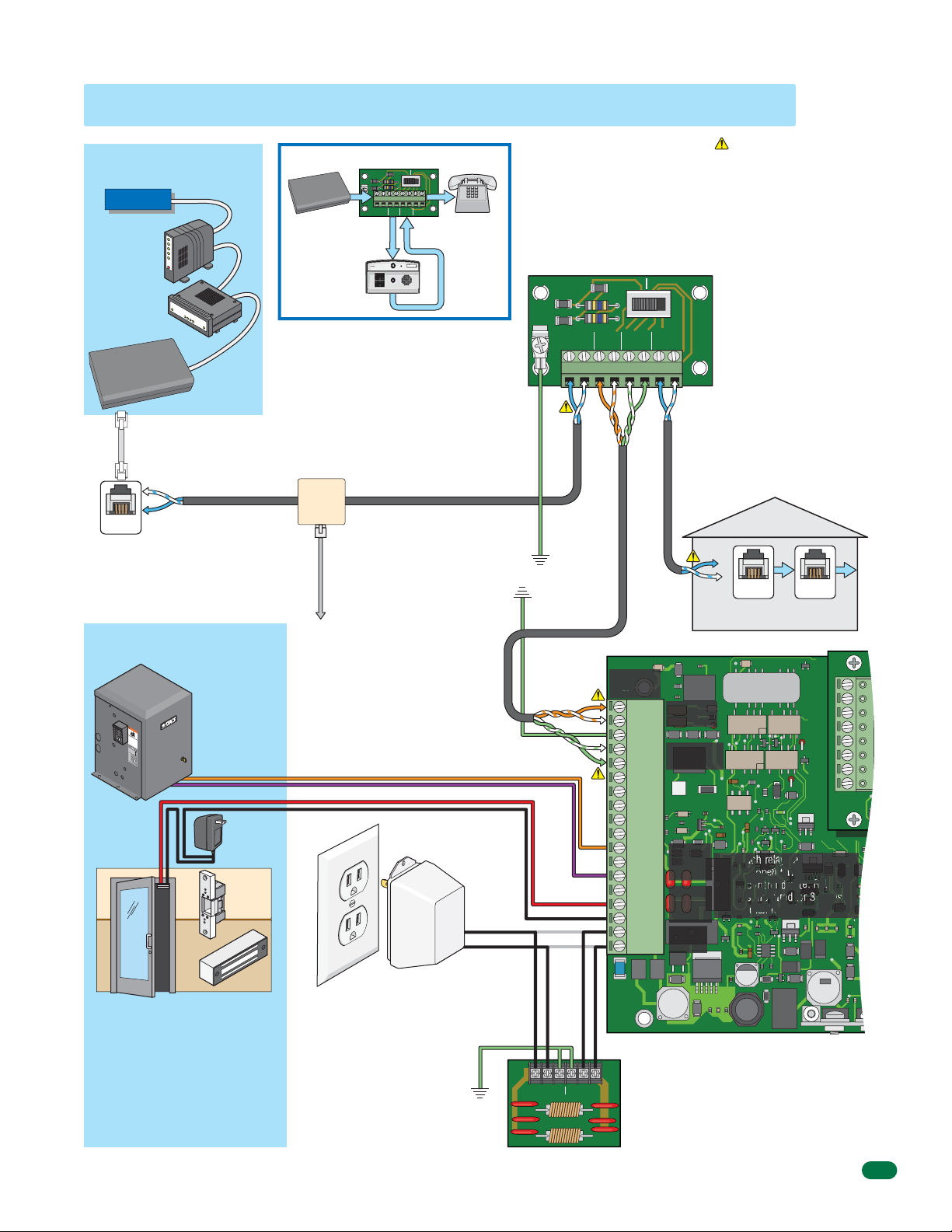
1.7 Wire One 1812 to the Internet - Telephone Mode
J1
7 8 9
4 5 6
0
Typical “Existing”
Internet Source
Internet
Internet
DSL/Cable
Modem
Router
Fiber / VolP
Device
RJ-11
Phone
Connector
TIP (+): White/blue mark
RING (-): Blue/white mark
Phone
Jack
Access Control Devices
“Normally Open”
Vehicular
Gate Operator
Use minimum 18
WA
R
N
I
NG
MOV
S
I
NG
E
RIOUS
GA
O
T
p
E
I
er
NJ
at
C
a
n
e
A
d
g
URY
N
f
at
r
ee
e
on
C
o
A
f
l
D
p
y
OR DE
US
w
o
eo
n
h
pl
o
en
o
E
t
e an
r
a
o
g
l
l
per
at
o
d
A
w
e
ob
ch
at
T
a
r
e
H
s
e
g
i
D
t
l
a
r
dr
i
at
o n
uct
s
e
e.
n
i
i
o
n
o
t
p
t
s
n
a
o
s
t
s
i
h
g
t
pl
.
an
h
w
ay
t
d
hi
i
i
n
l
n g
e g
g
R
at
at
at
ead
e
e
e i
ar
pat
s m
ow
ea
h o
ner
o
vi
r
’
w
n
s
g
m
a
.
l
k t
a
nu
h
r
a
ou
l
a
g
nd
h
s
af
et
y
i
ns
t
r
u
ct
i
o
n
s
.
C
ON
F
ORM
A
NS
I
S
/
UL
T
O
-
3
C
C
2
A
E
5
N/
RT
C
I
F
S
I
A
E
D
C
VE
2
T
2
O
.
H
2
I
N
C
O
U
5
.
3
C
3
LA
2
8
L
2
4
A
7
R
S
G
S
A
TE
M
O
O
DE
PE
L
R
AT
S
OR
E
HP
RI
A
L
V
OL
T
S
A
M
P
S
M
A
P
X
H
G
A
A
S
T
E
E
L
O
A
D
6
D
o
0
o
H
r
K
z
i
n
g
,
I
n
c
.
,
I
n
g
l
e
w
o
o
d
,
C
A
Pedestrian
Gate/Door
AWG wire for runs
up to 100 feet.
16 AWG wire for
runs up to 200 feet.
(Term. 11 and 13)
Separate UL
Listed Power
Transformer
Electric
Strike
Maglock
Single 1812 Wiring Configuration
Fiber / VolP
Device
Internet
EARTH
GND
1
CENTRAL
Phone In
ENTRY BY-PASS
2345678
PHONEINPHONE
OFFICE
SW1
1875-010
HOME
OUT
Phone
Out
Phone In
Phone Mode
7
Phone Out
“Existing” Alarm
System Location
RJ31x
Phone Jack
installed
Before 1812
System
To “Existing”
Alarm Control Panel
Telephone Line (Cat5e)
For complete information,
Cat5e
Supplied Transformer
Polarity does not matter.
Homeowner’s
Phone
LAN/Cordless
see page 12.
Be sure to properly ground
ALL boards. See page 13
for acceptable grounding
utput
O
5 VAC
16.
20 VA
sources.
The By-Pass board is NOT optional and
must be installed as part of the 1812
“Telephone Mode” system.
See page 11 for complete information.
Single 1812:
PHONE IN #3 connects to Main Term #1.
PHONE IN #4 connects to Main Term #2.
PHONE OUT #5 connects to Main Term #5.
PHONE OUT #6 connects to Main Term #4.
ENTRY BY-PASS
SW1
EARTH
GND
1
CENTRAL
OFFICE
Ground
12 AWG Min.
Ground
12 AWG Min.
2345678
PHONEINPHONE
OUT
TIP
TIP
Pair
TIP
RING
Green
Pair
RING
Orange
Cat5e
1875-010
HOME
RING
TIP
RING
Cat5e
Green Wire (+)
Main
Terminal
By-Pass Board
Orange Pair
Green Pair
J1
1 RING
2 TIP
3 GND
4 TIP
5
6
7
8
9
10
11 N.O.
12 N.C.
13 Com
14 N.O.
15 N.C.
16
17
18
RING
Com
16.5
VAC
Phone In
(1-2)
Phone Out
(4-5)
1970-010
Relay 1
(11-13)
Relay 2
(14-16)
Power
(17-18)
Check Polarity of
Telephone Line
Check for polarity on the
incoming telephone line to each
board and maintain polarity
throughout the telephone line.
One potential problem checked
when a malfunction occurs in a
telephone entry system is to
see if the telephone line has
been wired to each board with
the correct polarity.
Test Example: By-pass board’s
CENTRAL OFFICE terminals #1
and #2. Terminal #2 must be
positive (Tip +) with respect to
terminal #1 (Ring -). Set a VOM
meter to measure DC volts.
Place the positive lead on
terminal #2 and the negative
lead on terminal #1. If the
meter shows a positive voltage
- OK. If the meter shows a
negative voltage (needle moves
off scale to the left), reverse the
wires on terminals #1 and #2.
Homeowner’s
LAN/Cordless Phones
Older Lines
Red Wire (-)
RING
TIP
Older Lines
Phone
Jack
Note: Each relay can control a
normally open OR normally close
access control device. Relay
contacts are rated for 3 amps @
30 VAC maximum.
Phone
Jack
J4
1
2
3
4
5
6
7
8
“Normally Close” with Maglock
“Normally Open” with Electric Strike
(Terminal 15 and 16)
Magnetic locks or electric strikes must be
powered from a separate UL Listed power
transformer. DO NOT power strikes or magnetic
locks from the 1812 power transformer. Use
minimum 18 AWG wire for runs up to 100 feet;
16 AWG wire for runs up to 200 feet. It is
recommended to keep power wire runs as short
as possible.
1812-162-G-12-10
(Terminal 14 and 16)
The 1812 Access Plus operates ONLY
on 16.5 VAC. DO NOT power the 1812
with 24 Volt transformer or source
voltage. Use the supplied power
transformer, 16.5 VAC, 20 VA (or UL
listed equivalent) to power the
telephone entry system. DO NOT power
any other devices (electric strikes,
magnetic locks, additional 1812s etc.)
from the 1812’s power transformer.
See page 13 for wire size and run
distances.
Ground
12 AWG Min.
Within 3 ft
of Surge Board
Recommended
1878-010
Recommended
OUTOUT
OUTPUT
LOW VOLTAGE LINE
INPUT
Low Voltage Surge Suppressor
DoorKing Surge Suppressor P/N 1878-010 (or
ININGNDGND
equivalent) is optional but highly recommended.
For best protection, surge suppressor ground wire
MUST be 3-ft. or less in length. Use minimum 12 AWG
wire. Refer to instruction sheet included with surge
board for complete information.
15
Page 18
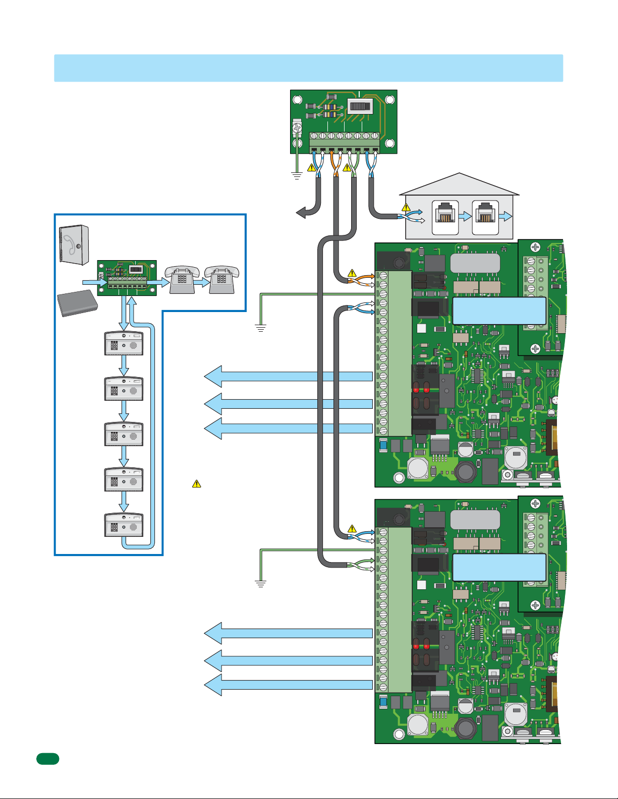
1.8 Wire Multiple 1812s: Telco/Internet - Telephone Mode
J1
7 8 9
4 5 6
0
7 8 9
4 5 6
0
7 8 9
4 5 6
0
7 8 9
4 5 6
0
7 8 9
4 5 6
0
Use the previous 2 page’s wiring diagrams and
information to wire multiple 1812s except for
the By-Pass board’s “PHONE IN” and “PHONE
OUT” terminal connections. Up to five (5) 1812s
may be wired in series to the By-Pass board
using the method shown on this page: 1st
1812’s PHONE OUT to 2nd 1812’s PHONE IN;
2nd 1812’s PHONE OUT to 3rd 1812’s PHONE
IN, etc. Connect the last 1812’s PHONE OUT
back to By-Pass board’s PHONE OUT.
Maximum 1812 Wiring Configuration
ENTRY BY-PASS
2345678
PHONEINPHONE
HOME
OUT
SW1
1875-010
Homeowner’s Phones
(LAN/Cordless)
See previous
2 pages for
wiring and
information.
See previous
2 pages for
wiring and
information.
Be sure to properly ground ALL
1812s. See page 13 for
acceptable grounding sources.
Relay 1 to Access Control Device
Relay 2 to Access Control Device
To 16.5 VAC Supplied Transformer
Check Polarity of Telephone Line
See previous 2 pages for information.
Be sure to properly ground ALL
1812s. See page 13 for
acceptable grounding sources.
Relay 1 to Access Control Device
Relay 2 to Access Control Device
To 16.5 VAC Supplied Transformer
Phone
Company
Fiber / VolP
1st 1812
Phone Mode
(E.g.: 5 Rings)
2nd 1812
Phone Mode
(E.g.: 6 Rings)
3rd 1812
Phone Mode
(E.g.: 6 Rings)
4th 1812
Phone Mode
(E.g.: 6 Rings)
5th 1812
Phone Mode
(E.g.: 6 Rings)
Note: Each 1812 must be
programmed for MULTIPLE
OR
Device
Internet
EARTH
GND
1
CENTRAL
OFFICE
Phone In Phone Out
Phone In
7
Phone Out
Phone In
Phone Out
Phone In
Phone Out
Phone In
Phone Out
Phone In
Phone Out
SYSTEMS, have a unique
ATTENTION NUMBER (See
2.4.2 and 2.4.3) and have a
unique MASTER CODE (See
2.1).
Note: The 1812 that is
connected directly to the
homeowner’s phones (1st
1812) must have its
“Number of Rings”
programming set for 1 less
than the other 1812s wired
in series (See 2.4.9).
Ground
12 AWG Min.
See previous 2
pages for more
information
about Telco OR
Internet wiring.
Ground 12 AWG Min.
Ground 12 AWG Min.
EARTH
GND
1
CENTRAL
OFFICE
RING
ENTRY BY-PASS
2345678
PHONEINPHONE
TIP
TIP
RING
Cat5eCat5e
OUT
TIP
Cat5e
SW1
HOME
RING
RING
By-Pass Board
The By-Pass board is NOT optional and must be
installed as part of multiple 1812s “Telephone Mode”
1875-010
system.
See page 11 for complete information.
Multiple 1812s:
PHONE IN #3 connects to 1st 1812 Main Term #1.
TIP
PHONE IN #4 connects to 1st 1812 Main Term #2.
PHONE OUT #5 connects to Last 1812 Main Term #5.
PHONE OUT #6 connects to Last 1812 Main Term #4.
Homeowner’s
LAN/Cordless Phones
Older Lines
Red Wire (-)
RING
TIP
Older Lines
Green Wire (+)
Phone
Jack
Phone
Jack
Main
Terminal
J1
1 RING
Phone In
2 TIP
(1-2)
3 GND
4 TIP
Phone Out
(4-5)
RING
5
6
1st 1812
7
1970-010
8
9
10
11 N.O.
Relay 1
12 N.C.
13 Com
14 N.O.
15 N.C.
Relay 2
16
Com
17
16.5
Power
VAC
18
Main
Terminal
J1
J1
1 RING
Phone In
RING
Com
16.5
VAC
(1-2)
Phone Out
(4-5)
1970-010
Relay 1
Relay 2
Power
Last 1812
2 TIP
3 GND
4 TIP
5
6
7
8
9
10
11 N.O.
12 N.C.
13 Com
14 N.O.
15 N.C.
16
17
18
J4
1
2
3
4
5
6
7
8
J4
1
2
3
4
5
6
7
8
16
1812-162-G-12-10
Page 19

1.9 Wire One 1812 - Intercom Mode
J1
7 8 9
4 5 6
0
Connect to Homeowner’s Telephone
When connecting directly to a single telephone or an
un-used C.O. port on a PBX or KSU system, use the
PHONE OUT terminals only in the 1812. It must be
programmed for INTERCOM mode using this
configuration.
When the 1812 is programmed for intercom mode, it
provides the constant source of DC voltage necessary
for communication. The intercom mode also
disconnects the “PHONE IN” terminals (1 and 2)
since they are not used.
Be sure that the 1812 is programmed in the intercom
mode.
Single 1812 Wiring Configuration
7
Phone Out
Intercom Mode
Homeowner’s Phone
LAN/Cordless
Phone
Jack
Cordless
Option
Cordless Phone Base Station
Older Lines
Red Wire (-)
RING
TIP
Older Lines
Green Wire (+)
RJ-11
Phone
Connector
TIP (+):
White/blue mark
RING (-):
Blue/white mark
Telephone Line
For complete information, see page 12.
Homeowner’s Phone
LAN/Cordless
Access Control Devices
“Normally Open”
Vehicular
Gate Operator
Use minimum 18
WA
R
NI
N
G
MOV
S
I
NG
E
RIOUS
GA
O
T
per
E
INJ
a
C
an
t
e g
A
d
URY
f
N
at
r
ee
e
C
o
of
nl
A
OR
D
p
y
US
o
eo
w
n
h
pl
o
en
o
E
t
DE
e
r
al
a
op
ga
l
n
o
d
A
t
er
w
e
o
a
T
ar
c
b
t
h
e
H
s
ea i
i
D
t
l
gat
r
d
o
u
r
s i
n
c
e
e.
t
n
i
ot
n
o
t
p
si
ns
at
o
s
h
g
t
pl
.
an
w
h
ay
t
d
hi
i
i
n
l
n
e
gat
g
R
ga
at
ead
t
e
e
e
p
a
i
s
ow
r
a
ea
t
m
h
n
ov
or
e
r
i
’
n
s m
w
g.
al
k
an
t
hr
ua
ou
l
a
g
nd
h
s
a
f
et
y i
ns
t
r
u
ct
i
o
n
s
.
C
O
NF
ORM
A
N
S
I
S
/
UL
T
O
-
3
C
C
2
A
E
5
N/
RT
C
I
F
S
I
A
E
D
C
V
2
T
2
EH
O
.
2
I
N
C
O.
U
5
3
C
3
L
2
8
L
A
2
4
A
7
R
S
S
G
A
T
E
M
O
O
DE
P
E
L
R
AT
S
O
E
HP
R
R
I
A
L
V
OLT
S
A
M
P
S
M
A
P
X
H
G
A
A
S
T
E
E
L
O
A
D
6
D
o
0
o
H
r
K
z
i
n
g
,
I
n
c
.
,
I
n
g
l
e
w
o
o
d
,
C
A
Pedestrian
Gate/Door
“Normally Close” with Maglock
“Normally Open” with Electric Strike
(Terminal 15 and 16)
Magnetic locks or electric strikes must be
powered from a separate UL Listed power
transformer. DO NOT power strikes or
magnetic locks from the 1812 power
transformer. Use minimum 18 AWG wire for
runs up to 100 feet; 16 AWG wire for runs
up to 200 feet. It is recommended to keep
power wire runs as short as possible.
(Terminal 14 and 16)
AWG wire for runs
up to 100 feet.
16 AWG wire for
runs up to 200 feet.
(Term. 11 and 13)
Separate UL
Listed Power
Transformer
Electric
Strike
Maglock
Remote phones throughout house.
Ground 12 AWG Min.
Be sure to properly ground the 1812. See
page 13 for acceptable grounding sources.
utput
O
5 VAC
16.
20 VA
Supplied Transformer
Polarity does not matter.
The 1812 Access Plus operates ONLY
on 16.5 VAC. DO NOT power the 1812
with 24 Volt transformer or source
voltage. Use the supplied power
transformer, 16.5 VAC, 20 VA (or UL
listed equivalent) to power the
telephone entry system. DO NOT power
any other devices (electric strikes,
magnetic locks, additional 1812s etc.)
from the 1812’s power transformer.
See page 13 for wire size and run
distances.
Be sure to properly ground the
surge suppressor. See page 13 for
acceptable grounding sources.
Cat5e
Recommended
1878-010
Recommended
OUTOUT
OUTPUT
LOW VOLTAGE LINE
INPUT
Main
Terminal
J1
1 RING
Not
Used
2 TIP
Phone In
3 GND
4 TIP
Phone Out
(4-5)
RING
5
6
7
1970-010
8
9
10
11 N.O.
Relay 1
12 N.C.
13 Com
14 N.O.
15 N.C.
Com
16
17
16.5
VAC
18
Note: Each relay can control a
(11-13)
normally open OR normally close
access control device. Relay
contacts are rated for 3 amps @
Relay 2
30 VAC maximum.
(14-16)
Power
(17-18)
Low Voltage Surge Suppressor
DoorKing Surge Suppressor P/N 1878-010 (or
ININGNDGND
equivalent) is optional but highly recommended.
For best protection, surge suppressor ground wire
MUST be 3-ft. or less in length. Use minimum 12 AWG
wire. Refer to instruction sheet included with surge
board for complete information.
J4
1
2
3
4
5
6
7
8
1812-162-G-12-10
17
Page 20

1.10 Wire Multiple 1812s - Intercom Mode
J1
J
7 8 9
4 5 6
0
7 8 9
4 5 6
0
7 8 9
4 5 6
0
7 8 9
4 5 6
0
7 8 9
4 5 6
0
Up to five (5) 1812s may be
wired in series using the method
shown: 1st 1812’s PHONE IN to
2nd 1812’s PHONE OUT; 2nd
1812’s PHONE IN to 3rd 1812’s
PHONE OUT, etc.
Each 1812 must have a unique
ATTENTION NUMBER (See 2.4.3)
and a unique MASTER CODE (See
2.1).
The 1812 that is the furthest away
from the phone or PBX / KSU
system must be programmed for
INTERCOM MODE. All other 1812
units in the series are
programmed for TELEPHONE
MODE (See 2.4.1).
Maximum 1812 Wiring
Configuration
Phone In
1st 1812
Phone Mode
Homeowner’s Phone
LAN/Cordless
2nd 1812
Phone Mode
Phone Out
Phone In
Phone Out
7
See previous
information
1 2 3
transformer.
Homeowner’s Phone
LAN/Cordless
Phone
Cordless
Option
Cordless Phone Base Station
Remote phones throughout house.
Be sure to properly ground ALL
1812s. See page 13 for
acceptable grounding sources.
page for
wiring and
on relays
and power
Relay 1 to Access Control Device
Relay 2 to Access Control Device
To 16.5 VAC Supplied Transformer
Older Lines
Red Wire (-)
RING
TIP
Older Lines
Green Wire (+)
Jack
RJ-11
Phone
Connector
Ground 12 AWG Min.
Connect to Homeowner’s
Telephone
Connect the 1st 1812’s PHONE OUT
terminals directly to homeowner’s
phone or an un-used C.O. port on a
PBX or KSU system.
TIP (+):
White/blue mark
RING (-):
Blue/white mark
Telephone Line
For complete information,
see page 12.
Cat5e
Main
Terminal
J1
1 RING
2 TIP
3 GND
4 TIP
RING
5
6
7
8
Cat5e
9
10
11 N.O.
12 N.C.
13 Com
14 N.O.
15 N.C.
16
Com
17
16.5
VAC
18
Check Polarity of Telephone Line
Check for polarity on the incoming telephone line to
each 1812 board and maintain polarity throughout
the telephone line to the homeowner’s phone. One
potential problem checked when a malfunction
occurs in a telephone entry system is to see if the
telephone line has been wired to each board with
the correct polarity.
Test Example: 1st 1812 board’s PHONE IN
terminals #1 and #2. Terminal #2 must be positive
(Tip +) with respect to terminal #1 (Ring -). Set a
VOM meter to measure DC volts. Place the positive
lead on terminal #2 and the negative lead on
terminal #1. If the meter shows a positive voltage
- OK. If the meter shows a negative voltage (needle
moves off scale to the left), reverse the wires on
terminals #1 and #2.
J4
1
Phone In
(1-2)
Phone Out
(4-5)
1st 1812
2
3
4
5
6
7
8
1970-010
Relay 1
Note: Each relay can control a
normally open OR normally close
access control device.
Relay 2
Power
18
3rd 1812
Phone Mode
4th 1812
Phone Mode
5th 1812
INTERCOM MODE
Phone In
Phone Out
Phone In
Phone Out
Phone Out
Be sure to properly ground ALL
1812s. See page 13 for
acceptable grounding sources.
See previous
Relay 1 to Access Control Device
page for
wiring and
information
on relays
Relay 2 to Access Control Device
and power
transformer.
To 16.5 VAC Supplied Transformer
When multiple 1812 systems are
connected together, maintain
common polarity on ALL phone lines.
Ground 12 AWG Min.
To the next 1812’s PHONE OUT
terminals 4 and 5 wired in the series,
if desired.
Main
Terminal
J1
1
1 RING
2 TIP
3 GND
4 TIP
RING
5
6
7
8
9
10
11 N.O.
12 N.C.
13 Com
14 N.O.
15 N.C.
16
Com
17
16.5
VAC
18
Phone In
(1-2)
Phone Out
(4-5)
1970-010
Relay 1
Relay 2
Power
J4
1
2
3
4
5
6
2nd 1812
7
8
Note: Each relay can control a
normally open OR normally close
access control device.
1812-162-G-12-10
Page 21

1.11 Main Terminal Description
M
M
Phone In
(Twisted Pair)
Phone Out
(Twisted Pair)
Emergency
and/or Postal
Entry Switch
Back-Up
Battery Power
Relay 1
(Access Control Device)
Relay 2
(Access Control Device)
Input Power
(Transformer)
1. Phone In (Negative - Ring)
2. Phone In (Positive - Tip)
3. Ground (Required)
4. Phone Out (Positive - Tip)
5. Phone Out (Negative - Ring)
6. Not Used.
7. Switch Input Relay 1. A switch closure across terminals 7 & 9
will activate relay 1 for its programmed strike time.
8. Switch Input Relay 2. A switch closure across terminals 8 & 9
will activate relay 2 for its programmed strike time.
9. - 12 VDC Battery Negative. Also Common for terminals 7 & 8.
10. + 12 VDC Battery Positive.
11. Relay 1 Normally Open
12. Relay 1 Normally Closed
13. Relay 1 Common
WARNING
Maximum
input voltage to terminals
9 and 10 is 14.5 Volts DC.
14. Relay 2 Normally Open
15. Relay 2 Normally Closed
16. Relay 2 Common
17. 16.5 VAC Input Power
18. 16.5 VAC Input Power
1.12 Access Plus Interface Board
1970-010
J1
1
2
3
4
5
6
7
8
9
10
11
12
13
14
15
16
17
18
J4
1
2
3
4
5
6
7
8
The 1812 Access Plus interface board (1972-010) is piggybacked onto the main 1812 Plus circuit board (1970-010). The
interface board provides additional connections to the 1812 for keypads, card readers and/or RF receivers using RS-485
communication protocol.
The 1812 Access Plus can be programmed via a PC using a network or modem connection. An RJ-45 jack (Cat5) is provided on
the interface board for network connections.
1.12.1 8-Pin RS-485 Connector Description
Use the RS-485 terminals to add up to six (6) card readers, keypads and/or RF receivers to the 1812 Access Plus system. These
devices must be wired in a daisy-chain format with a maximum wire run distance of 4000 feet. We recommend that you use
Cat5e wire for all RS-485 wire runs.
DO NOT power RS-485 devices from the 1812. These devices must be supplied with their own power source. Refer to the
individual device wiring instructions for connection information and wiring guidelines for these products.
Be sure to set programming commands 09 (section 2.6.2) and 07 (section 2.6.3) when connecting RS-485 devices to the 1812
Access Plus system.
1970-010
J1
1
2
3
4
5
6
7
8
9
10
11
12
13
14
RS-485 DATA A (+)
RS-485 DATA B (-)
RS-485 Common
Terminals 4-8
are not used
with 1812
Access Plus
applications.
J4
1
2
3
4
BAD DNS
RS-485 RX
LAN DOWN
SW1
ON
MODEM / TCP ENB
MASTER
CODE
5
6
7
LAN CONNECTION
J1
8
RJ-45
Jack
(Cat5)
DATA TRANSMIT
PHONE LINE
IN USE
1972-010
J3
MIC VOL
KEYPAD
1812-162-G-12-10
19
Page 22

MASTER
M
CODE
J1
J3J3J3
J
0
109
7
6
5
4
3
1
RS-485 Daisy Chain Wiring
7
8
9
4
5
6
1 2
3
0
0
1513-010
1970-010
1970-01
Terminals 1 and 2
MUST be twisted.
J1
1
2
3
4
5
6
7
8
8
9
10
11
12
13
The wires connecting terminals 1 & 2 from
14
the 1812 Access Plus to terminals 8 & 7
15
on the DoorKing RS-485 boards MUST be
16
twisted. We recommend that you use
17
Cat5e cable for all the RS-485 connec-
18
tions (See page 12 for wire size and run
distances table). Use one twisted pair to
Cat5e
connect these terminals (terminal 1
connects to terminal 8; terminal 2
connects to terminal 7) and then one wire
from another twisted pair to connect the
common terminal (terminal 3 from the
1812 Access Plus to terminal 6 on the
RS-485 board).
RS-485
Keypad
If wiring will be
outdoors or under-
ground, use Cat5e
Gel Filled (flooded)
UV Resistant Direct
Burial Cable.
7
Device Address
Set to 003
MASTER CODE
SW1
When 6 RS-485 wires are
connected to terminal,
1513-010
then termination switch
MUST be OFF.
678 10954321
-
+
Com
Any RS-485 Keypad, Cardreader and
MicroPlus RF Receiver sequence
allowed. Maximum distance from end
to end is 4000 feet in a Daisy Chain
format as shown, see next page for
different RS-485 wiring configurations.
J4
+
-
Com
RS-485
Cardreader
13
ON
OFF
SW2
RS-485 DATA A (+)
1
RS-485 DATA B (-)
2
RS-485 Common
3
4
5
6
LAN CONNECTION
7
8
Device Address
Terminals 7 and 8
MUST be twisted.
Cat5e
RS-485 RX
BAD DNS
LAN DOWN
DATA TRANSMIT
J1
RJ-45
Jack
(Cat5)
KEYPAD
SW4 SW2 SW3
ON
BOARD ADDRESS
8
7
9
6
0
5
1
4
2
3
Set to 004
8
7
9
6
0
5
1
4
2
3
When 6 RS-485 wires are
connected to terminal,
354-01
then termination switch
2354-010
MUST be OFF.
SW1
678 10954321
-
+
Com
Do Not power RS-485 devices from the 1812.
RS-485 devices must be powered from their
own power source. Refer to the individual device
wiring instructions for connection information
and wiring guidelines for these products.
ON
SW1
MODEM / TCP ENB
PHONE LINE
IN USE
1972-010
J3
RS-485
MicroPlus
RF Receiver
Device Address
Set to 005
OFF
Setting the device address switches
are different for each RS-485 device.
Refer to the individual RS-485
instruction sheet to set the addresses
for these products and see the next
page for more information about
address restrictions.
1970-010
J2
When 3 RS-485 wires are
connected to terminal, then
termination switch MUST
be ON (End of chain).
8053-010
SW4 SW5SW2 SW3
ON
0
1
9
9
2
8
8
3
7
7
4
6
6
5
Terminals 7 and 8
MUST be twisted.
Cat5e
0
5
67854321
Com
1
MASTER
CODE
MIC VOL
N
O
5
2
1
W
3
0
S
4
9
5
8
7
6
2
1
3
0
3
0
1
W
4
9
-0
3
5
8
5
7
0
6
8
N
O
W2 S
S
4
W
S
SPEAKER
VOL
1112345678910
ON
2
3
4
-
+
20
1812-162-G-12-10
Page 23

RS-485 Configurations
7 8 9
4 5 6
1 2 3
0
7 8 9
4 5 6
1 2 3
0
7 8 9
4 5 6
1 2 3
0
7 8 9
4 5 6
1 2 3
0
7 8 9
4 5 6
1 2 3
0
7 8 9
4 5 6
1 2 3
0
7 8 9
4 5 6
1 2 3
0
Device Address
Every RS-485 device (keypad, card reader, MicroPlus RF
receiver) must have a unique address assigned to it,
starting with 003. The address selector switches are
located on the RS-485 circuit board (see instruction sheets
that come with each RS-485 device). The address order of
the devices connected to the 1812 does not matter. What is
important is that the addresses must be numbered in
sequence. Do not skip a number in the address sequence
and start the sequence with 003
(e.g. If three (3) RS-485 devices are daisy chain wired to
the 1812 and their addresses are 003, 004 and 006, this is
wrong. They must be addressed 003, 004 and 005).
The 2 internal relays on the 1812 circuit board are 001 and
002. Valid RS-485 external device addresses for use with
the 1812 Access Plus system are 003, 004, 005, 006,
007 and 008.
Important Note: The device address is referred to as a
“Relay Number” in the programming software.
ON
Device Termination Switch
A termination switch is located on every RS-485 circuit
board. The termination switch must be turned OFF for
every device wired in a daisy chain except for the last
device. It must have it’s termination switch turned ON.
A single RS-485 device wired to the 1812 must have it’s
termination switch turned ON. A maximum of 2 devices or
2 daisy chains can be individually wired to a single 1812
(Only 2 terminated devices allowed).
CORRECT Configuration Samples
Internal Addresses
001 for Relay 1
002 for Relay 2
(Factory Set)
7
Terminated
Device
Term Sw
Address
003
ON
1 Device
Maximum of six (6)
devices allowed.
Any RS-485 Keypad,
Card Reader and
Internal Addresses
001 for Relay 1
002 for Relay 2
(Factory Set)
Term Sw
Address
003
OFF
Terminated
End Device
Term Sw
Address
004
ON
MicroPlus RF Receiver
sequence allowed.
A single “Daisy Chain”
wiring sequence has
the strongest signal
OFF
strength.
Term Sw
Address
OFF
006
Term Sw
Address
007
OFF
Terminated
End Device
Term Sw
Address
2 Devices “Daisy Chain”
Internal Addresses
001 for Relay 1
002 for Relay 2
(Factory Set)
Term Sw
Address
003
Term Sw
Address
OFF
004
Term Sw
Address
OFF
005
6 Devices “Daisy Chain”
4000 ft Maximum (3/4 Mile)
The 1812 system does not have to be a single “Daisy Chain” wiring sequence. What is
important is that the distance restriction (4000 ft) be observed and that the devices at the
end of the chain have their termination switch turned ON.
Term Sw
Address
005
Terminated
Term Sw
Address
003
OFF
Term Sw
Address
003
Device
ON
2 Devices
Internal Addresses
001 for Relay 1
002 for Relay 2
(Factory Set)
Term Sw
Address
OFF
004
Maximum of two (2)
terminated end
devices allowed.
Terminated
Term Sw
Address
003
Term Sw
Address
OFF
005
End Device
Term Sw
Address
OFF
Term Sw
Address
OFF
006
004
OFF
ON
Terminated
End Device
Term Sw
Address
Terminated
Device
Term Sw
Address
004
Terminated
End Device
Term Sw
Address
007
ON
ON
Internal Addresses
001 for Relay 1
002 for Relay 2
(Factory Set)
Term Sw
Address
OFF
006
3 Devices “Daisy Chain” 2 Devices “Daisy Chain”
Terminated
Device
Term Sw
Address
008
ON
Internal Addresses
001 for Relay 1
002 for Relay 2
(Factory Set)
ON
008
ON
007
Some Configuration Problems to Avoid:
1
The total distance for the complete wire
run is greater than 4000 ft.
2
There are more than 6 RS-485 devices.
3
There are more than 2 wire runs coming
out of the 1812.
4
There are more than 2 end devices
terminated and/or incorrect end device
terminations (Not turned ON).
5
There are more than 6 addresses and/or
duplicate or skipped addresses.
6
An RS-485 device can not have 2 RS-485
devices separately continued from it.
1812-162-G-12-10
1
4
ON
Term Sw
Address
003
5 5
2
1 Device
Term Sw
Address
004
OFF
5 Devices “Daisy Chain”
INCORRECT Configuration
Terminated
Term Sw
Address
008
44
ON
Term Sw
Address
007
Device
Term Sw
ON
Address
005
6
ON
Internal Addresses
001 for Relay 1
002 for Relay 2
(Factory Set)
3
Terminated
OFF
End Device
Term Sw
Address
004
Term Sw
Address
003
2 Devices “Daisy Chain”
ON
21
Page 24

Telephone Mode - Sample of Multiple 1812 Configuration Connection
7 8 9
4 5 6
0
7 8 9
4 5 6
0
7 8 9
4 5 6
0
7 8 9
4 5 6
0
7 8 9
4 5 6
0
7 8 9
4 5 6
0
7 8 9
4 5 6
0
7 8 9
4 5 6
0
7 8 9
4 5 6
0
7 8 9
4 5 6
0
Fiber / VolP
Device
Internet
Each 1812 has
2 internal
relays to
control TWO
(2) access
control devices
like a vehicular
gate operator
and a
pedestrian gate
or door:
Address 001
and 002.
OR
Phone
Company
Relay 2
Relay 1
Relay 2
Relay 1
Relay 2
Relay 1
Relay 2
Relay 1
Relay 2
Relay 1
1st 1812
Phone Mode
Unique Master Code
2nd 1812
Phone Mode
Unique Master Code
3rd 1812
Phone Mode
Unique Master Code
4th 1812
Phone Mode
Unique Master Code
5th 1812
Phone Mode
Unique Master Code
By-Pass Board
ENTRY BY-PASS
SW1
EARTH
GND
1
2345678
PHONEINPHONE
CENTRAL
HOME
OUT
OFFICE
Phone In Phone Out
Phone In
7
Phone Out
Phone In
Phone Out
Phone In
Phone Out
Phone In
Phone Out
Phone In
Phone Out
1875-010
Homeowner’s
Phone
Relay 3
Term Sw
Address
003
Note: Any Keypad, Cardreader or RF Receiver daisy chain sequence allowed. Each
RS-485 device will control 1 “Normally Open” OR “Normally Close” access control
device. ALL RS-485 devices must be powered from their own power source.
RS-485 Devices (Relays 3 - 8) connected to 2nd 1812 if desired.
RS-485 Devices (Relays 3 - 8) connected to 3rd 1812 if desired.
RS-485 Devices (Relays 3 - 8) connected to 4th 1812 if desired.
RS-485 Devices (Relays 3 - 8) connected to 5th 1812 if desired.
Maximum of 6 RS-485 Devices “Daisy Chain” per 1812
Relay 4 Relay 5 Relay 6 Relay 7 Relay 8
Term Sw
Address
OFF
004
Term Sw
Address
OFF
005
Term Sw
Address
OFF
006
OFF
Term Sw
Address
007
OFF
Term Sw
Address
008
ON
Terminated
End Device
Intercom Mode - Sample of Multiple 1812 Configuration Connection
Maximum of 6 RS-485 Devices “Daisy Chain” per 1812
Relay 3 Relay 4 Relay 5 Relay 6 Relay 7 Relay 8
Homeowner’s
Phone
Each 1812 has
2 internal
relays to
control TWO
(2) access
control devices
like a vehicular
gate operator
and a
pedestrian gate
or door:
Address 001
and 002.
Relay 2
Relay 1
Relay 2
Relay 1
Relay 2
Relay 1
Relay 2
Relay 1
Relay 2
Relay 1
1st 1812
Phone Mode
Unique Master Code
2nd 1812
Phone Mode
Unique Master Code
3rd 1812
Phone Mode
Unique Master Code
4th 1812
Phone Mode
Unique Master Code
5th 1812
INTERCOM MODE
Unique Master Code
Phone In
Phone Out
Phone In
Phone Out
Phone In
Phone Out
Phone In
Phone Out
Phone Out
Term Sw
Address
003
Note: Any Keypad, Cardreader or RF Receiver daisy chain sequence allowed. Each
RS-485 device will control 1 “Normally Open” OR “Normally Close” access control
device. ALL RS-485 devices must be powered from their own power source.
RS-485 Devices (Relays 3 - 8) connected to 2nd 1812 if desired.
RS-485 Devices (Relays 3 - 8) connected to 3rd 1812 if desired.
RS-485 Devices (Relays 3 - 8) connected to 4th 1812 if desired.
RS-485 Devices (Relays 3 - 8) connected to 5th 1812 if desired.
Term Sw
Address
OFF
004
Term Sw
Address
OFF
005
Term Sw
Address
OFF
006
Term Sw
Address
OFF
007
OFF
Term Sw
Address
008
ON
Terminated
End Device
22
1812-162-G-12-10
Page 25

1.12.2 Network Connections
There are a number of ways to communicate with the 1812 Access Plus via a network connection. Before any programming can
be attempted, you need to install the 1812 programming software on the computer you want to use for this purpose. The
computer must have a network card installed. Follow the instructions in the 1812 programming software help guide and refer to
section 2.3 for setup information.
Using a network connection, you can connect to the 1812 Access Plus in one of four different ways:
Direct Connection Using a Crossover Cable
Locally with a direct connection from the computer to the 1812 Access Plus using a commercially available crossover cable.
J4
1
2
3
4
5
6
SOFTWARE
INSTALLED
J-45
R
Maximum distance on Cat5 wire
run (Crossover cable) is limited
to 325 feet (100 meters).
7
8
B
DNS
AD
J1
RJ-45
(Cat5)
RS-
4
85
RX
LA
N
DOWN
Jack
SW
1
1972-010
RJ-45
Cable
(Cat5)
ON
MOD
EM
/ TCP EN
B
Note: Connect to the 1st
1812 Access Plus when
multiple units are
connected together.
Direct Connection Using a Router (LAN)
Locally by connecting the computer to the 1812 Access Plus through a router. This is a Local Area Network (LAN) connection.
Note: Connect to the 1st
1812 Access Plus when
multiple units are
connected together.
RS-
4
85
RX
B
AD
DNS
J1
LA
N
DOWN
RJ-45
SW
ON
1
Jack
(Cat5)
1972-010
MOD
EM
/ TCP EN
B
RJ-45
Cable
(Cat5)
Note: 1812 address is
set to 192.168.001.030
(See 2.3.2 Set the 1812
IP address).
Wired to a PC
for LAN Connec
SOFTWARE
INSTALLED
Note: Router address is set to 192.168.001.001
(See 2.3.4 Set the gateway (router) IP address).
Internet
1
2
3
4
Wired or Wireless Router
J-45
R
(Wireless shown)
5 for LAN Connection
Cat
Maximum distance on
Cat5 wire run is limited
to 325 feet (100 meters).
R
J-45
t
ion
Cat
J-45
R
5
SOFTWARE
INSTALLED
ing a
Wireless
When us
Wireless Router
J4
1
2
3
4
5
6
7
8
Note: Notebook OR PC address is set to 192.168.001.107
(Notebook OR PC searches for 192.168.001.030 in LAN network).
1812-162-G-12-10
23
Page 26

Through the Internet (WAN)
• Through the internet with a static IP address. This is a Wide Area Network (WAN) connection and will require a router
and a DSL or cable modem with an internet connection.
• Through the internet with a dynamic IP address. This is a Wide Area Network (WAN) connection and will require a
router and a DSL or cable modem with an internet connection. You will also need a registered DDNS host name.
Note: The gateway address must set into the
1812. This allows the 1812 to “register” with the
LAN 192.168.001.001
(See 2.3.4 Set the gateway (router) IP address).
J4
1
2
3
4
5
6
7
8
RS-
4
85
RX
B
AD
DNS
J1
LA
N
DOWN
RJ-
SW1
ON
45
Jack
(Cat5)
1972-010
MOD
EM
/ TCP EN
B
RJ-45
Cable
(Cat5)
Note: 1812 address is set to
192.168.001.030
(See 2.3.2 Set the 1812 IP
address). The 1812 address
must be “unique” within the
LAN network. This allows a
computer to locate the 1812
within the LAN.
5 for WAN Connection
Cat
DSL Modem or
Cable Modem
Phone Company or
Cable Company Input
J-45
R
Router address: 192.168.001.001
Internet
1
2
3
4
R
J-45
Cat
5
Cat
Wired or Wireless Router
J-45
R
5 for LAN Connection
Note: Connect to the 1st 1812
Access Plus when multiple units
are connected together.
(Wireless shown)
Maximum distance on
Cat5 wire run is limited
to 325 feet (100 meters).
SOFTWARE
INSTALLED
PC with Internet Access
Internet
A computer searches
for 192.168.001.030
in the network.
SOFTWARE
INSTALLED
Laptop with Internet Access
(Wireless is optional)
24
1812-162-G-12-10
Page 27

1.12.3 Phone Modem Connections
7 8 9
4 5 6
0
7 8 9
4 5 6
0
The 1812 Access Plus has a built-in modem that can be used to connect to a PC. Before programming can be attempted, you
need to install the 1812 programming software on the computer you want to use for this purpose. The computer must have an
internal phone modem installed in it OR an external phone modem connected to it. Follow the instructions in the 1812
programming software help guide for setup information.
Phone Modem Connection: 1812 and PC connected on the SAME phone line.
Homeowner’s Phones
RJ-11
Phone Jack
Telephone
Company
EARTH
GND
1
CENTRAL
OFFICE
ENTRY BY-PASS
2345678
PHONEINPHONE
OUT
TIP
TIP
RING
TIP
RING
RING
SW1
1875-010
HOME
TIP
RING
1812 must be wired for
Telephone Mode.
1 2 3
7
l Modem
Interna
Installed in CPU
SOFTWARE
INSTALLED
Phone Cable
RJ-11
Phone Jack
J-11
R
Internal
phone modem
connection to
the PC shown.
RJ-11
Phone Jack
To Phone Company Telephone Lines.
Ground
12 AWG Min.
Phone Modem Connection: 1812 and PC connected on DIFFERENT phone lines.
Homeowner’s Phones
RJ-11
Phone Jack
Phone Jack
RJ-11
RJ-11
Phone Jack
1812-162-G-12-10
To Phone Company
Telephone Lines.
Telephone
Company
To Phone Company Telephone Lines
Phone Cable
Phone Modem
R
J-11
External
phone modem
connection to
the PC shown.
SOFTWARE
INST
ALLED
EARTH
GND
1
CENTRAL
OFFICE
Ground
12 AWG Min.
ENTRY BY-PASS
2345678
PHONEINPHONE
OUT
TIP
TIP
RING
TIP
RING
RING
SW1
1875-010
HOME
TIP
RING
1812 must be wired for
Telephone Mode.
1 2 3
25
Page 28

? ? ? ?
7 8 9
4 5 6
0
7 8 9
4 5 6
0
SECTION 2 - PROGRAMMING
Before You Start Programming: IMPORTANT! Make sure the 1812 has power and we strongly suggest that you become
familiar with these programming instructions before beginning any programming of the 1812 Access Plus system.
The 1812 has been programmed at the factory with many of the programming parameters already set (default setting) for a
typical residential application with a single 1812. There is no need to reprogram these parameters unless you want to change
them. For easy reference, refer to the chart on page 31 that list the various programming functions and their default settings.
2.1 Programming the Master Code
This programming step sets the system MASTER CODE. The master code is the four-digit number required to gain access to
the system memory.
The 1812 comes from the factory WITHOUT a master code programmed into it. You MUST program a MASTER CODE.
The Master Code can ONLY be programmed from the system keypad.
Step 1. Open the cabinet of the 1812 and press the master code button (See below). The Blinking LED right above the
button will remain ON.
Note: After you press the master code push button, the blinking LED will stay ON indicating that you are in
the master code programming sequence. If a master code is not entered within 10 seconds, the master code
program sequence will automatically end and the LED will return to a blinking state indicating that you have
exited the master code programming sequence.
Step 2. Enter a four-digit master code then press *.
Actual keystrokes used on system keypad:
System Keypad
Same keystrokes as written in this manual: [ _ _ _ _ * (beep)]
Multiple 1812 Master Codes Note: The master code number is used to distinguish each 1812 when
multiple 1812s are connected together. They CAN NOT function together with duplicate master codes.
Step 3. The LED will revert to Blinking. Close the cabinet. You should write down your master code, see note below.
J4
J1
1
2
3
4
5
6
7
8
9
10
11
12
13
14
15
16
17
18
1
2
3
4
5
6
LAN CONNECTION
7
8
any four numbers
?
BAD DNS
DATA TRANSMIT
J1
RJ-45
Connector
(Cat5)
RS-485 RX
LAN DOWN
KEYPAD
System Keypad
SW1
1972-010
J3
ON
MODEM / TCP ENB
Then
PHONE LINE
IN USE
“BEEP”
MIC VOL
MASTER
CODE
Master Code
LED
Master Code
Push Button
SPEAKER
1970-010
VOL
J2
1112345678910
Programming Documentation Note: There are programming log sheets in the back of this manual to document your specific
master code, and keep track of all other programming that is preformed to this 1812 Access Plus. Keep this with all other system
documentation for future reference. There is no way of retrieving the master code after it has been programmed in. If you
forget it, you will have to program in a new one but all other previously programmed information will remain intact.
26
1812-162-G-12-10
Page 29

2.2 Programming Methods
7 8 9
4 5 6
0
The 1812 Access Plus can be programmed from a computer, the system keypad (Keypad on the 1812) or from a touch-tone
telephone connected to the system.
1 2 3
7
SOFTWARE
INSTALLED
Direct “System Keypad”
Touch-Tone Telephone
Computer connected directly
to the system or the internet.
connected directly to
the system or off-site.
We highly recommend programming the 1812 Access Plus from a computer using the DoorKing 1812 Management software as
this greatly simplifies the programming task (See section 2.3 for more information). There are also several features in the 1812
Access Plus system that MUST be setup using a computer.
The following features and programming parameters can only be programmed from a computer:
Strike Out: This feature can be turned ON or OFF and will set the number of invalid access codes allowed before the system
shuts down for a period of time. The default is OFF.
Holiday Schedules: Program up to 31 different Holiday schedules. This feature can be turned ON or OFF. The default is OFF.
Email Notification: Set the 1812 to send emails to a specified email address on events of your choice. Requires an Internet
connection. This feature can be turned ON or OFF. It comes from the factory with this feature turned OFF (factory default OFF).
Note: When the mail server uses SSL (Secure link), the 1812 cannot send e-mails.
Transaction Log: Download and view the system transaction log.
Computer - PC’s only, NOT for use with MACs
•
This is the preferred method of programming the 1812 Access Plus as it will simplify all of the programming steps
and allow you to enjoy all of the features and benefits available with this system. The 1812 Management software must
be installed on your computer and the 1812 must be connected to the computer via one of the methods shown in section
1.12.2 or 1.12.3. Refer to the 1812 software help screens for more information.
System Keypad
•
We strongly recommend that you become familiar with the entire programming sequence before attempting to program
some of the more complex features of this system using the system keypad. If you make a single error in the program-
ming steps, you will have to re-do the sequence from the beginning.
Touch-Tone Telephone
•
The programmable features that can be programmed using the system keypad can also be programmed using a touchtone telephone (typically the house phone) connected to the 1812. This method of programming is useful for programming simple steps or for turning certain features ON or OFF, but is not recommended for complex programming steps.
1812-162-G-12-10
27
Page 30

MIC VOL
MASTER
M
CODE
J1
J3
J3
13
1211
10986
5
432
1
0
2.3 Programming the Network Setup for a Computer
7 8 9
4 5 6
0
7 8 9
4 5 6
0
Before proceeding with any of the programming steps in this section, install the 1812 Management software on the computer
(PC ONLY) that will be used for this purpose. Be sure that the computer has a network card installed, or a modem installed in it
(or connected to it) depending on which connection method will be used. Once the software is installed and the 1812 is
connected, refer to the software programming steps and help screen instructions to proceed with the programming steps in this
section. The system keypad may be used to program the computer’s network setup in this section but can be a little tedious to
use.
Be sure that SW1 is in the ON position (MODEM/TCP ENB) on the Access Plus Interface Board.
1970-010
1970-01
J1
1
2
3
4
5
6
7
8
9
10
11
12
13
14
Reboot Note: If a programming step calls for a reboot, follow the programming steps in 2.3.1. If you are performing several
15
programming steps that call for a reboot, complete ALL of those steps first, then perform the reboot sequence in 2.3.1.
16
Important Note: The 1812 will prompt you with short tones (beep) when each programming step has been correctly keyed
17
in and with a long tone (beeeeeep) when all of the programming steps have been successfully completed in the sequence.
18
J4
1
2
3
4
5
6
CONNECTION
7
8
LAN
J1
BAD DNS
RJ-45
Jack
(Cat5)
RS-485 RX
LAN DOWN
DATA TRANSMIT
SW1
ON
MODEM / TCP ENB
PHONE LINE
IN USE
MASTER
CODE
1972-010
Cat5 Cable
J3
MIC VOL
2.3.1 Enable / Disable TCP / IP Support - System Reboot
Default value is: 0 (TCP / IP Disabled)
1970-010
J2
SPEAKER
This programming sequence enables or disables the support for TCP / IP. It will also cause an automatic reboot of the 1812
two seconds after the programming sequence is completed. For this reason, perform this step after all other network setup
1112345678910
programming sequences have been completed (2.3.2 through 2.3.5) or whenever an individual network programming step
is performed.
1. Press * 5 0 and enter the MASTER CODE. [* 5 0 _ _ _ _ (beep)]
7
System Keypad
2. Press 0 * to disable TCP / IP OR press 1 * to enable TCP / IP. [ _ * (beep)]
3. The system will reboot automatically.
Once the 1812 is connected, the green LED on the RJ-45 jack on the interface board should light indicating that a good wire
connection has been made (See illustration above). The LAN DOWN LED should go off after a few seconds if all previous
programming steps have been completed and programmed successfully.
2.3.2 Set the 1812 IP Address (reboot required)
Default value is: 192.168.001.030
This must be set to the same address that was programmed in the software. A valid value for any of the three digit fields in
this sequence is 000 to 255. (See pages 23 and 24 for network configurations and addresses)
All 3 digits MUST be entered in each field between dots, for example: 192.168.1.30 must be entered as 192.168.001.030
1. Press * 5 1 and enter the MASTER CODE. [* 5 1 _ _ _ _ (beep)]
2. Enter the IP address. Use the *key to enter the “dot”.
System Keypad
[ _ _ _ *(beep) _ _ _ *(beep) _ _ _ *(beep) _ _ _ *(beep)]
3. Press 0 # TOGETHER to end. [0 # (beeeeeep)]
VOL
28
1812-162-G-12-10
Page 31

2.3.3 Sub-Net Mask (reboot required)
7 8 9
4 5 6
0
7 8 9
4 5 6
0
7 8 9
4 5 6
0
7 8 9
4 5 6
0
Default value is: 255.255.255.000
All sub-net mask should be set to 255.255.255.000. This rarely needs to be changed, consult with your network expert
first. Valid values for any of the three digit numbers is 000 to 255.
5 2 and enter the MASTER CODE. [* 5 2 _ _ _ _ (beep)]
*
(beep) _ _ _ *(beep) _ _ _ *(beep) _ _ _ *(beep)]
*
7
System Keypad
1. Press
2. Enter the sub-net mask number. Use the * key to enter the “dot”.
[ _ _ _
3. Press 0 # TOGETHER to end. [0 # (beeeeeep)]
2.3.4 Set the Gateway (router) IP Address (reboot required)
Default value is: 192.168.001.001
If the 1812 is connected directly to the computer with a crossover cable, then this address must be set to 000.000.000.000.
If the 1812 is connected to the computer through a router, then set this value to the router’s IP address. Valid value for any
of the three digit numbers is 000 to 255. (See pages 23 and 24 for network configurations and addresses)
1. Press * 5 3 and enter the MASTER CODE. [* 5 3 _ _ _ _ (beep)]
2. Enter the gateway (router) IP address. Use the * key to enter the “dot”.
System Keypad
[ _ _ _ *(beep) _ _ _ *(beep) _ _ _ *(beep) _ _ _ *(beep)]
3. Press 0 # TOGETHER to end. [0 # (beeeeeep)]
2.3.5 Set the Port Number (reboot required)
Default value is: 01030
This must be the same port number that was programmed in the software. Valid values are 01024 to 65535.
All 5 digits must be entered in the field, for example: 1030 must be entered as 01030
1. Press * 5 3 and enter the MASTER CODE. [* 5 3 _ _ _ _ (beep)]
2. Enter the port number, then press *. [ _ _ _ _ _ * (beep)]
System Keypad
3. Press 0 # TOGETHER to end. [0 # (beeeeeep)]
STOP!
If you are OR are going to use a computer with the 1812 Access Plus, NO other programming at the System
Keypad is required. All programming parameters beyond this point can be set in the Management software.
This software will show all the specific programming parameters that will exist in the memory of the 1812 after it has been
programmed. It can be easily recalled for future modification or re-programming.
PC’s only, NOT for use with MACs
SOFTWARE
INSTALLED
SOFTWARE
INSTALLED
The system keypad DOES NOT have the capability to show any of the programming that will exist
in the memory of the 1812 after being programmed. The only way to keep track of the specific
parameters that have been programmed into the 1812 for future reference when NOT using the
management software, is to physically write down all the information in a log (In back of manual).
SOFTWARE
INST
ALLED
1812-162-G-12-10
29
Page 32

2.4 System Parameters Programming
7 8 9
4 5 6
0
IMPORTANT! We strongly suggest that you read these programming instructions in their entirety
before beginning any manual programming of the 1812 Access Plus system.
The programming table on the next page provides a quick reference to:
Programming from the System Keypad
Follow the programming instructions as described in each section of this manual.
7
IMPORTANT The system will prompt you with short tones (beep) when programming steps have
been correctly keyed in and with a long tone (beeeeeep) when all of the programming steps have
been successfully completed in the sequence.
Programming from a Touch-Tone Telephone
Homeowner’s Touch-Tone Telephone
Follow these steps when programming the 1812 Access Plus from the Homeowner’s Touch-Tone
Telephone.
IMPORTANT The system will require an “ATTENTION NUMBER”. The system attention number is
the number that the 1812’s programming mode will respond to when called from the
Homeowner’s Phone. If more than one 1812 is sharing the phone line, be sure that each
system’s attention number is unique.
Note: The system attention number is factory set to 7. This can be changed to any number, and
will have to be changed when using multiple systems on the same phone line, see section 2.4.3.
1. Press * and then the system ATTENTION NUMBER. [* 7 (beep)]
2. Follow the programming instructions as described in each section of this manual. The system will
prompt you with short (beep) tones when programming steps have been followed correctly.
3. When complete, hang up. You cannot use 0# pressed together to end programming steps from a
touch-tone telephone. Wait 30 seconds before calling back to program another feature.
Off-Site Touch-Tone Telephone
Follow these steps when programming the 1812 Access Plus from an Off-Site Touch-Tone
Telephone.
IMPORTANT The 1812 must be programmed to answer incoming calls, section 2.4.9.
1. Call the resident telephone number. The 1812 will answer with a short beep after the programmed
number of rings.
2. Follow the programming instructions as described in each section of this manual. The system will
prompt you with short (beep) tones when programming steps have been followed correctly.
3. When complete, hang up. You cannot use 0# pressed together to end programming steps from a
touch-tone telephone. Wait 30 seconds before calling back to program another feature.
30
1812-162-G-12-10
Page 33

Quick Reference Table
Section 2.4 System Parameters Programming
Phone Mode or Intercom Mode
Single or Multiple Systems
System Attention Number
Single or Double Ring
Number of Home Phone Rings Before 1812 Hangs Up
Talk Time
Relay Strike Time
Tone Open Numbers
Answer Incoming Call on X Rings
Hang-up Tone Number
Call Waiting
Turn Speaker On / Control Relay from Off-Site Call
Set Call Forwarding Microphone Gain & Speaker Volume
Section 2.5 Directory Codes
Directory Codes 24 – 50 Programming “Dial Phone Number”
Delete a Phone Number from Directory Codes 24 – 50
Delete All Phone Numbers from Directory Codes 24 – 50
Page # Factory Defaults
32
32
32
32
32
33
33
33
34
34
34
34
35
35
35
35
Section
2.4.1
2.4.2
2.4.3
2.4.4
2.4.5
2.4.6
2.4.7
2.4.8
2.4.9
2.4.10
2.4.11
2.4.12
2.4.13
2.5.1
2.5.2
2.5.3
Command
0 6
*
6 1
*
6 2
*
6 3
*
6 4
*
0 8
*
0 3
*
0 5
*
1 8
*
1 7
*
2 0
*
1 6
*
1 1
*
4 1
*
4 2
*
4 3
*
1 (Phone Mode)
1 (Single System)
7
1 (Double Ring)
05 (5 Rings)
060 (60 Sec.)
1 Sec
Relay 1: 9 8 7 6
Relay 2: 5 4 3 2
Relays 3-8 Not Set
06 (6 Rings)
0
1 (ON)
N / A
7 (Mic) 1 (Speaker)
Empty
N/ A
N / A
Section 2.6 Access Devices
“Simple” Access Code Programming (Relays 1&2: 24/7 Operation)
Number of RS-485 Devices Connected (Up to 6)
RS-485 Device(s) Function during Communication Failure
“Time Zone Restricted” Access Code Programming
Delete an Access Code (Simple or Time Zone Restricted)
Delete All Access Codes for the Same Type of Device (Simple or TZR)
“Temporary” Access Codes Programming
Delete a “Temporary” Access Code
Delete All “Temporary” Access Codes
Section 2.7 Time Functions
Time and Date Calendar Chip Programming
Program Call Forward Phone Number
Program Call Forward - ON/OFF or Timed Schedule Activation
Program Do Not Disturb Schedule (DND)
Program Relay Hold Schedules (Up to 4)
Program Time Zones (Up to 4)
Section 2.8 Miscellaneous
Restore Factory Defaults
Erase Transaction Log
42
42
36
36
36
37
37
37
38
38
38
39
39
40
40
41
41
2.6.1
2.6.2
2.6.3
2.6.4
2.6.5
2.6.6
2.6.7
2.6.8
2.6.9
2.7.1
2.7.2
2.7.3
2.7.4
2.7.5
2.7.6
2.8.1
2.8.2
*
*
*
*
*
*
*
*
*
*
*
*
*
*
*
*
*
0 2
0 9
0 7
7 0
7 1
7 2
7 3
7 4
7 5
3 3
3 7
1 0
3 4
3 5
3 6
9 0
9 1
Empty
Empty
0 (Access Not Granted)
Empty
N / A
N / A
Empty
N / A
N / A
Empty
Empty
Empty
Empty
Empty
Empty
N / A
N / A
1812-162-G-12-10
31
Page 34

2.4.1 Phone Mode or Intercom Mode
Default setting is 1 (Phone Mode).
The 1812 is normally connected in series with a resident’s incoming phone line, which supplies a constant source of DC
voltage. When the 1812 is connected in this manner, program the unit for PHONE mode.
If the 1812 is to be connected to an open C.O. (Central Office) port or through the internet on a key type telephone system,
or if the 1812 is connected directly to a telephone without a C.O. line, program the unit for INTERCOM mode. When
programmed in intercom mode, the 1812 will supply the constant DC voltage necessary for operation and will disconnect
the PH-IN terminals 1 and 2 from the circuit board since these are not used in intercom mode.
If the 1812 is programmed for the intercom mode, the call forwarding and preprogrammed dial-out phone number
(Directory Codes) features will not work.
1. Press
2. Press 1 * for phone mode OR press 0 * for intercom mode. [ _ *(beep)]
3. Press 0 # TOGETHER to end. [0 # (beeeeeep)]
0 6 and enter the MASTER CODE. [* 0 6 _ _ _ _ (beep)]
*
2.4.2 Single or Multiple Systems
Default setting is 1 (Single System).
Set for single if the 1812 is the only unit connected to the phone line, or set to multiple if more than one 1812 is connected
to the phone line.
1. Press * 6 1 and enter the MASTER CODE. [* 6 1 _ _ _ _ (beep)]
2. Press 1 * for a single system OR press 0 * for multiple systems. [ _ *(beep)]
3. Press 0 # TOGETHER to end. [0 # (beeeeeep)]
2.4.3 System Attention Number
Default setting is 7.
The system attention number is the number that the 1812 responds to when called from the residence. If more than one
1812 is sharing the phone line, be sure the attention number to each unit is programmed with a unique attention number.
1. Press * 6 2 and enter the MASTER CODE. [* 6 2 _ _ _ _ (beep)]
2. Enter a single digit attention number (0-9), then press *. [ _ *(beep)]
3. Press 0 # TOGETHER to end. [0 # (beeeeeep)]
2.4.4 Single or Double Ring
Default setting is 1 (Double Ring).
Setting this for a double ring provides a unique ring so that a call from the 1812 is easily identified, or the ring can be set to
the standard single long ring.
1. Press
2. Press 1 * for a double ring OR press 0 * for a single ring. [ _ *(beep)]
3. Press 0 # TOGETHER to end. [0 # (beeeeeep)]
6 2 and enter the MASTER CODE. [* 6 2 _ _ _ _ (beep)]
*
2.4.5 Number of Home Phone Rings Before 1812 Hangs Up
Default setting is 05 (5 Rings).
When the CALL button on the 1812 is pushed, this programming sequence sets the number of unanswered rings to the
homeowner’s phone before the 1812 hangs up.
1. Press * 6 4 and enter the MASTER CODE. [* 6 4 _ _ _ _ (beep)]
2. Enter the number of rings before 1812 hangs up (01-99), then press *. [ _ _ *(beep)]
3. Press 0 # TOGETHER to end. [0 # (beeeeeep)]
32
1812-162-G-12-10
Page 35

2.4.6 Talk Time
Default setting is 060 (60 Seconds).
This programming sequence sets the maximum time allowed for conversation when the 1812 places a call to the resident’s
house, or if call forwarding is active, or if any of the dial out numbers are used. Talk time can be set from 10 seconds up to
255 seconds (4 minutes, 15 seconds) and is entered as a three-digit number. For example, to set a talk time of 30 seconds,
enter 030 in step 2.
1. Press
2. Enter the talk time code (010-255), then press *. [ _ _ *(beep)]
3. Press 0 # TOGETHER to end. [0 # (beeeeeep)]
0 8 and enter the MASTER CODE. [* 0 8 _ _ _ _ (beep)]
*
2.4.7 Relay Strike Time
Default setting for Relays 1 and 2 is 01 (1 Second). Relays 3 through 8 are not set.
These steps will program the system relay strike times.
Strike times can be programmed from 1/4 second - enter 0 0 * in step 3, up to 99 seconds - enter 9 9 * in step 3.
System relays 1 and 2 are the two relays on the 1812 main circuit board. System relays 3 through 8 are the relays
associated with additional RS-485 devices (card readers, keypads, RF receivers, etc.) connected to the system.
1. Press * 0 3 and enter the MASTER CODE. [* 0 3 _ _ _ _ (beep)]
2. Enter a relay number (1 – 8), then press *. [ _ *(beep)]
3. Enter the two-digit strike time (00-99), then press *. [ _ _ *(beep)]
4. Repeat steps 2 and 3 to set other relay strike times if necessary.
5. Press 0 # TOGETHER to end. [0 # (beeeeeep)]
2.4.8 Tone Open Numbers
Default setting is 9876 for Relay 1; 5432 for Relay 2. Relays 3 – 8 are not set.
These steps will program the tone open number(s) for each relay in the system (each relay is programmed independently).
You will need to enter a four-digit number (see chart below) to set each relay in step 3. If a function is not desired, enter #
in place of a number. Use a different number for each of the four-digits in step 3 when multiple functions are desired.
Example 1: If you want the relay to have a momentary activation function only, and you want the relay to activate when the
number 9 is pressed, enter 9 # # # * in step 3.
Example 2: If you only want the relay to hold open when the number 8 is pressed and the relay deactivated when the
number 7 is pressed, enter # 8 7 # * in step 3.
1. Press * 0 5 and enter the MASTER CODE. [* 0 5 _ _ _ _ (beep)]
2. Enter a relay number (1 – 8), then press *. [ _ *(beep)]
3. Choose and enter a four-digit tone open number code (see chart below), then press *.
[ _ _ _ _ * (beep)]
If a tone open function is not desired, enter # in place of a number.
4. Repeat steps 2 and 3 to set other relay tone open number(s) if desired.
5. Press 0 # TOGETHER to end. [0 # (beeeeeep)]
4 Digit Tone Open Number Code Function
1st Digit (Step 3)
2nd Digit (Step 3)
3rd Digit (Step 3)
4th Digit (Step 3)
Momentary activation. The relay will activate for its programmed relay strike time.
Hold open. The relay will activate and remain activated until commanded to deactivate.
Deactivate relay.
Hold open 1 hour. The relay will activate for 1 hour and then deactivate itself.
1812-162-G-12-10
33
Page 36

2.4.9 Answer Incoming Call on X Rings
7 8 9
4 5 6
0
7 8 9
4 5 6
0
7 8 9
4 5 6
0
7 8 9
4 5 6
0
Default setting is 06 (6 Rings).
This programming section sets the number of rings that the 1812 will allow to pass through the system before it picks up
the call. The number of rings to answer can be set from 1 to 99 rings and must be entered as a two-digit number.
For example, if you want the 1812 to answer the call after the sixth ring, enter 0 6 * in step 2. If you program 0 0 * in step
2, this will prevent (disable) the 1812 from answering incoming calls to it.
Important! If more than one 1812 is connected in the system (2.4.2 set for multiple systems), the 1812 that is connected
directly to the homeowner’s phones must have the “Answer Incoming Call” set for one less ring than the other 1812 units
connected.
Example:
Homeowner’s
Phone
2.4.10 Hang Up Tone Number
Default setting is 0.
These steps set the number that will hang-up the 1812 after the conversation is completed. The hang up tone is used when
a call from the 1812 has been forwarded to an outside number. Once the conversation has ended, the hang up tone
number should be pressed; otherwise the 1812 will remain on the line for a period of time.
1. Press
1 8 and enter the MASTER CODE. [* 1 8 _ _ _ _ (beep)]
*
2. Enter the number of rings (01-99), then press *. [ _ _ *(beep)]
(enter 00 in this step to disable this feature)
3. Press 0 # TOGETHER to end. [0 # (beeeeeep)]
Answering:
Machine/
Service
7
4 Rings
1st 1812
5 Rings
2nd 1812
6 Rings
1 2 3
3rd 1812
6 Rings
4th 1812
6 Rings
1. Press * 1 7 and enter the MASTER CODE. [* 1 7 _ _ _ _ (beep)]
2. Enter the hang up tone number (1-9), then press *. [ _ *(beep)]
3. Press 0 # TOGETHER to end. [0 # (beeeeeep)]
2.4.11 Call Waiting
Default setting is 1 (Call Waiting On).
These steps will turn the Call Waiting feature either ON or OFF. The call waiting feature will allow the resident to place an
outside call on hold when a visitor presses the call button on the 1812. Once communication with the visitor is established,
access can be granted or denied. If access is granted (press the number to open the door or gate), the 1812 will automatically switch the call back to the outside call. If the resident wants to deny access, they simply press the # key to switch
back to the outside call.
1. Press * 2 0 and enter the MASTER CODE. [* 2 0 _ _ _ _ (beep)]
2. Press 1 * to turn Call Waiting ON OR press 0 * to turn Call Waiting OFF. [ _ *(beep)]
3. Press 0 # TOGETHER to end. [0 # (beeeeeep)]
2.4.12 Turn Speaker On / Control Relay from Off-Site Call
This command allows you to call the 1812 from a remote location and turn on the speaker at the unit to enable two-way
voice communication and will allow relay control – all “Tone Open Numbers” that are programmed (2.4.8).
1. Call the resident’s phone number. After the programmed number of rings (2.4.9) the 1812 will answer
with a tone.
2. Press * 1 6 and enter the MASTER CODE. [* 1 6 _ _ _ _ (beep)]
If you use a “tone open number” during the call to activate a relay, the 1812 will automatically hang up
after the “tone open number” is used. Only one activation number will function per phone call.
Example: If you call and want to “Hold Open” the relay, you will have to call back to “Deactivate” it later.
3. Hang up when your conversation is completed when NOT using a “tone open number”.
34
1812-162-G-12-10
Page 37

2.4.13 Set Call Forwarding Microphone Gain and Speaker Volume
Default setting is 71.
This adjustment is required only if call forwarding or directory code dialing is being used. This step will adjust the microphone gain (the remote handset loudness) and the speaker volume (the 1812 loudness) during call forwarding operation.
You may have to perform these steps several times to get the optimal microphone gain and speaker volume adjustment.
Be sure that you have a call forward phone number programmed (2.7.3) and call forwarding is turned on (2.7.2).
Before making any adjustments, do a test call as the programmed defaults may work fine for you and no additional
adjustments may be necessary. If adjustments are made, you will need to do a call forward test call after each adjustment
to determine if the result is to your liking.
The valid values for both the microphone gain and speaker volume are 0 through 9. These values are entered as a two-digit
number in step 2 below. The first digit is the microphone gain; the second digit is the speaker volume. The default setting is
71, which means that the microphone gain is set to 7 and the speaker volume is set to 1. A higher value increases the
loudness where as a lower value decreases the loudness.
1. Press
2. Enter a two-digit microphone gain and speaker loudness setting, then press
3. Press 0 # TOGETHER to end. [0 # (beeeeeep)]
1 1 and enter the MASTER CODE. [* 1 1 _ _ _ _ (beep)]
*
. [ _ _ *(beep)]
*
2.5 Directory Codes
2.5.1 Directory Codes 24 – 50 Programming “Dial Phone Number”
The 1812 has the capability of operating as an auto-dialer system and can store up to 27 phone numbers in its memory.
When a visitor enters a directory code on the system keypad, the 1812 will call the phone number programmed under the
specific directory code number. The directory codes, 24 through 50 cannot be revised after they have been programmed
into the system memory, only deleted (see 2.5.2 below).
This feature cannot be used if the 1812 is programmed in the intercom mode (see 2.4.1).
1. Press * 4 1 and enter the MASTER CODE. [* 4 1 _ _ _ _ (beep)]
2. Enter a two-digit directory code (24-50), then press *. [ _ _ *(beep)]
3. Enter the phone number (up to 20 digits, no dashes), then press *. [ _ _ _ _ _ _ _ _ _ _ _ *(beep)]
All 20 spaces do not have to be populated with numbers.
4. Repeat steps 2 and 3 to enter additional numbers.
5. Press 0 # TOGETHER to end. [0 # (beeeeeep)]
2.5.2 Delete a Phone Number from Directory Codes 24 – 50
This programming sequence deletes individual directory code dial-out phone numbers from the system memory.
2.5.3 Delete ALL Phone Numbers from Directory Codes 24 – 50
This programming sequence will delete ALL directory code dial-out phone numbers from the system memory.
WARNING: once started, all phone numbers will be erased.
1812-162-G-12-10
1. Press * 4 2 and enter the MASTER CODE. [* 4 2 _ _ _ _ (beep)]
2. Enter a two-digit directory code (24-50) of the phone number you want to delete, then press *.
[ _ _ *(beep)]
3. Repeat step 2 to delete additional existing phone numbers.
4. Press 0 # TOGETHER to end. [0 # (beeeeeep)]
1. Press * 4 3 and enter the MASTER CODE. [* 4 3 _ _ _ _ (beep)]
2. Press 9 9 9 9, then press *. [ 9 9 9 9 (beep)]
3. The programming sequence will end itself automatically. [beeeeeep]
35
Page 38

2.6 Access Codes to Operate Access Control Devices
2.6.1 “Simple” Access Code Programming (Relays 1&2: 24/7 Operation)
This programming sequence programs “simple” access codes used on the 1812 keypad into the system memory. “Simple”
access codes CANNOT be time zone restricted; they can ONLY be assigned to operate the internal Relay 1 or Relay 2 on a
24/7 basis using the relay strike time programmed in section 2.4.7. If you require access codes to be “time zone
restricted”, use the programming sequence in 2.6.4.
Note: Up to 50 access codes can be programmed into the system. This 50 includes “simple” access codes programmed in
2.6.1 AND “time zone restricted” access codes programmed in 2.6.4. For example, if 10 “simple” access codes are
programmed in 2.6.1, then only 40 “time zone restricted” access codes can be programmed in 2.6.4.
1. Press
2. Press 1 for relay 1 OR Press 2 for relay 2, then press *. [ _ *(beep)]
3. Choose and enter a five-digit “simple” access code, then press *. [ _ _ _ _ _ *(beep)]
4. Repeat steps 2 and 3 to enter additional “simple” access codes.
5. Press 0 # TOGETHER to end. [0 # (beeeeeep)]
0 2 and enter the MASTER CODE. [* 0 2 _ _ _ _ (beep)]
*
2.6.2 Number of RS-485 Devices Connected (Up to 6)
Default value is Empty (This must be programmed if RS-485 device(s) are used).
This programming sequence sets how many remote RS-485 devices are connected to the 1812 Access Plus system.
1. Press * 0 9 and enter the MASTER CODE. [* 0 9 _ _ _ _ (beep)]
2. Enter the number of RS-485 devices connected, then press *. [ _ *(beep)]
Valid numbers are 0 through 6. Entering a 0 in this step will disable RS-485 communication.
4. Repeat steps 2 and 3 to enter additional numbers.
5. Press 0 # TOGETHER to end. [0 # (beeeeeep)]
2.6.3 RS-485 Device(s) Function during Communication Failure
Default value is 0 (Access will NOT be granted to the RS-485 Device(s)).
This programming sequence sets how the RS-485 device(s) connected to the 1812 Access Plus will behave if RS-485
communication fails to the device(s).
Entering a “1” in step 2 sets the RS-485 device(s) to grant access to ANY five-digit card, transmitter or access code,
whether it has been programmed into the system or not, if RS-485 communication fails.
Entering a “0” in step 2 means that access will NOT be granted at the RS-485 device(s) if RS-485 communication fails. In
this case, the 1812 Access Plus and any other RS-485 devices may still be operating normally as along as they have a
good RS-485 communication link.
1. Press * 0 7 and enter the MASTER CODE. [* 0 7 _ _ _ _ (beep)]
2. Enter a 0 or 1, then press *. [ _ *(beep)]
“0” WILL NOT grant access OR “1” WILL grant access if RS-485 communication fails.
3. Press 0 # TOGETHER to end. [0 # (beeeeeep)]
36
1812-162-G-12-10
Page 39

2.6.4 “Time Zone Restricted” Access Code Programming
This programming sequence programs access codes into the system memory with time zone restrictions applied. It also
allows programming of the access codes to momentarily activate a relay or to hold open (latch) a relay.
Note: Up to 50 access codes can be programmed into the system. This 50 includes “simple” access codes programmed in
2.6.1 AND “time zone restricted” access codes programmed in 2.6.4. For example, if 10 “simple” access codes are
programmed in 2.6.1, then only 40 “time zone restricted” access codes can be programmed in 2.6.4.
1. Press
2. Enter the device type (0 = card, 1 = transmitter, 2 = keypad, 3 = other), then press
3. Choose and enter a five-digit access code, then press *. [ _ _ _ _ _ *(beep)]
4. Enter a minimum of 1, and a maximum of 4 time zones (valid time zones are 0 through 6) that you
want to apply to this access code, then press *. [ _ _ _ _ *(beep)]
Time zone 0 - Always deny access.
Time zone 1 - Allows 24/7 access for relay 1 and any additional relays.
Time zone 2 - Allows 24/7 access for relay 2 and any additional relays.
Time zones 3, 4, 5 and 6 - Are time zones that have been programmed in 2.7.6.
5. Enter 0 * for momentary relay activation or enter 1 * to hold open (latch) the relay. [ _ *(beep)]
6. Repeat steps 2 through 5 to program additional access codes (Time zone restricted).
7. Press 0 # TOGETHER to end. [0 # (beeeeeep)]
7 0 and enter the MASTER CODE. [* 7 0 _ _ _ _ (beep)]
*
. [ _ *(beep)]
*
2.6.5 Delete an Access Code (Simple and Time Zone Restricted)
This programming sequence deletes individual “simple” and “time zone restricted” access codes that have been
programmed into the system. “temporary” access codes CANNOT be deleted. If you require a “temporary” access code to
be individually deleted, use the programming sequence in 2.6.8.
1. Press * 7 1 and enter the MASTER CODE. [* 7 1 _ _ _ _ (beep)]
2. Enter the device type (0 = card, 1 = transmitter, 2 = keypad, 3 = other), then press *. [ _ *(beep)]
3. Enter the five-digit device access code to be deleted, then press *. [ _ _ _ _ _ *(beep)]
See 2.6.1 and/or 2.6.4 for the five-digit access code.
4. Repeat steps 2 and 3 to delete additional existing “simple” and “time zone restricted” access codes.
5. Press 0 # TOGETHER to end. [0 # (beeeeeep)]
2.6.6 Delete All Access Codes for the Same Type of Device (Simple and TZR)
This programming sequence deletes ALL existing “simple” and “time zone restricted (TZR)” access codes for the same
type of device. To delete ALL existing “simple” and “time zone restricted” access codes, this programming sequence will
need to be preformed for each type of device that is connected to the system.
“temporary” access codes CANNOT be deleted. If you require all “temporary” access codes to be deleted, use the programming sequence in 2.6.9.
WARNING: Once started, all “simple” and “time zone restricted” access codes for the same type of device will be erased.
1812-162-G-12-10
1. Press * 7 2 and enter the MASTER CODE. [* 7 2 _ _ _ _ (beep)]
2. Enter the device type (0 = card, 1 = transmitter, 2 = keypad, 3 = other), then press *. [ _ *(beep)]
3. Press 9 9 9 9, then press *. [ 9 9 9 9 (beep)]
4. The programming sequence will end itself automatically. [beeeeeep]
37
Page 40

2.6.7 “Temporary” Access Code Programming
This programming sequence programs up to 10 “temporary” access codes with a beginning and ending date and any time
zone restrictions and momentarily activate a relay or to hold open (latch) a relay that may need to be applied.
1. Press
2. Enter the device type (0 = card, 1 = transmitter, 2 = keypad, 3 = other), then press *. [ _ *(beep)]
3. Choose and enter a five-digit “temporary” access code, then press *. [ _ _ _ _ _ *(beep)]
4. Enter the beginning month (01 to 12) and day (01 to 31), then press
5. Enter the ending month (01 to 12) and day (01 to 31), then press *. [ _ _ _ _ *(beep)]
6. Enter a minimum of 1, and a maximum of 4 time zones (valid time zones are 0 through 6) that you
want to apply to this access code, then press *. [ _ _ _ _ *(beep)]
Time zone 0 - Always deny access.
Time zone 1 - Allows 24/7 access for relay 1 and any additional relays.
Time zone 2 - Allows 24/7 access for relay 2 and any additional relays.
Time zones 3, 4, 5 and 6 - Are time zones that have been programmed in 2.7.6.
7. Enter 0 * for momentary relay activation OR enter 1 * to hold (latch) the relay. [ _ *(beep)]
8. Repeat steps 2 through 7 to program additional “temporary” access codes.
9. Press 0 # TOGETHER to end. [0 # (beeeeeep)]
7 3 and enter the MASTER CODE. [* 7 3 _ _ _ _ (beep)]
*
. [ _ _ _ _ *(beep)]
*
2.6.8 Delete a “Temporary” Access Code
This programming sequence deletes individual existing “temporary” access codes that have been programmed into the
system. “simple” and/or “time zone restricted” access codes CANNOT be deleted. If you require “simple” and/or “time zone
restricted” access codes to be individually deleted, use the programming sequence in 2.6.5.
1. Press * 7 4 and enter the MASTER CODE. [* 7 4 _ _ _ _ (beep)]
2. Enter the device type (0 = card, 1 = transmitter, 2 = keypad, 3 = other), then press *. [ _ *(beep)]
3. Enter the five-digit “temporary” access code to be deleted, then press *. [ _ _ _ _ _ *(beep)]
See 2.6.7 for the five-digit “temporary” access code(s).
4. Repeat steps 2 and 3 to delete additional existing “temporary” access codes.
5. Press 0 # TOGETHER to end. [0 # (beeeeeep)]
2.6.9 Delete All “Temporary” Access Codes
This programming sequence ONLY deletes ALL existing “temporary” access codes that have been programmed into the
system. “simple” and “time zone restricted” access codes CANNOT be deleted. If you require all “simple” and “time zone
restricted” access codes to be deleted, use the programming sequence in 2.6.6.
WARNING: Once started, all “temporary” access codes will be erased.
1. Press * 7 5 and enter the MASTER CODE. [* 7 5 _ _ _ _ (beep)]
2. Press 9 9 9 9, then press *. [ 9 9 9 9 (beep)]
3. The programming sequence will end itself automatically. [beeeeeep]
38
1812-162-G-12-10
Page 41

2.7 Time Functions
2.7.1 Time and Date Calendar Chip Programming
This programming sequence programs the calendar chip in the 1812 system for the current time and date. The calendar
chip must be programmed if any of the time related features are going to be used.
Note: The clock / calendar chip in the 1812 Access Plus will keep time for approximately 48 hours if power to the system is
lost or removed. If power is off longer than this, the clock / calendar chip will have to be reprogrammed.
1. Press
2. Enter the current hour (01 to 12) and minutes (01 to 59), then press *. [ _ _ _ _ *(beep)]
3. Press 0 * for AM OR press 1 * for PM. [ _ *(beep)]
4. Enter the month (01 to 12), day of the month (01 to 31) and the year (00 to 99), then press *.
[ _ _ _ _ _ _ *(beep)]
5. Enter the day of the week (1-7), then press *. [ _ *(beep)]
Sun =1, Mon = 2, Tue = 3, Wed = 4, Thu = 5, Fri = 6, Sat = 7.
6. Press 0 # TOGETHER to end. [0 # (beeeeeep)]
Example: Saturday, February 14th, 2010, 11:30 AM.
Your Master Code -
End Programming -
2.7.2 Call Forward Phone Number Programming
These steps program the call forwarding telephone number into the 1812 memory. Call forwarding can only be used when
the 1812 is programmed in phone mode (see 2.4.1). To turn ON/OFF or setup a timed schedule activation for the call
forwarding see 2.7.3 on the next page.
3 3 and enter the MASTER CODE. [* 3 3 _ _ _ _ (beep)]
*
1. * 3 3 _ _ _ _ (beep)
Time -
Date -
2. 1 1 3 0 *(beep)
AM -
3. 0 *(beep)
4. 0 2 1 4 1 0 *(beep)
Day -
5. 7 *(beep)
6. 0 # TOGETHER (beeeeeep)
1812-162-G-12-10
1. Press * 1 0 and enter the MASTER CODE. [* 1 0 _ _ _ _ (beep)]
2. Enter the phone number where calls from the 1812 are to be forwarded to (up to 20 digits, no dashes),
then press *. [ _ _ _ _ _ _ _ _ _ _ _ *(beep)]
All 20 spaces do not have to be populated with numbers.
3. Press 0 # TOGETHER to end. [0 # (beeeeeep)]
39
Page 42

2.7.3 Call Forward - ON/OFF or Timed Schedule Activation
This programming sequence turns the call forward feature ON/OFF or setup a timed schedule activation. You must have a
call forwarding phone number programmed into the 1812 memory (See 2.7.2).
1. Press
2. Press 0 * to turn call forwarding OFF, OR press 1 * to always call forward, OR press 0 * to call
forward per the call forward timed schedule. [ _ *(beep)]
You can terminate here (Go to step 8 to finish) if you have previously programmed the timed schedule
and only ON / OFF or Call Forward per the timed schedule is desired.
3. Enter the beginning hour (01 to 12) and minutes (01 to 59), then press
4. Press 0 * for AM OR press 1 * for PM. [ _ *(beep)]
5. Enter the ending hour (01 to 12) and minutes (01 to 59), then press *. [ _ _ _ _ *(beep)]
6. Press 0 * for AM OR press 1 * for PM. [ _ *(beep)]
7. Enter the days of the week that the call forward time zone is to be active, then press *.
[ _ _ _ _ _ _ _ *(beep)]
Sun =1, Mon = 2, Tue = 3, Wed = 4, Thu = 5, Fri = 6, Sat = 7.
You can enter up to 7 numbers here (1-7) but all 7 spaces do not have to be populated with numbers.
For example, for the call forwarding to be active only on Saturdays and Sundays, enter 1 7 *.
The order of the numbers is not important; 17 is the same as 71.
8. Press 0 # TOGETHER to end. [0 # (beeeeeep)]
3 7 and enter the MASTER CODE. [* 3 7 _ _ _ _ (beep)]
*
2.7.4 Do Not Disturb Schedule (DND)
. [ _ _ _ _ *(beep)]
*
Default setting in step 2 is 0 (DND Off).
The Do Not Disturb (DND) feature allows the resident to program a schedule when they do not want the 1812 to ring the
house phones or to call forward when the call button on the unit is pressed. For example, a resident may program a do not
disturb schedule from 10 PM to 7 AM on certain days of the week, or all seven days. Only one DND schedule can be
programmed. Once the DND schedule has been programmed, it can be turned ON or OFF as needed.
1. Press * 3 4 and enter the MASTER CODE. [* 3 4 _ _ _ _ (beep)]
2. Press 0 * to turn DND OFF, OR press 1 * to turn DND ON. [ _ *(beep)]
You can terminate here (Go to step 8 to finish) if you have previously programmed the DND schedule
and only ON / OFF is desired.
3. Enter the beginning hour (01 to 12) and minutes (01 to 59), then press *. [ _ _ _ _ *(beep)]
4. Press 0 * for AM OR press 1 * for PM. [ _ *(beep)]
5. Enter the ending hour (01 to 12) and minutes (01 to 59), then press *. [ _ _ _ _ *(beep)]
6. Press 0 * for AM OR press 1 * for PM. [ _ *(beep)]
7. Enter the days of the week that the DND is to be active, then press *.
[ _ _ _ _ _ _ _ *(beep)]
Sun =1, Mon = 2, Tue = 3, Wed = 4, Thu = 5, Fri = 6, Sat = 7.
You can enter up to 7 numbers here (1-7) but all 7 spaces do not have to be populated with numbers.
For example, for the DND to be active only on Saturdays and Sundays, enter 1 7 *. The order of the
numbers is not important; 17 is the same as 71.
8. Press 0 # TOGETHER to end. [0 # (beeeeeep)]
40
1812-162-G-12-10
Page 43

2.7.5 Relay Hold Schedules (Up to 4)
Default setting in step 3 is 0 (Hold schedules are OFF).
This program sequence sets up schedules to automatically activate and deactivate relays 1 through 8. Four schedules can
be programmed, each of which can be assigned to the desired relay(s). These schedules can be independently turned ON
or OFF after they have been programmed.
1. Press
2. Enter a schedule number (1, 2, 3 or 4), then press
3. Press 0
here (Go to step 11 to finish) if you have previously programmed the schedules and only ON / OFF is desired.
4. Enter the beginning hour (01 to 12) and minutes (01 to 59), then press
5. Press 0 * for AM OR press 1 * for PM. [ _ *(beep)]
6. Enter the ending hour (01 to 12) and minutes (01 to 59), then press *. [ _ _ _ _ *(beep)]
7. Press 0 * for AM OR press 1 * for PM. [ _ *(beep)]
8. Enter the days of the week that the hold open schedule is to be active, then press *. [ _ _ _ _ _ _ _ *(beep)]
Sun =1, Mon = 2, Tue = 3, Wed = 4, Thu = 5, Fri = 6, Sat = 7.
You can enter up to 7 numbers here (1-7) but all 7 spaces do not have to be populated with numbers. For
example, for the hold open schedule to be active only on Saturdays and Sundays, enter 1 7 *. The order of the
numbers is not important; 17 is the same as 71.
9. Enter the relay number(s) that the schedule will apply to, then press
You can enter a single relay number; all relay numbers (up to 8), or any combination of relay numbers.
10. Repeat steps 2 through 9 to program the other relay hold schedules (up to 4) if desired.
11. Press 0 # TOGETHER to end. [0 # (beeeeeep)]
3 5 and enter the MASTER CODE. [* 3 5 _ _ _ _ (beep)]
*
. [ _ *(beep)]
*
to turn the schedule OFF, OR press 1 * to turn the schedule ON. [ _ *(beep)] You can terminate
*
. [ _ _ _ _ *(beep)]
*
. [ _ *(beep)]
*
2.7.6 Time Zones (Up to 4)
Default setting in step 3 is 0 (Time Zones are OFF).
This programming sequence sets up time zones (up to 4) that can be applied to the “Access Codes” programmed in
section 2.6.4 into the 1812. These time zones can be turned ON or OFF once they have been programmed.
1. Press
2. Enter a time zone number (3, 4, 5 or 6), then press *. [ _ *(beep)]
Do not use 0, 1 or 2 for time zone numbers. These are already used; 0 = always deny,
1 = 24/7 access for Relay 1, and Relays 3-8; 2 = 24/7 access for Relay 2, and Relays 3-8.
3. Press 0 * to turn the time zone OFF, OR press 1 * to turn the time zone ON. [ _ *(beep)]
You can terminate here (Go to step 11 to finish) if you have previously programmed the time zone schedule and
only ON / OFF is desired.
4. Enter the beginning hour (01 to 12) and minutes (01 to 59), then press *. [ _ _ _ _ *(beep)]
5. Press 0 * for AM OR press 1 * for PM. [ _ *(beep)]
6. Enter the ending hour (01 to 12) and minutes (01 to 59), then press *. [ _ _ _ _ *(beep)]
7. Press 0 * for AM OR press 1 * for PM. [ _ *(beep)]
8. Enter the days of the week that the time zone is to be active, then press *. [ _ _ _ _ _ _ _ *(beep)]
Sun =1, Mon = 2, Tue = 3, Wed = 4, Thu = 5, Fri = 6, Sat = 7.
You can enter up to 7 numbers here (1-7) but all 7 spaces do not have to be populated with numbers.
For example, for the hold open schedule to be active only on Saturdays and Sundays, enter 1 7 *. The order of
the numbers is not important; 17 is the same as 71.
9. Enter the relay number(s) that the time zone will apply to, then press *. [ _ *(beep)]
You can enter a single relay number; all relay numbers (up to 8), or any combination of relay numbers.
10. Repeat steps 2 through 9 to program the other time zones (up to 4) if desired.
11. Press 0 # TOGETHER to end. [0 # (beeeeeep)]
3 6 and enter the MASTER CODE. [* 3 6 _ _ _ _ (beep)]
*
1812-162-G-12-10
41
Page 44

2.8 Miscellaneous
2.8.1 Restore Factory Defaults
This step will restore the factory set defaults for each of the programming parameters. See the “Quick Reference Table” on
page 31 for all of the factory default settings. The master code will remain intact after the factory defaults have been
restored.
WARNING: Once started, this sequence will program all values to factory default.
1. Press * 9 0 and enter the MASTER CODE. [* 9 0 _ _ _ _ (beep)]
2. Press 9 9 9 9, then press *. [ 9 9 9 9 (beep)]
3. The programming sequence will end itself automatically. [beeeeeep]
2.8.2 Erase Transaction Log
This step will erase (empty) the transactions stored in the system history buffer (the system stores up to 500 transactions).
WARNING: Transaction log cannot be recovered after this sequence is started.
1. Press * 9 1 and enter the MASTER CODE. [* 9 1 _ _ _ _ (beep)]
2. Press 9 9 9 9, then press *. [ 9 9 9 9 (beep)]
3. The programming sequence will end itself automatically. [beeeeeep]
42
1812-162-G-12-10
Page 45

SECTION 3 - ADJUSTMENTS
J1
J1
7 8 9
4 5 6
0
Speaker Volume
The speaker volume potentiometer is labeled SPEAKER VOL on the control board. The speaker volume should be adjusted for
adequate sound. Adjusting the speaker volume too loud could cause feedback from the microphone.
1. Open the front of the telephone entry system and locate the speaker volume adjustment.
2. Push the "Push To Call" button to place a call to the resident. While they are talking, adjust the speaker volume
potentiometer for adequate sound. To increase the volume rotate the potentiometer clockwise, to decrease the
volume rotate the potentiometer counter clockwise.
Microphone Gain
The microphone gain potentiometer is labeled MIC VOL on the control board. This adjustment increases or decreases the
loudness in the telephone handset in the house.
1. Open the front of the telephone entry system and locate the Mic Vol adjustment.
2. Push the "Push To Call" button to place a call to the resident. After they answer, adjust the microphone gain
and ask the resident to let you know when the loudness in their telephone handset is set to a comfortable level.
Interface Board LED Status
RS-485 RX - Green LED indicates that the system is on-line and scanning the RS-485 devices.
BAD DNS - Yellow LED indicates an email server problem, rejecting the mail server.
LAN DOWN - Red LED indicates a problem with the LAN. IP or Gateway (router) down or wrong gateway IP address.
PHONE LINE IN USE - Yellow LED indicates that the phone line is being used (dial-out, call forwarding, etc.).
LAN CONNECTION - Green LED indicates that the wire connection from the 1812 to the computer or router is good.
DATA TRANSMIT - Yellow LED indicates that the TCP / IP connection is transmitting data or sending an email.
SW1 - Modem/TCP Enable - Turning SW1 Off disables the modem and TCP / IP, but will speed up programming from the keypad.
1970-010
J1
1
2
3
4
5
6
7
8
9
10
11
12
13
14
15
16
17
18
J4
1
2
3
4
5
6
CONNECTION
7
8
BAD DNS
LAN
LAN CONNECTION
BAD DNS
J1
RJ-45
Connector
(Cat5)
RS-485 RX
RS-485 RX
LAN DOWN
LAN DOWN
DATA
DATA TRANSMIT
TRANSMIT
ON
SW1 MODEM / TCP ENB
MODEM / TCP ENB
PHONE LINE
PHONE LINE
IN USE
IN USE
MASTER
CODE
1972-010
J3
MIC VOL
KEYPAD
Microphone
Gain Adjust
Speaker
1970-010
J2
SPEAKER
VOL
1112345678910
Volume
Adjust
System Keypad
Used to key in existing Access Codes and
Directory Codes during normal operation.
1812-162-G-12-10
7
Push To Call Button
Push to place a call from the 1812 to the
resident’s house during normal operation.
43
Page 46

SECTION 4 - USER INSTRUCTIONS
4.1 Resident Operating Instructions
4.1.1 Granting or Denying a Guest Access
To place a call from the 1812 to the resident’s house, the guest simply presses the PUSH TO CALL button located on the
faceplate, see previous page. Once the guest has been identified by voice communication, the resident may grant them
access by pressing the appropriate tone open number, or they may deny access by simply hanging up.
1. To grant access to a guest, press the programmed tone open number. (The factory setting for the tone open number
is 9, however this can be programmed to any number desired. See section 2.4.8 to program tone open numbers.) The
1812 will respond with a confirming tone and will open the door or gate.
2. To deny access, hang up the telephone.
Prior to ringing the resident’s phones, the 1812 will perform several logic steps to check the status of the Do Not Disturb
(DND) and Call Forwarding features.
If the DND feature is turned on, the DND schedule will be checked. If the current time is within the DND schedule, the
system will not ring the resident’s phones or call forward.
If the call forwarding feature is turned off, the 1812 will always ring the resident phones when the Push To Call button is
pressed. If the call forwarding feature is turned on and the current time does not fall within the call forward timed schedule
boundaries, the system will ring the resident’s phone when Push To Call is pressed. If the call forwarding schedule is
turned on and the current time is within the call forwarding timed schedule boundaries, the system will dial the preprogrammed call forwarding number.
4.1.2 Call Waiting
When the resident is on their telephone and a guest pushes the Push To Call push button, the 1812 will sound a short tone
in the resident’s handset. This indicates to the resident that a guest is at their door or gate.
1. To place the outside call on HOLD and talk to the guest, press #.
2. To grant the guest access, press the programmed tone open number. The 1812 will respond with a confirming tone,
open the door or gate, and will reconnect the resident’s phone with their outside call.
3. To deny the guest access, press #. The 1812 will disconnect from the resident’s phone and reconnect it to the
outside call.
The same process can be used when the resident is talking to a guest at the 1812 and an outside call comes in. The
resident can place the guest on hold and switch to the outside call.
4.1.3 Dial-Out Phone Numbers
To use the dial-out phone number feature, the guest simply presses a two-digit directory code (24-50) on the system
keypad. The 1812 will automatically dial out the phone number programmed under the directory code that was entered on
the keypad (section 2.5.1). Once the call is answered, the person called may grant access by pressing the programmed
tone open number (2.4.8) or they can press the hang up number (2.4.10) to disconnect the call without granting access.
4.1.4 Access Codes
“simple” access codes (five-digit entry code on the 1812 keypad) will operate either relay 1 or relay 2 depending on which
relay they have been programmed to activate (2.6.1). “time zone restricted” (2.6.4) or “temporary” (2.6.7) access codes
will operate the relay that they have been programmed to operate.
To use a keypad access code:
1. Press # then enter the access code (Five-Digits). [ # _ _ _ _ _ (beep)]
When the access code is entered on the keypad, the system will check its memory to see if the code is programmed and
will also check any time zone restrictions that may have been programmed for the specific code that was entered.
If the access code is a “temporary” code, the system will check the clock/calendar to determine if the current day falls
within the programmed “temporary” access code boundaries (section 2.6.7).
44
1812-162-G-12-10
Page 47

4.2 Remote Operation
4.2.1 Remote Programming (Home Phone or Off-Site Phone)
The 1812 can be programmed and operated from a remote location (Home or off-site) using a touch-tone telephone. Be
sure that the programming for the 1812 to answer an incoming call has not been disabled (see 2.4.9).
Note: The 1812 master code cannot be programmed remotely – it can only be programmed from the system keypad – see
Programming the Master Code on page 26.
1. Call the resident’s phone number. After the programmed number of rings (2.4.9) the 1812 will answer with a tone.
2. Follow the desired programming steps in Section 2 of this manual.
3. When complete with the desired programming function, hang up. You cannot use 0# pressed together to end
programming steps from a touch-tone telephone. Wait 30 seconds before calling back to program another feature.
4.2.2 Remote Relay Activation (Off-Site Phone)
The 1812 system relays can be activated from a remote (off-site) location. Be sure that the ability for the 1812 to answer an
incoming call has not been disabled (see 2.4.9). Refer to the tone open numbers that where programmed in section 2.4.8
to determine each of the activation numbers. Only one activation number will function per phone call. Example: If you call
and want to “Hold Open” the relay, you will have to call back to “Deactivate” it later.
• Momentary Activation (Relay activates for its programmed strike time).
• Hold Open (Relay will activate and remain activated).
• Deactivate (Relay will deactivate).
• Hold 1 Hour (Relay will activate for 1 hour and then automatically deactivate).
To activate the relay(s) from a remote (off-site) location, perform the following steps:
1. Call the resident’s phone number. After the programmed number of rings (2.4.9) the 1812 will answer with a tone.
2. Press * 1 6 and enter the MASTER CODE. [ * 1 6 _ _ _ _ (beep)]
(Two-way voice communication is also enabled at this point)
3. Enter the desired tone open number (2.4.8). [ _ (beep)]
4. 1812 will automatically hang up.
4.2.3 Relay Activation from Homeowner’s Phone
The 1812 system relays can be activated from the homeowner’s phone. Refer to the tone open numbers that were
programmed in section 2.4.8 to determine each of the activation numbers. Only one activation number will function per
phone call. Example: If you call and want to “Hold Open” the relay, you will have to call back to “Deactivate” it later.
• Momentary Activation (Relay activates for its programmed strike time).
• Hold Open (Relay will activate and remain activated).
• Deactivate (Relay will deactivate).
• Hold 1 Hour (Relay will activate for 1 hour and then automatically deactivate).
To activate the relay(s) from the resident’s house, perform the following steps:
1. Pick up your telephone and press * 7. [ * 7 (beep)]
2. Enter the desired tone open number (2.4.8). [ _ (beep)]
3. 1812 will automatically hang up.
4.2.4 Relay Activation Check from Homeowner’s Phone
The 1812 can be called to check if relay 1, relay 2, or both relays on the 1812 main circuit board are latched and holding a
door or gate in the open (unlocked) position. Relays 3 - 8 (RS-485 devices) cannot be checked from the home phone.
1. Pick up homeowner’s telephone and press * 7. [ * 7 (beep)]
2. Listen for the following sequence of tones. No Tones: neither relay is activated.
Relay 1 Activated: beep - pause - beep - pause . . .
Relay 2 Activated: beep beep - pause - beep beep - pause . . .
Both Relays Activated: beep beep beep - pause - beep beep beep - pause . . .
3. Hang up.
1812-162-G-12-10
45
Page 48

4.2.5 Initiate Talk and Listen to 1812 when it has not been activated
The homeowner’s phone can establish direct communication to the 1812 (Talk and listen from the phone) without the 1812
being activated first (Typically a guest pressing the call button at the 1812). This is useful when a normal telephone entry
system transaction does not occur and the homeowner must initiate communication to the 1812 to talk and listen from it.
1. Pick up homeowner’s telephone and press * 7. [ * 7 (beep)]
2. Talk and/or listen from homeowner’s phone.
3. Hang up when finished.
SECTION 5 - MAINTENANCE
The DoorKing 1812 telephone entry system is essentially a maintenance free device. When the unit is properly installed, it
should provide years of trouble free service. Maintenance is limited to updating the access codes and temporary access codes
on an as needed basis.
The faceplate of the unit should be cleaned on a regular basis to keep contaminants in the air from sticking to the surface and
possibly causing pitting. When cleaning the faceplate of the system, never use an abrasive cleaner or cloth. Stainless steel
cleaner works very well with a soft cloth for systems with a stainless steel faceplate. A clean damp soft cloth should be used to
clean gold plated faceplates.
5.1 Troubleshooting
If problems should develop with your telephone entry system, refer to 5.4 troubleshooting table on pages 50 and 51 to try and
correct any problems. Our experience has shown that a majority of reported problems are actually programming related and can
be corrected on site. If problems persist and they cannot be corrected, contact your authorized DoorKing dealer for assistance.
Before performing any troubleshooting, check the following:
1. Have a good VOM meter handy to check voltages and continuity.
2. Have a telephone test set (DoorKing P/N 1800-050 or equivalent) to check the telephone line. Noise on the phone line will
cause problems with the entry system.
3. Check the polarity of the phone lines. See section 5.2 on the next page.
4. Be sure that the entry system case is properly grounded.
5. Be sure that the telephone wires are twisted.
6. A hum on the system indicates that the phone line or 16.5 VAC power lines may be grounded. Check to be sure that the
phone lines or power lines are not shorted to ground. Be sure that the cable used for communication is a twisted pair, good
quality phone cable insulated for direct underground burial. Using phone wire that is designed for indoor use only can absorb
moisture and cause a hum on your phone line.
7. Check the 16.5 VAC system power. Be sure that the transformer is properly rated (20 VA). Keep the wire run from the
transformer to the entry system as short as possible. Use 16 or 18 AWG, 600 volt insulated wire only. The importance of
proper power wiring cannot be over stressed!
46
1812-162-G-12-10
Page 49

7 8 9
4 5 6
0
5.2 Phone Line Polarity
J1
7 8 9
4 5 6
0
SW
BY-PAS
When troubleshooting 1812 operational problems, check
phone line polarity. Crossed polarities can affect system
operation.
Phone Line Surge Suppressor
1877-010
Telephone
Company
Demarcation
Point
Central Office (C.O.)
Demarcation Device
OR
Fiber / VolP
Device
Internet
Main Terminal - Circuit board
connections are shown for
clarification purposes. DO NOT
add any additional jumpers to
wiring or terminals.
DC Negative
DC Positive
DC Positive
DC Negative
10
11
12
13
14
15
16
17
18
Central Office
Phone Line Inside Device
Home #11
Phone at
Tip
Ring
Home #12
Phone at
Tip
Ring
Home #13
Phone at
Tip
Ring
TIP (+): White/blue mark
RING (-): Blue/white mark
RJ11
Phone
Connector
1970-010
J1
1
2
3
4
5
6
7
8
9
Main
Terminal
PHONE LINE
INPUT
TIP RING GND GND
To Surge Board
Cat5e Cat5e Without Surge Board
Phone
Jack
12 AWG Min.
Within 3 ft of
Surge Board
OUTPUT
Check that all boards
are properly grounded
with 12 AWG gauge
wire minimum.
Check Polarity on Terminals
Example: set a VOM meter to measure
DC volts. Place the positive lead on 1812
terminal 2 and the negative lead on 1812
terminal 1. If the meter shows a positive
voltage - OK. If the meter shows a
negative voltage (needle moves off scale
to the left), reverse the wires. Repeat this
process to check other wire pairs on
bypass board and 1812 terminal strip.
TIP RING
Cat5e
By-Pass Board
PHONE IN #3 - DC Negative.
PHONE IN #4 - DC Positive.
PHONE OUT #5 - DC Positive.
PHONE OUT #6 - DC Negative.
EARTH
GND
1
CENTRAL
Ground
12 AWG Min.
Ground
12 AWG
Min.
ENTRY BY-PASS
2345678
PHONEINPHONE
OFFICE
TIP
TIP
RING
RING
Orange
Pair
Cat5e
Orange
Pair
Green Pair
EARTH
SW1
1875-010
HOME
OUT
TIP
RING
TIP
RING
By-Pass Board - Circuit board
connections are shown for
clarification purposes. DO NOT
add any additional jumpers to
wiring or terminals.
Green
Pair
Cat5e
Main Terminal
PHONE IN #1 - DC Negative.
PHONE IN #2 - DC Positive.
PHONE OUT #4 - DC Positive.
PHONE OUT #5 - DC Negative.
Main
Terminal
J1
1 RING
Phone In
(1-2)
2 TIP
3 GND
4 TIP
Phone Out
RING
(4-5)
1970-010
5
6
7
8
9
10
11
12
13
14
15
16
17
18
1 2 3
1 2 3
7
DC Negative
DC Negative
DC Positive
DC Positive
DC Positive
ENTRY BY-PASS
GND
TIP
TIP
RING
1
2345678
CENTRAL
OFFICE
TIP
RING
PHONEINPHONE
OUT
Homeowner’s Phones
Older Lines
Red Wire (-)
RING
TIP
Older Lines
Green Wire (+)
Phone
Jack
When multiple 1812
systems are connected
together, maintain
common polarity on
ALL phone lines.
DC Negative
DC Negative
DC Positive
SW1
RING
TIP
RING
HOME
Phone
Jack
J4
1
2
3
4
5
6
7
8
1875-010
1812-162-G-12-10
47
Page 50

5.3 Isolating Noise Problems
If noise or hum is present on the resident’s phone line after installation of the 1812 telephone intercom system, use the procedure on the next page to find and correct the source of the noise. This procedure will require the use of a telephone test set
(DoorKing P/N 1800-050 or equivalent). Typically, noise is usually introduced into the system because of incorrect wiring, poor
quality of wire, wire runs exceeding maximum distances, phone and high voltage power wires running in the same conduit or in
very close proximity to each other, a wrong type transformer was substituted, or the phone lines, power lines or 1812 circuit
board is grounded.
1. Place the BYPASS switch in the BYPASS mode (slide switch to right). If noise goes away, problem is with phone in/out
wiring, power wiring, or 1812 unit. Place the BYPASS switch in the ENTRY SYSTEM mode (slide switch to left) and proceed
to step 3. If noise is still present when switch is in the bypass mode, disconnect C.O. wires and HOUSE wires from bypass
switch. Connect the C.O. wires to the HOUSE wires. If the noise goes away, the bypass switch is bad and needs to be
replaced. If noise is still present, contact the telephone company for service.
2. Remove all external items connected to the 1812 unit, such as back-up batteries, relay connections, push button
switches, or time clocks. All terminals should be free of any wiring except terminals 1 and 2 (PHONE IN WIRES), terminal 3
(CASE GROUND WIRE), terminals 4 and 5 (PHONE OUT WIRES), and terminals 17 and 18 (16.5 VAC POWER WIRES). If
noise is still present, proceed to step 3. If noise is gone, the source of the noise is one of the external devices that were
connected to the 1812. Reconnect them one at a time until you find the item that is the source of the noise.
3. Remove the PHONE OUT wires from terminals 4 and 5 at the 1812 unit. Connect your handy phone directly to the loose
PHONE OUT wires. The wires should be dead and you should not have any dial tone on these wires. If you do have dial
tone, the 1812 is wired incorrectly. Disconnect power immediately and refer to the wiring information section in this
manual.
4. Disconnect your handy phone from the PHONE OUT wires (step 3). Remove the PHONE IN wires from terminals 1 and 2
at the 1812 unit. Connect the PHONE IN wires to the PHONE OUT wires. This completely disconnects the 1812 unit from
the circuit. Check the phones in the house. If the noise is gone, problem is with or in the 1812 unit, or with the power
supply or power wiring. Reconnect the PHONE IN wires to terminals 1 and 2, and the PHONE OUT wires to terminals 4 and
5, then proceed to step 5. If the noise is still present, problem is with the PHONE IN or PHONE OUT wires running from the
1812 unit to the bypass switch. These wires will need to be replaced and/or re-routed to correct the problem.
5. Disconnect the 16.5 VAC wires from terminals 17 and 18. If the phone line is now clear, the problem is in the 16.5 VAC
power run. Check the power lines for a ground, or running next to high voltage wires, or an improper wire size and insulation, or too long of a wire run. If noise is still present, go to step 6.
6. If noise is still present at this step in the trouble shooting sequence, this would indicate a short to ground internally in
the 1812 unit. Remove the J2 11-pin door accessories plug from the circuit board, and check for noise again. If noise is
gone, this would indicate a problem with the microphone board, speaker, push button, or lights on the front panel assembly. Check for any shorts to ground on any of these components or wiring. Check to be sure that none of the wires are
pinched. If noise is still present, check the wires entering the back of the 1812 box and be sure that none are pinched. Be
sure that these wires are not touching the back of the 1812 circuit board, possibly causing a short to ground. If all of the
above steps fail to identify the source of noise, contact DoorKing for additional assistance.
5.4 Troubleshooting Table
Symptom Possible Solution(s)
Cannot get into
programming mode.
System emits a long tone
and cancels programming.
Keypad is dead.
Dial tone is heard on the
1812 speaker.
48
• Wrong master code entered. Start over.
• Waiting too long between pushing buttons. Enter information quicker.
• Keypad is not plugged into board correctly. Cable points down (Red wire on the left).
• Waiting too long between pushing buttons.
• Forgetting to press * first when programming.
• No power. Check for 16.5 VAC input power.
• Check that the keypad is properly connected to the circuit board. The cable on the plug points down
when connected to the circuit board.
• The system is not wired in series with the resident phone line. Check the PHONE IN terminals (1 & 2)
and the PHONE OUT terminals (4 & 5).
1812-162-G-12-10
Page 51

Symptom Possible Solution(s)
Buzz or noise on the line.
Buzz on telephone line.
Phones in home will not
ring.
Phones in home ring, but
no communication
occurs.
• Check for a short to ground behind the circuit board.
• Check for pinched wires near the door hinge.
• Check for 16-volt power shorted to a conduit.
• Check for a phone line shorted to ground.
• Check that the phone wires are twisted.
• Check that all wires, speaker, keypad, etc., are isolated from ground.
• Check that the cabinet is properly grounded. Be sure case ground (terminal 3) is not used as a low
voltage common.
• Check for excessive voltage drop on 16 VAC power.
• Check phone line with telephone test set.
• Remove the PHONE IN and PHONE OUT wires from the 1812 terminal strip. Connect the PHONE IN
wires to the PHONE OUT wires. If the noise is still present, bad PHONE IN or PHONE OUT wires.
• Remove 16.5 VAC wires from the terminal strip. Check house phones. If noise goes away, 16.5 VAC
wires are probably grounded. Replace wires.
• Check internal wires, switch wires, battery wires for any pinches or shorts.
• Check that the by-pass switch is not set to by-pass mode.
• Do Not Disturb time zone may be enabled. Turn Do Not Disturb off or change time zone boundaries.
• Call forwarding feature enabled or call forwarding time zone is turned on. Turn off call forwarding
and call forwarding time zone. Change call forwarding time zone boundaries.
• Voltage drop in 16 VAC supply. Check voltage at terminals 17 & 18.
• Disconnect PHONE OUT wires from terminals 4 & 5. Connect test telephone to terminals 4 & 5. If test
telephone rings, problem is with phone out wiring. If test phone does not ring, circuit board may be
at fault.
• Check telephone company demarcation (interface) device placement. 1812 must be wired so that the
C.O. wires exiting the demarcation device are connected to the C.O. terminals on the bypass switch.
Check the wiring diagram.
• Disconnect the PHONE OUT wires and connect a test telephone to the PHONE OUT terminals (4 & 5).
If the 1812 cannot communicate with the test phone, PHONE IN and PHONE OUT wires may be
connected backwards. Check wiring and reconnect.
System will not activate
relays. Phones do not
generate a tone.
System generates tone
when granting access to a
visitor, but will not work on
regular phone line.
System will not answer
when called from the
resident’s phone.
System will not answer
when called from a remote
location.
Electric strike locks on or
gate operator holds open.
Access code will not work.
• Switch the wires on the PHONE OUT terminals (4 & 5).
• Switch wires on PHONE IN terminals (1 & 2) if using the call forward or preprogrammed dialing out
features.
• Switch the wires on the PHONE IN terminals.
• Using the wrong attention number. Re-program attention number (2.4.3).
• Answer incoming call feature is disabled. Turn answer incoming call feature on (# of rings 2.4.9).
• Number of rings to answer may be programmed too high. Reprogram number of rings to answer.
• Excessive voltage drop on 16.5 VAC line.
• Hold open schedule is enabled. Turn off hold open schedule or reprogram time zone.
• Access code used was programmed under a hold open relay code. Reprogram access code into a
momentary activation relay code (2.6.4).
• A hold command was sent to the relay from the resident’s phone. Deactivate the relay using the
resident’s phone.
• Forgetting to press # first (Section 4.1.4).
• Access code is time zone restricted and the access code time zone is enabled. Turn access code time
zone off, reprogram time zone boundaries or reprogram “simple” access code without a time zone.
1812-162-G-12-10
49
Page 52

5.5 1812 Access Plus Wiring Schematic
J4
J1
1
2
3
4
5
6
7
8
9
10
11
12
13
14
15
16
17
18
1
2
3
4
5
6
7
8
LAN CONNECTION
J1
BAD DNS
RJ-45
Jack
(Cat5)
RS-485 RX
LAN DOWN
DATA TRANSMIT
SW1
1972-010
J3
ON
MODEM / TCP ENB
J2
PHONE LINE
1970-010
IN USE
MIC VOL
SPEAKER
1112345678910
MASTER
CODE
VOL
Keypad
Red
Wire
Right
J3 10-Pin Keypad Plug Position
on Circuit Board - Red Wire Left
Speaker
Microphone
1998-010
Red
J2 11-Pin Door
Accessories Plug
Purple
White
White
Green
LED Keypad Light
Gray
Orange
LED Push Button
Red
Yellow
White
White
5.6 Accessories
RS-485 Card Readers
P/N 1815-232 (uses DKS reader); P/N 1815-233 (uses AWID reader); P/N 1815-234 (uses HID reader)
RS-485 Keypads
P/N 1513-080 (surface mount, non-lighted); P/N 1513-081 (surface mount, lighted); P/N 1513-082, (flush mount, lighted)
RS-485 RF Receiver
P/N 1853-080 (MicroPlus receiver)
Secondary Keypads: Allows remote activation of the system relays by use of the access codes. Does not provide any voice
communication to the main unit or to the resident telephone. P/N 1812-082 (surface mount); P/N 1812-197 (flush mount)
Surge Suppressors:
High voltage (115 V) suppressor. P/N 1876-010.
Phone line suppressor. P/N 1877-010.
Low voltage (28 V) suppressor. P/N 1878-010.
Mounting Posts:
Gooseneck mounting post with concrete base plate. P/N 1200-045.
Gooseneck mounting post – direct burial. P/N 1200-046.
Telephone Test Set: Includes clips, cord and carrying case. P/N 1800-050.
Back-Up Battery: 12 volt .8 amp hour gel cell provides stand by power during power interruptions. P/N 1801-008.
Postal Lock Box: Provides a means for the mail carrier to enter the premise to deliver mail. P/N 1402-080.
Magnetic Locks: A variety of magnetic locks are available to meet individual application requirements. Contact your DoorKing
dealer.
Electric Strikes: A variety of electric strikes are available to meet individual application requirements. Contact your DoorKing
dealer.
50
1812-162-G-12-10
Page 53

5.7 Programmed Information Log Sheets
Complete the information in the tables on the following pages to maintain a record of the information that has been
programmed into the 1812 Access Plus entry system. 1812 Access Plus manual is available on-line at: www.dkaccess.com if extra log
sheets are required.
Master Code
1st Digit 2nd Digit 3rd Digit 4th Digit
Relay
Tone Number Function
Momentary Activation
Hold Open
Deactivate Relay
Hold Open 1 Hr.
Do Not Disturb Schedule
Beginning Time
Ending Time
Days of the Week
Beginning Time
1 Internal 2 Internal 3 External 4 External 5 External 6 External 7 External 8 External
Call Forward Schedule
Beginning Time
Ending Time
Days of the Week
Access Code Time Zone Schedules
Zone 1 Zone 2 Zone 3 Zone 4
Ending Time
Days of the Week
Relays
Beginning Time
Ending Time
Days of the Week
Relays
1812-162-G-12-10
Hold Open Schedules
Schedule 1 Schedule 2 Schedule 3 Schedule 4
51
Page 54

Directory Codes 24 – 50 / Dial-Out Phone Numbers
Name Phone NumberDirectory Code
24
25
26
27
28
29
30
31
32
33
34
35
36
37
38
39
40
41
42
43
44
45
46
47
48
49
50
52
1812-162-G-12-10
Page 55

1-25 Access Codes Log Sheet (With Phone Numbers)
1
2
3
4
5
6
7
8
9
10
Name / Phone Number (Optional)
Access Code # and
Type: Simple or
Time Zone Restricted
Device
Type
Time Zone Restricted Information
Time Zone
Schedule Number
Relay: Momentary
or Hold (Latch)
11
12
13
14
15
16
17
18
19
20
21
22
23
24
25
1812-162-G-12-10
53
Page 56

26-50 Access Codes Log Sheet (With Phone Numbers)
26
27
28
29
30
31
32
33
34
35
Name / Phone Number (Optional)
Access Code # and
Type: Simple or
Time Zone Restricted
Device
Type
Time Zone Restricted Information
Time Zone
Schedule Number
Relay: Momentary
or Hold (Latch)
36
37
38
39
40
41
42
43
44
45
46
47
48
49
50
54
1812-162-G-12-10
Page 57

1-25 Access Codes Log Sheet (Access Only)
1
2
3
4
5
6
7
8
9
10
Name
Access Code # and
Type: Simple or
Time Zone Restricted
Device
Type
Time Zone Restricted Information
Time Zone
Schedule Number
Relay: Momentary
or Hold (Latch)
11
12
13
14
15
16
17
18
19
20
21
22
23
24
25
1812-162-G-12-10
55
Page 58

26-50 Access Codes Log Sheet (Access Only)
26
27
28
29
30
31
32
33
34
35
Name
Access Code # and
Type: Simple or
Time Zone Restricted
Device
Type
Time Zone Restricted Information
Time Zone
Schedule Number
Relay: Momentary
or Hold (Latch)
36
37
38
39
40
41
42
43
44
45
46
47
48
49
50
56
1812-162-G-12-10
Page 59

1-10 Temporary Access Codes Log Sheet
1
2
3
4
5
6
7
8
9
10
Name
Temporary
Access Code #
Device
Type
Beginning
Date
Ending
Date
Time Zone
Schedule
Number
Relay:
Momentary
or Hold (Latch)
1-10 Temporary Access Codes Log Sheet extra log sheet
Beginning
Date
Ending
1
2
3
4
5
6
7
8
9
10
Name
Temporary
Access Code #
Device
Type
Date
Time Zone
Schedule
Number
Relay:
Momentary
or Hold (Latch)
1812-162-G-12-10
57
Page 60

Installation/Owner’s Manual
Model 1812 Access Plus
Model 1812 Access Plus
Model 1812 Access Plus
PC Programmable Residential Telephone Intercom/Access Control System
Use this manual for circuit board 1970-010 Revision G or higher.
1812-162-G-12-10
www.doorking.com
TM
58
Copyright 2009 DoorKing, Inc. All rights reserved.
1812-162-G-12-10
 Loading...