

Page 1

Platform Guide: i2000/i4000 Series
MAN-0640-02
Page 2

Page 3

Table of Contents
orm Overview...................................................................................................................... 5
Platf
About i2000/i4000 Series models...................................................................................... 5
About the platform..............................................................................................................5
Hardware included with the platform..................................................................................6
Peripheral hardware required.............................................................................................6
About LCD menus..............................................................................................................7
System menu.......................................................................................................... 7
Alerts menu.............................................................................................................7
Options menu..........................................................................................................8
Setup menu.............................................................................................................8
About using the LCD..........................................................................................................9
Reboot the unit........................................................................................................9
Reset the unit..........................................................................................................9
Halt the unit...........................................................................................................10
Power off/on the unit..............................................................................................11
Clear alerts............................................................................................................11
Configure LCD brightness.....................................................................................12
Enable/Disable the chassis locator LED............................................................... 13
About platform LEDs........................................................................................................14
Status LED............................................................................................................14
Alarm LED.............................................................................................................14
Power 1 and Power 2 LEDs...................................................................................15
AC power supply LEDs..........................................................................................15
DC power supply LEDs.........................................................................................15
Define custom alerts............................................................................................. 16
About platform interfaces.................................................................................................17
About 1GbE SFP/10GbE SFP+ interfaces............................................................17
About managing interfaces....................................................................................17
About interface media type and duplex mode.......................................................18
About network interface LED behavior..................................................................20
About Always-On Management....................................................................................... 20
Access the AOM Command Menu from the serial console...................................20
AOM Command Menu options..............................................................................20
Create an AOM admin user account.....................................................................21
Configure the AOM management network............................................................22
Access the AOM Command Menu using SSH......................................................22
Table of Contents
Platform Installation................................................................................................................. 25
About installing the i2000/i4000 Series platform..............................................................25
About the quick-install rails.............................................................................................. 25
Quick-install rail kit hardware................................................................................ 25
Install the rail lock brackets................................................................................... 26
About grounding the platform...........................................................................................26
Connect the ground lug to the ground terminal.....................................................27
Connect the cables and other hardware..........................................................................27
Configure a management IP address using the LCD.......................................................29
License the platform.........................................................................................................32
3
Page 4

Table of Contents
Platform Maintenance...............................................................................................................33
About maintaining the platf
About power supplies.......................................................................................................33
About AC power supplies......................................................................................33
About DC power supplies......................................................................................37
Environmental Guidelines........................................................................................................41
General environmental and installation guidelines...........................................................41
Chassis rack-mount spatial requirements........................................................................41
Guidelines for power supplies..........................................................................................43
Guidelines for AC-powered equipment............................................................................ 44
Guidelines for DC-powered equipment............................................................................45
Platform airflow diagram.................................................................................................. 45
Platform Specifications............................................................................................................47
General specifications for system features...................................................................... 47
Hardware specifications - i2000 (i2600/i2800) Series......................................................47
Hardware specifications - i4000 (i4600/i4800) Series......................................................48
Environmental operating specifications............................................................................49
Power specifications - i2000 (i2600/i2800) Series........................................................... 49
Power specifications - i4000 (i4600/i4800) Series........................................................... 49
Safety requirements.........................................................................................................50
EMC requirements...........................................................................................................50
Acoustic and altitude specifications................................................................................. 51
Airflow specifications........................................................................................................51
Restriction of Hazardous Substances Directive (RoHS) for China.................................. 51
orm........................................................................................ 33
Repackaging Guidelines..........................................................................................................53
About repackaging the platform.......................................................................................53
Repackage the platform........................................................................................53
Returned Material Data Security Statement...........................................................................55
About returned material data security..............................................................................55
About memory technologies used in F5 equipment.........................................................55
Volatile memory.....................................................................................................55
Battery-backed volatile memory............................................................................55
Non-volatile memory............................................................................................. 55
About removing data from F5 components......................................................................56
Remove sensitive data from storage drives.......................................................... 56
Remove IP address data from Always-On Management...................................... 56
Legal Notices............................................................................................................................ 57
Legal Notices................................................................................................................... 57
4
Page 5

Platform Overview
About i2000/i4000 Series models
The i2000/i4000 Series platform is a powerful system that is designed specifically for application
delivery performance and scalability
For more information, please see the data sheet at www.f5.com/pdf/products/big-ip-platforms-
datasheet.pdf.
About the platform
Before you install this platform, review information about the controls and ports located on both the front
and back of the platform.
On the front of the platform, you can use the LCD touchscreen to view information about, manage, and
reset the system. Y
ou can also use the front-panel LEDs to assess the condition of the system.
.
Figure 1: Front view of the i2000 Series platform
1. 10/100/1000-BaseT capable management port
2. Hi-Speed USB port
3. Console serial port
4. Serial (hard-wired) failover port
5. 1GbE SFP ports (4)
6. 10GbE SFP+ ports (2)
7. Indicator LEDs
8. 2.2 inch LCD touchscreen
Figure 2: Front view of the i4000 Series platform
1. 10/100/1000-BaseT capable management port
2. Hi-Speed USB port
3. Console serial port
4. Serial (hard-wired) failover port
5. 1GbE SFP ports (8)
6. 10GbE SFP+ ports (4)
7. Indicator LEDs
8. 2.2 inch LCD touchscreen
Page 6

Platform Overview
The back of the i2000/i4000 Series platform includes one power supply, one power blank, and a chassis
ground terminal.
Figure 3: Back view of the i2000/i4000 Series AC-powered platform
1. Power input panel 1 (AC power receptacle)
2. Power blank
3. Chassis ground terminal
Figure 4: Back view of the i2000/i4000 Series DC-powered platform
1. Power input panel 1 (DC terminal)
2. Power blank
3. Chassis ground terminal
dware included with the platform
Har
This platform includes all of the hardware components listed here.
Quantity Hardware
1 or 2 Power cables (black), AC power only, per platform configuration. Might include multiple
power cable types if product is delivered outside of the US/Canada. By default, these
platforms include one power supply and power cable: i2000/i4000 Series.
2 DC ring terminals, DC power only. By default, these platforms include one power supply
and two ring terminals: i2000/i4000 Series.
1 RJ45 to RJ45 failover cable, CAT 5 crossover (blue)
1 RJ45 to DB9 console port cable (beige)
1 RJ45F to RJ45M rolled adapter (beige)
1 Quick-install rail kit
2 Rail lock brackets
4 M3 x 6mm flathead screws, black with patch
2 #8-32 pan head screws, steel zinc
Peripheral hardware required
For each platform, you might need to provide additional peripheral hardware. If you plan to remotely
administer the system, it would be helpful to have a workstation already connected to the same subnet as
the management interface.
6
Page 7

Type of hardware Description
Platform Guide: i2000/i4000 Series
Network hubs, switches, or
connectors to connect to the
platform network interfaces
External USB CD/DVD drive
or USB flash drive
Serial console You can remotely manage the platform by connecting to a serial
Management workstation on
the same IP network as the
platform
About LCD menus
You must provide networking devices that are compatible with the
network interface ports on the platform.
Megabit Ethernet switches.
You can use any USB-certified CD/DVD mass storage device or a
USB flash drive for installing upgrades and for system recovery.
Note: External CD/DVD drives must be externally powered.
console terminal server through the console port.
Important: In the event that network access is impair
configured, the serial console might be the only way to access the
unit. You should perform all installations and upgrades using the
serial console, as these procedures require reboots, in which network
connectivity is lost temporarily.
You can use the default platform configuration if you have a
management workstation set up.
You can use 1000/10000-
ed or not yet
System menu
Alerts menu
The touchscreen LCD provides the ability to manage the unit without attaching a console or network
cable. Y
on the LCD.
Note: When using the LCD to configure the unit, be sure to use the Commit option to save all settings.
Y
Y
ou can configure the display options to meet your needs. There are four menu options available
ou can use the System menu to reboot, reset, halt, power off, or power on the system.
Option Description
Soft Reboot Performs a properly sequenced reboot of the unit.
Hard Reset Performs a hard reset on the unit.
Halt Halts or shuts down the unit.
Power Off Powers off the unit.
Power On Powers on the unit.
ou can use the Alerts menu to view system alerts by priority, or to clear all alerts from the LCD.
Option Description
Emergency Displays alerts that match the Emergency priority.
Critical Displays alerts that match the Critical priority.
7
Page 8

Platform Overview
Options menu
Y
LED.
Option Description
Error Displays alerts that match the Error priority.
Warning Displays alerts that match the Warning priority.
Alert Displays alerts that match the Alert priority.
Info Displays alerts that match the Informational priority.
ou can use the Options menu to configure the LCD brightness and enable/disable the chassis locator
Option Description
Display Adjusts LCD backlight brightness.
Locator LED Controls the use of the chassis locator feature, which causes the F5® logo ball on the
chassis front panel to flash on and of
• OFF (default)
• ON
f. Select from these options:
Setup menu
ou can use the Setup menu to configure the management interface, AOM management interface, and
Y
serial port baud rate.
Option Description
Management Changes the management interface information. Select from these options:
Type indicates whether to use an IPv4 or IPv6 address.
•
• DHCP indicates whether DHCP is enabled or disabled (default).
• IP Address sets the management interface IP address and routing prefix. You
can use an IPv4 or IPv6 address.
• Gateway sets the default route for the management interface. This route is
necessary if you plan to manage the unit from a different subnetwork.
AOM Management Changes the AOM management interface information. Select from these options:
• Type indicates that the AOM management interface uses an IPv4 address.
• DHCP indicates whether DHCP is enabled or disabled (default).
• IP Address sets the management interface IP address and routing prefix. You
can use only an IPv4 address.
• Gateway sets the default route for the management interface. This route is
necessary if you plan to manage the unit from a different subnetwork.
Baud Rate Changes the baud rate of the management serial port. Select from these options:
• 9600
• 19200 (default)
• 38400
• 57600
• 115200
8
Page 9

About using the LCD
To manage the platform using the LCD menu options, tap the touchscreen LCD to put it into menu mode.
The LCD is operational even when the Host is powered of
the LCD are fully booted.
Important: It might take a few minutes for the LCD to become operational when the system is started
from a powered off state.
Platform Guide: i2000/i4000 Series
f, provided that Always-On Management and
Note: When using the LCD to configur
Reboot the unit
Y
1. Touch the screen to activate the LCD menus.
2. T
e the unit, be sure to use the Commit option to save all settings.
ou can use the touchscreen LCD to perform a soft reboot of the unit.
ap System.
The System screen displays.
Reset the unit
3. On the System screen, tap Soft Reboot.
4. Tap Confirm to reboot the unit.
You can use the touchscreen LCD to perform a hard reset of the unit.
1. Touch the screen to activate the LCD menus.
9
Page 10

Platform Overview
2. T
ap System.
The System screen displays.
Halt the unit
3. On the System screen, tap Hard Reset.
4. Tap Confirm to reset the unit.
You can use the touchscreen LCD to halt the unit.
1. Touch the screen to activate the LCD menus.
2. T
ap System.
The System screen displays.
10
3. On the System screen, tap Halt.
4. T
ap Confirm to halt the unit.
Page 11

Power off/on the unit
ou can use the touchscreen LCD to power the unit off and on.
Y
1. Touch the screen to activate the LCD menus.
ap System.
2. T
The System screen displays.
Platform Guide: i2000/i4000 Series
Clear alerts
3. On the System screen, swipe up to scroll down and tap Power Off or Power On.
4. T
ap Confirm to power off/on the unit.
You can use the touchscreen LCD to clear alerts from the LCD.
1. Touch the screen to activate the LCD menus.
11
Page 12

Platform Overview
2. T
ap Alerts.
The Alerts screen displays.
3. On the Alerts screen, clear either all alerts or alerts of a specific priority:
• To clear all alerts, tap Clear All.
• To clear only alerts of only a specific priority, tap the priority name to view alerts with that
priority, and then tap Clear.
Configure LCD brightness
You can use the touchscreen LCD to adjust the brightness of the display.
1. Touch the screen to activate the LCD menus.
2. T
ap Options.
The Options screen displays.
12
Page 13

ap Display.
3. T
The Brightness screen displays.
4. Use the left and right arrows to adjust the brightness of the LCD in real-time.
5. Click Back to return to the previous screen.
le/Disable the chassis locator LED
Enab
You can use the touchscreen LCD to enable and disable the chassis locater LED.
1. Touch the screen to activate the LCD menus.
Platform Guide: i2000/i4000 Series
2. Tap Options.
The Options screen displays.
3. Click Locator LED.
The Locator LED screen displays.
13
Page 14

Platform Overview
ap to enable or disable the chassis locator LED.
4. T
About platform LEDs
The behavior of the various LEDs on the platform indicate the status of the system or component.
Status LED
The status LED indicates the operating state of the system.
State Description
off/none System is powered down.
green solid System is running in normal mode. Also indicates that the system is in an
amber solid System is running in an impaired mode or is operating in one of these
Active state of a device group.
conditions:
It is in the standby power state
•
• It is powered on and in the process of booting to TMOS
• It is powered on, but offline, such as when booted to the End-User
Diagnostic (EUD)
• It is booted to TMOS and is operating as a Standby member of a device
group
®
Alarm LED
amber blinking System might be in a state in which a software or hardware problem is
interfering with control of the LCD or communication is lost between the
system and the LCD.
The alarm LED indicates system alarm conditions and the severity of the alarm condition.
There are five levels of messages.
: The alarm LED remains lit until you have used the LCD panel to clear alerts above an
Note
informational level.
State Description
off/none Informational or no alarm conditions are present. System is operating properly.
amber solid Warning (0). System may not be operating properly, but the condition is not
severe or potentially damaging.
amber blinking Error (1). System is not operating properly, but the condition is not severe or
potentially damaging.
red solid Alert (2) or Critical (3). System is not operating properly, and the condition is
potentially damaging.
red blinking Emergency (4). System is not operating, and the condition is potentially
damaging.
14
Page 15

Power 1 and Power 2 LEDs
The Power 1 and Power 2 LEDs on the front of the chassis indicate the general operating state of the
power supplies.
Platform Guide: i2000/i4000 Series
Power supply
state
green solid Power supply is present and operating properly. Also indicates when the system is
amber solid Power supply is present, but not operating properly.
off/none No power supply is present.
AC power supply LEDs
The LEDs located on the AC power supplies indicate the operating state of the power supplies
Input LED Output LED Condition
green solid green solid Normal operation
off off Fault: Input UV
off amber solid Not valid
green solid amber solid Warning: VSB OC
green solid amber blinking Warning: VOUT OC, VOUT OV/UV
green blinking amber solid Fault: Input OV
Description
in power standby mode.
Fault: SC, OC, VOUT OV/UV
Fault: VSB OC, VSB SC
green blinking amber blinking Warning: Input OV, Input UV
green blinking off Not valid
green solid green blinking PS_ON_L is high
green solid off PS_KILL PSU not inserted
OV - Over Voltage; OTP - Over Temperature Protection; UV - Under Voltage; OC - Over Current; VSB Standby V
oltage
DC power supply LEDs
The LEDs located on the DC power supplies indicate the operating state of the power supplies
Input LED Output/Fault
green solid green solid Normal operation Normal operation
off off Fault: Input UV Fault: Input UV, VSB SC
off amber solid Fault: Input OV Not valid
green solid amber solid Warning: VSB OC
LED
Condition (PWR-0307-01) Condition (PWR-0307-02 and
later)
Warning: VSB OC
Fault: Fan, OTP
OV/UV
, OC, VOUT
Fault: Fan, OTP, OC, VOUT
OV/UV
15
Page 16

Platform Overview
Input LED Output/Fault
green solid amber blinking Warning: FAN, OTP, OC, VOUT
green
blinking
green
blinking
green
blinking
green solid green blinking PS_ON_L is high PS_ON_L is high
green solid off Fault: VSB SC, PS_KILL PSU not
OV - Over Voltage; OTP - Over Temperature Protection; UV - Under Voltage; OC - Over Current; VSB Standby V
Define custom alerts
Two files on the system define alerts that could cause the LED behavior to change:
• The /etc/alertd/alert.conf file defines standard system alerts. Do not edit this file.
• The /config/user_alert.conf file defines custom settings. You should edit only this file.
Condition (PWR-0307-01) Condition (PWR-0307-02 and
LED
later)
Warning: FAN, OTP, OC, VOUT
OV/UV
OV/UV
amber solid Not valid Fault: Input OV
amber blinking Not valid Warning: Input OV, Input UV
off Fault/Warning: Input OV Not valid
PS_KILL PSU not inserted
inserted
oltage
1. Open a command prompt on the system.
2. Change to the /config directory.
cd /config
3. Using a text editor, such as vi or Pico, open the /config/user_alert.conf file.
4. Edit the file, as needed.
For example, add these lines to the end of the file to create a custom alert in which the front panel
LEDs indicate when a node is down:
alert BIGIP_MCPD_MCPDERR_POOL_MEMBER_MON_DOWN "Pool member (.*?):(.*?) monitor status
down."
{
snmptrap OID=".1.3.6.1.4.1.3375.2.4.0.10";
lcdwarn description="Node down" priority="1"
}
alert BIGIP_MCPD_MCPDERR_NODE_ADDRESS_MON_DOWN "Node (.*?) monitor status down." {
snmptrap OID=".1.3.6.1.4.1.3375.2.4.0.12";
lcdwarn description="Node address down" priority="1"
}
alert BIGIP_MCPD_MCPDERR_POOL_MEMBER_MON_UP "Pool member (.*?):(.*?) monitor status up."
{
snmptrap OID=".1.3.6.1.4.1.3375.2.4.0.11"
}
alert BIGIP_MCPD_MCPDERR_NODE_ADDRESS_MON_UP "Node (.*?) monitor status up."
{
snmptrap OID=".1.3.6.1.4.1.3375.2.4.0.13"
}
5. Save the file and exit the text editor
.
16
Page 17

About platform interfaces
Every platform includes multiple interfaces. The exact number of interfaces that are on the system
depends on the platform type.
Each interface on the platform has a set of properties that you can configure, such as enabling or
disabling the interface, setting the requested media type and duplex mode, and configuring flow control.
For information about optical transceivers and cable pinouts for this platform, see F5 Platforms:
Accessories at support.f5.com/kb/en-us/products/big-ip_ltm/manuals/product/f5-
plat-accessories.html.
About 1GbE SFP/10GbE SFP+ interfaces
The i800/i2000/i4000 Series platforms include 1GbE SFP ports (1.0-4.0 and 7.0-10.0) and 10GbE SFP
ports (5.0-6.0, 1
Important: The SFP+ ports on these platforms are not backwards compatible with SFP transceiver
modules.
1.0-12.0), in which you can use 10 GbE (SFP+) or 1GbE (SFP) transceiver modules.
Platform Guide: i2000/i4000 Series
About managing interfaces
ou can use the TMOS Shell (tmsh) or the Configuration utility to manage platform interfaces.
Y
View the status of a specific interface using tmsh
You can use tmsh to view the status of a specific interface on a platform.
1. Open the TMOS Shell (tmsh).
tmsh
2. Change to the network module.
net
The system prompt updates with the module name: user@bigip01(Active)(/Common)
(tmos.net)# user@bigiq01(Active)(/Common)(tmos.net)#
3. Display the current status of a specific interface.
show interface <interface_key>
This is an example of the output that you might see when you run this command on a specific
interface:
-------------------------------------------------------------Net::Interface
Name Status Bits Bits Pkts Pkts Drops Errs Media
In Out In Out
--------------------------------------------------------------
5.0 up 1.1T 49.7K 2.5G 95 0 0 10000SR-FD
Vie
w the status of all interfaces using tmsh
You can use tmsh to view the status of all interfaces on the platform.
1. Open the TMOS Shell (tmsh).
tmsh
2. Change to the network module.
17
Page 18

Platform Overview
net
The system prompt updates with the module name: user@bigip01(Active)(/Common)
(tmos.net)# user@bigiq01(Active)(/Common)(tmos.net)#
3. Display the current status of all interfaces.
show interface
This is an example of the output that you might see when you run this command.
-----------------------------------------------------------------Net::Interface
Name Status Bits Bits Pkts Pkts Drops Errs Media
In Out In Out
------------------------------------------------------------------
1.0 miss 0 0 0 0 0 0 none
2.0 miss 0 0 0 0 0 0 none
3.0 miss 0 0 0 0 0 0 none
4.0 miss 0 0 0 0 0 0 none
5.0 up 1.1T 49.7K 2.5G 95 0 0 10000SR-FD
6.0 miss 0 0 0 0 0 0 none
7.0 miss 0 0 0 0 0 0 none
8.0 miss 0 0 0 0 0 0 none
9.0 miss 0 0 0 0 0 0 none
10.0 miss 0 0 0 0 0 0 none
11.0 miss 0 0 0 0 0 0 none
12.0 miss 0 0 0 0 0 0 none
mgmt up 33.8G 3.2G 55.9M 201.2K 0 0 1000T-FD
Vie
w the status of all interfaces using the Configuration utility
You can use the Configuration utility to view the status of all interfaces on the platform.
1. On the Main tab, click Network > Interfaces > Interface List.
This displays the list of available interfaces.
2. On the menu bar, click Statistics.
The Statistics screen for all interfaces opens.
About interface media type and duplex mode
All interfaces on the system default to auto-negotiate speed and full duplex settings. We recommend that
you also configure any network equipment that you plan to use with the system to auto-negotiate speed
and duplex settings. If you connect the system to network devices with forced speed and duplex settings,
you must force the speed and duplex settings of the system to match the settings of the other network
device.
Important: If the system is attempting to auto-negotiate interface settings with an interface that has the
speed and duplex settings forced (that is, auto-negotiation is disabled), you will experience severe
performance degradation.
By default, the media type on interfaces is set to automatically detect speed and duplex settings, but you
can specify a media type as well. Use the following syntax to set the media type:
tmsh modify net interface <interface_key>
media <media_type> | auto
18
If the media type does not accept the duplex mode setting, a message appears. If media type is set to
auto, or if the interface does not accept the duplex mode setting, the duplex setting is not saved to the /
config/bigip_base.conf file.
Important: Auto-MDI/MDIX functionality is retained when you manually configure an interface to use
specific speed and duplex settings. You can use either a straight-through cable or a crossover cable when
media settings are forced, and you will be able to successfully link to either DTE or DCE devices.
Page 19

View valid media types for an interface
ou can use tmsh to view the valid media types for an interface.
Y
Note: This platform might not support all of the media type options that are available in tmsh.
1. Open the TMOS Shell (tmsh).
tmsh
2. Change to the network module.
net
The system prompt updates with the module name: user@bigip01(Active)(/Common)
(tmos.net)# user@bigiq01(Active)(/Common)(tmos.net)#
3. Display the valid media types for a specific interface.
list interface <interface_key> media-capabilities
Important: In all Gigabit Ethernet modes, the only valid duplex mode is full duplex.
This is an example of the output that you might see when you run this command on a specific
interface:
Platform Guide: i2000/i4000 Series
net interface 2.0 {
media-capabilities-sfp {
none
auto
1000SX-FD
1000LX-FD
1000CX-FD
1000T-FD
10000SR-FD
10000LR-FD
10000ER-FD
}
}
alid media types
V
This table lists the valid media types for the tmsh interface command.
Note: This platform might not support all of the media type options that are available in the TMOS Shell
(tmsh).
10baseT half 1000baseLX full
10baseT full 1000baseCX full
10GbaseER full 1000baseT half
10GbaseLR full 1000baseT full
10GbaseSR full 1000baseSX full
10GbaseT full 100GbaseSR4 full
10SFP+Cu full 100GbaseLR4 full
40GbaseSR4 full auto
40GbaseLR4 full none
100baseTX half no-phy
19
Page 20

Platform Overview
100baseTX full
About network interface LED behavior
The appearance and behavior of the network interface LEDs on the platform indicate network traf
activity, interface speed, and interface duplexity.
SFP/SFP+ port LED behavior
The appearance and behavior of the SFP/SFP+ port LEDs indicate network traffic activity, interface
speed, and interface duplexity.
State Description
off (not lit) No link.
amber solid Linked at 1GbE.
amber blinking Link is actively transmitting or receiving data at 1GbE.
green solid Linked at 10GbE.
green blinking Link is actively transmitting or receiving data at 10GbE.
About Always-On Management
The Always-On Management (AOM) subsystem enables you to manage the system remotely using the
serial console or SSH, even if the host is powered down. The AOM Command Menu operates
independently of the
Traffic Management Operating System® (TMOS®).
fic
You can use the command menu to reset the unit if TMOS has locked up or get access to TMOS directly,
so that you can configure it from the command-line interface.
Access the AOM Command Menu from the serial console
You can access the AOM Command Menu after connecting to the front panel serial console.
1. Connect to the system using the serial console.
2. Open the AOM Command Menu.
Esc (
AOM Command Menu options
The AOM Command Menu provides the AOM options for the platform. You can access the AOM
Command Menu using either a serial console or SSH.
Note: The availability of menu options varies depending on the platform type.
Letter Option Description
B Set console baud
rate
Configures the baud speed for connecting to AOM using the serial
console. Select from these options:
•
9600
• 19200 (default)
• 38400
20
Page 21

Letter Option Description
• 57600
115200
•
Platform Guide: i2000/i4000 Series
I Display platform
information
P Power on/off host
subsystem
R Reset host
subsystem
N Configure AOM
network
S Configure SSH
Server
A Reset AOM Resets the AOM subsystem. In this case, the system is reset with a
Displays information about the AOM firmware, bootloader, and
management network configuration; chassis serial and part numbers;
MAC address; power supply status; LCD status; and power status for the
active console.
Powers the host subsystem on or off.
Resets the host subsystem with a hardware reset.
Important: F5® does not recommend using this option under normal
circumstances. It does not allow for graceful shutdown of the system.
Runs the AOM network configuration utility. This utility enables you to
reconfigure the IP address, netmask, and default gateway used by AOM.
If you use this option while connected using SSH, your session will be
disconnected as a part of the network configuration operation.
Note: This option is not available when you ar
Sets a session idle timeout (in seconds) for the AOM SSH server.
vailable values are 0 (no timeout; default value), or between 30 and
A
86400 (one day).
hardware reset.
e connected using SSH.
Q Quit menu and
return to console
Create an AOM admin user account
If you would like to access AOM over the network rather than using the serial console, you need to create
an AOM admin user account.
Note: This account is cr
configuration.
1. Connect to the system using the serial console.
2. Create an admin user account:
On a newly configured BIG-IP system, type aom_setup_user.
•
• On a previously configured BIG-IP system, type aom_setup_user -o to override the existing
AOM admin user account.
3. Type the username you want.
4. Type the required password.
5. Type the new password again to confirm it.
eated on the AOM subsystem only and is not saved to your BIG-IP® system
Important: F5® does not r
circumstances. It does not allow for graceful shutdown of the system.
Exits the AOM Command Menu and returns to terminal emulation mode.
ecommend using this option under normal
21
Page 22

Platform Overview
When the account creation is successful, a message similar to this one displays: AOM username
aom-admin successfully set and enabled. Note that the AOM network must be
configured via the AOM menu.
6. (Optional) V
aom_setup_user -l
erify that the AOM admin user account is enabled and set up correctly.
A message similar to this one displays: Current AOM username: aom-admin (enabled)
Configure the AOM management network
You can assign a management IP address, netmask, and gateway to access AOM either manually or with
DHCP.
1. Connect to the system using the serial console.
2. Open the AOM Command Menu.
Esc (
3. Type n to open the AOM management network configurator.
4. Assign a management IP address, netmask, and gateway:
• To use DHCP to assign the addresses, type y when prompted about using DHCP.
• To manually assign the addresses, type n when prompted about using DHCP. At the prompts, type
values for IP address (required), netmask (required), and gateway (optional).
A confirmation message displays the configured management IP address, netmask, and gateway.
5. (Optional) Type i to verify the assigned addresses.
Access the AOM Command Menu using SSH
Before you access the AOM Command Menu using SSH, you must assign a management IP address,
netmask, and gateway for AOM. You can assign the addresses manually or with DHCP. You must also
create an AOM admin user account.
You can access the AOM Command Menu remotely using SSH from a management workstation that is
connected to the same subnet as the platform's management (MGMT) interface.
Note: On this platform, AOM allows only one SSH connection at a time.
1. Open an SSH session, where <aom-username> is the AOM admin user account that you configured
for the system, and <ip-addr> is the IP address that you configured for AOM.
ssh <aom-username>@<ip-addr>
2. T
ype the previously configured AOM user password.
3. Open the AOM Command Menu.
Esc (
Set an SSH idle session timeout
You can specify a timeout value (in seconds) for idle AOM SSH sessions. You can access the AOM
Command Menu using either a serial console or SSH.
22
1. Connect to the system using the serial console.
2. Open the AOM Command Menu.
Esc (
3. Type s to configure a timeout value for idle SSH sessions.
4. Type a timeout value.
The default value is 0 (no timeout). Available values are 0, or between 30 and 86400 (one day).
Page 23

Disable network configuration
ou can connect to the system's serial console to disable SSH access to AOM over the network. This
Y
does not affect console access to AOM.
1. Connect to the system using the serial console.
2. Open the AOM Command Menu.
Esc (
3. Type n to open the AOM management network configurator.
4. When prompted about using DHCP, type n.
5. At the IP address prompt type 0.0.0.0.
A confirmation message displays the configured management IP address, netmask, and gateway.
6. (Optional) Type i to verify that network configuration is disabled.
Platform Guide: i2000/i4000 Series
23
Page 24

Platform Overview
24
Page 25

Platform Installation
About installing the i2000/i4000 Series platform
After you have reviewed the hardware requirements and become familiar with the i2000/i4000 Series
platform, you can install the unit into a 19-inch rack.
Important: Befor
are installing the platform into a compatible rack and in the appropriate environment.
Note: F5® r
platform later.
e you install this platform, review the environmental guidelines to make sure that you
ecommends that you keep all original packaging, in case you need to repackage and ship the
About the quick-install rails
The quick-install rails are optimized for installation into square hole cabinets, but can be installed in other
cabinet styles, such as round hole cabinets, using the screws provided. The rails are easily converted to
mount to either cabinet style.
Figure 5: Quick-install rails
For information about installing the platform using the quick-install rails, see the instruction guide
provided by the manufacturer
Caution: Be sure that the rotating mount brackets located on the ends of the rails are locked into place
on both sides of the platform when installing the quick-install rails.
After installing the platform, secure the chassis to the rack with the rail lock brackets that are provided.
k-install rail kit hardware
Quic
When you are installing with the quick-install rail kit, use these components.
Quantity Hardware
2 Quick-install rails
2 #8-32 pan head screws, steel zinc
8 #8-32 thumb screws (from rail kit)
, which is included with the rail hardware.
Page 26

Platform Installation
Quantity Hardware
2 Rail lock brackets
4 M3 x 6mm flathead screws, black with patch (threadlock) (for rail lock brackets)
Install the rail lock brackets
Be sure that the rails are installed onto the chassis before you install the rail lock brackets.
The rail lock brackets secure the platform to the rack when you are using the quick-install rail kit.
1. Use a #1 Philips screwdriver to attach the rail lock brackets to each side of the unit using two of the
black M3 x 6mm
Use 5 inch-pounds (0.6 Newton-meters) of torque on these screws.
flathead screws that are provided with the kit.
About gr
2. Slide the unit into the rack.
3. Use a #2 Philips screwdriver to secure the rail lock brackets to the rack on each side of the unit using
one of the #8-32 pan head screws that are provided with the kit.
Use 14 to 16 inch-pounds (1.6 to 1.8 Newton-meters) of torque on these screws.
ounding the platform
You must ground the platform after you install it in a rack. The chassis ground lug is located on the back
of the platform.
Do not secure multiple bonding or grounding connectors with the same bolt. The grounding connectors
do not need to be removed to perform service or installation procedures. Y
or grounding conductors to a grounding connector provided a reliable bond between the connector and
the equipment is not disturbed during installation, service, or maintenance of the platform.
Important: All grounding cable terminal lugs must meet appropriate safety standards.
Note: The platform must be gr
ounded to a common bonding network (CBN).
ou can connect other bonding
26
Page 27

Figure 6: Chassis ground lug
Platform Guide: i2000/i4000 Series
Connect the gr
ound lug to the ground terminal
You must provide these components to properly ground the chassis:
• Crimping tool
• Single ring ground terminal lug
• One 12 AWG copper wire long enough to reach from the chassis to the common bonding network
(CBN)
After the unit is installed in the rack and before you provide power to the system, you need to connect the
grounding hardware.
1. Remove the M5 Keps nuts from the ground lug on the back of the chassis.
2. Attach a ground ring terminal to the 12 AWG copper ground wire.
3. Install the ground ring terminal onto the chassis ground terminal.
4. Secure the ground ring terminal with the M5 Keps nuts.
Use 18 to 24 inch-pounds (2.0 to 2.7 Newton-meters) of torque on these Keps nuts.
5. Connect the ground wire to a common bonding network (CBN).
Connect the cables and other hardware
After you have installed the unit into the rack, connect the cables and other hardware.
Important: In the event that network access is impair
the only way to access the unit. You should perform all installations and upgrades using the serial
console, as these procedures require reboots, in which network connectivity is lost temporarily.
ed or not yet configured, the serial console might be
1. If you are using the default network configured on the management interface, connect an Ethernet
cable to the management port.
Note
: For EMI compliance, shielded cables are required for the management port, and the shield
must be grounded at both ends.
2. Connect the console port to a serial console server
console network to which you are attaching, you can use either the supplied RJ45 to DB9 console port
cable or the RJ45F to RJ45M rolled serial adapter to connect the system to a serial console.
• Connect the RJ45 to DB9 console port cable to the console port on the system.
. Depending on which F5® system you have and the
27
Page 28

Platform Installation
Note: The default baud rate and serial port configuration is 19200/8-N-1.
• Connect the RJ45F to RJ45M rolled serial adapter to the console port if you are connecting the
system to a serial console server with a standard CA
T5 cable, and then connect the CAT5 cable to
the adapter. The adapter provides the appropriate pinout connection to your equipment. For
information about cable and connector pinout specifications, see F5 Platforms: Accessories at
support.f5.com/kb/en-us/products/big-ip_ltm/manuals/product/f5-plataccessories.html.
Figure 7: The RJ45F to RJ45M rolled serial (pass-through) adapter (CBL-0143-00)
3. Connect power to installed power supplies:
Note: Be sur
e to route the power cords away from the fan tray so that the cords do not impede access
to it.
• For AC-powered systems, connect an auto locking power cable to the power input panel on all
installed power supplies, and then connect the cable to the power source.
Note
: Not all country-specific power cables include a locking feature.
Note: T
o remove the locking power cord, pull one or both of the power cord locking tabs away
from the power supply.
• For DC-powered systems, connect a DC cable to each power supply and then connect the cable to
your DC mains power source.
4. If you plan to set up device service clustering (
DSC®) with hard-wired failover capacity, connect the
serial failover cable to the FAILOVER port on each unit.
For more information about configuring failover, see BIG-IP® Device Service Clustering:
Administration at support.f5.com.
You can now assign a management IP address to the system, and then license and provision the software.
Optionally, you should run the QKView utility. This utility collects configuration and diagnostic
information about your system into a single file that you can provide to F5 Technical Support to aid in
troubleshooting. For more information, see support.f5.com/csp/article/K12878.
28
Page 29

Configure a management IP address using the LCD
You can use the touchscreen LCD to configure the management IP address. With the management IP
address, you can access the Configuration utility to configure other aspects of the product, such as the
product license, VLANs, and trunks.
Platform Guide: i2000/i4000 Series
Note: When using the LCD to configur
1. (Optional) Remove the protective film from the LCD panel using the small cutout on the lower right
corner of the film.
ouch the screen to activate the LCD menus.
2. T
e the unit, be sure to use the Commit option to save all settings.
3. Tap Setup.
The Setup screen displays.
4. T
ap Management.
The Management screen displays.
29
Page 30

Platform Installation
5. For the T
6. If you are using IPv4, you can configure the management IP address using DHCP:
a) Tap DHCP.
b) Tap to set the DHCP option to ON.
c) Tap Commit to save your changes.
7. If you are using IPv6 and/or IPv4, you can configure the management IP address manually:
Note: As of BIG-IP software version 14.0, you can configure your system to be managed concurrently
from an IPv4 and an IPv6 address.
a) Tap DHCP.
b) Make sure that the DHCP option is set to OFF.
c) Tap Back to return to the Management screen.
ype setting, tap to select either IPv4 or IPv6.
The DHCP option displays.
The DHCP screen displays.
If the DHCP option was set to ON, tap OFF, and then tap Commit to save the change.
If you selected IPv4, this screen displays:
30
If you selected IPv6, this screen displays:
Page 31

Platform Guide: i2000/i4000 Series
d) Tap IP Addr
The IP Address screen displays.
e) Use the left, right, up, and down arrows to configure the management IP address and the length of
the routing prefix for the IPv4 or IPv6 management IP address.
For an IPv4 address, this screen displays:
For an IPv6 address, this screen displays:
ess.
f) Tap Commit to save your changes.
On the Management screen, swipe to scroll down and tap Gateway.
g)
h) Use the left, right, up, and down arrows to configure the default route for the management
interface.
31
Page 32

Platform Installation
i) Tap Commit to save your changes.
ou can now access the browser-based Configuration utility using the IP address that you configured.
Y
License the platform
Once the management IP address is configured for the platform, you can use the Configuration utility to
license the appropriate
1. Using a Web browser, navigate to the management IP address that you assigned to the platform.
Use this format where <mgmt_ip_address> is the management IP address that you assigned:
https://<mgmt_ip_address>
For example, type an IPv4 management IP address like this: https://192.168.0.22. For an IPv6
management address of 2001:0DB8::f5f5/64, type the address like this: https://
[2001:0DB8::f5f5].
2. Type admin as the user name and admin as the password.
If this is the first time you have accessed the Configuration utility, the first screen you see is the
Introduction screen.
3. Click Next to view the License screen.
4. Follow the instructions in the Configuration utility to license the platform.
For more information about licensing your platform, see BIG-IP System: Essentials at
support.f5.com.
F5® software.
32
Page 33

Platform Maintenance
About maintaining the platform
The i2000/i4000 Series platform contains components that you can replace individually without
exchanging the entire system. This platform contains these replaceable components:
AC power supply
•
• DC power supply
About power supplies
The i2000/i4000 Series platform supports up to two AC or DC hot-swappable power supply units
(PSUs).
Caution: Running without power supply units installed in all available bays in the platform can affect
cooling and electromagnetic interference (EMI). If you need to run the unit with one power supply unit
(PSU), you must install a blank supply bracket into the empty power supply bay. The blank supply
bracket is required to maintain proper airflow in the system. If you do not have a blank supply bracket,
leave all supplies installed and disconnect power from any unused PSUs.
Most platforms come with only one power supply by default.
Caution: Do not mix power supply unit (PSU) models of differ
the same system, use only PSUs of the same wattage and part number.
Important: Y
interoperability is not supported.
Important: This pr
proper ESD grounding procedures and equipment when you install or maintain the unit.
Note: Be sur
lower wattage PSU might not electrically connect if your platform is designed to use a higher wattage
PSU.
Note: The power supply units (PSUs) do not have an on/off switch. Power is contr
switch or the mains power source.
Note: After r
input power to the PSU.
ou should use only one power supply unit (PSU) type (AC or DC) in a platform. AC and DC
e to use only the power supply unit (PSU) that is designed for your platform. For example, a
emoving input power from any power supply unit (PSU), wait 30 seconds before reapplying
About AC power supplies
This platform can support up to two AC power supply units (PSUs). Y
powering down the system if there are two installed, and one remains installed and operational during the
replacement process.
ent wattage. If two PSUs are installed in
oduct is sensitive to electrostatic discharge (ESD). F5® recommends that you use
olled from the rack
ou can hot swap a supply without
The platform supports power supply redundancy, which ensures that the system is unaffected if a single
supply fails in a system containing more than one operational supply.
Page 34

Platform Maintenance
When you add or replace a power supply unit in your system, be sure to verify the supply's features and
that the PWR-XXXX part numbers match to ensure that you have the correct supply
On the 250W AC power supply unit, you can find the part number (PWR-0334-XX) on the top of the
supply. This supply also has a horizontal pull handle and hexagon-shaped perforations in the power cord
face.
.
Figure 8: The 250W AC power supply (Platform: i800/i2000/i4000; Part number: PWR-0334-xx)
Figure 9: Example of label to check PWR-XXXX part number
Caution: As a safety precaution, the socket outlet must be installed near the equipment and be easily
accessible.
34
Page 35

Replace an AC power supply
In the event of a power supply unit (PSU) failure, you can replace an AC PSU in your system. For a dualsupply system, you can perform the replacement without powering down the system, provided that there
is at least one PSU operating during the replacement process.
Platform Guide: i2000/i4000 Series
Caution: Be sur
unit (PSU) in all bays, as applicable, when performing a power supply replacement.
Note: All photos shown ar
be sure to use the pull handle orientation and perforations in the power cord face to verify the correct
PSU for your platform.
1. Prepare the system for PSU replacement:
For a single-supply system, use the touchscreen LCD to halt and power off the system.
•
• For a dual-supply system, make sure that you have an operational supply already installed in your
system if you want to hot swap a supply while the system is running. If you do not want to hot
swap, you can perform the replacement with the system powered off.
2. Before removing the PSU from your system, disconnect the AC power cord from the power supply by
pulling one or both of the power cord locking tabs away from the power supply.
Important: Locking AC power cords might not be available in all countries.
e that you are using the correct wattage and part number (PWR-XXXX) of power supply
e examples. The appearance of your power supply units might vary slightly, but
3. Remove the failed AC PSU by squeezing the ejector latch and pulling the handle straight toward you.
35
Page 36

Platform Maintenance
Note: After you r
until five or more seconds has passed. If you apply power sooner, the supply might need to remain
unpowered and out of the system for several minutes to fully discharge internally before you should
try to reinstall it.
4. If a connector protective cap is installed on your new PSU, remove it before installing the PSU into
your system.
emove a power supply unit (PSU) from the system, it should not be installed again
36
5. Inspect the new PSU, especially the connector area, for any damage that might have occurred during
shipment.
6. Slide the new PSU into the empty slot, and push it in until the ejector latch engages and clicks.
Note: While installing the supply
contact with the rear of the chassis.
, use care to ensure that the supply's connector does not come into
Page 37

Platform Guide: i2000/i4000 Series
7. Ensure that the PSU is fully seated in the chassis by making sure it does not come out when gently
pulled.
8. Connect an auto locking AC power cord to the power input panel on the new PSU.
About DC po
Note: Be sur
to it.
9. Connect the power cord to the power source.
Note: If the system is fully power
touchscreen LCD to power on the system.
10. Use the LCD touchscreen to clear any alert messages that might have resulted from performing the
PSU replacement.
e to route the power cords away from the fan tray so that the cords do not impede access
ed down and does not boot after you apply power to the PSU, use the
wer supplies
This platform can support up to two DC power supplies. You can hot swap power supplies without
powering down the system if there are two installed and one remains installed and operational during the
replacement process.
The platform supports power redundancy, which ensures that the system is unaffected if a single power
supply fails in a system containing more than one power supply.
Important: Your platform must be running BIG-IP® software versions 12.1.1HF2, 12.1.2, or later to
support DC power.
Figure 10: The 650W DC power supply (Platform: i800/i2000/i4000; Part number: PWR-0307-xx)
Caution: Befor
mains power to the PSU is switched off.
Caution: Befor
environmental warnings for this platform and review any safety requirements for the facilities where the
DC-powered platforms will be installed.
e installing a DC power supply unit (PSU), be sure that the circuit breaker for the DC
e you begin to work with one of these platforms, refer to the DC-powered equipment
37
Page 38

Platform Maintenance
Important: Y
interoperability is not supported.
Important: The platform must be installed in a RESTRICTED ACCESS LOCA
office or customer premises environment.
Note: Copper cables used for gr
Note: Bar
sure to clean all unplated connectors, braided strap, and bus bars to a bright finish prior to coating them
with the antioxidant.
Note: The platform must be gr
Note: The battery r
Note: When you ar
each DC power supply unit (PSU) in the system receives power from independent DC main power
sources with independent circuit breakers.
Note: After r
input power to the PSU.
ou should use only one power supply unit (PSU) type (AC or DC) in a platform. AC and DC
TION, such as a central
ounding must meet appropriate safety standards.
e conductors should be coated with an appropriate antioxidant before being crimped. Make
ounded to a common bonding network (CBN).
eturn terminals on the platform are in an isolated DC return (DC-I) configuration.
e running a redundant DC power supply configuration, F5® strongly recommends that
emoving input power from any power supply unit (PSU), wait 30 seconds before reapplying
Replace a DC power supply
Before you perform a DC power supply unit (PSU) replacement, you need to provide these tools and
components:
12 AWG copper cable long enough to reach from the platform to the DC power source
•
• Flat-head or Philips head screwdriver
In the event of a power supply unit (PSU) failure, you can replace a DC PSU in your system. For a dualsupply system, you can perform the replacement without powering down the system, provided that there
is at least one PSU operating during the replacement process.
Caution: Be sure that you are using the correct wattage and part number (PWR-XXXX) of power supply
unit (PSU) in all bays, as applicable, when performing a power supply replacement.
Note: All photos shown ar
be sure to use the pull handle orientation and perforations in the power cord face to verify the correct
PSU for your platform.
1. Prepare the system for PSU replacement:
For a single-supply system, use the touchscreen LCD to halt and power off the system.
•
• For a dual-supply system, make sure that you have an operational supply already installed in your
system if you want to hot swap a supply while the system is running. If you do not want to hot
swap, you can perform the replacement with the system powered off.
2. Be sure that the circuit breaker for the DC mains power source is switched off.
3. Remove the failed DC PSU by squeezing the ejector latch and pulling straight toward you.
e examples. The appearance of your power supply units might vary slightly, but
38
Page 39

Platform Guide: i2000/i4000 Series
Note: After you r
until five or more seconds has passed. If you apply power sooner, the supply might need to remain
unpowered and out of the system for several minutes to fully discharge internally before you should
try to reinstall it.
4. If a connector protective cap is installed on your new PSU, remove it before installing the PSU into
your system.
emove a power supply unit (PSU) from the system, it should not be installed again
5. Inspect the new PSU, especially the connector area, for any damage that might have occurred during
shipment.
6. Assemble the DC cable by connecting one of the included DC ring terminals to one end of each of
your 12 A
7. Remove the terminal cover.
8. Use a screwdriver to remove the screws from the DC power terminals.
9. Connect the ring terminal for the positive (+) DC wire (typically red) to the left terminal, and the ring
terminal for the negative (-) DC wire (typically black) to the right terminal.
10. After you have attached the ring terminals to the terminals, secure them using a screwdriver.
Use 13.5 inch-pounds (1.53 Newton-meters) of torque on these screws.
11. If the chassis is not connected to Earth ground, connect the power supply Earth ground terminal to
Earth ground.
12. Verify that the DC power cables are connected to the appropriate terminal.
The red wire should be connected to the terminal labeled positive (+), and the black wire should be
connected to the terminal labeled negative (-).
13. Replace the terminal cover.
WG copper cables.
39
Page 40

Platform Maintenance
14. Slide the new PSU into the empty slot, and push it in until the ejector latch engages and clicks.
Note: While installing the supply
contact with the rear of the chassis.
15. Ensure that the PSU is fully seated in the chassis by making sure it does not come out when gently
pulled.
16. Reapply input power from DC mains power source by switching the circuit breaker back on.
17. Use the LCD touchscreen to clear any alert messages that might have resulted from performing the
PSU replacement.
, use care to ensure that the supply's connector does not come into
40
Page 41

Environmental Guidelines
General environmental and installation guidelines
The i2000/i4000 Series platform is an industrial network appliance that is designed to be mounted in a
standard 19-inch EIA rack.
Follow these guidelines to adhere to safety precautions:
Install the rack according to the manufacturer's instructions and check the rack for stability before
•
placing equipment in it.
• Build and position the rack so that after you install the platform, the power supply and the vents on
both the front and back of the unit remain unobstructed. The platform must have adequate ventilation
around the unit at all times.
• Although not required, a 1U space between units makes it easier for you to remove the unit from the
rack in the event that the unit requires service. A 1U space between units also provides additional
cable routing options.
• Leaving at least 100 mm of space from the front panel of the unit to the rack front or rack door
provides enough room for you to route the cables without excessive bending or insulation damage.
• Do not plug the unit into a branch circuit shared by more electronic equipment than the circuit is
designed to manage safely at one time.
• Route and secure power cords so that they do not obstruct removal of the fan tray.
Important: This product is sensitive to electrostatic discharge (ESD). F5® recommends that you use
proper ESD grounding procedures and equipment when you install or maintain the unit.
Caution: Customers should not attempt to r
replaced with an incorrect type. Field technicians should dispose of used batteries according to the
instructions.
Attention : Il y à risque d'explosion si la batterie est r
au rebut les batteries usagées conformément aux instructions.
eplace batteries. There is a risk of explosion if a battery is
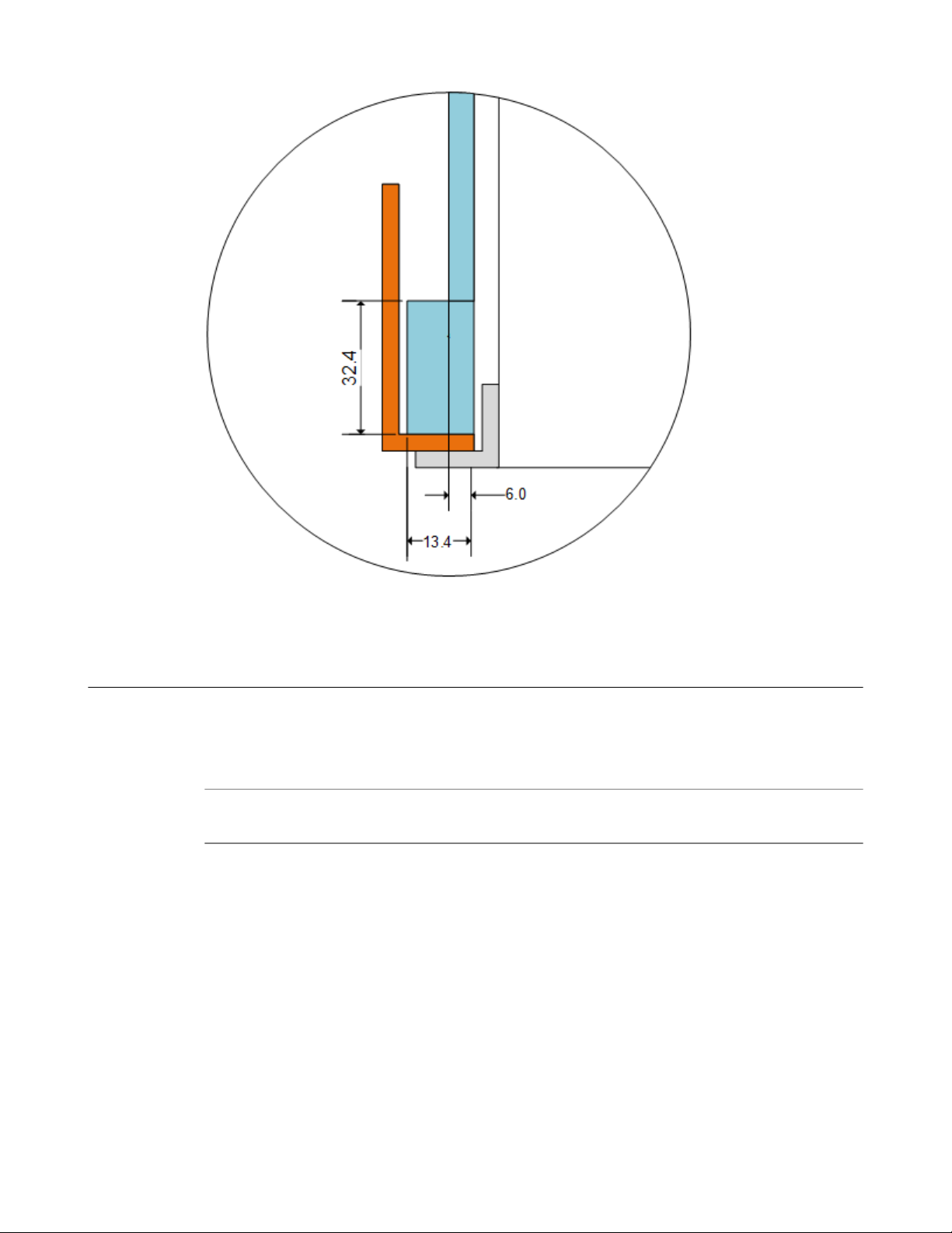
Chassis rack-mount spatial requirements
The i2000/i4000 Series platforms ship with a rack mount kit to help install the system more easily. This
kit requires that the rack or cabinet has certain clearances and spacing, as shown here.
emplacée par une batterie de type incorrect. Mettre
Page 42

Environmental Guidelines
42
Figure 11: Rack mounting spatial requirements for the i2000/i4000 Series platform
Page 43
Platform Guide: i2000/i4000 Series
Guidelines f
Figure 12: Detailed view of rack mounting spatial requirements
or power supplies
All iSeries platforms support either single or dual power supplies. When your system includes dual
power supplies, both supplies must be of the same type. To verify this, make sure that the supplies have
matching base part numbers (PWR-XXXX). You can find the base part number printed on the label on
top of the individual power supply.
Note: The full part number is a nine digit number (PWR-XXXX-YY). The base part number is seven digits
and must match, but the suffix (-YY) does not need to match.
43
Page 44

Environmental Guidelines
Figure 13: Example of label to check PWR-XXXX part number
If you cannot read the base part number, ensure that the pull handles are both in a horizontal orientation
and that the sheet metal on the power cord face for each supply has the same perforation shapes.
When you add or replace a power supply unit in your system, be sure to verify the supply's features and
that the PWR-XXXX part numbers match to ensure that you have the correct supply.
Guidelines for AC-powered equipment
An AC-powered installation must meet these requirements:
•
Use a 15 amp external branch circuit protection device to install the unit.
• Use one power feed for each individual power supply.
Important: The platform must be installed in a RESTRICTED ACCESS LOCATION, such as a central
office or customer premises environment.
Note: The power cables included with this unit ar
with other electrical appliances.
Note: These guidelines apply to ST
multiple connections to the AC MAINS SUPPLY:
• The building installation shall provide a means for connection to protective earth; and
• The equipment is to be connected to that means; and
• A SERVICE PERSON shall check whether or not the socket-outlet from which the equipment is to be
powered provides a connection to the building protective earth. If not, the SERVICE PERSON shall
arrange for the installation of a PROTECTIVE EARTHING CONDUCTOR from the separate
protective earthing terminal to the protective earth wire in the building.
ATIONARY PLUGGABLE EQUIPMENT TYPE A with simultaneous
e for exclusive use with this unit and should not be used
44
Caution: High leakage curr
ent. Earth connection essential before connecting supply.
Page 45

Guidelines for DC-powered equipment
A DC-powered installation must meet these requirements:
Use a 15 amp external branch circuit protection device to install the unit.
•
• For permanently connected equipment, incorporate a readily accessible disconnect in the fixed wiring.
• Use only copper conductors.
• Cabling for the system must be grounded on both sides.
• Use one power feed for each individual power supply.
Caution: Install DC-powered equipment only in restricted access areas, such as dedicated equipment
rooms, equipment closets, or similar locations.
Avertissement : Installer le matérial alimenté par courant continu uniquement dans des zones à accès
r
eglementé, telles que des salles de matériel, des armoires de materiel ou tout emplacement similaire.
Platform Guide: i2000/i4000 Series
Platform airflow diagram
When you install the platform into a rack, it is important to understand the unit's airflow direction so that
you can ensure proper cooling.
The platform employs a negative pressure fan system, which draws cold air in from the front of the
chassis.
45
Page 46

Environmental Guidelines
46
Figure 14: Airflow in iSeries platforms
Page 47

Platform Specifications
General specifications for system features
This table lists general specifications for system features for BIG-IP® iSeries platforms.
Item Specification
Transceiver modules hot
swap
Power supply hot swap Support for hot swap of the power supplies in dual supply systems
Jumbo frames Support for maximum Ethernet frame size of 9216 bytes and MTU of 9128
urboFlex™ Profiles TurboFlex Profiles are groupings of hardware-accelerated (FPGA) features
F5® T
Support for hot swap of optical transceiver modules
bytes
that are associated with a specific use case. TurboFlex Profiles are groupings
of hardware-accelerated features that are dependent on module licensing. If
BIG-IP® LTM® is licensed and provisioned, then the ADC profile is
available. If BIG-IP AFM™ is licensed and provisioned, then the Security
profile is available. TurboFlex Profiles are supported only in platforms
running a high performance license (x800). Also, TurboFlex Profile
availability varies depending on the platform series tier. For more
information, see F5 Platforms: TurboFlex Profiles at
support.f5.com/kb/en-us/products/big-ip_ltm/manuals/
product/f5-platform-turboflex-profiles.
Hardware specifications - i2000 (i2600/i2800) Series
This table lists hardware specifications for i2000 (i2600/i2800 Series platforms.
Item Specification
Dimensions H: 1.72 inches (4.37 cm) x W: 17.4 inches (44.20 cm) x D: 22.5 inches (57.15
cm) (per unit) 1U industry standard rack-mount chassis
Weight 20.0 pounds (9.07 kg) with one power supply (per unit)
Quick install rail kit adds 4.5 pounds (2.04 kg).
•
• Optional front-mount rack brackets add 2.5 pounds (1.13 kg).
• Additional power supply adds 2.0 pounds (0.91 kg).
Processor 1 x Dual-Core Intel® Xeon® processor (total 4 hyperthreaded logical processing
cores)
Communication
interfaces
Storage drive
capacity
2 x 10GbE SFP+
4 x 1GbE SFP ports
1 x 10/100/1000Base-T management port
1 x RJ45 console port
1 x RJ45 failover port
1 x USB 2.0 interface
1 x 500 GB Enterprise Class hard disk drive (HDD)
Page 48

Platform Specifications
Item Specification
RAM 16 GB
AC power supply 1 x 250 W 100-240 VAC(+/- 10%) AUTO Switching Platinum
DC power supply 1 x 650W DC
1 x NEMA 5-15P power cords
Operating range: 44-72 VDC
Minimum start up voltage: 44 VDC
Note: Power supply will not start below 44 VDC.
Important: Specifications ar
e subject to change without notification.
Hardware specifications - i4000 (i4600/i4800) Series
This table lists hardware specifications for i4000 (i4600/i4800) Series platforms.
Item Specification
Dimensions H: 1.72 inches (4.37 cm) x W: 17.4 inches (44.20 cm) x D: 22.5 inches (57.15
cm) (per unit) 1U industry standard rack-mount chassis
Weight 20.0 pounds (9.07 kg) with one power supply (per unit)
Quick install rail kit adds 4.5 pounds (2.04 kg).
•
• Optional front-mount rack brackets add 2.5 pounds (1.13 kg).
• Additional power supply adds 2.0 pounds (0.91 kg).
Processor 1 x Quad-Core Intel® Xeon® processor (total 8 hyperthreaded logical processing
cores)
Communication
interfaces
4 x 10GbE SFP+
8 x 1GbE SFP ports
1 x 10/100/1000Base-T management port
1 x RJ45 console port
1 x RJ45 failover port
1 x USB 2.0 interface
48
Storage drive
capacity
RAM 32 GB
AC power supply 1 x 250 W 100-240 VAC(+/- 10%) AUTO Switching Platinum
DC power supply 1 x 650W DC
Important: Specifications ar
1 x 500 GB Enterprise Class hard disk drive (HDD)
1 x NEMA 5-15P power cords
Operating range: 44-72 VDC
Minimum start up voltage: 44 VDC
Note
: Power supply will not start below 44 VDC.
e subject to change without notification.
Page 49

Environmental operating specifications
This table lists platform environmental operating specifications.
Item Specification
Operational temperature 32 to 104°F (0 to 40°C)
Operational relative humidity 5% to 85% (40°C) non-condensing
Up to 93% (40°C) non-condensing for a maximum of 96 hours
Non-operational temperature -40 to 158°F (-40 to 70°C)
Platform Guide: i2000/i4000 Series
Non-operational relative
humidity
5% to 93% (40°C) non-condensing
Power specifications - i2000 (i2600/i2800) Series
This table lists power specifications for i2000 (i2600/i2800) Series platforms.
Item Single power supply Dual power supply
Idle power draw (AC power) 110VAC input: 70W
AC input: 70W
220V
Typical power draw (AC
power; 50% load; temp 25°C)
Typical power draw (DC
power; 50% load; temp 25°C)
Maximum power draw (AC
power)
Maximum power draw (DC
power)
Typical heat generated (AC
power)
110VAC input: 95W
220VAC input: 95W
48VDC input: 105W 48VDC input: 115W
110VAC input: 120W
220VAC input: 120W
48VDC input: 125W 48VDC input: 140W
110VAC input: 325 BTU/hour
220VAC input: 345 BTU/hour
110VAC input: 80W
220VAC input: 75W
110VAC input: 100W
220VAC input: 100W
110VAC input: 120W
220VAC input: 120W
110VAC input: 325 BTU/hour
220VAC input: 345 BTU/hour
Typical heat generated (DC
power)
Maximum heat generated (AC
power)
Maximum heat generated (DC
power)
Important: Specifications ar
48VDC input: 360 BTU/hour 48VDC input: 395W
410 BTU/hour 410 BTU/hour
430 BTU/hour 480 BTU/hour
e subject to change without notification.
Power specifications - i4000 (i4600/i4800) Series
This table lists power specifications for i4000 (i4600/i4800) Series platforms.
49
Page 50

Platform Specifications
Item Single power supply Dual power supply
Idle power draw (AC power) 110VAC input: 95W
AC input: 90W
220V
Typical power draw (AC power; 50% load;
temp 25°C)
Typical power draw (DC power; 50% load;
temp 25°C)
Maximum power draw (AC power) 110VAC input: 165W
Maximum power draw (DC power) 48VDC input: 165W 48VDC input: 180W
Typical heat generated (AC power) 110VAC input: 445 BTU/
Typical heat generated (DC power) 48VDC input: 465 BTU/
Maximum heat generated (AC power) 565 BTU/hour 550 BTU/hour
Maximum heat generated (DC power) 565 BTU/hour 615 BTU/hour
Important: Specifications ar
e subject to change without notification.
110VAC input: 130W
220VAC input: 125W
48VDC input: 135W 48VDC input: 145W
220VAC input: 160W
hour
220VAC input: 430 BTU/
hour
hour
110VAC input: 95W
220VAC input: 95W
110VAC input: 130W
220VAC input: 130W
110VAC input: 160W
220VAC input: 160W
110VAC input: 445 BTU/
hour
220VAC input: 445 BTU/
hour
48VDC input: 495W
Safety requirements
This equipment complies with these requirements of the Low Voltage Directive 2014/35/EU:
EC Type Examination Certificates: Master Contract 252302
CB Scheme
EN 60950-1:2006+A11:2009+A1:2010+A12:2011+A2:2013
IEC 60950-1:2005, A1:2009+A2:2013
CSA 60950-1-07, Including A1:2011+A2:2014
ANSI/UL 60950-1-2014
EMC requirements
USA--FCC Class A, Canada--Industry Canada Class A
This equipment complies with Part 15 of FCC Rules. Operation is subject to these two conditions:
1. This equipment may not cause harmful interference.
2. This device must accept any interference received, including interference that may cause undesired
operation.
50
opean Union
Eur
This equipment complies with these requirements of the EMC Directive 2014/30/EU:
Page 51

As Telecommunication Network Equipment (TNE) in Both Telecom Centers and Other than Telecom
Centers per (as applicable):
ETSI EN 300 386 V1.6.1 (2012)
EN 55032:2012/AC:2013
EN 61000-3-2:2014
EN 61000-3-3:2013
As Information Technology Equipment (ITE) Class A per (as applicable):
EN 55024:2010
EN 55032:2012/AC:2013
EN 61000-3-2:2014
EN 61000-3-3:2013
Acoustic and altitude specifications
Platform Guide: i2000/i4000 Series
This table lists acoustic levels and operational altitude specifications for iSeries platforms.
Specification type Detail Value Notes
Acoustic Sound power 72.72 dBA A-weighted Sound Power at 27°C full
Altitude Operational 6,000 Feet Per Telcordia GR-63-CORE, section
Airflow specifications
This table lists airflow movement specifications for BIG-IP® iSeries platforms.
: Fan tray airflow measurements are taken at 100% duty cycle and in open air.
Note
Non-operational 40,000 Feet
system load.
4.1.3: This unit is functional when
installed at elevations between 60m (197
feet) below sea level and 1800m (6000
feet) above sea level at the aisle ambient
temperatures of 40°C.
Note: NEBS-certified platforms conform
to NEBS specifications above 6000 feet.
Platform Value (max)
i2000/i4000 92 CFM
Restriction of Hazardous Substances Directive (RoHS) for China
Products listed on this declaration comply with the Restriction of Hazardous Substances (RoHS) directive
1/65/EU, and produce required technical documentation in compliance with EN50581:2012.
201
51
Page 52

Platform Specifications
In accordance with China's Management Methods for the Restriction of the Use of Hazardous Substances
in Electrical and Electronic Products #32, the following information is provided regarding the names and
concentration levels of toxic substances or hazardous substances that may be contained in the following
product relative to the standards set by the Standardization Administration of the People's Republic of
China.
52
Page 53

Repackaging Guidelines
About repackaging the platform
If it becomes necessary to transport the platform to another location or return it to F5® Networks, these
guidelines will help ensure that you repackage the platform properly
You can perform a disk erase operation to erase all sensitive data from storage drives (for example, solidstate drives and hard disk drives) before you return a platform to F5. For more information, see F5
Platforms: Essentials at support.f5.com/kb/en-us/products/big-ip_ltm/manuals/
product/f5-plat-hw-essentials.html.
Important: Before returning any equipment, contact F5 to obtain a Service Order (SO) or Return
Material Authorization (RMA) case number.
.
Important: Y
platform.
Note: Be sur
shipments.
Note: Do not include any cables, r
are returning the platform to F5.
ou must use shipping materials and packaging provided by F5 when repackaging the
e to keep a record of the tracking number and ship date. These will be needed to track lost
Repackage the platform
The iSeries
1. Halt the platform using the LCD panel.
2. Disconnect the AC power cord or DC power supply terminal from the power supplies.
3. Disconnect the network cables and other cables from the chassis, and then remove any optical
modules.
4. Remove the chassis from the rack.
5. Remove all installation hardware from the chassis.
6. Place the chassis onto the bottom foam in the shipping box.
7. Place the top foam pieces into the slot on the bottom foam.
8. Close and seal the shipping box.
platforms must be shipped in F5®-provided packaging.
emovable transceiver modules, GBICs, or other peripheral items if you
Page 54

Repackaging Guidelines
54
Page 55

Returned Material Data Security Statement
About returned material data security
Follow these data security guidelines when returning equipment to F5®for reprocessing or repair
guidelines include reprocessing procedures and optional customer-end procedures.
About memory technologies used in F5 equipment
F5®equipment contains volatile, battery-backed volatile, and non-volatile memory
all traces of data on power down. Battery-backed volatile memory retains data as long as battery charge is
maintained. Non-volatile memory retains data indefinitely.
Volatile memory
Volatile memory loses all traces of data on power down; therefore, customer data that is stored in volatile
memory is secure when power is removed from the platform. No further action is required by customers
for equipment that includes volatile memory.
Battery-backed volatile memory
This F5® platform contains a coin battery for maintaining BIOS settings and the system clock. All data
maintained by the coin battery is used only for system specific tasks. No customer data is maintained by
the battery-backed volatile memory. No further action is required by customers for equipment that
includes volatile memory.
. The
. Volatile memory loses
Non-volatile memory
F5® platforms include various non-volatile memory components. These non-volatile memory
components can be categorized as either user inaccessible or user accessible.
Inaccessible non-volatile memory components are programmed during manufacture or software
installation. The data stored in user inaccessible non-volatile memory is used for setting voltage levels,
determining the sequence of operational events, and the managing appliance operational condition. Data
held within user inaccessible, non-volatile memory represents no data security risk to customers. User
inaccessible, non-volatile memory cannot be modified by appliance users, and therefore, contains no
customer data.
Inaccessible non-volatile memory
This table lists the inaccessible non-volatile memory in this system.
Description Data Customer
Programmable firmware stores Firmware No
Switch Card SEEPROM Platform ID, serial number, part number, and so on. No
PHY EEPROMs PHY MAC address No
data
Page 56
Returned Material Data Security Statement
Accessible non-volatile memory
This table lists the accessible non-volatile memory in this system. Not all platform variants include all of
these non-volatile memory items.
Description Data Customer
Hard disk drive (HDD) F5® product software,
customer configuration, and
log files
Always-On Management
(AOM) Flash chip (soldereddown flash chip)
AOM boot code and customer
custom configuration
About removing data from F5 components
For components that contain sensitive customer data and cannot be removed from your F5® system, you
can take optional steps to remove the data from these components before you return the system to F5 for
processing.
Remo
ve sensitive data from storage drives
The hard disk drive (HDD) and solid-state drive (SSD) components included in F5® platforms might
include sensitive customer data. If you purchase the HDD removal SKU, you can remove the HDD/SSD
and coin battery, and these components will be replaced during F5 reprocessing. Otherwise, HDD and
SSD components are processed by F5 through standard processing. You can perform a disk erase
operation on your system to remove sensitive customer data.
Data security
data
Yes Standard reprocessing
Yes Standard reprocessing
method
or customer removal
or customer action
Perform a disk erase operation using the F5 Disk Erase utility to remove all data on hard disk
drives (HDDs) or solid-state drives (SSDs) using a single-pass, zero write disk erase operation. For
more information about storage drive maintenance, see F5® Platforms: Essentials at
support.f5.com/kb/en-us/products/big-ip_ltm/manuals/product/f5-plat-hwessentials.html.
Remove IP address data from Always-On Management
If you have configured an IP address for the Always-On Management (AOM) subsystem, you can
remove the customized IP address from the system before returning it to F5® Networks.
1. Connect to the system using the serial console.
2. Open the AOM Command Menu.
Esc (
3. Manually assign a new management IP address, netmask, and gateway by typing n when prompted
about using DHCP. At the prompts, type 0.0.0.0 for IP address (required), and values for netmask
(required), and gateway (optional).
A confirmation message displays the configured management IP address, netmask, and gateway.
4. (Optional) Type i to verify the assigned addresses.
56
Page 57

Legal Notices
Legal Notices
Publication Date
This document was published on
Publication Number
MAN-0640-02
Copyright
Copyright © 2018, F5 Networks, Inc. All rights reserved.
F5 Networks, Inc. (F5) believes the information it furnishes to be accurate and reliable. However, F5
assumes no responsibility for the use of this information, nor any infringement of patents or other rights
of third parties which may result from its use. No license is granted by implication or otherwise under
any patent, copyright, or other intellectual property right of F5 except as specifically described by
applicable user licenses. F5 reserves the right to change specifications at any time without notice.
Trademarks
For a current list of F5 trademarks and service marks, see http://www.f5.com/about/guidelines-policies/
trademarks.
All other product and company names herein may be trademarks of their respective owners.
Patents
This product may be protected by one or more patents indicated at: https://f5.com/about-us/policies/
patents.
March 8, 2019.
Export Regulation Notice
This product may include cryptographic software. Under the Export Administration Act, the United
States government may consider it a criminal offense to export this product from the United States.
RF Interference Warning
This is a Class A product. In a domestic environment this product may cause radio interference, in which
case the user may be required to take adequate measures.
FCC Compliance
This equipment has been tested and found to comply with the limits for a Class A digital device pursuant
to Part 15 of FCC rules. These limits are designed to provide reasonable protection against harmful
interference when the equipment is operated in a commercial environment. This unit generates, uses, and
can radiate radio frequency energy and, if not installed and used in accordance with the instruction
manual, may cause harmful interference to radio communications. Operation of this equipment in a
residential area is likely to cause harmful interference, in which case the user, at his own expense, will be
required to take whatever measures may be required to correct the interference.
Page 58

Legal Notices
Any modifications to this device, unless expressly approved by the manufacturer, can void the user's
authority to operate this equipment under part 15 of the FCC rules.
Canadian Regulator
This Class A digital apparatus complies with Canadian ICES-003.
Standards Compliance
This product conforms to the IEC, European Union, ANSI/UL and Canadian CSA standards applicable to
Information Technology products at the time of manufacture.
Brazil Compliance
This product is homologated by ANATEL, in accordance with the procedures regulated by Resolution n.
242/2000 and meets the technical requirements applied.
This product is homologated by ANATEL, in accordance with the procedures regulated by Resolution n.
242/2000 and meets the technical requirements applied including the exposure limits of the Specific
Absorption Rate for electric, magnetic and electromagnetic fields of radio frequency in accordance with
Resolutions 303/2002 and 533/2009.
This equipment is not subject to the protection from harmful interference and may not cause interference
with duly authorized systems.
For more information, see the ANATEL website at www.anatel.gov.br.
VCCI Class A Compliance
This is a Class A product. In a domestic environment, this product may cause radio interference, in which
case the user may be required to take corrective actions. VCCI-A
y Compliance
この製置は、クラス A 情報技術製置です。この製置を家庭環境で使用す ると電波妨害を引き
起こすことがあります。 この場合には使用者が適切 な対策を講ずるよう要求されることがあ
ります。 VCCI-A
58
Page 59

Index
Index
10G interfaces, See SFP+ interf
10GbE interfaces, See SFP+ interfaces.
aces.
A
AC power supplies
and hot swapping 33
AC-powered equipment
guidelines 44
acoustic specifications 51
airflow specifications 51
alarm LED 14
alert conditions
defining custom alerts 16
alerts
clearing 11
clearing all from the LCD 7
viewing using the LCD 7
altitude operational specifications 51
Always-On Management (AOM)
about 20
configuring management network 22
creating an AOM admin user account 21
disabling network configuration 23
removing IP address data 56
setting SSH idle session timeout 22
AOM, See Always-On Management (AOM).
AOM Command Menu
about 20
accessing using serial console 20
accessing using SSH 22
options 20
AOM management interface
configuring using the LCD 8
enabling or disabling DHCP 8
setting the gateway 8
setting the IP address 8
setting the routing prefix 8
Auto-MDI/MDIX 18
China material content listing, See China RoHS Directive
standards.
China RoHS Directive standards 51
Configuration utility
about managing interfaces 17
licensing the platform 32
viewing status of all interfaces 18
cooling system
platform airflow diagram 45
D
data communications equipment (DCE) 18
data terminal equipment (DTE) 18
DC power supplies
and hot swapping 37
and safety requirements 37
DC-powered equipment
guidelines 45
device service clustering (DSC) 27
disk erase operation
about performing 53
DSC, See device service clustering (DSC).
dual stack management IP addresses 29
duplex mode 18
dynamic routing protocols 47
E
electromagnetic compatibility (EMC) certifications 50
electrostatic discharge (ESD) 41
EMC certifications 50
EMI compliance
when connecting cables 27
environmental guidelines 51
See also China RoHS Directiv
environmental operating specifications 49
ESD, See electrostatic discharge (ESD).
Ethernet hub requirements 6
e standards.
C
cables
connecting 27
for failover 27
for power 27
CD/DVD-ROM drives
support for 6
chassis
ventilation 41
chassis ground lug
locating 26
chassis locator LED
enabling/disabling 13
chassis power LEDs 15
chassis ventilation
diagram 45
F
faceplate
removing the protective films 27
failover cables
connecting 27
FPGA features, See T
urboFlex Profiles.
G
Gigabit Ethernet 6
ground lugs
connecting to ground terminal 27
locating 26
location 5
guidelines
battery replacement 41
59
Page 60

Index
H
halt oper
halting the unit
hard disk drives (HDDs) specifications 47, 48
hard-wired failover 27
hardware
hardware requirements
hardware specifications
hazardous substance restrictions, See China RoHS Directive
standards.
hot swap
hubs 6
ation 10
using the LCD 7
AC-powered equipment 44
DC-powered equipment 45
for peripherals 6
for i4000 (i4600/i4800) Series platforms 48
i2000 (i2600/i2800 Series platforms 47
i2000 (i2600/i2800) Series platforms 49
and AC power supplies 33
and DC power supplies 37
and transceiver modules 47
I
indicator LEDs
location 5
installation
guidelines 41
performing using serial console 6
recommendations for 41
spacing between units 41
interfaces
about 17
about configuring 17
about managing 17
duplex mode 18
for SFP+ 17
media type 18
viewing status of a specific interface using tmsh 17
viewing status of all interfaces using Configuration utility
18
viewing status of all interfaces using tmsh 17
viewing valid media types 19
viewing valid media types using tmsh 19
J
jumbo frames 47
L
LCD
about using 9
putting into men
removing the protective film 29
using to configure the management IP address 29
LCD brightness
configuring 12
configuring using the LCD 8
LCD menu options 7
u mode 9
LCD menus
about 7
ts menu options 7
Aler
and Options menu options 8
Setup menu options 8
System menu options 7
LED
network interface 20
LEDs
about 14
alarm 14
chassis power 15
defining custom alerts 16
for power supply, AC 15
power supply, DC 15
status 14
license
configuring 32
Locator LED
configuring using the LCD 8
low voltage directive 50
M
maintenance
and replaceable components 33
replacing an AC power supply unit 35
replacing DC power supply units 38
management interface
configuring using the LCD 8
connecting Ethernet cable 27
enabling or disabling DHCP 8
setting the gateway 8
setting the IP address 8
setting the routing prefix 8
management IP addresses
configuring dual stack 29
configuring using LCD 29
memory technologies
about 55
battery-backed volatile memory 55
defined 55
volatile memory 55
N
negative pressure fan system 45
network interface LEDs
appearance of 20
f
or SFP 20
for SFP+ 20
O
optical interfaces, See interfaces.
optical transceiver modules
specifications 17
60
Page 61

Index
P
pass-through adapter, See RJ45F to RJ45M rolled ser
adapter.
pinouts for cables
specifications 17
platform
about 5
about grounding 26
about installing 25
about managing interfaces 17
about returning for RMA 53
and hardware provided with 6
and replaceable components 33
clearing alerts 11
configuring LCD brightness 12
configuring the management IP address 29
halting 10
powering off/on 11
rebooting 9
repackaging 53
resetting 9
transporting 53
ventilation 41
platform airflow
diagram 45
platform cooling
diagram 45
platform photos 5
platform specifications
for disk drive 47, 48
for environmental 49
for hardware 47, 48
for memory 47, 48
for operating 49
for power for i4000 (i4600/i4800) Series platforms 49
for power supply 47, 48
for processor 47, 48
for solid-state drive 48
power for i2000 (i2600/i2800) Series platforms 49
platform ventilation
diagram 45
ports
location 5
power cables
and locking feature 27
connecting 27
power LEDs 15
power off/on operation 11
power specifications
for i4000 (i4600/i4800) Series platforms 49
po
wer for i2000 (i2600/i2800) Series platforms 49
power supplies
about 33
guidelines 43
power supplies, AC
and LEDs 15
power supplies, DC
LEDs 15
power supply specifications 47, 48
power supply units (PSUs)
connecting DC power 38
ial
power supply units (PSUs) (contin
replacing a DC power supply unit 38
replacing an AC power supply unit 35
powering off/on the unit
using the LCD 7
ued)
Q
qkview utility 27
quick-install rail kit mount
and hardware for 25
quick-install rail kits 25
R
rack mount
and quick-install rail kits 25
general environmental guidelines 41
rack-mount
spatial requirements for 41
rail lock brackets
installing 26
rail mount
installing rail lock brackets 26
reboot operation
using the LCD 9
rebooting the unit
using the LCD 7
redundancy
for system 27
redundant system configuration 27
remote administr
repackaging
about 53
repackaging process
for platform 53
replaceable components
about 33
and AC power supplies 33
and DC power supplies 37
reset operation
using the LCD 9
resetting the unit
using the LCD 7
Return Material Authorization (RMA) 53
returned material data security
about 55
accessible non-volatile memory 56
and memory technologies 55
battery-backed volatile memory 55
inaccessible non-volatile memory 55
removing data from components 56
volatile memory 55
RJ45F to RJ45M rolled serial adapter 27
RMA, See Return Material Authorization (RMA).
ation 6
S
safety agency approvals 50
serial console
and hardware installation 27
f
or hardware installation 6
61
Page 62

Index
serial failover 27
serial port
setting baud rate 8
serial port baud rate
configuring using the LCD 8
SFP ports
and LEDs 20
SFP+ interfaces
about 17
SFP+ ports
and LEDs 20
specifications
China RoHS 51
or acoustic levels 51
f
for airflow 51
for altitude operational 51
for disk drive 47, 48
for hard disk drive (HDD) 47
for hardware 47, 48
for hardware operation 49
for memory 47, 48
for power for i4000 (i4600/i4800) Series platforms 49
for power supply 47, 48
for processor 47, 48
for system features 47
hard disk drive (HDD) 48
power for i2000 (i2600/i2800) Series platforms 49
status LED 14
storage drives
and disk erase operation 53
removing sensitive data 56
switches 6
system
resetting 20
resolving when locked up 20
system redundancy 27
V
ventilation
diagram 45
W
warnings
environmental 41
warnings, environmental 51
See also China RoHS Directive standards.
T
TMOS, See Traffic Management Operating System.
TMOS Shell (tmsh)
about managing interfaces 17
and interface command 19
viewing status of all interfaces 17
viewing the status of a specific interface 17
viewing valid media types 19
TMOS Shell (tmsh) interface command 19
tmsh, See TMOS Shell (tmsh).
Traffic Management Operating System
relation to AOM 20
transceiver modules
and hot swap support 47
transporting the platform 53
TurboFlex Profiles
about 47
U
USB flash drives
support for 6
USB ports
supported CD/DVD-ROM drives 6
62
 Loading...