

Ezgo RXV golf car 2008, rxv freedom 2008, rxv shuttle 2+2 2008 Owner's Manual

OWNER’S MANUAL ELECTRIC
607747-FR
RXV FLEET
FREEDOM
®
SHUTTLE
™
2+2
ISSUED FEBRUARY 2008
MANUEL D’UTILISATION VOITURE ÉLECTRIQUE
publié en février 2008

WASH HANDS
AFTER HANDLING!
Battery posts,
terminals and related
accessories contain
lead and lead compounds,
chemicals known
to cause cancer and
reproductive harm.
BATTERY WARNING
WASH HANDS
AFTER HANDLING!
WARNING: Battery posts, terminals and related
accessories contain lead and lead compounds,
chemicals known to cause cancer and reproductive harm.
BATTERIES
CONTAIN LEAD
AND RELATED PARTS
!
<
14
˚
25
%
DO NOT
DRIVE ACROSS
SLOPES IN
EXCESS OF 14˚
DANGER
SAFETY
1For any questions on material contained in this manual, contact an authorized representative for clarification.
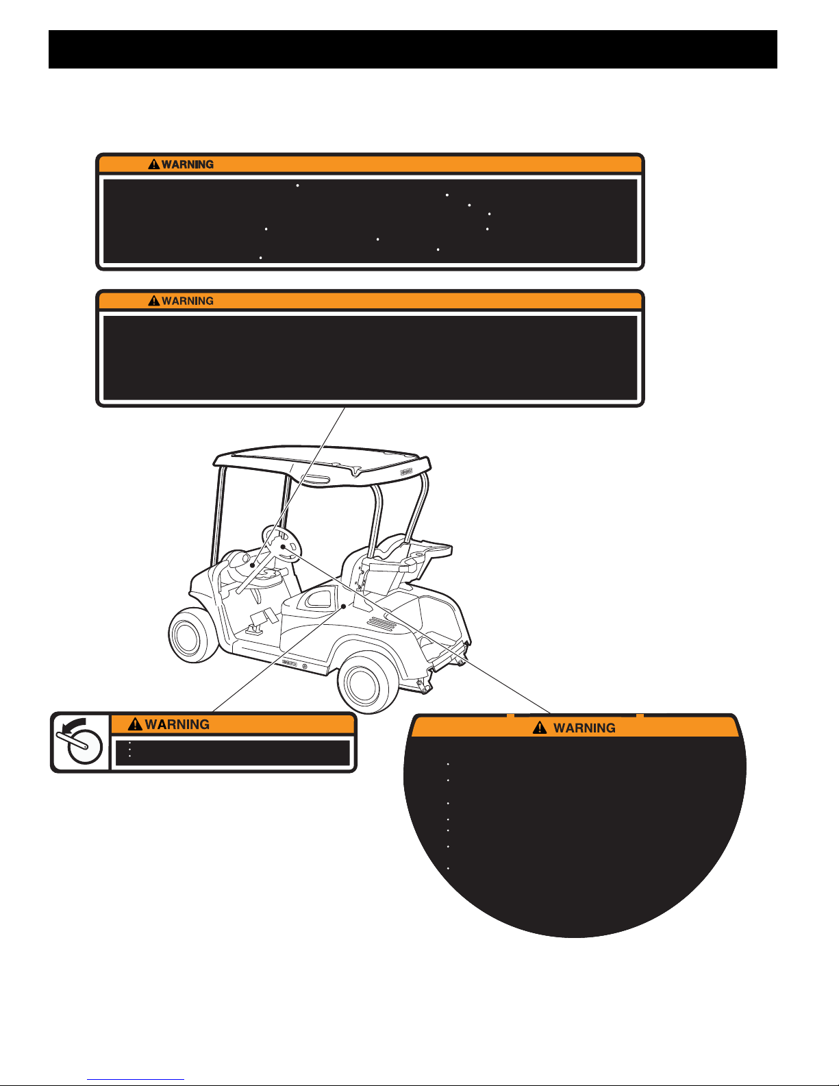
Read and understand all labels located on the vehicle. Always replace any damaged or missing labels.
On steep hills it is possible for vehicles to coast at greater than normal speeds encountered on a flat surface. To pre-
vent loss of vehicle control and possible serious injury, speeds should be limited to no more than the maximum speed
on level ground. See GENERAL SPECIFICATIONS. Limit speed by applying the service brake.
Catastrophic damage to the drivetrain components due to excessive speed may result from driving the vehicle above
specified speed. Damage caused by excessive speed may cause a loss of vehicle control, is costly, is considered
abuse and will not be covered under warranty.
Use extra caution when towing the vehicle(s). Do not tow a single vehicle at speeds in excess of 12 mph (19 kph). Do
not tow more than three vehicles at a time. Do not exceed 5 mph (8 kph) while towing multiple vehicles. Towing the
vehicle at above the recommended speed may result in personal injury and /or damage to the ve hicle and other pr operty. Vehicles equipped with the AC Drive motor must be towed with the Run-Tow switch, located under the passenger
seat, in the ‘Tow’ position.
If the vehicle is to be used in a commercial environment, signs similar to the ones illustrated should be used to warn of
situations that could result in an unsafe condition
Be sure that this manual remains as part of the permanent service record should the vehicle be resold.
NOTES, CAUTIONS AND WARNINGS
Throughout this guide NOTE, CAUTION and WARNING
will be used.
A NOTE indicates a condition that should be observed.
A CAUTION indicates a condition that may result in
damage to the vehicle.
A WARNING indicates a hazardous condition
that could result in severe injury or death.
(NOTES, CAUTIONS AND WARNINGS CONTINUED ON INSIDE OF BACK COVER)
A DANGER indicates a hazardous situation
that could result in death or serious injury.
Please observe these NOTES, CAUTIONS and WARNINGS; be aware that servicing a vehicle requires
mechanical skill and a regard for conditions that could be
hazardous. Improper service or repair may damage the
vehicle or render it unsafe.
Battery posts, terminals and related accessories contain lead and lead compounds. Wash
hands after handling.

OWNER’S GUIDE
ELECTRIC POWERED
FLEET & PERSONAL GOLF CARS
RXV GOLF CAR
RXV FREEDOM™
RXV SHUTTLE 2 + 2
STARTING MODEL YEAR 2008
ISSUED OCTOBER 2007
E-Z-GO Division of TEXTRON, In c. reserves t he right to inc orporate engi neering and d esign chang es to products in this Manual, without obligation to include
these changes on units leased/sold previously.
The information contained in this Manual may be revised periodically by the E-Z- GO Division, and therefore is subject to change without notice.
The E-Z-GO Division DISCLAIMS LIABILITY FOR ERRO RS IN THIS MANUAL, and the E-Z-GO Division SPECIFICALLY DISCLAIMS LIABILITY FOR INCI-
DENTAL AND CONSEQUENTIAL DAMAGES resulting from the use of the information and materials in this Manual.
TO CONTACT US
NORTH AMERICA:
TECHNICAL ASSISTANCE & WARRANTY PHONE: 1-800-774-3946, FAX: 1-800-448-8124
SERVICE PARTS PHONE: 1-888-GET-EZGO (1-888-438-3946), FAX: 1-800-752-6175
INTERNATIONAL:
SALES PHONE: 001-706-798-4311, FAX: 001-706-771-4609
E-Z-GO DIVISION OF TEXTRON, INC., 1451 MARVIN GRIFFIN ROAD, AUGUSTA, GEORGIA USA 30906-3852
Owner’s Guide
Page i

GENERAL INFORMATION
This vehicle has been designed and manufactured in the United States of America (USA) as
a ‘World Vehicle’. The Standards and Specifications listed in the following text originate in
the USA unless otherwise indicated.
The use of non Original Equipment Manufacturer (OEM) approved parts may void the
warranty.
Overfilling batteries may void the warranty.
BATTERY PROLONGED STORAGE
All batteries will self discharge over time. The rate of self discharge varies depending on the
ambient temperature and the age and condition of the batteries.
A fully charged battery will not freeze in winter temperatures unless the temperature falls
below -75° F (-60° C).
For winter storage, the batteries must be clean, fully charged and disconnected from any
source of electrical drain.
On all electric vehicles, set the key switch to ‘N’ and the ‘RUN/TOW’ switch, located under
the passenger seat, to the ‘TOW’ position before towing the vehicle.
As with all electric vehicles, the batteries must be checked and recharged as required or at a
minimum of 30 day intervals.
Page ii
Owner’s Guide

TABLE OF CONTENTS
SECTION TITLE PAGE NO.
SAFETY .................................................................................................... Inside Covers
GENERAL INFORMATION............................................................................................ ii
SAFETY INFORMATION ................................................................................................v
LABELS AND PICTOGRAMS ...................................................................................... ix
SERIAL NUMBER LOCATION ...................................................................................... 1
BEFORE INITIAL USE....................................................................................................1
PORTABLE CHARGER..................................................................................................2
PORTABLE CHARGER INSTALLATION............................................. ....... ...........2
USING THE CHARGER........................................... .............. ....... ....... .............. ....3
UNDERSTANDING THE CHARGER ......... ....... .............. ....... ....... ....... .............. ....3
LED OPERATION CODES.............................................. ....... .............. ....... ....... ....4
LED FAULT CODES.............................................................. ....... ....... .............. ....4
MAINTENANCE INSTRUCTIONS.......................................... ....... .............. ....... ....4
CONTROLS AND INDICATORS.................................................................................... 5
KEY SWITCH/DIRECTION SELECTOR ................................................................5
STATE OF CHARGE METER................................................................................5
HEADLIGHT SWITCH................................ .............. ....... ....... .............. ....... ....... ....6
TURN SIGNAL SWITCH...................................................................... ....... ....... ....6
HORN .................................................................................... ....... ....... .............. ....6
ACCELERATOR & BRAKE PEDALS.....................................................................6
PARKING BRAKE............................................. .............. ....... ....... .............. ....... ....6
RUN/TOW SWITCH.............. .............. ....... ....... .............. ....... ....... ....... .............. ....6
OPERATING THE VEHICLE.......................................................................................... 6
REGENERATIVE BRAKING .................................... ....... .............. ....... ....... ...........7
PEDAL-UP BRAKING.............................................. .............. ....... ....... .............. ....7
HIGH PEDAL DISABLE FEATURE............ .............. ....... ....... ....... .............. ....... ....7
STARTING AND DRIVING .... ....... .............. ....... ....... .............. ....... ....... ....... ...........7
STARTING VEHICLE ON A HILL........ .............. ....... ....... .............. ....... ....... ...........8
COASTING ............. ....... ....... .............. ....... ....... .............. ....... ....... .............. ....... ....8
LABELS AND PICTOGRAMS .................................. ....... ....... .............. ....... ....... ....8
SUN TOP AND WINDSHIELD ...................................................... ....... .............. ....8
VEHICLE CLEANING & CARE.......................................................................................8
VEHICLE CLEANING.......................... .............. ..................... .............. .............. ....8
REPAIR...........................................................................................................................9
LIFTING THE VEHICLE........ ....... .............. ....... ....... .............. ....... ....... .............. ....9
WHEELS AND TIRES...................................................................................................10
TIRE REPAIR........................................................... .............. ....... ....... ....... .........10
WHEEL INSTALLATION.................................................................................... ..11
LIGHT BULB REPLACEMENT.....................................................................................11
HEAD LIGHT BULB REPLACEMENT........................................... ....... ....... .........11
TURN SIGNAL BULB REPLACEMENT ............................................................. ..12
TAILLIGHT/BRAKE LIGHT BULB REPLACEMENT.............................................12
Owner’s Guide
Page iii

TABLE OF CONTENTS
SECTION TITLE PAGE NO.
TRANSPORTING THE VEHICLE ................................................................................. 12
TOWING......................................................................... ....... .............. ....... ....... .. 12
HAULING..................................... ....... ....... .............. ....... ....... ....... .............. ....... .. 13
SERVICE AND MAINTENANCE .................................................................................. 13
ROUTINE MAINTENANCE ... ..................... .............. .............. ..................... ......... 14
TIRE INSPECTION............... .............. ....... ....... ....... .............. ....... ....... .............. .. 14
REAR AXLE .............................................. ....... ....... .............. ....... ....... .............. .. 14
HARDWARE................................................................................. ....... .............. .. 14
CAPACITIES AND REPLACEMENT PARTS ........... ....... ....... .............. ....... ....... .. 15
PERIODIC SERVICE SCHEDULE....................................................... ....... ......... 16
BATTERIES AND CHARGING..................................................................................... 17
SAFETY.............................................. ....... .............. ....... ....... .............. ....... ....... .. 17
BATTERY. ....... .............. ....... ....... .............. ....... ....... .............. ....... ....... .............. .. 17
BATTERY MAINTENANCE.......................................................................................... 18
AT EACH CHARGING CYCLE ................................ ....... ....... .............. ....... ....... .. 18
MONTHLY.................................................................................... ....... ....... ....... .. 18
ELECTROLYTE LEVEL AND WATER....... .............. .............. .............. ................ 19
CLEANING BATTERIES
BATTERY REMOVAL & INSTALLATION.................................................................... 20
PROLONGED STORAGE ............................................................................................ 22
BATTERY CHARGING................................................................................................. 23
TROUBLESHOOTING.................................................................................................. 23
HYDROMETER ........................... ....... ....... .............. ....... ....... .............. ....... ....... .. 23
USING A HYDROMETER ..... ....... .............. ....... ....... ....... .............. ....... ....... ......... 24
GENERAL SPECIFICATIONS...................................................................................... 27
RXV ELECTRIC - FLEET VEHICLE SPECIFICATIONS............................. ......... 28
RXV ELECTRIC - FREEDOM VEHICLE SPECIFICATIONS ............... ....... ....... .. 29
RXV ELECTRIC - SHUTTLE 2 + 2 VEHICLE SPECIFICATIONS........................ 30
WARRANTY ................................................................................................................. 35
DECLARATION OF CONFORMITY (EUROPE ONLY) ................................................ 37
Page iv
Owner’s Guide

SAFETY INFORMATION
Read all of this manual to become thoroughly familiar with this vehicle. Pay particular attention to all Notes, Cautions and Warnings.
This manual has been designed to assist in maintaining the vehicle in acco rdance with proce dures developed b y the
manufacturer. Adherence to these procedures and troubleshooting tips will ensure the best possible service from the
product. To reduce the chance of personal injury or property damag e, the following m ust be carefully obser ved:
Certain replacement parts can be used independently and/or in combination with other accessories to modify an EZ-GO-manufactured vehicle to permit the vehicle to operate at or in excess of 20mph. When an E-Z-GO-manufactured vehicle is modified an any way by the Distributor, Dealer or customer to operate at or in excess of 20mph,
UNDER FEDERAL LAW the modified product will be a Low Speed Vehicle (LSV) subject to the strictures and
requirements of Federal Motor Vehicle Safety Standard 571.500. In these instances, pursuant to Federal law the
Distributor or Dealer MUST equip the product with headlights, rear lights, turn signals, seat belts, top, horn and all
other modifications for LSV’s mandated in FMVSS 571.500, and affix a Vehicle Identification Number to the product
in accordance with the requirements of FMVSS 571.565. Pursuant to FMVSS 571.500, and in accordance with the
State laws applicable in the places of sale and use of the product, the Distributor, Dealer or customer modifying the
vehicle also will be the Final Vehicle Manufacturer for the LSV, and required to title or register the vehicle as mandated by State law.
E-Z-GO will NOT approve Distributor, Dealer or customer modifications converting E-Z-GO products into LSV’s.
The Company, in addition, recomm ends that all E-Z -GO produ cts sold as personal transportation vehicles BE OPER-
ATED ONLY BY PERSONS WITH VALID DRIVERS LICENSES, AND IN ACCORDANCE WITH APPLICABLE STATE
REQUIREMENTS. This restriction is important to the SAFE USE AND OPERATION of the product. On behalf o f E- ZGO, I am directing that E-Z-GO Branch personnel, Distributors and Dealers advise all customers to adhere to this
SAFETY RESTRICTION, in connection with the use of all products, new and used, the Distributor or Dealer has reason to believe may be operated in personal transportation applications.
Information on FMVSS 571.500 can be obtained at Title 49 of the Code of Federal Regulations, section 571.500, or
through the Internet at the website for the U.S. Department of Transportation - at Dockets and Regulation, then to Title
49 of the Code of Federal Regulations (Transportation)
B
B
GENERAL
Many vehicles are used for a variety of tasks beyond the original intended use of the vehicle; therefore, it is impossible
to anticipate and warn against every possible combination of circumstances that may occur. No warnings can take the
place of good common sense and prudent driving practices.
Good common sense and prudent driving practices do more to pr event accid ents and injury than all of the wa rnings
and instructions combined. The manufacturer strongly suggests that all users a nd maintenance p ersonnel read this
entire manual paying particular attention to the CAUTIONS and WARNINGS contained therein.
If you have any questions regarding this vehicle, contact your closest representative or write to the address on the
back cover of this publication, Attention: Custome Care Department.
The manufacturer reserves the right to make design changes without obligation to make these changes on units previously sold and the information contained in this manual is subject to change without notice.
The manufacturer is not liable for errors in this ma nual or for incidental or consequential damages that resu lt fro m th e
use of the material in this manual.
This vehicle conforms to the current applicable standard(s) for safety and performance requirements.
These vehicles are designed and manufactured for off-road use. They do not conform to Federal Motor Vehicle Safety
Standards of the United States of America (USA) and are not equipped for o peration on public stre ets. Some communities may permit these vehicles to be operated on their streets on a limited basis and in accor dance with loca l ordinances.
With electric powered vehicles, be sure that all electrical accessories are grounded directly to th e battery (-) p ost.
Never use the chassis or body as a ground connection.
Owner’s Guide
Page v

SAFETY INFORMATION
Read all of this manual to become thoroughly familiar with this vehicle. Pay particular attention to all Notes, Cautions and Warnings.
Refer to GENERAL SPECIFICATIONS for vehicle seating capacity.
B
Never modify the vehicle in any way that will alter the weight distribution of the vehicle, decrease its stability
or increase the speed beyond the factory specification. Such modifications can cause serious personal injury
or death. Modifications that increase the speed and/or weight of the vehicle will extend the stopping distance and may
reduce the stability of the vehicle. Do not make any such modifications or changes. The manufa cturer proh ibits and
disclaims responsibility for any such modifications or any other alteration which would adversely affect the safety of the
vehicle.
Vehicles that are capable of higher speeds must limit their speed to no more than the speed of other vehicles when
used in a golf course environment. Additionally, speed should be further moderated by the environmental conditions,
terrain and common sense.
GENERAL OPERATION
Always use the vehicle in a responsible manner and maintain the vehicle in safe operatin g condition .
Always read and observe all warnings and operation instruction labels affixed to the vehicle.
Always follow all safety rules established in the area where the vehicle is being operated.
Always reduce speed to compensate for poor terrain or conditions.
Always apply service brake to control speed on steep grades.
Always maintain adequate distance between vehicles.
Always reduce speed in wet areas.
Always use extreme caution when approaching sharp or blind turns.
Always use extreme caution when driving over loose terrain.
Always use extreme caution in areas where pedestrians are present.
MAINTENANCE
Always maintain the vehicle in accordance with the manufacturer ’s periodic service schedule.
Always ensure that repairs are performed by those that are trained and qualified to do so.
Always follow the manufacturer’s maintenance procedures fo r the vehicle. Be su re to disable the vehicle before per-
forming any maintenance. Disabling includes removing the key from the key switch and remo val of a battery wire.
Always insulate any tools used within the battery area in order to prevent sparks or battery explosion caused by short-
ing the battery terminals or associated wiring. Remove the batteries or cover exposed terminals with an insulating
material.
Always check the polarity of each battery terminal and be sure to rewire the batteries correctly.
Always use specified replacement parts. Never use replacement parts of lesser quality.
Always use recommended tools.
Always determine that tools and procedures not specifically recommended by the manufactur er will not compro mise
the safety of personnel nor jeopardize the safe operation of the vehicle.
Always support the vehicle using wheel chocks and jack stands. Never get under a vehicle that is supported by a jack.
Lift the vehicle in accordance with the manufacturer’s instructions.
Always maintain the vehicle in an area away from exposed flame or persons who are smoking.
Always be aware that a vehicle that is not performing as designed is a potential hazard and mu st not be oper ated.
Always test drive the vehicle after any repairs or maintenance. All tests must be conducted in a safe area that is free of
both vehicular and pedestrian traffic.
Always replace damaged or missing warning, caution or information labels.
Always keep complete records of the maintenance history of the vehicle.
Page vi
Owner’s Guide

SAFETY INFORMATION
Read all of this manual to become thoroughly familiar with this vehicle. Pay particular attention to all Notes, Cautions and Warnings.
The manufacturer cannot anticipate all situations, therefore people attempting to maintain or repair the vehicle must
have the skill and experience to recognize and protect themselves from potential situations that could result in severe
personal injury or death and damage to the vehicle. Use extreme caution and, if unsure as to the potentia l for injur y,
refer the repair or maintenance to a qualified mechanic.
VENTILATION
Hydrogen gas is generated in the charging cycle of batteries and is explosive in concentr ations as low as 4 %.
Because hydrogen gas is lighter than air, it will collect in the ceiling of buildings necessitating proper ventilation. Five
air exchanges per hour is considered the minimum requirement.
Never charge a vehicle in an area that is subject to flame or spark. Pay particular attention to natural gas or propane
water heaters and furnaces.
Always use a dedicated circuit for each battery charger. Do not permit other appliances to be plugged into the receptacle when the charger is in operation.
Chargers must be installed and operated in accordance with charger manufacturers recommen dations or applicable
electrical code (whichever is higher).
B
B
Owner’s Guide
Page vii

SAFETY INFORMATION
Read all of this manual to become thoroughly familiar with this vehicle. Pay particular attention to all Notes, Cautions and Warnings.
Notes:
Page viii
Owner’s Guide

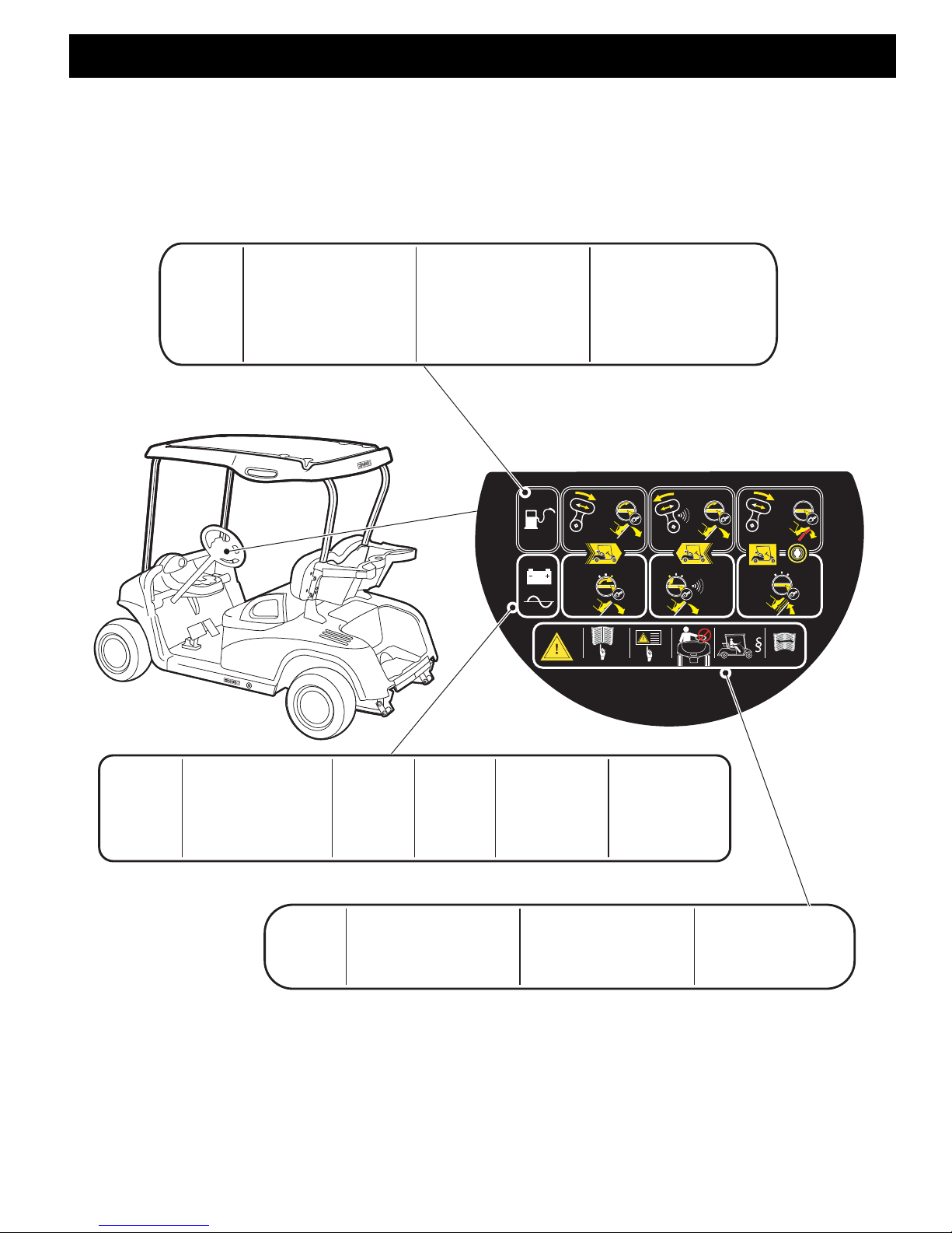
LABELS & PICTOGRAMS
Read all of this manual to become thoroughly familiar with this vehicle. Pay particular attention to all Notes, Cautions and Warnings.
LABELS & PICTOGRAMS
B
B
Owner’s Guide
Page ix
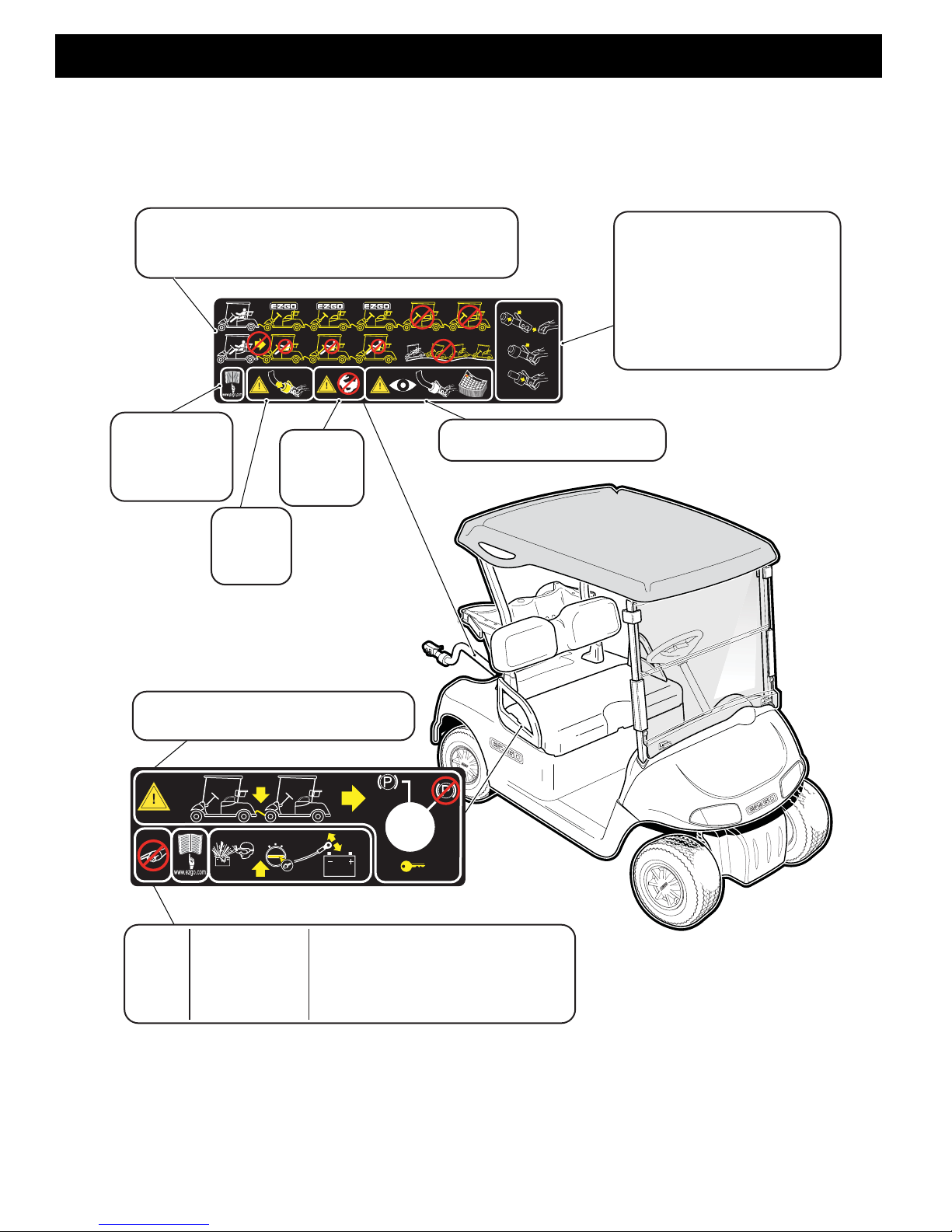
LABELS & PICTOGRAMS
Except where PERMITTED BY LAW:
To be operated by persons with valid drivers license, in accordance with state requirements. Operate from Driver’s side only.
Reduce the RISK OF ACCIDENTS:
For non-road use, and in designated areas only. Do not operate under the influence of drugs or alcohol.
AVOID FALLS from the vehicle:
All occupants must be fully seated, keep entire body inside vehicle and hold on while vehicle is in motion.
STARTING the vehicle:
Apply service brake , move direction selector to desired position and accelerate smoothly. On Gas Vehicle, direction selector is
the F-N-R. On Electric vehicle, direction selector is the key switch.
DO NOT OVERLOAD this vehicle:
Maximum vehicle payload is 800 lbs. (363 kg) including a maximum of 2 persons, options, and accessories.
Drive with CAUTION:
Drive slowly straight up and down slopes and in turns. Use care in reverse, congested areas, and wet or loose terrain.
STOPPING the vehicle:
To stop, release accelerator pedal and apply service brake.
PARKING the vehicle:
Before leaving vehicle , turn key ‘OFF’. On Gas vehicle, move the direction selector to “FORWARD” and engage park brake.
Failure to follow these instructions can result in SERIOUS INJURY or DEATH
Except where PERMITTED BY LAW:
NEVER drive on public roads. Drivers must possess a valid drivers license in accordance with local state law.
AVOID FALLS from the vehicle:
Do not start moving until all occupants are PROPERLY SEATED and HOLDING ON. KEEP entire body INSIDE VEHICLE while moving.
Reduce the RISK OF ACCIDENTS:
Always DRIVE SLOWLY in congested areas, on wet or loose terrain, and when backing up. DRIVE SLOWLY when turning and
AVOID sudden stops.
ALWAYS drive straight up and down slopes. Do not coast, use BRAKE when going down a slope. NEVER drive this vehicle under the influence
of drugs or alcohol.
This vehicle is NOT A TOY:
Drive responsibly. NEVER leave children unattended or allow children to play on the vehicle. NEVER leave the key in the vehicle when parked.
DO NOT OVERLOAD this vehicle:
NEVER carry more than 2 occupants on each bench seat. Do not exceed vehicle WEIGHT CAPACITY (see Owner’s Manual).
DO NOT MODIFY this vehicle:
NEVER alter this vehicle to increase travel speeds above factory specifications. ONLY authorized E-Z-GO dealers should alter the vehicle using
approved parts. Alterations not approved or tested by E-Z-GO can create unsafe conditions and increase your chance of having an accident.
Vehicle can roll, even on fairly level ground.
Turn key switch to ‘OFF’ before releasing brake.
Manual brake lever will release the park brake and can result in the
vehicle moving unexpectedly.
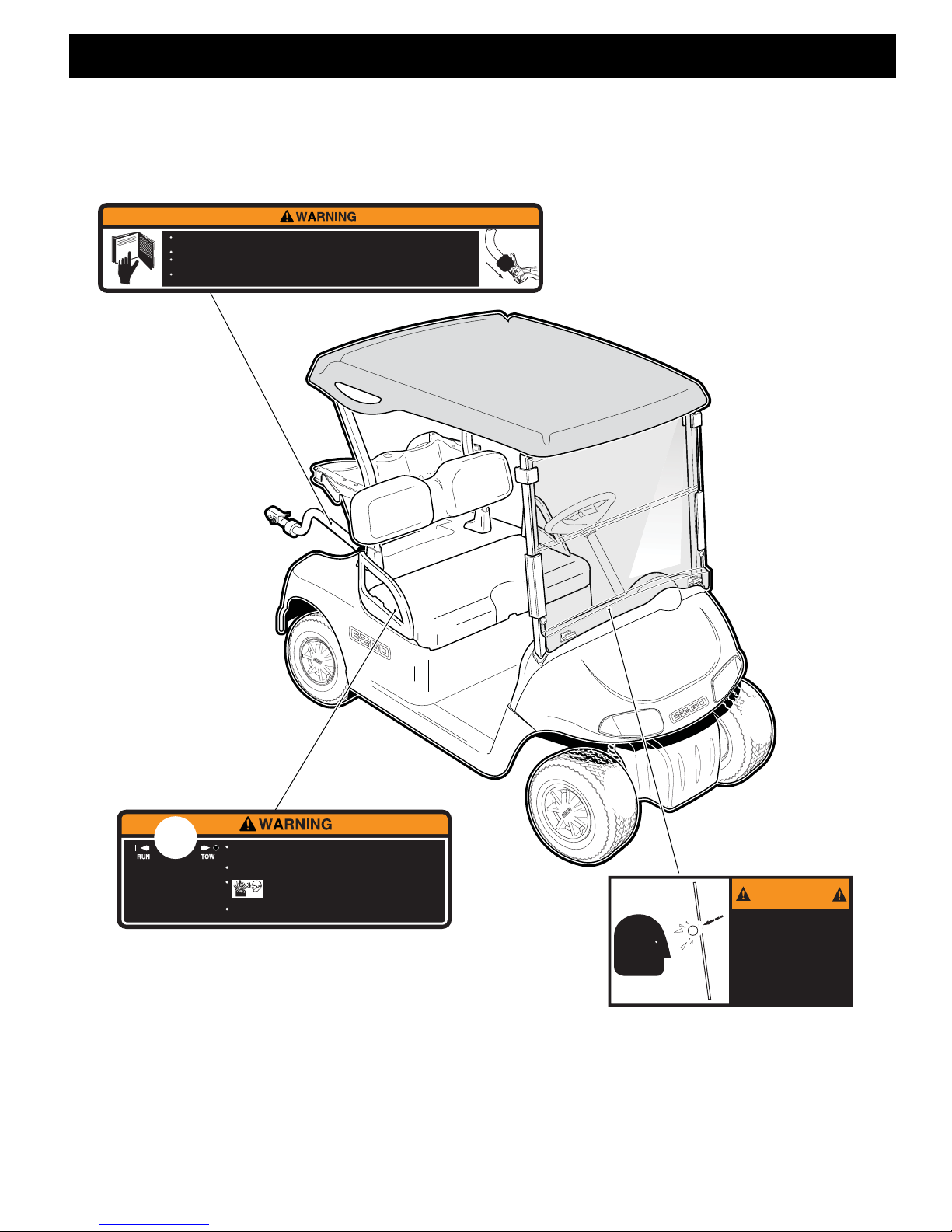
BEFORE OPERATING
READ all warning labels and the owner’s manual. Contact an authorized E-Z-GO dealer or visit
www.ezgo.com for a replacement manual.
This vehicle is equipped for personal use in most communities. However, state law or local rules may
require additional equipment in your community.
SAFE OPERATION
Turn key to “ON” - select “forward” or “reverse” - release the parking brake (Gas vehicle only) - then slowly
depress accelerator pedal.
Always bring the vehicle to a complete stop BEFORE shifting the direction selector.
Operate from the driver’s seat ONLY.
PARKING
ALWAYS fully engage the parking brake and remove the key BEFORE leaving the vehicle. In an electric
vehicle set the direction selector to “neutral” and in a gasoline vehicle set the selector to “forward”.
MAINTENANCE
This vehicle requires regularly scheduled maintenance (see owner’s manual). ONLY qualified
personnel should service this vehicle.
Read all of this manual to become thoroughly familiar with this vehicle. Pay particular attention to all Notes, Cautions and Warnings.
B
Except where PERMITTED BY LAW:
AVOID FALLS from the vehicle:
Reduce the RISK OF ACCIDENTS:
This vehicle is NOT A TOY:
DO NOT OVERLOAD this vehicle:
DO NOT MODIFY this vehicle:
Except where PERMITTED BY LAW:
Reduce the RISK OF ACCIDENTS:
DO NOT OVERLOAD this vehicle:
AVOID FALLS from the vehicle:
STARTING the vehicle:
Drive with CAUTION:
STOPPING the vehicle:
PARKING the vehicle:
Failure to follow these instructions can result in SERIOUS INJURY or DEATH
NEVER drive on public roads. Drivers must possess a valid drivers license in accordance with local state law.
Do not start moving until all occupants are PROPERLY SEATED and HOLDING ON. KEEP entire body INSIDE VEHICLE while moving.
Always DRIVE SLOWLY in congested areas, on wet or loose terrain, and when backing up. DRIVE SLOWLY when turning and
ALWAYS drive straight up and down slopes. Do not coast, use BRAKE when going down a slope. NEVER drive this vehicle under the influence
of drugs or alcohol.
Drive responsibly. NEVER leave children unattended or allow children to play on the vehicle. NEVER leave the key in the vehicle when parked.
NEVER carry more than 2 occupants on each bench seat. Do not exceed vehicle WEIGHT CAPACITY (see Owner’s Manual).
NEVER alter this vehicle to increase travel speeds above factory specifications. ONLY authorized E-Z-GO dealers should alter the vehicle using
approved parts. Alterations not approved or tested by E-Z-GO can create unsafe conditions and increase your chance of having an accident.
AVOID sudden stops.
608528
Failure to follow these instructions can result in SERIOUS INJURY or DEATH
To be operated by persons with valid drivers license, in accordance with state requirements. Operate from Driver’s side only.
For non-road use, and in designated areas only. Do not operate under the influence of drugs or alcohol.
All occupants must be fully seated, keep entire body inside vehicle and hold on while vehicle is in motion.
Apply service brake , move direction selector to desired position and accelerate smoothly. On Gas Vehicle, direction selector is
the F-N-R. On Electric vehicle, direction selector is the key switch.
Maximum vehicle payload is 800 lbs. (363 kg) including a maximum of 2 persons, options, and accessories.
Drive slowly straight up and down slopes and in turns. Use care in reverse, congested areas, and wet or loose terrain.
To stop, release accelerator pedal and apply service brake.
Before leaving vehicle , turn key ‘OFF’. On Gas vehicle, move the direction selector to “FORWARD” and engage park brake.
608522 FLEET VEHICLES
608528
608522
Vehicle can MOVE SUDDENLY when brake
is released causing SERIOUS INJURY or DEATH
Vehicle can roll, even on fairly level ground.
Turn key switch to ‘OFF’ before releasing brake.
Manual brake lever will release the park brake and can result in the
vehicle moving unexpectedly.
608524
Page x
608524
Owner’s Guide
BEFORE OPERATING
READ all warning labels and the owner’s manual. Contact an authorized E-Z-GO dealer or visit
www.ezgo.com for a replacement manual.
This vehicle is equipped for personal use in most communities. However, state law or local rules may
require additional equipment in your community.
SAFE OPERATION
Turn key to “ON” - select “forward” or “reverse” - release the parking brake (Gas vehicle only) - then slowly
depress accelerator pedal.
Always bring the vehicle to a complete stop BEFORE shifting the direction selector.
Operate from the driver’s seat ONLY.
PARKING
ALWAYS fully engage the parking brake and remove the key BEFORE leaving the vehicle. In an electric
vehicle set the direction selector to “neutral” and in a gasoline vehicle set the selector to “forward”.
MAINTENANCE
This vehicle requires regularly scheduled maintenance (see owner’s manual). ONLY qualified
personnel should service this vehicle.
OPERATING INSTRUCTIONS
608529
608529
LABELS & PICTOGRAMS
WARNING
Windshields do not
provide protection
from golf balls or
other flying objects.
608523
DO NOT alter or tamper with this unit. Unauthorized modifications can result in DO NOT alter or tamper with this unit. Unauthorized modifications can result in
SERIOUS INJURY or damage to the vehicle and will void the warranty.SERIOUS INJURY or damage to the vehicle and will void the warranty.
TOWING - Always select ‘TOW’
position before towing
WAIT 30 seconds after reconnecting batteries BEFORE turning key switch to WAIT 30 seconds after reconnecting batteries BEFORE turning key switch to
‘REVERSE’, ‘FORWARD’ or ‘NEUTRAL’ positions.‘REVERSE’, ‘FORWARD’ or ‘NEUTRAL’ positions.
608523
To disable electrical system, turn key switch to ‘OFF’ and remove battery wires.To disable electrical system, turn key switch to ‘OFF’ and remove battery wires.
ALWAYS turn key to ‘OFF’ before disconnecting or reconnecting ALWAYS turn key to ‘OFF’ before disconnecting or reconnecting
battery wires. ELECTRICAL ARC or BATTERY EXPLOSION can battery wires. ELECTRICAL ARC or BATTERY EXPLOSION can
occur if key is not in the ‘OFF’ position.occur if key is not in the ‘OFF’ position.
This device is ONLY to be used for towing E-Z-GO vehicles. NEVER tow other vehicles or equipment.This device is ONLY to be used for towing E-Z-GO vehicles. NEVER tow other vehicles or equipment.
READ Owner’s Manual before towingREAD Owner’s Manual before towing.
NEVER tow more than 3 vehicles at one time. DRIVE SLOWLY and never tow vehicle over rough or NEVER tow more than 3 vehicles at one time. DRIVE SLOWLY and never tow vehicle over rough or
unsafe terrain. NO RIDERS in towed carsunsafe terrain. NO RIDERS in towed cars. .
MONTHLY INSPECTION: tow bar pins, attaching hardware, and front frame attachment of towed cars.MONTHLY INSPECTION: tow bar pins, attaching hardware, and front frame attachment of towed cars.
Replace worn or damaged parts. CHECK alignment of wheels on towed carsReplace worn or damaged parts. CHECK alignment of wheels on towed cars. .
FULLY ENGAGE coupling. Rubber latch-stop must be under latch release lever. FULLY ENGAGE coupling. Rubber latch-stop must be under latch release lever.
608525
608525
EGWHL14
Read all of this manual to become thoroughly familiar with this vehicle. Pay particular attention to all Notes, Cautions and Warnings.
B
B
Owner’s Guide
Page xi
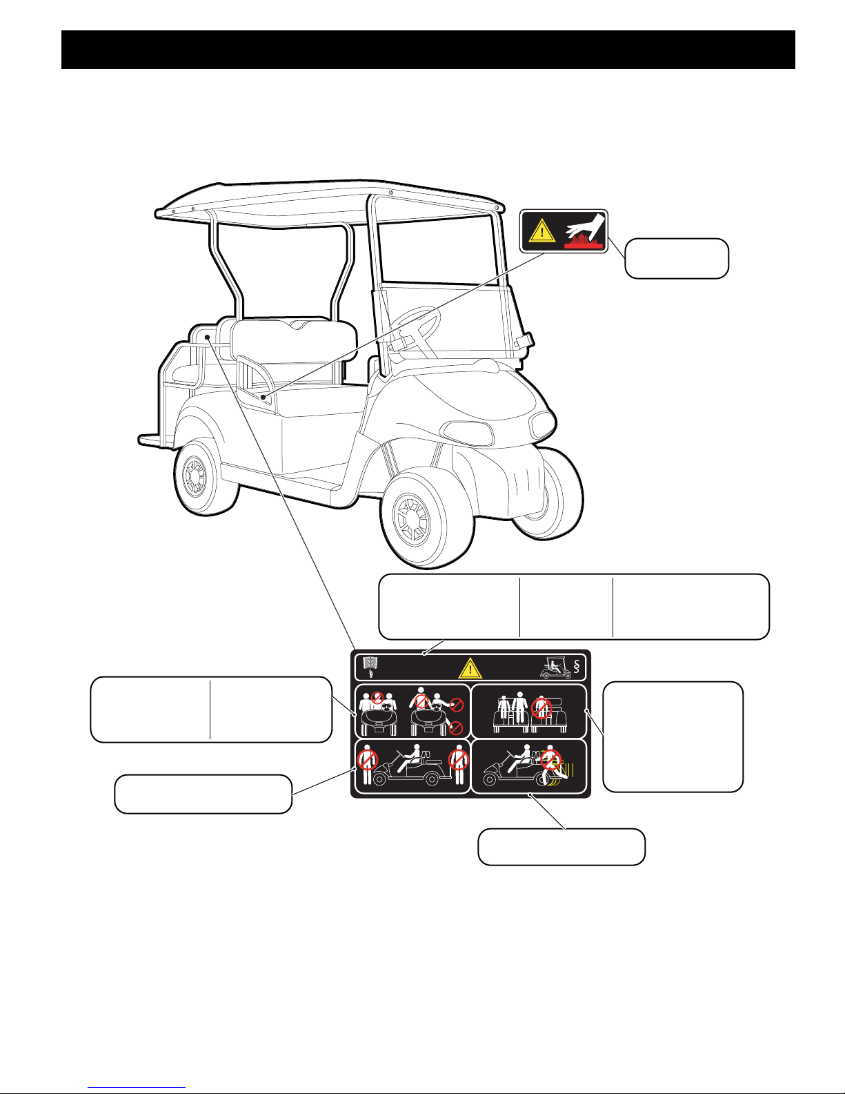
LABELS & PICTOGRAMS
74074-G01
!
74074G01
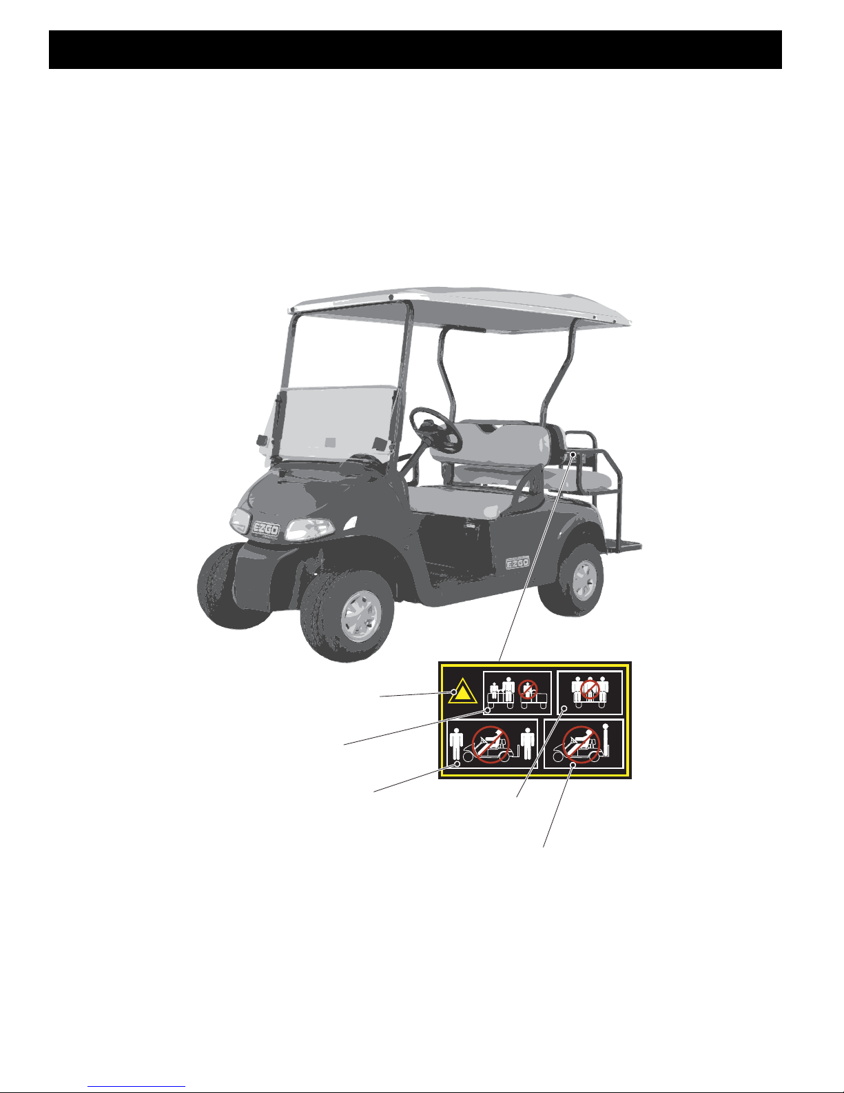
WARNING
DO NOT leave a child
unattended on the seat
while vehicle is moving
DO NOT opperate vehicle
if people are in front of or
behind the vehicle
DO NOT opperate
vehicle with occupants
standing
No more than
2 occupants
per seat.
Read all of this manual to become thoroughly familiar with this vehicle. Pay particular attention to all Notes, Cautions and Warnings.
B
Page xii
Owner’s Guide

LABELS & PICTOGRAMS
Read all of this manual to become thoroughly familiar with this vehicle. Pay particular attention to all Notes, Cautions and Warnings.
Notes:
Owner’s Guide
Page xiii
LABELS & PICTOGRAMS
608701 CE VEHICLES
608817
608701
R
F
ON
OFF
I
O
ON
N
F
R
OFF
O
< 14° 25%
< 14° 25%
ON
OFF
I
O
R F
F
R
OFF
O
ON
N
ON
N
F
R
OFF
O
R
F
ON
OFF
I
O
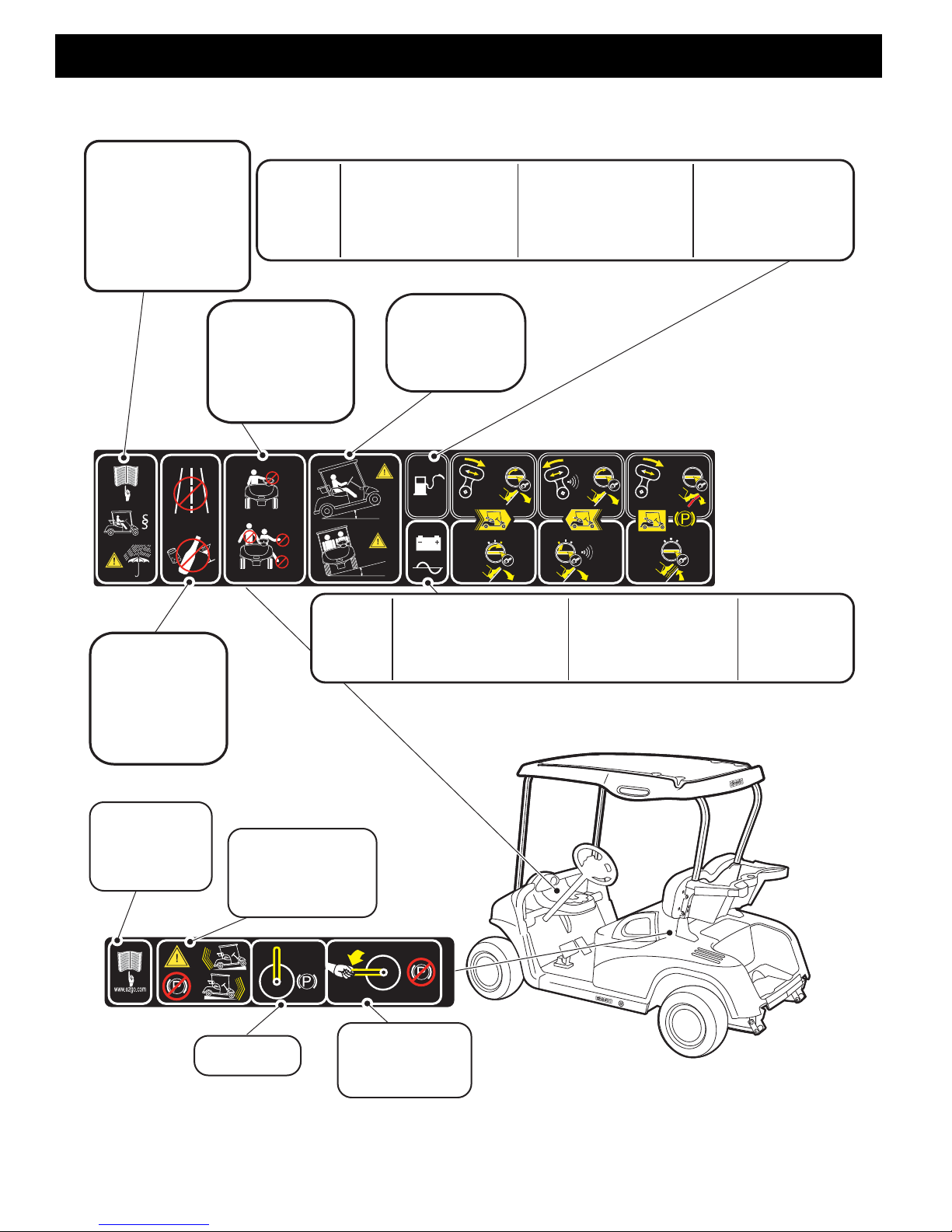
608817
MAXIMUM RAMP
OR HILL
MAXIMUM CROSS
RAMP OR HILL
OPERATE FROM
DRIVER SIDE ONLY
DO NOT STAND UP
AND KEEP ENTIRE
BODY INSIDE
VEHICLE
DO NOT DRIVE
ON HIGHWAY
DO NOT OPERATE
IF USING DRUGS
OR ALCOHOL
READ THE MANUAL
OPERATE ACCORDING
TO LOCAL LAWS AND
REGULATIONS
USE CAUTION IN
BAD WEATHER
FORWARD OPERATION
* TURN KEY TO ‘ON’
* MOVE DIRECTION
SELECTOR TO ‘F’
* PRESS ACCELERATOR
PEDAL GENTLY
REVERSE OPERATION
* TURN KEY TO ‘ON’
* MOVE DIRECTION
SELECTOR TO ‘R’
* PRESS ACCELERATOR
PEDAL GENTLTY
PARK VEHICLE
* MOVE DIRECTION
SELECTOR TO ‘F’
* TURN KEY TO ‘OFF’
* APPLY PARKING
BRAKE
GASOLINE
VEHICLES
FORWARD OPERATION
* TURN KEY TO ‘F’
* PRESS ACCELERATOR
PEDAL GENTLY
REVERSE OPERATION
* TURN KEY TO ‘R’
* GENTLY PRESS
ACCELERATOR
PEDAL
PARK VEHICLE
* TURN KEY
TO ‘OFF’
ELECTRIC
VEHICLES
HANDLE UP
BRAKE IS ON
PUSH HANDLE
DOWN AND
HOLD TO
RELEASE BRAKE
READ THE
MANUAL
REPLACEMENT
AVAILABLE AT
www.ezgo.com
WARNING: WHEN
BRAKE IS OFF
VEHICLE MAY MOVE
WHEN STOPPED
ON A SLOPE
Read all of this manual to become thoroughly familiar with this vehicle. Pay particular attention to all Notes, Cautions and Warnings.
B
Page xiv
Owner’s Guide
LABELS & PICTOGRAMS
608819
R
F
NO
FFO
I
O
NO
N
F
R
FFO
O
NO
F
FO
I
O
R
F
F
R
FFO
O
P
NO
N
NO
N
F
R
FFO
O
R
F
NO
FFO
I
O
www.ezgo.com
www.ezgo.com
608819
WARNING READ THE MANUAL
REPLACEMENT
IS AVAILABLE AT
www.ezgo.com
READ ALL
LABELS
OPERATE
FROM
DRIVER
SIDE
ONLY
OPERATE
ACCORDING
TO LOCAL
LAWS AND
REGULATIONS
MAINTAIN
ACCORDING
TO SERVICE &
REPAIR MANUAL
AVAILABLE AT
www.ezgo.com
FORWARD OPERATION
* TURN KEY TO ‘ON’
* MOVE DIRECTION
SELECTOR TO ‘F’
* PRESS ACCELERATOR
PEDAL GENTLY
REVERSE OPERATION
* TURN KEY TO ‘ON’
* MOVE DIRECTION
SELECTOR TO ‘R’
* PRESS ACCELERATOR
PEDAL GENTLTY
PARK VEHICLE
* MOVE DIRECTION
SELECTOR TO ‘F’
* TURN KEY TO ‘OFF’
* APPLY PARKING BRAKE
GASOLINE
VEHICLES
FORWARD OPERATION
* TURN KEY TO ‘F’
* PRESS ACCELERATOR
PEDAL GENTLY
REVERSE OPERATION
* TURN KEY TO ‘R’
* PRESS ACCELERATOR
PEDAL GENTLY
PARK VEHICLE
* TURN KEY TO ‘OFF’
ELECTRIC
VEHICLES
Read all of this manual to become thoroughly familiar with this vehicle. Pay particular attention to all Notes, Cautions and Warnings.
B
B
Owner’s Guide
Page xv
LABELS & PICTOGRAMS
Read all of this manual to become thoroughly familiar with this vehicle. Pay particular attention to all Notes, Cautions and Warnings.
B
DO NOT TOW MORE THAN 3 VEHICLES
DO NOT DRIVE IN REVERSE WHEN TOWING VEHICLES
NO PASSENGERS IN TOWED VEHICLES
DO NOT TOW VEHICLES OVER UNEVEN TERRAIN
READ THE
MANUAL
REPLACEMENT
AVAILABLE AT
www.ezgo.com
WARNING
DO NOT
DRIVE
FAST
WARNING INSPECT TOW BAR
SYSTEM EVERY 30 DAYS
WARNING
ENGAGE
LOCKING
COLLAR
608525
608821
TOW BAR OPERATION
* PULL LOCKING COLLAR AWAY
FROM LATCH AND PRESS ON
LATCH TAB TO OPEN
* PLACE LATCH OVER FRONT
TOWING BRACKET
* CLOSE LATCH AND MOVE
LOCKING COLLAR UNDER
LATCH TAB
WARNING: ATTACH TOW BAR BEFORE
TURNING KEY SWITCH TO ‘TOW’
ON
N
F
R
O
OFF
KEEP
HANDS
OUT
READ THE
MANUAL
REPLACEMENT
AVAILABLE AT
www.ezgo.com
TO REDUCE POSSIBILITY OF
BATTERY EXPLOSION TURN
KEY TO ‘OFF’ BEFORE
DISCONNECTING OR CONNECTING
BATTERY WIRES
608769
Page xvi
Owner’s Guide
LABELS & PICTOGRAMS
608537
:
608820
608820
www.ezgo.com
READ THE MANUAL
REPLACEMENT
AVAILABLE AT
www.ezgo.com
WARNING OPERATE ACCORDING
TO LOCAL LAWS AND
REGULATIONS
NO MORE THAN 2
OCCUPANTS IN
EACH SEAT
DO NOT STAND UP
AND KEEP ENTIRE
BODY INSIDE
VEHICLE
DO NOT STAND IN FRONT
OF OR BEHIND VEHICLE
CHILDREN MUST BE
ACCOMPANIED BY
AN ADULT
DO NOT ALLOW
CHILDREN TO
RIDE ALONE
DO NOT GET ON OR OFF
A MOVING VEHICLE
WARNING
HOT SURFACE
608823
Read all of this manual to become thoroughly familiar with this vehicle. Pay particular attention to all Notes, Cautions and Warnings.
B
B
Owner’s Guide
Page xvii

LABELS & PICTOGRAMS
Read all of this manual to become thoroughly familiar with this vehicle. Pay particular attention to all Notes, Cautions and Warnings.
Notes:
Page xviii
Owner’s Guide
OPERATION AND SERVICE INFORMATION
Serial Number
Serial Number
Serial Number
Read all of this manual to become thoroughly familiar with this vehicle. Pay particular attention to all Notes, Cautions and Warnings.
Thank you for purchasing this vehicle. Before driving the
vehicle, we ask you to spend some time reading this
Owner’s Guide. This guide contains the information that
will assist you in maintaining this highly reliable vehicle.
Some illustrations may show items that are optional for
your vehicle. This guide covers the operation of several
vehicles, therefore, some illustrations may not represent
your vehicle. Physical differences in controls will be illustrated.
This vehicle has been designed and manufactured as a
‘World Vehicle’. Some countries have individual requirements to comply with their specifications; therefore,
some sections may not apply in your country.
Most of the service procedures in this guide can be accomplished using common automotive hand tools. Contact your service representative on servicing the vehicle
in accordance with the Periodic Service Schedule.
Service Parts Manuals as well as Repair and Service
Manuals are available from a local Distributor, an authorized Branch or the Service Parts Department. When
ordering parts or requesting information for your vehicle,
provide the vehicle model, serial number and manufacture date code.
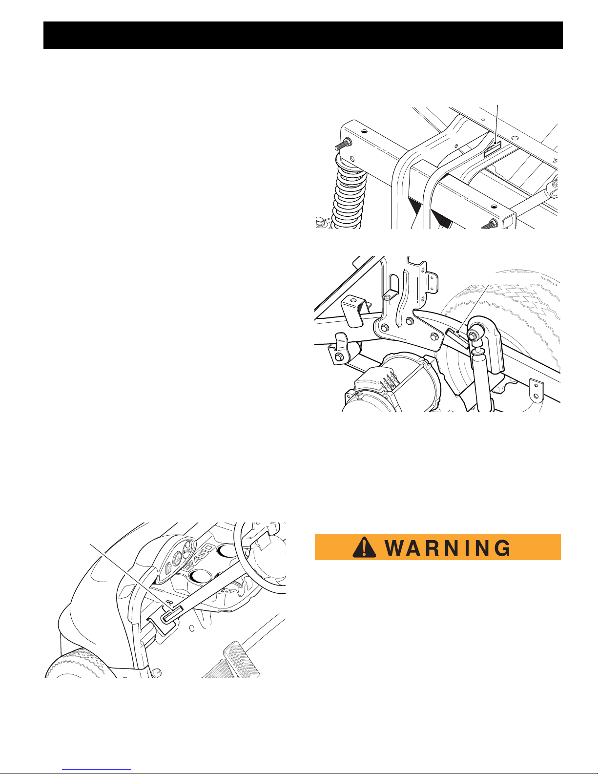
Fig. 2 Serial Number on Front Frame
B
B
SERIAL NUMBER LOCATION
Three serial number and manufacture date code labels
are on the vehicle. One is placed on the steering column
(Ref. Fig. 1), the second is located on the frame member under the front splash shield on the driver side (Ref.
Fig. 2) and the third is located on the passenger side
frame rail at the rear of the vehicle (Ref. Fig. 3).
In order to obtain correct components for the vehicle,
the manufacture date code, serial number and vehicle
model must be provided when ordering service parts.
Fig. 1 Serial Number Location on Steering Column
Fig. 3 Serial Number on Rear Frame
BEFORE INITIAL USE
Read, understand and follow the safety label on the instrument panel. Be sure you understand how to operate
the vehicle and its equipment as well as how to use it
safely. Maintaining good performance dep ends to a
large extent on the operator.
Hydrogen gas is generated as a natural part of
the lead acid battery charging process. A 4%
concentration of hydrogen gas is explosive
and could cause severe injury or death. Charging must take place in an area that is adequately ventilated (minimum of 5 air
exchanges per hour).
To reduce the chance of battery explosion that
could result in severe injury or death, never
smoke around or charge batteries in an area
that has open flame or electrical equipment
Owner’s Guide
Page 1
OPERATION AND SERVICE INFORMATION
DANGER
Keep cooling fins clean and free of dirt and debris
NEMA 15 - 5R Grounded AC Receptacle
110 - 120 VAC. Dedicated 15 AMP Circuit
Locations outside the US and Canada: Reference
appropriate local electrical code and charger manufacturer recommendations for AC power requirements
Read all of this manual to become thoroughly familiar with this vehicle. Pay particular attention to all Notes, Cautions and Warnings.
that could cause an electrical arc.
B
Before a new vehicle is put into operation, the items
shown in the INITIAL SERVICE CHART must be performed (Ref. Fig. 4).
The vehicle batteries must be fully charged before initial
use.
Check for correct tire inflation. See GENERAL SPECIFICATIONS.
Determine and record the braking distance required to
stop the vehicle for future brake performance tests.
Remove the protective clear plastic from the seat bottom and back rest before placing the vehicle in service
.
ITEM SERVICE OPERATION
Batteries Charge batteries
Seats Remove protective plastic covering
Brakes Check operation
Establish acceptable stopping distance
Tires Check air pressure (see SPECIFICATIONS)
Portable Remove from vehicle and properly mount
Charger
Fig. 4 Initial Service Chart
PORTABLE CHARGER
PORTABLE CHARGER INSTALLATION
Use charger ONLY on 48 volt battery systems.
Other usage may cause personal injury and
damage. Lead acid batteries may generate
explosive hydrogen gas during normal operation. Keep sparks, flames, and smoking materials away from batteries. Provide adequate
ventilation during charging. Never charge a
frozen battery. Study all battery manufacturers’
specific precautions such as recommended
rates of charge and removing or not removing
cell caps while charging.
is required to reduce risk of electric shock – do
not use ground adapters or modify plug. Do
not touch uninsulated portion of output connector or uninsulated battery terminal. Disconnect the DC supply before making or breaking
the connections to the battery while charging.
Do not open or disassemble charger. Do not
operate charger if the AC supply cord is damaged or if the charger has received a sharp
blow, been dropped, or otherwise damaged in
any way – refer all repair work to qualified personnel. Not for use by children.
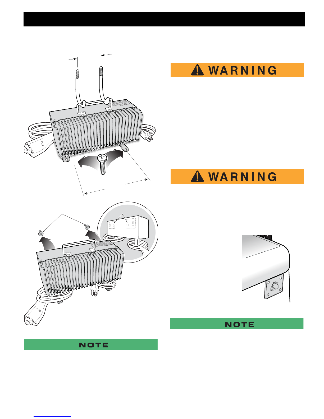
Portable chargers are shipped with the vehicles. Prior to
vehicle or charger operation, the charger must be removed and mounted on a platform or wall above the
ground to permit maximum air flow around and underneath the charger. A dedicated circuit is required for
the charger. Refer to the charger manual for appropriate circuit protection. For optimum performance and
shortest charge times, place the charger in an area with
adequate ventilation. The charger should also be placed
in an area that will be relatively free of dirt, mud, or d ust
since accumulations within the fins of the charger will
reduce their heat-dissipating qualities. Optimal cooling
also occurs when the charger is placed on a horizontal
surface with the fins vertical. More airflow from below
the charger will help cool the fins, so placement above
open areas or areas with cut-outs for airflow is desirable. If the charger is operated in an outdoor location,
rain and sun protection must be provided. The charger
may get hot during operation and must be placed such
that risk of contact by people is reduced. The charger
may be mounted on a wall or shelf using #10-M5
screws. The charger’s status display must be visible to
the user.
Risk of electric shock. Connect charger power
cord to an outlet that has been properly
installed and grounded in accordance with all
local codes and ordinances. A grounded outlet
Page 2
Fig. 5 Charger Installation
Owner’s Guide
OPERATION AND SERVICE INFORMATION
7.25"
(18.5cm)
3.2"
(8.1cm)
Mounting Slots
Mounting Screws
Read all of this manual to become thoroughly familiar with this vehicle. Pay particular attention to all Notes, Cautions and Warnings.
driving over or catching the cord on the vehicle when driving
away.
An ungrounded electrical device may become
a physical hazard that could result in an electrical shock or electrocution.
USING THE CHARGER
The charger may remain plugged into the AC outlet
when not in use. To charge the vehicle refer to the instruction labels on the charger. Insert the polarized DC
plug completely into the vehicle receptacle. The charger
will automatically start a few seconds after the plug is in
place. The charger will automatically stop when the batteries are fully charged and the DC plug can be removed to permit use of the vehicle.
B
B
Fig. 6 Charger Mounting
To prevent a physical hazard that could result
in an electrical shock or electrocution, be sure
that the charger plug is not damaged and is
inserted into a grounded receptacle.
The power (AC) cord is equipped with a
grounded plug. Do not attempt to pull out, cut
or bend the ground post.
The charging (DC) cord is
equipped with a polarized
connector that fits into a
matching receptacle on the
vehicle. The receptacle is located on the driver side of
the vehicle just below the
seat bottom.
Fig. 7 Charger Receptacle
If vehicle is to be charged w it h a no n E- Z-GO c h ar ger, refer to
the instructions supplied with the charger.
Looping the DC cord through the steering wheel when charging serves as a good reminder to store the cord out of the way
when finished with charging. The DC plug can be damaged by
UNDERSTANDING THE CHARGER
Plugging the charger into the vehicle’s charger receptacle will lock the vehicle out of operation. When the
charger is plugged into the vehicle’s charger receptacle,
Owner’s Guide
Page 3

OPERATION AND SERVICE INFORMATION
Read all of this manual to become thoroughly familiar with this vehicle. Pay particular attention to all Notes, Cautions and Warnings.
the charger will automatically turn on and the charger ’s
LED and the vehicle receptacle’s LED will start flashing
B
GREEN to indicate the batteries are charging.
Once a minimum battery voltage of 2 volts per cell (Vpc)
is reached, the charger’s output current will change from
a full current charge to the trickle rated charging current.
The length of charge time will vary by how depleted the
batteries are, the input AC voltage, and/or charger ambient temperatures. The charger’s LED will give a SHORT
flash if the charge is less than 80% and a LONG flash if
the charge is greater than 80%. If the charger’s LED is a
steady GREEN the batteries are fully charged and the
charger may be unplugged, although not necessary.
The charger may be left plugged in for long periods of
time to maintain the batteries charge level.
If a fault occurred anytime during the charging the
charger’s LED will quickly flash RED. The specific fault
is indicated by the number of RED flashes that occur,
there will be a pause and then the flashes will repeat
again. There are several possible conditions that will
generate errors. Some errors will require human intervention to first resolve the problem and then reset the
charger by unplugging the DC cord from the vehicle.
If the AC voltage is interrupted and restored, the charger
will turn back on automatically.
LED OPERATION CODES:
SHORT GREEN FLASH = less than 80% charged
LONG GREEN FLASH = more than 80% charged
SOLID GREEN = 100% charged
RED FLASH = fault code
FOUR RED FLASHES: Four flashes, a pause and
then again four flashes and a pause - Battery
Fault: Charge time exceeded. This indicates a
problem with the battery pack voltage not reaching the required nominal level within the maximum time allowed.
SIX RED FLASHES: Six flashes, a pause and
then again six flashes and a pause - Charger
Fault: An internal fault has been detected. If this
fault is displayed again after unplugging the
charger’s DC power cord and plugging it back in ,
the charger must be taken to a qualified service
center.
MAINTENANCE INSTRUCTIONS
1. For flooded lead-acid batteries, regularly check the
water levels of each battery cell after charging and
add distilled water as required to the level specified by
the battery manufacturer. Follow the safety instructions recommended by the battery manufacturer.
2. Make sure the charger connections to the battery terminals are tight and clean. Check for any deform a tions or cracks in the plastic parts. Check the charger
harness for chaffing and rubbin g. Inspe ct all wiring for
fraying, loose terminals, chaffing, corrosion or deterioration of the insulation.
3. Keep the cooling fins free of dirt and debris, do not expose the charger to oil, dirt, mud or to direct heavy water spray when cleaning equipment.
4. Inspect the plug of the battery charger and the vehicle
receptacle housing for dirt or debris. Clean the DC
connector monthly or more often if needed.
LED FAULT CODES:
RED FLASH: Light turns on briefly, but does not
flash after that - check for valid AC voltage.
ONE RED FLASH: One flash, a pause and then
again one flash and a pause - Charge Enable
Fault: poor contact in the DC connector or dirty
contacts or Battery Temperature Fault: battery
temperature is greater than 122° F (50° C) or less
than 14° F (-10° C).
TWO RED FLASHES: Two flashes, a pause and
then again two flashes and a pause - Battery Voltage Fault: Battery pack is less than 36.0 Volts or
more than 67.2 Volts. Battery pack is too discharged or over charged for the charger to work.
THREE RED FLASHES: Three flashes, a pause
and then again three flashes and a pause - Battery Charge Time-out: Charge time exceeded 24
hours. This may indicate a problem with the battery pack or that the charger output current was
severely reduced due to high ambient temperatures.
Page 4
If vehicle is to be charged with a non E-Z-GO charger, refer to
the instructions supplied with the charger.
Owner’s Guide
OPERATION AND SERVICE INFORMATION
608769
F
R
OFF
O
ON
N
Read all of this manual to become thoroughly familiar with this vehicle. Pay particular attention to all Notes, Cautions and Warnings.
B
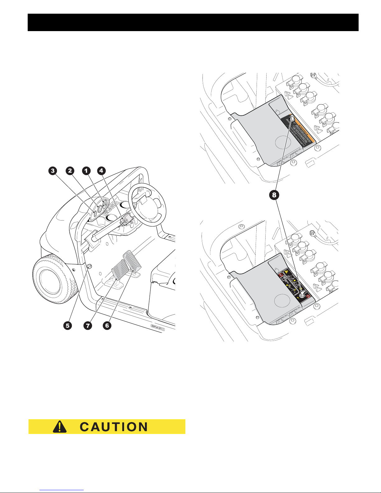
CONTROLS AND INDICATORS
Vehicle controls and indicators consist of:
1. Key Switch / Direction Selector
2. State Of Charge Meter (optional)
3. Head Light Switch (optional)
4. Turn Signal Switch (optional)
5. Horn Button (optional)
6. Accelerator Pedal
7. Service Brake Pedal
8. Run/Tow Switch
l
vehicle must be stopped before moving the key switch/
direction selector.
B
Fig. 8 Operator Controls & Gauges
KEY SWITCH/DIRECTION SELECTOR
Located on the dash panel, the key switch/direction selector (1) enables the electrical system of the vehicle to
be turned on and off by turning the key; it also functions
as the direction selector for forward, neutral or reverse.
To prevent inadvertent operation of the vehicle when left
unattended, the key should be turned to the ‘OFF’ position and removed.
To reduce the possibility of component damage, the
STATE OF CHARGE METER (OPTIONAL
EQUIPMENT)
If the vehicle is equipped with a state of charge meter
(2), it is located in the dash panel to the left of the key
switch (1) (Ref. Fig. 8). The state of charge meter indicates the amount of usable power in the batteries. The
state of charge meter on the electric vehicle shows the
condition of the battery pack with F indicating a full
charge on the battery pack and E indicating the battery
pack needs to be charged.
Owner’s Guide
Fig. 9 Run/Tow Switch
Page 5
OPERATION AND SERVICE INFORMATION
Read all of this manual to become thoroughly familiar with this vehicle. Pay particular attention to all Notes, Cautions and Warnings.
HEADLIGHT SWITCH (OPTIONAL EQUIPMENT)
B
If the vehicle is equipped with headlights, the ON/OFF
switch (3) is located on the instrument panel to the left
of the key switch (1) (Ref. Fig. 8).
Use of the manual brake release lever will
release the park brake and may cause the
vehicle to move unexpectedly.
TURN SIGNAL SWITCH (OPTIONAL EQUIPMENT)
If the vehicle is equipped with turn signals, the switch (4)
is mounted on the steering column (Ref. Fig. 8).
HORN (OPTIONAL EQUIPMENT)
If the vehicle is equipped with a horn, the horn button (5)
is located on the driver’s side floorboard; depressing the
button will sound the vehicle’s horn (Ref. Fig. 8).
If the vehicle is equipped with factory installed custom accessories, some accessories remain operational with the key
switch in the ‘OFF’ position.
ACCELERATOR & BRAKE PEDALS
With the key switch in the ’F’ or ’R’ position, depressing
the accelerator pedal (6) starts the motor and will move
the vehicle in the direction indicated on the key switch/
direction selector. This vehicle is equipped with a motor
brake; when the accelerator pedal is released, the motor
will stop. To stop the vehicle more quickly , depress the
service brake pedal (7)(Ref. Fig. 8).
PARKING BRAKE
This vehicle is equipped with an automatic parking
brake; when the vehicle is stopped the parking brake is
automatically set. The parking brake is released when
the key switch/direction selector is in forward (’F’) or reverse (’R’) and the accelerator is depressed. The parking brake is also released when the run/tow switch is
placed in the ’TOW’ or (on CE vehicles) position
with the key switch turned to neutral (’N’).
In the event of a controller failure the parking brake can
be released using the Manual Release Lever located
under the seat on the end of the AC motor on the driver
side of the vehicle. To use this lever, turn the key switch
to ’OFF’ then move the manual release lever in a
counter clockwise direction and hold in down while moving the vehicle. Once the handle is released the parking
brake is activated again.
RUN/TOW SWITCH
Before attempting to tow the vehicle, turn the key
switch to ’N’ and move the Run/Tow switch to the
‘TOW’ position. Failure to do so will damage the controller or motor.
The RUN/TOW switch should always be returned to th e ’RUN’
or (on CE vehicles) position after towing the vehicle. If
the switch is left in the ’TOW’ or (on CE vehicles) position
for an extended period of time it will drain the batteries.
The run/tow switch (8) is located under the seat on the
passenger side of the vehicle (Ref. Fig. 9).
With the switch in the ‘TOW’ or (on CE vehicles)
position and the key in ’N’:
• the electronic parking brake is deactivated, which
allows the vehicle to be towed or roll freely, except
in the event of a controller failure
• the service brake is still active
• the reverse warning beeper is deactivated
With the switch in ‘RUN’ or (on CE vehicles) position:
• the electronic parking brake is deactivated and the
reverse warning beeper features are activated
OPERATING THE VEHICLE
Improper use of the vehicle or the lack of proper maintenance may result in damage or decreased performance.
Read and understand the following warnings before
attempting to operate the vehicle.
Page 6
To reduce the possibility of severe injury or
Owner’s Guide

OPERATION AND SERVICE INFORMATION
Read all of this manual to become thoroughly familiar with this vehicle. Pay particular attention to all Notes, Cautions and Warnings.
B
death resulting from loss of vehicle control, the
following warnings must be observed:
When driving vehicle, consider the terrain, traffic conditions and the environmental factors
which effect the terrain and the ability to control the vehicle.
Use extra care and reduced speed when driving on poor surfaces, such as loose dirt, wet
grass, gravel, etc.
Stay in designated areas and avoid extremely
rough terrain.
Maintain a safe speed when driving down hill.
Use the service brake to reduce speed when
traveling down an incline. A sudden stop or
change of direction may result in loss of control.
Slow down before and during turns. All turns
should be made at reduced speed.
Never drive vehicle up, down, or across an
incline that exceeds 14° (25% grade).
REGENERATIVE BRAKING
B
To prevent the possibility of loss of control that
could cause severe injury or death, use service brake to reduce speed.
This vehicle is equipped with a regenerative motor co ntrol system.
Example: If both of the following events occur:
a) the vehicle is being driven down a slope
b) the driver attempts to exceed the specified top
speed with the accelerator pedal depressed or
released
the regenerative braking will limit the speed of the vehicle to the specified top speed. When the regenerative
braking system is activated by this sequence of events,
the motor generates power that is returned to the ba tteries.
When the vehicle speed is reduced below the maximum
by using the service brake, the speed will not increase
unless the throttle is increased. When the brake pedal is
released the vehicle will slow down as it does with pedal
up braking.
To reduce the possibility of severe injury or
death resulting from improper vehicle operation, the following warnings must be observed:
Refer to GENERAL SPECIFICATIONS for
seating capacity.
To prevent inadvertent movement when the
vehicle is to be left unattended, turn key to
‘OFF’ position and remove the key.
Make sure that the direction selector is in correct position before attempting to start the
vehicle.
Always bring the vehicle to a complete stop
before shifting the direction selector.
Check the area behind the vehicle before
operating in reverse.
All occupants must be seated. Keep entire
body inside vehicle and hold on while vehicle
is in motion.
PEDAL-UP BRAKING
Pedal-up braking is regenerative braking that occurs
when the accelerator pedal is released while the vehicle
is moving.
Example: If both of the following events occur:
a) the vehicle is being driven down a slope
b) the accelerator pedal is released
the pedal-up braking will slow the vehicle until the vehicle stops, or the accelerator pedal is applied. When
pedal-up braking system is activated by this sequence
of events, the motor generates power that is returned to
the batteries.
HIGH PEDAL DISABLE FEATURE
High pedal disable prevents acceleration if the key is
turned on while the accelerator is depressed.
STARTING AND DRIVING
All vehicles are equipped with an interlock system that
disables the controller and prevents the vehicle from being operated or towed while the charger is connected.
Remove the charger plug from the vehicle receptacle
and properly store the cable prior to moving the vehicle.
Owner’s Guide
Page 7
OPERATION AND SERVICE INFORMATION
Read all of this manual to become thoroughly familiar with this vehicle. Pay particular attention to all Notes, Cautions and Warnings.
To operate the vehicle:
B
• Place the key in the key switch and turn it to the
‘ON’/’N’ position.
• Move the direction selector to the direction
desired.
• Slowly depress the accelerator pedal to start the
motor.
• When the accelerator pedal is released, the motor
controls the deceleration. To stop the vehicle more
quickly, depress the service brake pedal.
.
When the direction selector is in the reverse position, a warning signal will sound to indicate that the vehicle is ready to run
in reverse.
STARTING VEHICLE ON A HILL
The parking brake will activate automatically when the
vehicle comes to a stop. To start the vehicle on a hill depress the accelerator pedal and the parking brake will
be released.
COASTING
Uncontrolled coasting does not occur with this model.
However, this is not a substitute for the service brake
which should be used to slow the speed of the vehicle
quickly.
.
This model is equipped with a feature (pedal-up braking) that
slows the vehicle’s speed when the accelerator pedal is
released until the vehicle stops.
LABELS AND PICTOGRAMS
Vehicles may be labeled with pictograms as a method of
conveying information or warnings. The Vehicle Label
Identification Section of this manual explains the labels
that are used on this vehicle.
SUN TOP AND WINDSHIELD
The sun top does not provide protection from
roll-over or falling objects.
The windshield does not provide protection
from tree limbs or flying objects.
The sun top and windshield provide some protection
from the elements; however, they will not keep the operator and passenger dry in a downpour. This vehicle is
not equipped with seat belts and the sun top has not
been designed to provide roll-over protection. In addition, the sun top does not protect against falling objects
nor does the windshield protect against flying objects
and tree limbs. Keep arms and legs inside of the vehicle
while it is moving.
VEHICLE CLEANING AND CARE
VEHICLE CLE ANING
To reduce the possibility of severe injury or
vehicle damage, read and understand all
instructions supplied by the manufacturer of
the pressure washer.
When pressure washing the exterior of the vehicle, do
not use pressure in excess of 700 psi. To reduce the
possibility of cosmetic damage, do not use any abrasive or reactive solvents to clean plastic parts.
It is important that proper techniques and cleaning materials be used. Using excessive water pressure may
cause severe injury to the operator or bystander, damage to the seals, plastics, seat material, body finish or
electrical system. Do not use pressure in excess of 700
psi to wash the exterior of the vehicle.
Clean the windshield with lots of water, a mild soap and
a clean cloth.
Normal cleaning of vinyl seats and plastic or rubber trim
requires the use of a mild soap solution applied with a
sponge or soft brush and wiped with a damp cloth.
Removal of oil, tar, asphalt, shoe polish, etc., req uires
the use of a commercially available vinyl/rubber cleaner.
The painted surfaces of the vehicle provide attractive
appearance and durable protection. Frequent washing
with lukewarm or cold water and mild detergent is required to preserve the painted surfaces.
Occasional cleaning and waxing with non-abrasive
products designed for ‘clear coat’ automotive finishes
will enhance the appearance and durability of the painted surfaces.
Corrosive materials used as fertilizers or for dust control
can collect on the underbody of the vehicle. These
Page 8
Owner’s Guide

OPERATION AND SERVICE INFORMATION
Read all of this manual to become thoroughly familiar with this vehicle. Pay particular attention to all Notes, Cautions and Warnings.
B
materials will cause corrosion of underbody parts unless
flushed occasionally with plain water. Thoroughly clean
any areas where mud or other debris can collect. Sediment packed in closed areas should be loosened to
ease its removal, taking care not to chip or otherwise
damage paint.
REPAIR
B
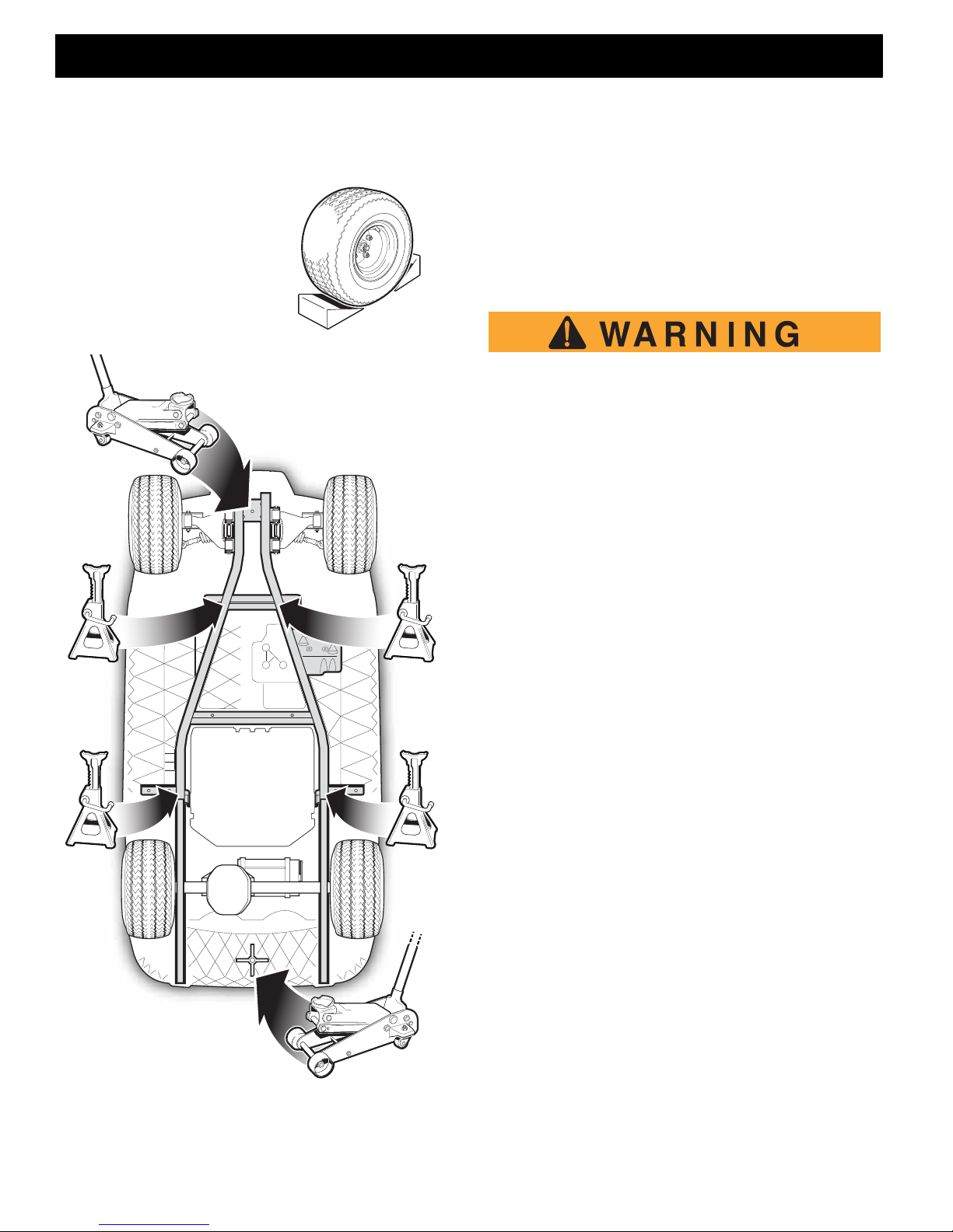
LIFTING THE VEHICLE
Tool List Qty.
Floor jack.......................... ... ... .... ... ... ...........................1
Jack stands.... ............................................. ... ... ... .... ... .4
Wheel Chocks..............................................................4
Some servicing operations may require the front
wheels, the rear wheels, or the entire vehicle be raised.
To reduce the possibility of severe injury or
death from a vehicle falling from a jack:
Be sure the vehicle is on a firm and level surface.
Never get under a vehicle while it is supported
by a jack.
Use jack stands and test the stability of the
vehicle on the stands.
Always place chocks in front and behind the
wheels not being raised.
Use extreme care since the vehicle is extremely unstable during the lifting process.
When lifting the vehicle, position the jacks and jack
stands at the areas indicated only.
To raise the entire vehicle, install the wheel chocks in
front and behind each front wheel. Center the jack under the bagwell and place a piece of wood, approximately 2" x 4" x 12", between the jack and the underside
of the bagwell. Raise the vehicle and position the jack
stands under the frame where the leaf spring mounting
bracket is welded to the frame.(Ref. Fig. 11)
Lower the jack and test the stability of the vehicle on the
two jack stands.
Place the jack under the center front of the car just behind the bumper. Raise the vehicle and position the jack
stands under the frame where the instrument panel support is attached to the frame.(Ref. Fig. 11)
Lower the jack and test the stability of the vehicle on all
four jack stands.
To raise only the front or rear of the vehicle, place the
wheel chocks in front and behind the wheels that are not
to be raised. The jack may be left under the center front
Owner’s Guide
Page 9
OPERATION AND SERVICE INFORMATION
Read all of this manual to become thoroughly familiar with this vehicle. Pay particular attention to all Notes, Cautions and Warnings.
of the frame while the front end of the vehicle is on the
jack stands.
B
Lower the vehicle by reversing the lifting sequence.
Fig. 10 Chock Wheels
T
Fig. 11 Lifting the Vehicle
WHEELS AND TIRES
TIRE REPAIR
Tool List Qty.
Lug wrench, 3/4"..........................................................1
Impact socket, 3/4" ......................................................1
Impact wrench..............................................................1
Torque wrench, ft. lbs...................................................1
A tire explosion can cause severe injury or
death. Never exceed the inflation pressure rating on the tire sidewall.
To reduce the possibility of tire explosion,
pressurize tire with small amount of air applied
intermittently to seat beads. Due to the low volume of the small tires, overinflation can occur
in seconds. Never exceed the tire manufacturer’s recommendation when seating a bead.
Protect face and eyes from escaping air when
removing a valve core.
To reduce the possibility of severe injury
caused by a broken socket when removing
wheels, use only sockets designed for impact
wrench use.
Use caution when inflating tires. Overinflation
could cause the tire to separate from the wheel
or cause the tire to explode, either of which
could cause severe injury.
DO NOT use low inflation tires on any E-Z-GO
vehicle. DO NOT use any tire which has a recommended inflation pressure less than the
inflation pressure recommended in the owner’s
guide.
Use caution when inflating tires. Due to the low volume
of the small tires, overinflation can occur in seconds.
Overinflation could cause the tire to separate from the
wheel or cause the tire to explode.
Tire inflation should be determined by the condition of the
terrain. See GENERAL SPECIFICATIONS section for
recommended tire inflation pressure. For outdoor applications with major use on grassy areas, the following
should be considered. On hard turf, it is desirable to have
a slightly higher inflation pressure. On very soft turf, a
lower pressure reduces the possibility of tires cutting into
the turf. For vehicles being used on paved or hard surfaces, tire inflation pressure should be in the higher allo wable range, but under no condition should inflation pres-
Page 10
Owner’s Guide
 Loading...