

E-Z-GO RXV GASOLINE, RXV FREEDOM, RXV SHUTTLE 2+2 Service & Repair Manual
RXV GASOLINE SERVICE & REPAIR
ISSUED FEBRUARY 2009 REVISED APRIL 2010
611104
SAFETY
NOTICE
DANGER
NOTICE
NOTICE
Ce système d'allumage par étincelle de véhicule respecte
toutes les exigences du Règlement sur le matériel brouilleur
du Canada.
For any questions on material contained in this manual, contact an authorized representative for clarification.
Read and understand all labels located on the vehicle. Always replace any damaged or missing labels.
On steep hills it is poss ible fo r vehicl es to coas t at greate r than no rmal spee ds enc ountered on a flat sur face. To prevent
loss of vehicle control and possible serious injury, speeds should be limited to no more than the maximum speed on level
ground. See GENERAL SPECIFICATIONS. Limit speed by applying the service brake.
Catastrophic damage to the drivetrain components due to excessive spee d may result from driving the vehicle above
specified sp eed . Da mag e c au se d by excessive s pee d may c au se a l os s of ve hic l e co n tr ol, i s co stl y, is considered abu se
and will not be covered under warranty.
For towing/transporting vehicle, refer to “TRANSPORTING VEHICLE”.
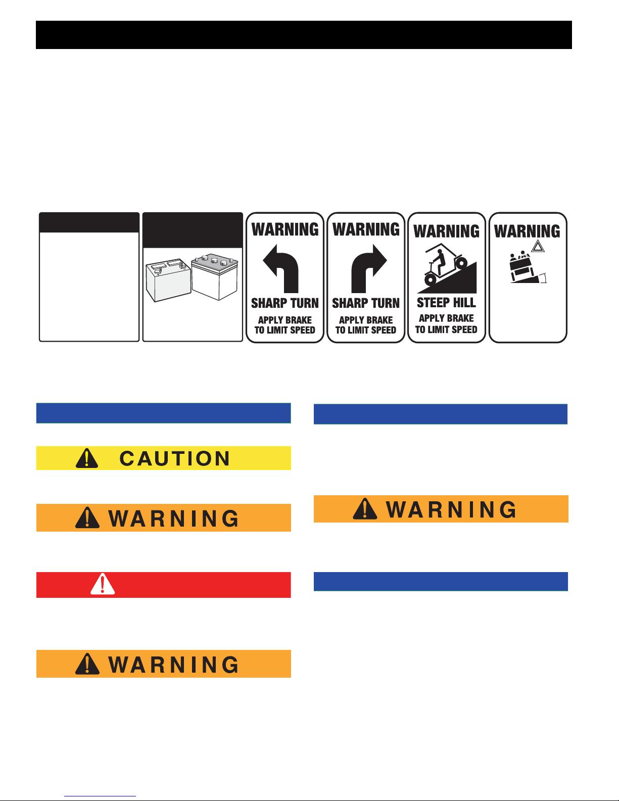
Signs similar to the ones illustrated should be used to warn of situations that could result in an unsafe condition.
BATTERY WARNING
Battery posts,
terminals and related
accessories contain
lead and lead compounds,
chemicals known
to cause cancer and
reproductive harm.
WASH HANDS
AFTER HANDLING!
Observe these NOTES, CAUTIONS and WARNINGS; be aware that se rvicing a vehicle r equires mechani cal skil l and a
regard for conditions that could be hazardous. Improper service or repair may damage the vehicle or render it unsafe.
BATTERIES
AND RELATED PARTS
CONTAIN LEAD
WASH HANDS
AFTER HANDLING!
WARNING: Battery posts, terminals and related
accessories contain lead and lead compounds,
chemicals known to cause cancer and reproductive harm.
!
<
14
˚
25
%
DO NOT
DRIVE ACROSS
SLOPES IN
EXCESS OF 14˚
NOTES, CAUTIONS, WARNINGS AND DANGERS
Address practices not related to personal injury.
Indicates a hazardous situation which, if not avoided,
could result in minor or moderate injury.
The exhaust emission s of th is vehic les’ eng ine compli es wit h
regulations set forth by the Environmental Protection Agency
(EPA) of the United States of America (USA) at time of man ufacture. Significant fines could result from modifications or tampering with the engine, fue l, igni ti on or ai r intake syst ems .
Indicates a hazardous situation which, if not
avoided, could re sult in de at h or s erio us in jur y.
Indicates a hazardous situation which, if not
avoided, will result in death or serious injury.
Engine exhaust from this product contains
chemicals known, in certain quantities, to
cause cancer, bir th def ect s, or o the r re prod uctive harm.
(NOTES, CAUTIONS, WARNINGS AND DANGERS CONTINUED ON INSIDE OF BACK COVER)
Battery posts, terminals and related accessories contain le ad and le ad com poun ds. Wa sh
hands after handling.
This spark ignition system mee ts all re qui remen ts of th e Cana dian Interfere nce-Causing Equipment Regulations.

SERVICE AND REPAIR MANUAL
GASOLINE POWERED
GOLF CARS & PERSONAL VEHICLES
RXV GOLF CAR
RXV FREEDOM™
RXV SHUTTLE 2 + 2
STARTING MID-MODEL YEAR 2009
(MANUFACTURED BEGINNING MARCH 16, 2009)
E-Z-GO Division of TEXTRON Inc. reserves the right to incorporate engineering and design changes to products in this Manual, without obligation to
include these changes on units leased/sold previously.
The information contained i n this Manual may be revised periodically by the E-Z-GO Division, and therefore is subject to change without notice.
The E-Z-GO Division DISCLAIMS LIABILITY FOR ERRORS IN THIS MANUAL, and the E-Z-GO Division SPECIFICALLY DISCLAIMS LIABILITY FOR
INCIDENTAL AND CONSEQUENTIAL DAMAGES resulting from the use of the information and materials in this Manual.
TO CONTACT US
NORTH AMERICA:
TECHNICAL ASSISTANCE & WARRANTY PHONE: 1-800-774-3946, FAX: 1-800-448-8124
SERVICE PARTS PHONE: 1-888-GET-EZGO (1-888-438-3946), FAX: 1-800-752-6175
INTERNATIONAL: PHONE: 001-706-798-4311, FAX: 001-706-771-4609
E-Z-GO DIVISION OF TEXTRON INC., 1451 MARVIN GRIFFIN ROAD, AUGUSTA, GEORGIA USA 30906-3852
Owner’s Manual and Service Guide
Page i

GENERAL INFORMATION
This vehicle has been designed and manufactured in the Unit ed S t a tes of Am erica (U SA) as
a ‘World Vehicle’. The Standards and Specifications listed in the following text originate in
the USA unless otherwise indicated.
The use of non Original Equipment Manufacturer (OEM) approved parts may void the
warranty.
Tampering with or adjusting the governor to permit vehicle to operate at above factory
specifications will void the vehicle warranty.
When servicing engines, all adjustment s and replace ment component s must be per original
vehicle specifications in order to maintain the United States of America Federal and State
emission certification applicable at the time of manufacture.
BATTERY PROLONGED STORAGE
All batteries will self disc harge over time. The rate of self discharge varies depending on the
ambient temperature and the age and condition of the batteries.
A fully charged battery will not freeze in winter temperatures unless the temperature falls
below -75° F (-60° C).
Page ii
Owner’s Manual and Service Guide

TABLE OF CONTENTS
TITLE PAGE
SAFETY .................................................................................................................INSIDE COVERS
GENERAL INFORMATION..............................................................................................................II
SAFETY INFORMATION ........................................................................... ..... ............................. ....V
TITLE SECTION
GENERAL INFORMATION & ROUTINE MAINTENANCE ..............................................................A
SAFETY ...........................................................................................................................................B
BODY...............................................................................................................................................C
WHEELS AND TIRES......................................................................................................................D
FRONT SUSPENSION AND STEERING........................................................................................E
SPEED CONTROL.................... ..... .... .......................................... ..... ...............................................F
ENGINE........................................................................................................................................... G
FUEL SYSTEM................................................................................................................................H
CONTINUOUSLY VARIABLE TRANSMISSION (CVT)....................................................................J
DIRECTION SELECTOR.................................................................................................................K
ELECTRICAL WIRING.....................................................................................................................L
BRAKES..........................................................................................................................................M
REAR SUSPENSION.......................................................................................................................N
REAR AXLE.....................................................................................................................................P
WEATHER PROTECTION..............................................................................................................Q
TROUBLESHOOTING.....................................................................................................................S
LIMITED WARRANTY......................................................................................................................T
GENERAL SPECIFICATIONS .........................................................................................................U
Repair and Service Manual
Page iii

Notes:
TABLE OF CONTENTS
Page iv
Repair and Service Manual

SAFETY INFORMATION
This manual has been designed to assist in maintaining the vehicle in accordance with procedures developed by the
manufacturer. Adherence to these procedures and troubleshooting tips will ensure the best possible service from the
product. To reduce the chance of personal injury or property damage, the following must be carefully observed:
Certain replacement parts can be used independently and/or in combination with other accessories to modify an E-ZGO-manufactured vehicle to permit the vehicle to operate at or in excess of 20mph. When an E-Z-GO-manufactured
vehicle is modified an any way by the Distributor, Dealer or customer to operate at or in excess of 20mph, UNDER
FEDERAL LAW the modified product will be a Low Speed Vehicle (LSV) subject to the strictures and requirements of
Federal Motor Vehicle Safety Standard 571.500. In these instances, pursuant to Federal law the Distributor or Dealer
MUST equip the product with headlights, rear lights, turn signals, seat belts, top, horn and all other modifications for
LSV’s mandated in FMVSS 571.500, and affix a Vehicle Identification Number to the product in accordance with the
requirements of FMVSS 571.565. Pursuant to FMVSS 571.500, and in accordance with the State laws applicable in the
places of sale and use of the product, the Distributor, Dealer or customer modifying the vehicle also will be the Final
Vehicle Manufacturer for the LSV, and required to title or register the vehicle as mandated by State law.
E-Z-GO will NOT approve Distributor, Dealer or customer modifications converting E-Z-GO products into LSV’s.
The Company, in addition, recommends that all E-Z-GO products sold as personal transportation vehicles BE OPERATED ONLY BY PERSONS WITH VALID DRIVERS LICENSES, AND IN ACCORDANCE WITH APPLICABLE STATE
REQUIREMENTS. This restriction is important to the SAFE USE AND OPERATION of the product. On behalf of E-ZGO, I am directing that E-Z-GO Branch personnel, Distributors and Dealers advise all customers to adhere to this
SAFETY RESTRICTION, in connection with the use of all products, new and used, the Distributor or Dealer has reason to believe may be operated in personal transportation applications.
Information on FMVSS 571.500 can be obtained at Title 49 of the Code of Federal Regulations, section 571.500, or
through the Internet at the website for the U.S. Department of Transportation - at Dockets and Regulation, then to Title
49 of the Code of Federal Regulations (Transportation).
GENERAL
Many vehicles are used for a variety of tasks beyond the original intended use of the vehicle; therefore, it is impossible
to anticipate and warn against every possible combination of circumstances that may occur. No warnings can take the
place of good common sense and prudent driving practices.
Good common sense and prudent driving practices do more to prevent accidents and injury than all of the warnings
and instructions combined. The manufacturer strongly suggests that all users and maintenance personnel read this
entire manual paying particular attention to the CAUTIONS and WARNINGS contained therein.
If you have any questions regarding this vehicle, contact your closest representative or write to the address on the back
cover of this publication, Attention: Product Service Department.
The manufacturer reserves the right to make design changes without obligation to make these changes on units previously sold and the information contained in this manual is subject to change without notice.
The manufacturer is not liable for errors in this manual or for incidental or consequential damages that result from the
use of the material in this manual.
This vehicle conforms to the current applicable standard(s) for safety and performance requirements.
These vehicles are designed and manufactured for off-road use. They do not conform to Federal Motor Vehicle Safety
Standards of the United States of America (USA) and are not equipped for operation on public streets. Some commu-
Repair and Service Manual
Page v

SAFETY INFORMATION
nities may permit these vehicles to be operated on their streets on a limited basis and in accordance with local ordinances.
Refer to GENERAL SPECIFICATIONS for vehicle seating capacity.
Never modify the vehicle in any way that will alter the weight distribution of the vehicle, decrease its stability
or increase the speed beyond the factory specification. Such modifications can cause serious personal injury
or death. Modifications that increase the speed and/or weight of the vehicle will extend the stopping distance and may
reduce the stability of the vehicle. Do not make any such modifications or changes. The manufacturer prohibits and
disclaims responsibility for any such modifications or any other alteration which would adversely affect the safety of the
vehicle.
Vehicles that are capable of higher speeds must limit their speed to no more than the speed of other vehicles when
used in a golf course environment. Additionally, speed should be further moderated by the environmental conditions,
terrain and common sense.
GENERAL OPERATION
Always:
• Use the vehicle in a responsible manner and maintain the vehicle in safe operating condition.
• Read and observe all warnings and operation instruction labels affixed to the vehicle.
• Follow all safety rules established in the area where the vehicle is being operated.
• Reduce speed to compensate for poor terrain or conditions.
• Apply service brake to control speed on steep grades.
• Maintain adequate distance between vehicles.
• Reduce speed in wet areas.
• Use extreme caution when approaching sharp or blind turns.
• Use extreme caution when driving over loose terrain.
• Use extreme caution in areas where pedestrians are present.
MAINTENANCE
Always:
• Maintain the vehicle in accordance with the manufacturer’s periodic service schedule.
• Ensure that repairs are performed by those that are trained and qualified to do so.
• Follow the manufacturer’s maintenance procedures for the vehicle. Be sure to disable the vehicle before performing
any maintenance. Disabling includes removing the key from the key switch and removal of a battery wire.
Page vi
Repair and Service Manual

SAFETY INFORMATION
• Insulate any tools used within the battery area in order to prevent sparks or battery explosion caused by shorting the
battery terminals or associated wiring. Remove the battery or cover exposed terminals with an insulating material.
• Use specified replacement parts. Never use replacement parts of lesser quality.
• Use recommended tools.
• Determine that tools and procedures not specifically recommended by the manufacturer will not compromise the
safety of personnel nor jeopardize the safe operation of the vehicle.
• Support the vehicle using wheel chocks and jack stands. Never get under a vehicle that is supported by a jack. Lift
the vehicle in accordance with the manufacturer’s instructions.
• Empty the fuel tank or plug fuel hoses to prevent fuel leakage.
• Maintain the vehicle in an area away from exposed flame or persons who are smoking.
• Be aware that a vehicle that is not performing as designed is a potential hazard and must not be operated.
• Test drive the vehicle after any repairs or maintenance. All tests must be conducted in a safe area that is free of both
vehicular and pedestrian traffic.
• Replace damaged or missing warning, caution or information labels.
• Keep complete records of the maintenance history of the vehicle.
The manufacturer cannot anticipate all situations, therefore people attempting to maintain or repair the vehicle must
have the skill and experience to recognize and protect themselves from potential situations that could result in severe
personal injury or death and damage to the vehicle. Use extreme caution and, if unsure as to the potential for injury,
refer the repair or maintenance to a qualified mechanic.
VENTILATION
Always store gasoline vehicles in a well ventilated area. Ventilation prevents gasoline fumes from accumulating.
Never fuel a vehicle in an area that is subject to flame or spark. Pay particular attention to natural gas or propane water
heaters and furnaces.
Never work around or operate a vehicle in an environment that does not ventilate exhaust gases from the area. Carbon
monoxide is a dangerous gas that can cause unconsciousness and is potentially lethal.
Repair and Service Manual
Page vii

Notes:
SAFETY INFORMATION
Page viii
Repair and Service Manual

GENERAL INFORMATION & ROUTINE MAINTENANCE
TABLE OF CONTENTS FOR SECTION ‘A’
SECTION TITLE PAGE NO.
SERIAL NUMBER LOCATION ................................................................................. A - 1
STARTING THE VEHICLE WITH A DISCHARGED BATTERY................................ A - 1
SERVICING THE VEHICLE ...................................................................................... A - 2
TOWING ................................................................................................................... A - 2
ROUTINE MAINTENANCE ....................................................................................... A - 3
POWERTRAIN MAINTENANCE ............................................................................... A - 3
BRAKES ................................................................................................................... A - 3
TIRES........................................................................................................................ A - 4
VEHICLE CLEANING AND CARE............................................................................ A - 4
SUN TOP AND WINDSHIELD .................................................................................. A - 4
HAULING .................................................................................................................. A - 4
WINTER OR PROLONGED STORAGE.................................................................... A - 5
HARDWARE ............................................................................................................. A - 5
PERIODIC SERVICE SCHEDULE ............................................................................ A - 6
LIST OF ILLUSTRATIONS
Fig. 1 Serial Number Steering Column Location ...................................................A - 1
Fig. 2 Serial Number Front Frame ........................................................................ A - 1
Fig. 3 Serial Number Rear Frame Rail.................................................................. A - 1
Fig. 4 Initial Service Chart ....................................................................................A - 2
Fig. 5 Neutral Lock ............................................................................................... A - 3
Fig. 6 Torque Specifications and Bolt Grades....................................................... A - 6
Fig. 7 Periodic Service Schedule ..........................................................................A - 6
Repair and Service Manual
Page A-i

GENERAL INFORMATION & ROUTINE MAINTENANCE
Read all of Section B and this section before attempting any procedure. Pay particular attention to all Notices, Cautions and Warnings
Notes:
Page A-ii
Repair and Service Manual
GENERAL INFORMATION & ROUTINE MAINTENANCE
Serial Number
Serial Number
Serial Number
Read all of Section B and this section before attempting any procedure. Pay particular attention to all Notices, Cautions and Warnings
Thank you for purchasing this vehicle. This repair manual contains information that will assist you in repairing
and maintaining this vehicle. Some illustrations may
show items that are optional for your vehicle. This guide
covers the operation of several vehicl es, the refore,
some illustrations may not repres ent you r vehic le. P hys ical differences in controls will be illustra ted.
This vehicle has been designed and ma nufactu red a s a
‘World Vehicle’. Some countries have individual requirements to comply with their specifications; therefor e,
some sections may not apply in your country.
Most of the service procedures in this guide c an be accomplished using common automotiv e hand to ols. Co ntact your service representative on servicing the vehicle
in accordance with the Periodic Servic e Schedule.
Service Parts Manuals as well as Repair and Se rv ice
Manuals are available from a local Dis tributor, an authorized Branch or the Service Pa rts Department. When ordering parts or requesting information for your vehicle ,
provide the vehicle model, serial number and manu facture date code.
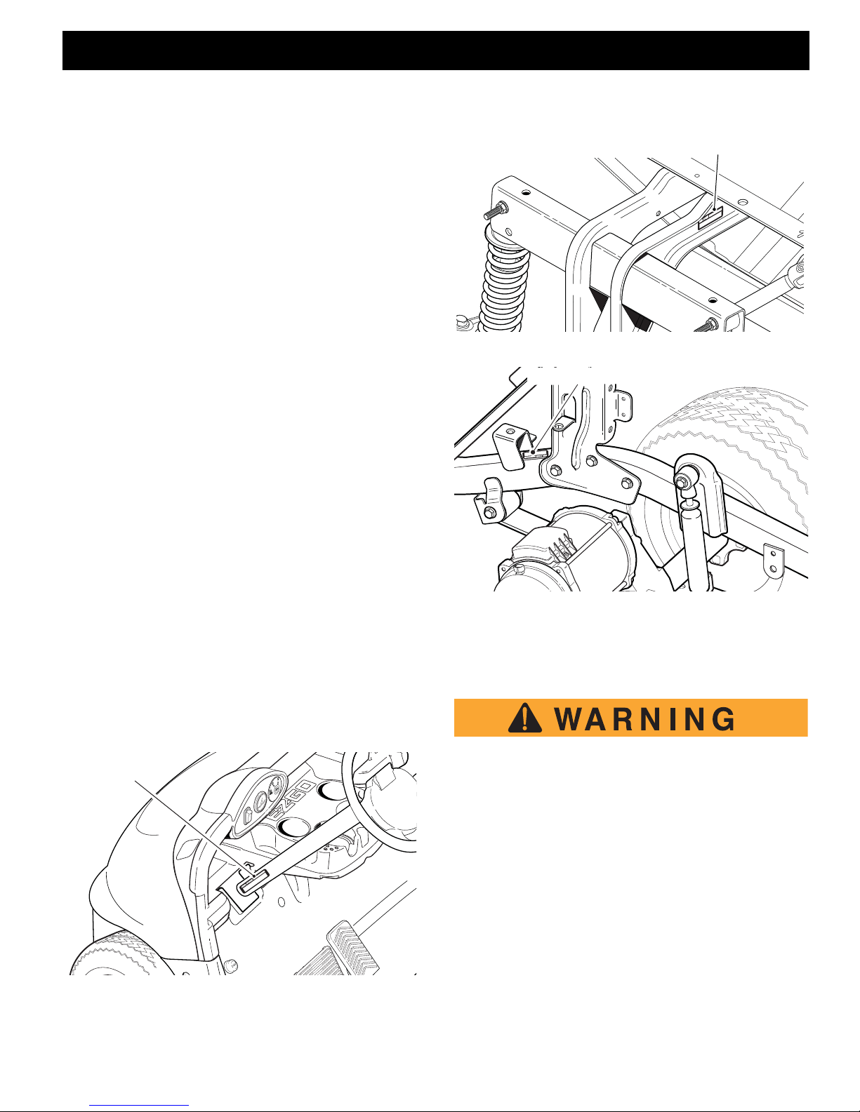
SERIAL NUMBER LOCATION
Three serial number and manufacture date co de pla tes
are on the vehicle. One is placed on the s teering co lumn, the second is located on the frame mem ber under
the front splash shield on the driver s ide, the thir d is l ocated on the passenger side frame rail at the rear of the
vehicle.
Design changes take place on an ongoing basi s. In order to obtain correct components for the vehicle, the
manufacture date code, serial number and v ehicle mo del must be provided when ordering servic e parts.
Fig. 2 Serial Number Plate Front Frame
Fig. 3 Serial Number Plate Rear Frame Rail
STARTING THE VEHICLE WITH
A DISCHARGED BATTERY
Fig. 1 Serial Number Plate Steering Column Location
Do not attempt to ‘jump start’ a vehicle using
another vehicle.
The vehicle is equipped with a starter/generator. When
starting the engine, the starter/generator functions as a
starter and with the engine running, it functions as a
generator.
With the short running times associated with this kind of
vehicle, the generator is more than adequate to main tain the battery charge level. The generator is not designed to charge a discharged battery.
Since the engine stops when the accelerator is released, jump starting should not be attempted.
If the vehicle is equipped with lights and/or accessories
that are used when the vehicle is not in motion, the
Repair and Service Manual
Page A-1
GENERAL INFORMATION & ROUTINE MAINTENANCE
Read all of Section B and thi s sec t io n be fore atte mp tin g an y procedure. Pay particular a tten tio n to all N oti ce s, Cautions and Warnings.
starter/generator may not be adequate to maintain battery charge. In this situation, the battery may require
B
charging with a 12V 10 amp max charger.
Observe all instructions provided by the manufacturer of
the charger.
SERVICING THE VEHICLE
To prevent severe injury or death, resulting
from improper se rv i ci ng te c h nique s , ob s erve
the following WARNINGS:
DO NOT attempt any type of servicing
operations before reading and understanding all notes, cautions and wa rning s in this
manual.
ANY servicing requiring ad justmen ts to be
made to the pow er tr ain whi l e th e mo tor is
running must be made with both drive
wheels raised.
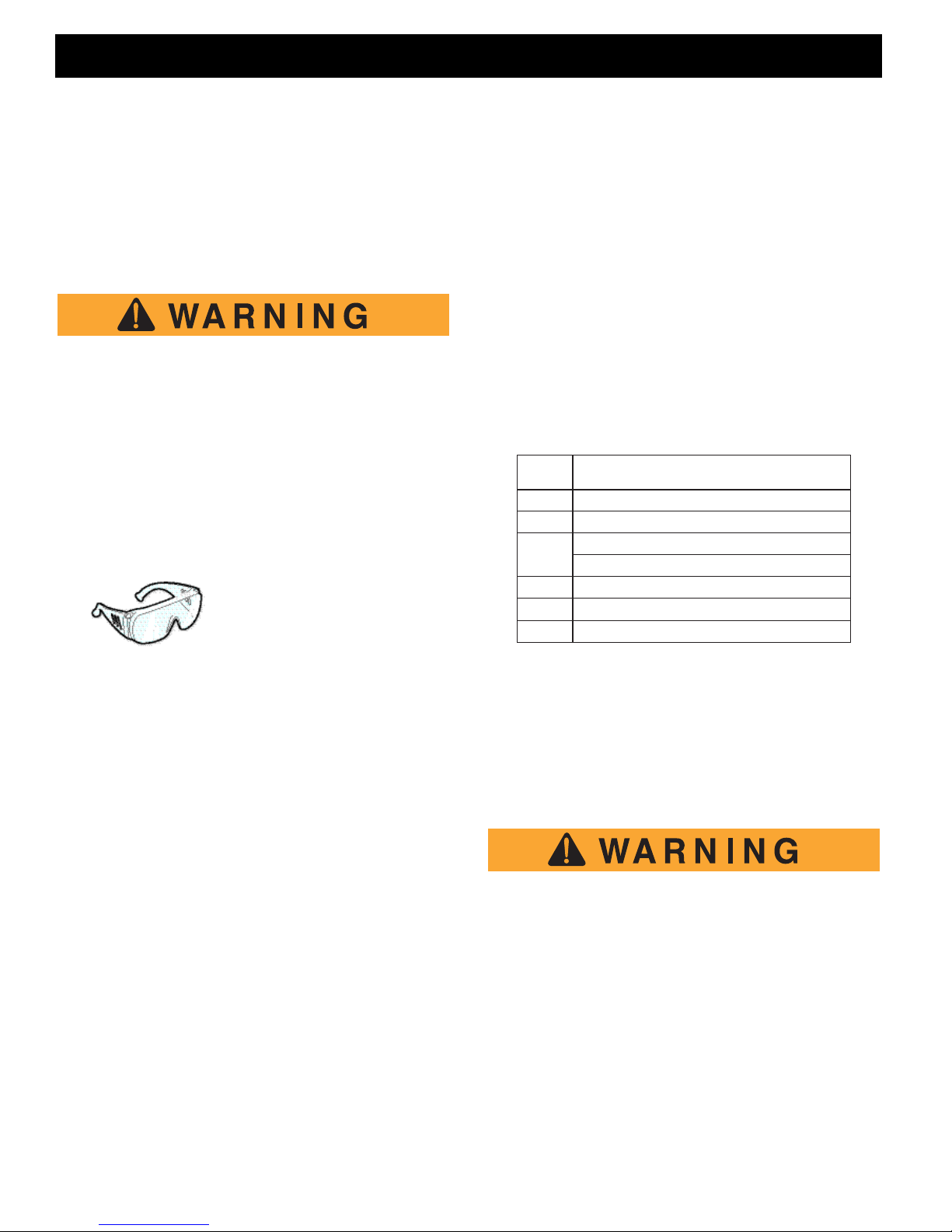
Wear eye protection when
working on the v ehicle. Use
extra care when working
around batteries, or using
solvents or compressed air.
To reduce the possibility of causing an
electrical arc, w hich could result in a battery
explosion, turn off all electrical loads from
the batteries before removing any heavy
gauge battery wires.
To prevent the possibility of motor disintegration, never operate vehicle at full throttle
for more than 4 - 5 seconds while vehicle is
in a “no load” condit ion .
It is in the best interest of both vehicle owner and servicing dealer, to carefully follow the procedures recommended in this manual. Adequate preventative maintenance, applied at regular intervals, is the best guarantee
for keeping the vehicle both dependabl e and economical.
In any product, components will eventually fail to perform properly as the result of normal use, age, wear or
abuse.
It is virtually impossible to anticipate all poss ible component failures or the manner in which each component
may fail.
A vehicle requiring repair ind ica tes the v ehic le is no
longer functioning as designed and s houl d be consi dered potentially hazardous. Use extreme c are whe n
working on a vehicle. When diagnos ing , remo vin g or replacing any components that are not operating properly,
consider the safety of yourself and those ar ound you,
should the component move unexp ectedly.
Some components are heavy, spring loaded, highly corrosive, explosive, may produce amperage or reac h high
temperatures. Gasoline, carbon monoxide , battery ac id
and hydrogen gas could result in serious bodily injury to
the technician/mechanic and bystanders, if not tr eated
with the utmost caution. Be careful not to pla ce han ds,
face, feet or body in a location that could expo se them
to injury should an unforeseen dangerous s ituation occur.
ITEM SERVICE OPERATION
Battery Charge battery
Seats Remove protective plastic covering
Brakes Check operation and adjust if necessary
Establish new vehicle braking distance
Tires Check air pressure (see SPECIFICATIONS)
Fuel Fill tank with correct fuel
Engine Check oil level
Fig. 4 Initial Service Chart
Always use the appropriate tools listed in th e tool l ist
and wear approved safety equipment.
Before a new vehicle is put into operation, it is recommended the items shown in the INITIAL SERVICE
CHART be performed.
TOWING
To reduce the possibility of severe injury o r
death:
Use extra caution when towing a vehicle.
DO NOT ride on the vehicle being towed.
DO NOT attempt to tow the vehicle with
ropes, chains or any device other than a
factory approved tow bar.
DO NOT tow the vehicle on highways.
DO NOT tow a single vehicle at speed s in
excess of 12 mph (19 kph).
Page A-2
Repair and Service Manual
GENERAL INFORMATION & ROUTINE MAINTENANCE
2
1
3
NOTICE
Read all of Section B and this section before attempting any procedure. Pay particular attention to all Notices, Cautions and Warnings
B
DO NOT tow more than three vehicles at a
time.
DO NOT exceed 5 mph (8 kph) while towing multiple vehicles.
DO NOT use the tow bar system on slopes
more than 10% grade.
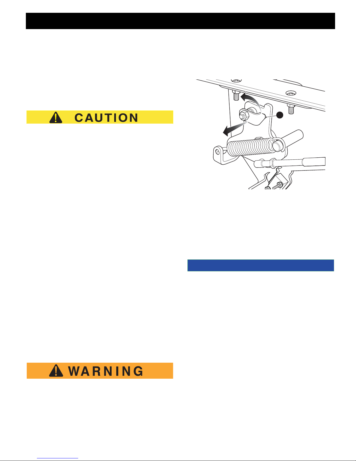
Place direction selector in neutral. The neutral lock
should be used to lock the direction selector in position. This will reduce the possibility of it moving into ‘F’
(for -ward) or ‘R’ (reverse) while being towed, causing
possible damage to the rear axle.
Use extra caution when towing vehicle. Do not tow a
single vehicle at speeds in excess of 12 mph (19 kph).
Do not tow more than three vehicles at a time. Do not
exceed 5 mph (8 kph) while towing multiple vehicles.The maximum slope that the tow bar system can
be used is 10% grade. Towing the vehicle at above
recommended speed may result in personal injury and
or damage to vehicle and other property.
Tow bars are not intended for road use.
To activate the direction selector, pull the neutral lock
pin handle out and rotate until the pointed portion of the
handle fits into the hole (3) in the direction selector cam
Fig. 5 Neutral Lock
ROUTINE MAINTENANCE
B
Tow bars are available from the Service Parts Department. Tow bars are designed to tow only one vehicle at
a maximum speed of 12 mph (19 kph) and up to three
vehicles at a maximum speed of 5 mph ( 8 kph). T he
maximum slope that the tow bar system can be used is
10% grade.Tow bars are not intended for highway use.
Before towing, place direction selector in neutr al a nd
engage neutral lock. Do not ride on vehicle being towed.
To operate neutral lock, first turn the key swi tch to
‘OFF’, place direction selecto r in ‘R’ an d rem ove s eat.
Pull out (1) and rotate (2) the neutral lock pin handle so
that the pointed portion of the handle is over the side of
the direct i on se l e ct or c am. M ove di r ec t i on se l e cto r le ve r
towards the area between ‘F’ and ‘R’. During that motion, the pin will snap into the hole in the direction selector mounting bracket, preventing any move ment of the
lever. When in this position, the direction selector remains locked in the neutra l pos ition .
Spring loaded mechanism. To prevent possibility of fingers becoming pinched in the direction selector mech an ism, hold dir ect ion
selector lever when releasing neutr al lock pin
handle.
This vehicle will give year s of sa tisf acto ry servi ce, providing it receives regular mainten ance. Re fer to the Periodic Service Schedule for appropriate service intervals
(Ref. Fig. 7).
.
Some maintenance items must be serviced more frequently on
vehicles used under sev ere dr ivi ng co ndi ti ons .
POWERTRAIN MAINTENANCE
Access the powertrain by raising or remov ing seat.
Some service procedures may requir e the v ehicle b e
lifted. Refer to LIFTING THE VEHICLE in section ‘B’ for
proper lifting procedure and safety information.
For maintenance procedures relating to the en gine,
speed control, fuel system, transmiss ion, a nd re ar axle
or suspension refer to the particular section. S ee the
TABLE OF CONTENTS for section location.
BRAKES
After the vehicle has been put into service, it is re commended that the brakes be checked by periodically conducting a brake performance test.
Repair and Service Manual
Page A-3

GENERAL INFORMATION & ROUTINE MAINTENANCE
NOTICE
NOTICE
Read all of Section B and thi s sec t io n be fore atte mp tin g an y procedure. Pay particular a tten tio n to all N oti ce s, Cautions and Warnings.
B
To prevent severe injury or death resulting
from operating a vehicle with improperly operating brake system, the braking system must
be properly mai ntai ne d. A ll dr iv ing br ak e te s ts
must be done in a safe location with regard for
the safety of all personnel
.
Over time, a subtle loss of perfo rmanc e may take pl ace .
Therefore, it is impor tant to es tabli sh th e stand ard w ith a new
vehicle.
For test method and brake service, refer to MECHANICAL BRAKES section.
TIRES
Tire condition should be inspected on a daily basis. Inflation pressures should be chec ked on a weekly basis
when the tires are cool. Be sure to reinstall valve dust
cap after checking or inflating tire. For additiona l info rmation, refer to WHEELS AND TIRES section.
The painted surfaces of the vehicle provide attracti ve
appearance and durable protection. Frequen t washi ng
with lukewarm or cold water and mild detergent is required to preserve the painted surface s.
Occasional cleaning and waxing with n on-a brasiv e
products designed for ‘clear coat’ automotive fi nis hes
will enhance the appearance and durab ility of the pa inted surfaces.
Corrosive materials used as fertilizers or for dust control
can collect on the underbody of the ve hicl e. These materials will cause corrosion of underbody parts unless
flushed occasionally with plain water. Thoroughly clean
any areas where mud or other debris can c olle ct. Se diment packed in closed areas should be loos ened to
ease its removal, taking care not to chip or o therwi se
damage paint.
If the engine does no t start or runs impro per ly after wa shi ng,
remove the spark plug wire (by pull in g th e spark pl ug boot ,
never the wire) and blow it dry. Reinstall the wire.
SUN TOP AND WINDSHIELD
VEHICLE CLEANING AND CARE
To reduce the possibility of severe injury or
vehicle damage, read and understand all
instructions s upp lie d b y th e manu f act ur er of
the pressure washer.
When pressure washing the exterior of the vehicle, do
not use pressure in excess of 700 psi. To reduce the
possibility of cosmetic damage, do not use any abrasive or reactive solvents to clean plastic parts.
It is important that proper techniques and cleaning materials be used. Using excessive water press ure may
cause severe injury to the operator or by stander, damage to the seals, plastics, seat material, body fini sh or
electrical system. Do not use pressure i n excess of 700
psi to wash the exterior of the vehicle.
Clean the windshield with lots of water, a mild soap and
a clean cloth.
Removal of oil, tar, asphalt, shoe polish, etc., requires
the use of a commercially available vi nyl /rub ber clea ner.
The sun top does not provide protection from
roll-over or falling objects.
The windshield does not provide protection
from tree limbs or flying objects.
The sun top and windshield provide some protection from t he e lem en ts ; h owe ver , they will
not keep the operator and passenger dry in a
downpour. This vehicle is not equipped with
seat belts and the sun top has not been
designed to provide roll-over protection. In
addition, the sun top does not protect against
falling objects nor does the windshield protect
against flying objects and tree limbs. Keep
arms and legs inside of the vehicle while it is
moving.
HAULING
To reduce the possibility of severe injury o r
death while transporting the vehicle:
Page A-4
Repair and Service Manual

GENERAL INFORMATION & ROUTINE MAINTENANCE
Read all of Section B and this section before attempting any procedure. Pay particular attention to all Notices, Cautions and Warnings
B
Secure the vehicle and contents.
Never ride on the v e hicl e b ein g tra nsp o rt -
ed.
Always remove the windshield before tr ans-
porting.
Maximum speed with sun top in stalled is 50
mph (80 kph).
If the vehicle is to be transported at highway
speeds, the su n to p mu st b e re mov ed and t h e
seat bottom secured. When transporting vehicle below highway speeds, check for tightness
of hardware and cracks in sun top at mounting
points. Always remove windshield when transporting. Always check that the vehicle and
contents are ad eq uat el y sec ur ed bef ore tr an sporting. The rated cap acit y of the tr ai ler or
truck must exceed the weight of the vehicle
(see GENERAL SPECIFICATIONS for vehicle
weight) and load plus 1000 lbs. (454 kg).
Secure the vehicle using ratchet tie downs.
HARDWARE
Periodically, the vehicle should be inspected for loose
fasteners. Fasteners should be tightened in accordance
with the Torque Specifications table (Ref. Fig. 6).
Use care when tightening fasteners and refer to the
Technician’s Repair and Service Manual for specific
torque values.
Generally, three classes of standard hardware and two
classes of metric hardware are use d in the vehi cle.
Grade 5 hardware can be identified by the three marks
on the hexagonal head and grade 8 hardware is ide ntified by 6 marks on the head. Metric hardware is marked
on the head with 8.8 or 10.9. Unmarked hardware is
Grade 2.
B
WINTER OR PROLONGED STORAGE
Keep hands, clothing and jewelry away from
moving parts. Use care not to contact hot
objects. Raise th e re ar of th e ve hi c le a nd s upport on jack stands before attempting to run
the engine.
Preparing the engine for winter or a prolonged storage
calls for a few simple steps to prevent build up of varnish and gum in the carburetor and corrosio n in the e ngine.
Place the direction selector in th e neutral pos iti on and
engage the neutral lock (Ref. Fig. 5). Add fuel stabilize r
to the tank in accordance with the manufacturer ’s recommendations. Close the fuel shut off valve located in
the fuel line between the tank and fuel filter. With proper
area of ventilation, start the engine and allow to run until
the engine stops due to lack of fuel. Remove the air filter
and spray a commercial fogging or cy lin der o il i nto the
carburetor while operating the starter for 2 - 3 seconds .
Reinstall the air filter and open the fuel shut off valve.
Repair and Service Manual
Page A-5

GENERAL INFORMATION & ROUTINE MAINTENANCE
ALL TORQUE FIGURES ARE IN FT. LBS. (Nm)
BOLT SIZE
Grade 2
1/4" 5/16" 3/8" 7/16" 1/2" 9/16" 5/8" 3/4" 7/8" 1"
Unless otherwise noted in text, tighten all hardware in accordance with this chart.
This chart specifies 'lubricated' torque figures. Fasteners that are plated or lubricated when
installed are considered 'wet' and require approximately 80% of the torque required for 'dry' fasteners.
4
(5)
8
(11)
15
(20)
24
(33)
35
(47)
55
(75)
75
(102)
130
(176)
125
(169)
190
(258)
Grade 5
Grade 8
6
(8)
13
(18)
23
(31)
35
(47)
55
(75)
80
(108)
110
(149)
200
(271)
320
(434)
480
(651)
6
(8)
18
(24)
35
(47)
55
(75)
80
(108)
110
(149)
170
(230)
280
(380)
460
(624)
680
(922)
BOLT SIZE
Class 5.8
(Grade 2)
M4 M5 M6 M8 M10 M12 M14
1
(2)
2
(3)
4
(6)
10
(14)
20
(27)
35
(47)
55
(76.4)
Class 8.8
(Grade 5)
2
(3)
4
(6)
7
(10)
18
(24)
35
(47)
61
(83)
97
(131)
Class 10.9
(Grade 8)
3
(4)
6
(8)
10
(14)
25
(34)
49
(66)
86
(117)
136
(184)
5.8
8.8
10.9
Read all of Section B and thi s sec t io n be fore atte mp tin g an y procedure. Pay particular a tten tio n to all N oti ce s, Cautions and Warnings.
.
B
Fig. 6 Torque Specifications and Bolt Grades
PERIODIC SERVICE SCHEDULE
* - CHECK C&A - CHECK & ADJUST CL - CLEAN R - REPLACE
REMARKS
20 rnds/20 hrs
100 miles/160 kms
before each use
DAILY
WEEKLY
Tires - pressure, condition of tires & rims ****** 13
Hardware - loose or missing
******
Reverse Warning I ndicator ******
Overall Vehicle Condition ******
Battery - state of charge, condition, loose terminals,
corrosion, hold down & hardware
Service Brake (Mechanical) - smooth operation
Brakes - aggressive stop test C&A C&A C&A C&A 15
Park Brake - operation, does it hold on a hill
Accelerator - smooth operation
Starter/Generator Belt - tension, wear, cracks *****
**CL CL CL CL 18
****** 15
Fig. 7 PERIODIC SERVICE SCHEDULE
**C&A C&A C&A C&A
******
MONTHLY
60 rnds/60 hrs
300 miles/500 kms
QUARTERLY
125 rnds/125 hrs
600miles/1000 kms
SEMI-ANNUAL
250 rnds/250 hrs
1200miles/2000 kms
ANNUAL
5 YEARS
PAGE
**Initial oil change after 8 hours of run time.
NOTE: Some maintenance items must be ser viced mo re frequen tly o n vehi cl es us ed unde r sever e driv ing c onditi ons.
Page A-6
Repair and Service Manual

GENERAL INFORMATION & ROUTINE MAINTENANCE
Read all of Section B and this section before attempting any procedure. Pay particular attention to all Notices, Cautions and Warnings
REMARKS
20 rnds/20 hrs
100 miles/160 kms
before each use
DAILY
WEEKLY
Wiring - loose connections, broken or missing insula-
tion
Carburetor Linkage - attachment C&A C&A C&A C&A
Carburetor CL
Direction Selector - attachment and mechanism C&A C&A C&A C&A
Cooling Fan - build up of deb ris in sid e blower housing C&A C&A C&A C&A C&A
Engine Oil ** - oil level C&A C&A C&A C&A C&A
Engine Oil **& Filter - drain and change R R
Engine - noise, vibration, acceleration, oil leaks C&A C&A C&A C&A
Valves - check cold - Ref: Repair & Service Manual C&A
Cylinder Head & Pistons - remove carbon CL
Choke Cable - smooth movement & adjustment C&A C&A C&A C&A
Cooling Fan - build-up of foreign matter inside hous-
ing & fins
Steering Assembly - excessive play, loose or missing
hardware
Tie Rods - exc es si ve pl ay, bent rod s, lo ose or mi ss ing
hardware
Rear Axle - fluid level, oil leakage, noise, loose or
missing hardware
Rear Axle - drain & replace fluid R
Rear Suspension - shock oil leakage, worn bushings,
loose or missing hardware
Front Suspension - strut oil leakage, excessive play in
hubs or kingpins, worn bushings, loose or missing
hardware
Front Wheel Alignment - unusual tire wear C&A C&A C&A
Fuel System - leaks at tank, cap, system lines for
cracks/deterioration, filters, pump
Fuel Filter R
Spark Plug R
Fig. 7 PERIODIC SERVICE SCHEDULE
MONTHLY
60 rnds/60 hrs
300 miles/500 kms
QUARTERLY
125 rnds/125 hrs
600miles/1000 kms
SEMI-ANNUAL
250 rnds/250 hrs
1200miles/2000 kms
ANNUAL
****
CL CL CL CL
****
****
****
***
****
***
5 YEARS
PAGE
B
B
**Initial oil change after 8 hours of run time.
NOTE: Some maintenance items must be ser viced mo re frequen tly o n vehi cl es us ed unde r sever e driv ing c onditi ons.
Repair and Service Manual
Page A-7

GENERAL INFORMATION & ROUTINE MAINTENANCE
Read all of Section B and thi s sec t io n be fore atte mp tin g an y procedure. Pay particular a tten tio n to all N oti ce s, Cautions and Warnings.
B
REMARKS
20 rnds/20 hrs
100 miles/160 kms
before each use
DAILY
WEEKLY
Throttle/Governor Linkage - operation & governed
speed
Air Filter Element - check & replace a s necessary **
Drive Belt - cracks, frayed, excessive wear **
Fig. 7 PERIODIC SERVICE SCHEDULE
**Initial oil change after 8 hours of run time.
NOTE: Some maintenance items must be ser viced mo re frequen tly o n vehi cl es us ed unde r sever e driv ing c onditi ons.
MONTHLY
60 rnds/60 hrs
300 miles/500 kms
QUARTERLY
125 rnds/125 hrs
600miles/1000 kms
SEMI-ANNUAL
250 rnds/250 hrs
***
1200miles/2000 kms
ANNUAL
5 YEARS
PAGE
Page A-8
Repair and Service Manual

GENERAL INFORMATION & ROUTINE MAINTENANCE
Read all of Section B and this section before attempting any procedure. Pay particular attention to all Notices, Cautions and Warnings
Notes:
Repair and Service Manual
Page A-9

GENERAL INFORMATION & ROUTINE MAINTENANCE
Read all of Section B and this section before attempting any procedure. Pay particular attention to all Notices, Cautions and Warnings
Notes:
Page A-10
Repair and Service Manual

SAFETY
TABLE OF CONTENTS FOR SECTION ‘B’
SECTION TITLE PAGE NO.
NOTES, CAUTIONS AND WARNINGS ..........................................................................1
IMPORTANT SAFETY WARNING ..................................................................................1
MODIFICATIONS TO VEHICLE......................................................................................1
GENERAL MAINTENANCE............................................................................................1
BEFORE SERVICING THE VEHICLE.............................................................................1
Battery Removal and Installation............................................................................2
LIFTING THE VEHICLE ..................................................................................................3
LIST OF ILLUSTRATIONS
Fig. 1 Battery Removal ...............................................................................................3
Fig. 2 Lifting the vehicle..............................................................................................3
Repair and Service Manual
Page B-i

SAFETY
Read all of Section B and this section before attempting any procedure. Pay particular attention to all Notices, Cautions and Warnings.
Notes:
Page B-ii
Repair and Service Manual

SAFETY
NOTICE
DANGER
Read all of Section B and this se ct ion before attempting any procedure. Pa y particular attention to all Not ic es, Cautions and Warnings.
B
NOTICES, CAUTIONS AND WARNINGS
Throughout this manual, the following NOTICES, CAUTIONS and WARNINGS are used. For the protection of
all personnel and the vehicle, be aware of and obser ve
the following:
Address practices not related to personal injury.
Indicates a hazardous situation which, if not avoided,
could result in minor or moderate injury.
Indicates a hazardous situation which, if not
avoided.
Indicates a hazardous situation which, if
not avoided, will result in death or serious
injury.
IMPORTANT SAFETY WARNING
In any product, components will eventu ally fail to perform
properly as the result of normal use, age, wear or abuse.
It is virtually impossible to anticipate all possible component failures or the manner in which each component
may fail.
Be aware that a vehicle requiring repair indi cate s that
the vehicle is no longer functioning as des igne d and
therefore should be considered potentially haz ar dous.
Use extreme care when working on any vehicle . When
diagnosing, removing or replacing any components that
are not operating correctly, take the time to consider the
safety ramifications if the component should move unexpectedly.
Some components are heavy, spring loaded, highly corrosive, explosive or may produce high amper age or
reach high temperatures. Gasoline, carbon monox ide,
battery acid and hydrogen gas could result i n ser ious
bodily injury to the technician/mechani c and b ystanders
if not treated with utmost caution. Be careful not to place
hands, face, feet or body in a location that could expose
them to injury should an unforeseen situation occ ur.
Always use the appropriate tools listed in the too l lis t
and wear approved safety equipment.
MODIFICATIONS TO VEHICLE
Do not modify the vehicle in any manner that will change
the weight distribution of the vehicle.
Changes to the weight distribution or the center of gravity may make the vehicle unstable or
prone to roll over which could result in injury or
death to the oper at or or p asse ng e r(s).
GENERAL MAINTENANCE
When any maintenance procedure or ins pecti on is performed, it is important that care be exercised to in su re
the safety of the technician/mechanic or bystanders and
to prevent damage to the vehicle.
Always read and understand the entire relevant manual
section (chapter) before attempting any i nspe ction or
service.
BEFORE SERVICING THE VEHICLE
Before attempting to inspect or se rvice a vehi cl e, be
sure to read and understand the following warnings:
To prevent personal injury or death, observe
the following:
Before working on the vehicle, remove all
jewelry (rings, watch, necklaces, etc.).
Be sure that no loose clothing or hair can
become caught in th e m ov in g p ar ts o f th e
powertrain.
Use care not to contact hot objects.
Before attempting to operate or adjust the
powertrain, the re ar of the v ehic l e mus t be
raised and supp or ted on jack st ands .
Wear OSHA approved clothing and eye
protection when working on anything that
could expose the body or eyes to potential
injury. In particular, use care when working
with or around batteries, compre ssed air or
solvents.
B
Repair and Service Manual
Page B-1

SAFETY
Read all of Section B and thi s s ect io n be fore atte mp tin g any procedure. Pay particu lar a tten tio n to all Notices, Cautions and Warnings.
Always turn the key switch to ‘OFF’ and
B
remove the key before disconnecting a live
circuit.
When connecting battery cables, pay particular attention to the polarity of the bat tery
terminals. Never confuse the positive and
negative c ables.
Set the parking ‘PARK’ brake before performing any work on th e ve hicle.
If repairs are to be made that will require
welding or cutting, the battery an d fu el tan k
must be removed and the fuel system
drained.
To prevent expl osio n th at cou ld resu lt in
severe personal injury or death, keep all smoking materials, op en fla me or spa rks aw ay f rom
gasoline and b att e rie s.
Never operate the starter with the spark
plugs removed unless the ignition system
has been disab led an d t he e ng ine / exh au st
are cold. Fuel expelled from the cylinders
could be ignited by the ignition system or
the hot exhaust system.
Never work on an en gi ne th a t is h ot.
Never test the ignition system without either
connecting the spark p lug lead to a teste r or
spare grounded spark plug.
If the spark function is to be obse rved at the
spark plug, be sure to install a spare spark
plug into the open cylinder before operating
the starter.
Never test the fun ction of a fuel p ump in t he
vicinity of a hot engine or other source of
flame or combu sti on .
Never confus e the ho ses t o and f rom th e
fuel pump. Verify that the carburetor and
pulse lines are c or re ctl y installed before
starting the engine (see FUEL SYSTEM
section).
Wrap wrenches with vinyl
tape to prevent the possibility of a dropped wrench
from ‘shorting out’ a battery, which could result in
an explosion and severe personal injury or
death.
Aerosol contai ne rs of b at ter y te rmina l pro tectant must be used with extreme care.
Insulate metal container to prevent can
from contacting battery terminals which
could result in an ex pl os ion .
To prevent illness or death, observe the following:
Never work around or operate a vehicle in
an environment that does not ventilate
exhaust gases from the area.
Exhaust gas (carbon monoxide) is deadly.
Carbon monoxide i s an odorle ss gas that is
formed as a natural part of the incomplete
combustion of hydrocarbon fuels. Carbon
monoxide is a dang e rou s ga s th a t ca n
cause unconsciousness and is potentially
lethal.
The following are symptoms of carbon
monoxide inhalation:
•Dizziness
•Vomiting
•Intense headache
•Muscular twitching
•Weakness and sleepiness
•Throbbing in temples
If experiencing any of these symptoms, get
fresh air immediately.
BATTERY REMOVAL AND INSTALLATION
Tool List Qty.
Insulated Wrench, 1/2"..................................... ....... .....1
Socket, 1/2"..................................................................1
Extension, 12"..............................................................1
Ratchet ........................................................................1
Battery Carrier ....................... ....... ...... ....... ...... ....... .....1
Page B-2
Repair and Service Manual
SAFETY
NOTICE
Read all of Section B and this se ct ion before attempting any procedure. Pa y particular attention to all Not ic es, Cautions and Warnings.
in front and behi nd the wh e els n ot be in g
raised. Use extr em e car e sin c e the veh icl e is
In the following text, there are references to removing/installing
bolts etc. Additional hardware (nuts, washers, etc.) that is
removed must always be installed in its original position unless
otherwise specified . N on-s peci fi ed torqu es are as sh ow n in
table contained in Section ‘A’.
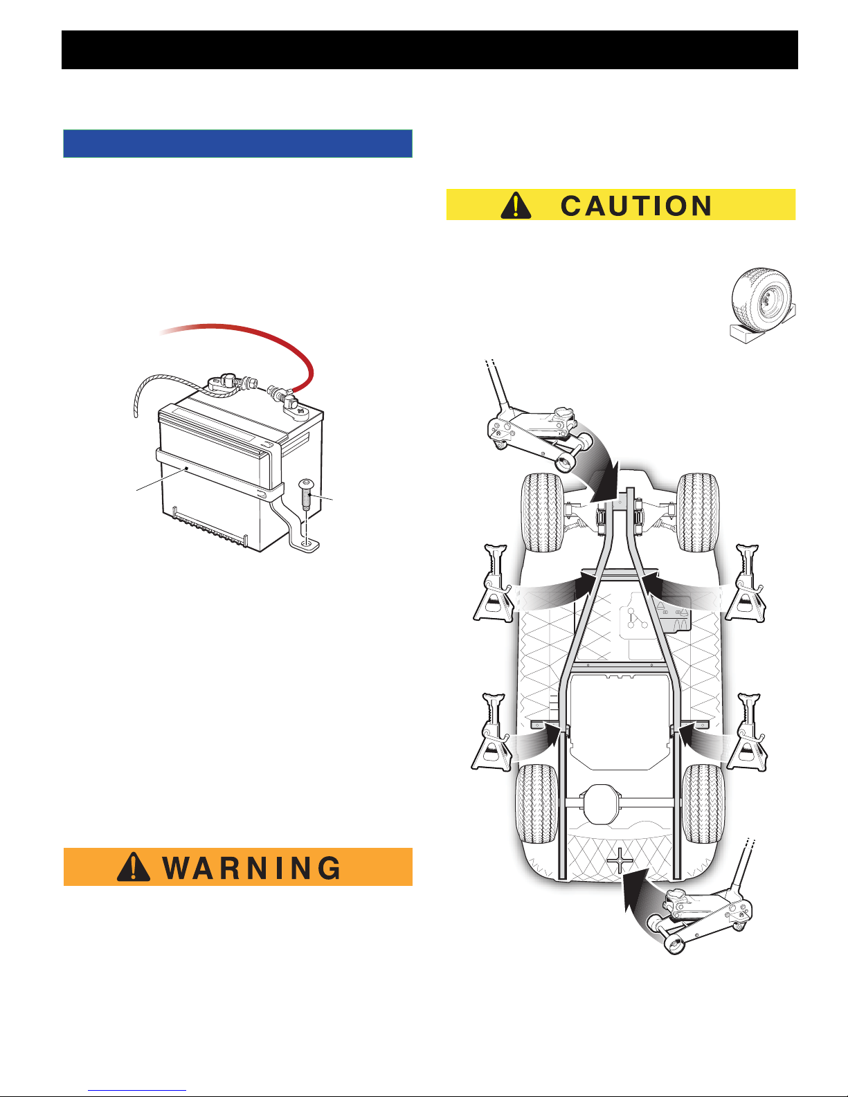
At the battery, remove hardware from the negative (-)
cable before removing the positive (+) cable. Remov e
the bolt from the battery hold down and remove the battery (Ref. Fig. 1).
BATTERY -
BATTERY +
extremely uns tab le durin g t he lif ti ng pr oc es s.
When lifting the vehicle, position jacks and jack stands
only on the areas indicated.
To raise the entire vehicle, install chocks in
front and behind each front wheel. Center
the jack under the rear frame crossmember.
Raise the vehicle and locate a jack stand
under the outer ends of the rear axle.
B
B
BATTERY
TIE DOWN
Connect the positive (+) battery cable first. Connect
negative (-) battery cable last.
Be sure to remove all corrosion from terminals and hardware. After installing battery, coat terminals with c ommercially available terminal protectant.
BATTERY
Fig. 1 Battery Removal
TIE DOWN
SCREW
LIFTING THE VEHICLE
Tool List Qty.
Floor Jack.................................................................... 1
Jack Stands................................................................. 4
Chocks ........................................................................ 4
Some servicing operations may require the front, rear or
the entire vehicle to be raised.
To prevent possible injury or death resulting
from a vehicle falling from a jack, be sure the
vehicle is on a firm and level surface. Never
get under a vehicl e wh ile i t is su pp or ted by a
jack. Use jack stands and test the stability of
the vehicle on the stands. Always place c hocks
Repair and Service Manual
Fig. 2 Lifting the Vehicle
Page B-3

SAFETY
Read all of Section B and thi s s ect io n be fore atte mp tin g any procedure. Pay particu lar a tten tio n to all Notices, Cautions and Warnings.
Lower the jack and test the stability of the vehicle on the
two jack stands.
B
Place the jack at the center of the front axle. Raise the
vehicle and position jack stands under the fra me cros smember as indicated.
Lower the jack and test the stability of the vehicle on all
four jack stands.
If only the front or rear of the vehicle is to be raised,
place the chocks in front and behind each wheel not
being raised in order to stabilize the vehicle.
Lower the vehicle by reversing the lifting sequenc e.
Page B-4
Repair and Service Manual

SAFETY
Read all of Section B an d thi s s ec tio n be fore atte mpting any procedure. Pay par tic ula r atte nti on t o al l N oti ce s, Cautions and Warnings.
NOTES:
Repair and Service Manual
Page B-5

SAFETY
Read all of Section B and this se ction before attempting any proc edu re. Pay particular attention to a ll Notices, Cautions and Warnings.
Notes:
Page B-6
Repair and Service Manual
 Loading...