

Ezgo RXV ELECTRIC, RXV FREEDOM, RXV FLEET, RXV SHUTTLE 2+2 Service & Repair Manual
RXV ELECTRIC SERVICE & REPAIR
ISSUED JANUARY 2008 REVISED APRIL 2009
605975
WASH HANDS
AFTER HANDLING!
Battery posts,
terminals and related
accessories contain
lead and lead compounds,
chemicals known
to cause cancer and
reproductive harm.
BATTERY WARNING
WASH HANDS
AFTER HANDLING!
WARNING: Battery posts, terminals and related
accessories contain lead and lead compounds,
chemicals known to cause cancer and reproductive harm.
BATTERIES
CONTAIN LEAD
AND RELATED PARTS
!
<
14
˚
25
%
DO NOT
DRIVE ACROSS
SLOPES IN
EXCESS OF 14˚
SAFETY
For any questions on material contained in this manual, contact an authorized representative for clarification.
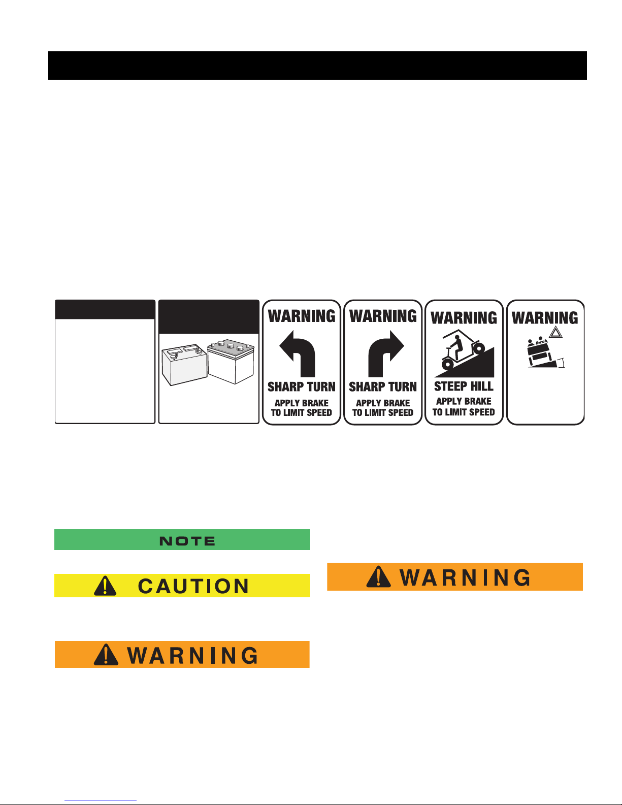
Read and understand all labels located on the vehicle. Always replace any damaged or missing labels.
On steep hills it is possib le for vehi cles to coa st at greater than nor mal speeds encountered on a flat s urface. To pre-
vent loss of vehicle co ntrol and pos sib le seriou s inju ry, speeds should be limited to no more than the max imum sp eed
on level ground. See GENERAL SPECIFICATIONS. Limit speed by applying the service brake.
Catastrophic damag e to the d rivetra in comp onents due to excessi ve speed may re sult fr om drivin g the vehi cle above
specified spe ed. Damage caused by excess ive speed may cause a los s of vehicle control, is co stly, is considered
abuse and will not be covered under warranty.
Use extra caution wh en t owi ng t he veh icle (s) . Do no t to w a si ngl e v eh icle at sp eed s in ex ce ss of 12 mph (19 kph). Do
not tow more than three v ehicles at a time. Do not exceed 5 mph (8 kph) whil e towing multiple vehic les. Towing the
vehicle at above the r ecommended s peed may r esult in per sonal injur y and/or damag e to the vehi cle and other p roperty. Vehicles equipped with the AC Drive motor must be towed with the Run-Tow switch, located under the passenger
seat, in the ‘T ow’ position.
If the vehicle is to be used in a commercial environment, signs similar to the ones illustrated should be used to warn of
situations that could resul t in an unsafe condition
Be sure that this manual remains as part of the permanent service record should the vehicle be resold.
NOTES, CAUTIONS AND WARNINGS
Throughout this guide NOTE, CAUTION and WARNING
will be used.
A NOTE indicates a condition that should be observed.
A CAUTION indicates a condition that may result in
damage to the vehicle.
A WARNING indicates a hazardous condi-
tion that could result in severe injury or
death.
(NOTES, CAUTIONS AND WARNINGS CONTINUED ON INSIDE OF BACK COVER)
Please observe these NOTES, CAUTIONS an d WARNINGS; be aware that servicing a vehicle requires
mechanical ski ll an d a re ga rd f or con d iti on s t h at co ul d be
hazardous. Improper service or repair may damag e the
vehicle or render it unsafe.
Battery posts, terminals and related
accessories contain lead and lead compounds. Wash hands after handling.

SERVICE AND REPAIR MANUAL
ELECTRIC POWERED
GOLF CARS & PERSONAL VEHICLES
RXV FLEET GOLF CAR
RXV FREEDOM GOLF CAR
RXV SHUTTLE 2+2
E-Z-GO Division of TEXTRON, Inc. rese rves the right to make design changes without obligation to make these changes on units previou sly sold and the information contained in this manual is subject to change without notice.
E-Z-GO Division of TEXTRON, Inc. is not liabl e for er rors in t his man ual or f or incid ent al or cons eque ntial da mages tha t resu lt from the use of the material in this
manual.
TO CONTACT US
NORTH AMERICA:
TECHNICAL ASSISTANCE & WARRANTY PHONE: 1-800-774-3946, FAX: 1-800-448-8124
SERVICE PARTS PHONE: 1-888-GET-EZGO (1-888-438-3946), FAX: 1-800-752-6175
INTERNATIONAL:
SALES PHONE: 001-706-798-4311, FAX: 001-706-771-4609
E-Z-GO DIVISION OF TEXTRON, INC., 1451 MARVIN GRIFFIN ROAD, AUGUSTA, GEORGIA USA 30906-3852
STARTING MODEL YEAR 2008
Repair and Service Manual
Page i

GENERAL INFORMATION
This vehicle has been designed and manufactured in the United States of America (USA ) as
a ‘World Vehicle’. The Standards and Specifications listed in the following text originate in
the USA unless otherwise indicated.
The use of non Original Equipment Manufacturer (OE M) approved parts may void the
warranty.
Overfilling batteries may void the warranty.
BATTERY PROLONGED STORAGE
All batteries will self discharge ove r time. The ra te of self disc harge vari es depending on the
ambient temperature and the age and condition of the batteries.
A fully charged battery will not freeze in winter temperatures unless the temperature falls
below -75° F (-60° C).
For winter storage, the batteries must be clean, fully charged and disconnected from any
source of electrical drain. The battery charger and the controller are both sources of
electrical drain. Unplug the battery charger DC plug from the vehicle receptacle.
On PDS vehicles, disconnect the controller from the battery set by selecting the ‘TOW/
MAINTENANCE’ position on the RUN-TOW/MAINTENANCE SWITCH located under the
passenger seat.
As with all electric vehicle s, the batte ries must be ch ecked and rechar ged as required or at a
minimum of 30 day intervals.
Page ii
Repair and Service Manual

TABLE OF CONTENTS
TITLE PAGE
SAFETY .......................................................................................................................Inside Covers
MODELS........................................................................................................................................... i
GENERAL INFORMATION...............................................................................................................ii
SAFETY INFORMATION ........................................................................... ...................................... v
TITLE SECTION
GENERAL INFORMATION & ROUTINE MAINTENANCE ..............................................................A
SAFETY ...........................................................................................................................................B
BODY...............................................................................................................................................C
WHEELS AND TIRES......................................................................................................................D
ELECTRONIC SPEED CONTROL (AC MOTOR)............................................................................E
FRONT SUSPENSION....................................................................................................................F
MOTOR & MOTOR BRAKE............................................................................................................ G
BATTERIES & CHARGING..............................................................................................................H
BATTERY CHARGER........................ .......................................... .......................................... ...........I
BRAKES........................................................................................................................................... J
ELECTRICAL COMPONENTS & WIRING.......................................................................................K
REAR SUSPENSION....................................................................................................................... L
REAR AXLE....................................................................................................................................M
WEATHER PROTECTION...............................................................................................................N
TROUBLESHOOTING.................................................................................................................... O
LIGHTNING PROTECTION & GROUNDING ..................................................................................P
SPECIFICATIONS........................................................................................................................... Q
Repair and Service Manual
Page iii

Notes:
TABLE OF CONTENTS
Page iv
Repair and Service Manual

SAFETY INFORMATION
Read all of manual to become thoroughly familiar with this vehicle. Pay particular attention to all Notes, Cautions and Warnings
This manual has been designed to ass ist the owner -operato r in maintaining th e vehi cl e in ac cordanc e with p rocedures developed by the manufacturer. Adherence to these procedures and troubles hooting tips will ensure the bes t
possible service from the product. To reduce the chance of personal injury and/or property damage, the following
instructions must be carefully observed:
GENERAL
Many vehicles are used for a variety of tasks beyond the original intended use of the vehicle; therefore it is impossible
to anticipate and warn against every possible combin ation of c ircum stances that m ay oc cu r. No warnings can take
the place of good common sense and prudent dr iv ing p ractic es.
Good common sense and prudent driv ing pr actice s do more to prevent accidents and injury than all of the war ning s
and instructions combined. The manufactur er str ongl y su ggests that the owner-oper ator rea d this entire manu al paying particular attention to the CAUTIONS and WARNINGS contained therein. It is further recommended that employees and other operators be encouraged to do the same.
If you have any questions, contact your clo sest repr esentative or write to the addr ess on the back cover of this publication, Attention: Custome Care Department.
E-Z-GO Division of Textron reserves the right to make design c hange s witho ut obli gation to make these c hange s on
units previously sold and the information contained in this manual is subj ect to c hange wi thout notice.
E-Z-GO Division of T extron is not liable for errors in this manual or for incidental or consequential damages that result
from the use of the material in this manual.
This vehicle conforms to the current appl icable s tandard for safety and per formanc e re quirements.
These vehicles are designed and manufactur ed for off-road use. The y do not conform to Federal Motor Vehicle
Safety Standards and are not equipped for operation on public streets. Some communities may permit these vehicles
to be operated on their streets on a limited basi s and in acc or danc e with lo cal ordinanc es.
With electric powered vehicles, be sure that all e lectric al acce ss ories ar e gr ounded directl y to the b attery (-) post.
Never use the chassis or body as a ground connection.
Refer to GENERAL SPECIFICATIONS for vehicle seating capacity.
Never modify the vehicle in any way that will alter the weight distribution of the vehicle, decrease its stability
or increase the speed beyond the factory specification. Such modif ications can cause se rious personal
injury or death. Modifications that increase the speed and/or weight o f the veh icl e will exten d the sto pping d istance
and may reduce the stability of the vehicle. Do not make any s uch modifi cati ons o r changes . The manufa ctur er prohibits and disclaims responsibility for any such modificati ons or any other alteration which would adversely affect the
safety of the vehicle.
Vehicles that are capable of higher speeds must limit their speed to no more than the speed of other vehi cle s when
used in a golf course environment. Additionally, speed should be further moderated by the environmental conditions,
terrain and common sense.
Always use the vehicle in a responsible manner and maintain the vehicle in sa fe operating c ondi tion.
Always read and observe all warnings and ope ration ins truc tion label s affixed to the vehic le.
Always follow all safety rules es tablished in the ar ea wher e the vehic le i s being oper ated.
GENERAL OPERATION
Repair and Service Manual
Page v

SAFETY INFORMATION
Read all of Section B and this section before attempting any procedure. Pay particular attention to all Notes, Cautions and Warnings.
Always reduce speed to compensate for poor ter rain or condi tions.
B
Always apply service brake to co ntrol spee d on ste ep gr ades .
Always maintain adequate distance between vehicles.
Always reduce speed in wet areas.
Always use extreme caution when appr oach ing shar p or blind tu rns.
Always use extreme caution when driving over loose terrain.
Always use extreme caution in are as where ped estr ians are pre sent.
MAINTENANCE
Always maintain your vehicle in acc ordance wi th the man ufactur er’s periodic service schedul e.
Always ensure that mechanics per form ing repairs a re tr aine d and qua lifi ed to do so .
Always follow the manufacturer’s directions if you do any maintenance on yo ur vehic le. Be sure to disa ble the vehic le
before performing any maintenance. Disabling includes removing the key from the key switch and removal of a battery
wire.
Always insulate any tools used within the battery area in order to prevent sparks or battery explosi on caus ed by s horting the battery terminals or associated wiring. Remov e the ba tteri es or co ver expo sed ter mi nals with an insul ating
material.
Always check the polarity of each batter y termina l and be sur e to rewir e the batter ies cor rectl y.
Always use specified replacem ent parts. Never use re placement parts of less er q ualit y.
Always use recommended tools.
Always determine that tools and proce dures not s pecif ically recomm ended by the ma nufactu rer will not c ompr omise
the safety of personnel nor jeopardize the safe operation of the veh icl e.
Always support the vehicle using wheel c hocks and sa fety s tands. Never get under a v ehic le that is s upported by a
jack. Lift the vehicle in accordance with the manufactur er’s instructions.
Never attempt to maintain a vehicle in an area where exposed flame is present or persons are smok ing.
Always be aware that a vehicle that is not performing as d esi gned is a poten tial ha zar d and m ust not b e operated.
The manufacturer cannot anticipate all situations, therefore peopl e attempti ng to mai ntain or repair the vehic le must
have the skill and experience to recognize and protect themselves from poten tial situation s that coul d result in severe
personal injury or death and damage to the veh icl e. Use extr eme ca ution an d, if uns ure as to th e potenti al for inju ry,
refer the repair or maintenance to a qualified mechanic.
Always test drive the vehicle after any repairs or maintenance. All tests must be conducted in a safe area that is free of
both vehicular and pedestrian traffic.
Always replace damaged or missing war nin g, cauti on or informati on labe ls.
Always keep complete records of the mai ntenance his tor y of the v ehicle.
Page vi
Repair and Service Manual

SAFETY INFORMATION
Read all of Section B and this section before attempting any procedure. Pay particular attention to all Notes, Cautions and Warnings.
VENTILATION
Hydrogen gas is generated in the charging cyc le of batteri es an d is e xplosi ve in conc entrations as l ow as 4% .
Because hydrogen gas is lighter than air, it will collect in the ceiling of buildi ngs neces sitating proper ve ntilati on. Fiv e
air exchanges per hour is conside red the mini mum r equi rement.
Never charge a vehicle in an area that is subject to fl ame or spark. Pay particula r atten tion to na tural gas o r propane
gas water heaters and furnaces.
Always use a dedicated circuit for each battery charger. Do not permit other appliances to be plugged into the receptacle when the charger is in operation.
Chargers must be installed and operated in accordance with c harger manufac turers rec omme ndation s or appli cable
electrical code (whichever is m ore res trictiv e).
B
B
Repair and Service Manual
Page vii

SAFETY INFORMATION
Read all of Section B and this section before attempting any procedure. Pay particular attention to all Notes, Cautions and Warnings.
Notes:
Page viii
Repair and Service Manual

GENERAL INFORMATION & ROUTINE MAINTENANCE
TABLE OF CONTENTS FO R SECT ION ‘A’
SECTION TITLE PAGE NO.
SERIAL NUMBER LOCATION..................................................................................A - 1
TOWING ...................................................................................................................A - 2
SERVICING VEHICLE..............................................................................................A - 2
ROUTINE MAINTENANCE ...................................................................................... A - 3
REAR AXLE..............................................................................................................A - 3
TIRES........................................................................................................................A - 3
VEHICLE CLEANING AND CARE.............................................................................A - 3
SUN TOP AND WINDSHIELD ................................................................................... A - 3
HAULING..................................................................................................................A - 3
HARDWARE .............................................................................................................A - 4
CAPACITIES AND REPLACEMENT PARTS ............................................................A - 4
PERIODIC SERVICE SCHEDULE ............................................................................A - 5
LIST OF ILLUSTRATIONS
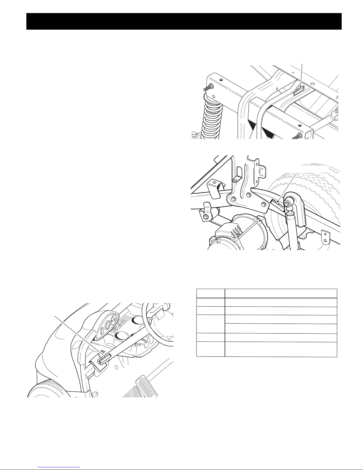
Fig. 1 Serial Number Location on St eeri ng C olumn ......... ... ... ... ...... ... .... ... ... ... ...... . A - 1
Fig. 2 Serial Number on Front Fr ame ........ ... ... ... ... .... ...... ... ... ... ... ...... .... ... ... ... ...... . A - 1
Fig. 3 Serial Number on Rear Fr ame ......... ... ... ... ....... ... ... ... ... ...... ... ... .... ... ...... ... ... . A - 1
Fig. 4 Initial Service Char t ................ ... ... ... ...... ... ... .... ... ...... ... ... ... ... ....... ... ... ... ... .... A - 1
Fig. 5 Capacities ........ ...... ... ... ... ... ....... ... ... ... ... ...... .... ... ... ... ...... ... ... ... .... ...... ... ... ... . A - 4
Fig. 6 Replacement Parts . ... ...... ... .... ... ... ...... ... ... ... .... ...... ... ... ... ... ...... .... ... ... ... ...... . A - 4
Fig. 7 Torque Specifications a nd Bo lt Gr ades..................... ... ... ... ... ....... ... ... ... ... .... A - 4
Fig. 8 Periodic Service Sche dule............... ... ... ... ... .... ...... ... ... ... ... ...... .... ... ... ... ...... . A - 5
Repair and Service Manual
Page A-i

GENERAL INFORMATION & ROUTINE MAINTENANCE
Read all of Section B and this section before attempting any procedure. Pay particular attention to all Notes, Cautions and Warnings.
Notes:
Page A-ii
Repair and Service Manual
GENERAL INFORMATION & ROUTINE MAINTENANCE
Serial Number
Serial Number
Serial Number
ITEM SERVICE OPERATION
Batteries Charge batteries
Seats Remove protective plastic covering
Brakes Check operation
Establish acceptable stopping distance
Tires Check air pressure (see SPECIFICATIONS)
Portable Remove from vehicle and properly mount
Charger
Read all of this manual to become thoroughly familiar with this vehicle. Pay particular attention to all Notes, Cautions and Warnings.
Thank you for purchasing this vehicle. This repair manual contains information that will assist you in r epairing
and maintaining this vehicle. Some ill ustratio ns ma y
show items that are optional for your vehicle. This guide
covers the operation of several vehicles, therefor e,
some illustrations may not represent y our vehicle. Physical differences in controls will be il lust rated.
This vehicle has been designed a nd manufa ctured as a
‘World Vehicle’. Some countries have individual requirements to comply with their specifications ; therefore,
some sections may not apply in your co untry.
Most of the service procedures in this guid e can be accomplished using common automo tive hand tool s. Contact your service representative on servicing the ve hic le
in accordance with the Periodic Servic e Sc hedul e.
Service Parts Manuals as well as Repair and Service
Manuals are available from a local Dis tributor, an authorized Branch or the Service Parts Department. When
ordering parts or requesting information for your vehicle,
provide the vehicle model, seria l number an d manufac ture date code.
Fig. 2 Serial Number on Front Frame
B
B
SERIAL NUMBER LOCATION
Three serial number and manufacture date code label s
are on the vehicle. One is placed on the steering column
(Ref. Fig. 1), the second is located on the frame member under the front splash shield on the driver side (Ref.
Fig. 2) and the third is located on the passenger side
frame rail at the rear of the vehicle (Ref. Fig. 3).
In order to obtain correct components for the vehicle,
the manufacture date code, serial number and v ehicle
model must be provided when ordering ser vice parts.
Fig. 3 Serial Number on Rear Frame
Before a new vehicle is put into operation, the i tems
shown in the INITIAL SERVICE CHART must be performed (Ref. Fig. 4).
.
Fig. 4 Initial Service Chart
The vehicle batteries must be fully charged before initial
use.
Fig. 1 Serial Number Location on Steering Column
Repair and Service Manual
Page A-1
GENERAL INFORMATION & ROUTINE MAINTENANCE
Read all of this manual to become thoroughly familiar with this vehicle. Pay particular attention to all Notes, Cautions and Warnings.
TOWING
B
To reduce the possibility of severe injury or
death:
Use extra caution wh e n towi ng a veh icle .
DO NOT ride on the vehicle being towed.
DO NOT attempt to tow the vehicle with
ropes, chains or any device other than a
factory approved tow bar.
DO NOT tow the vehi c le o n high wa ys .
DO NOT tow a single vehicle at speeds in
excess of 12 mph (1 9 k ph).
DO NOT tow more than three vehicles at a
time.
DO NOT exceed 5 mph (8 kph) while towing
multiple vehicles.
Place key switch in ’N’ and the Run/Tow switch in the
‘TOW’ position prior to towing the vehicle to prevent
damage to the electric motor and controller.
Do not tow a single vehicle at speeds in excess of 12
mph (19 kph). Do not tow more than three vehicles at a
time. Do not exceed 5 mph (8 kph) while towing multiple vehicles. Towing the vehicle above the recommended speed may result in severe injury and/or
damage to the vehicle and other property.
Tow bars are not intended for road use.
If a vehicle is towed in excess of 15 mph the motor brak e will
engage and slow the veh icle dow n .
This vehicle is equipped with a ‘Run/Tow’ switch located
underneath the seat on the passenger side. The ‘TOW’
position, with the key switch in the ’N’ pos ition , allows
the vehicle to roll freely without activating the war nin g
beeper and eliminating potential damage to controller or
motor. Check to see that vehicles to be towed are
switched to the ‘TOW’ position and the key is turned to
the neutral (’N’) position.
Never use ropes or chains to tow vehicl e(s). Tow bars
are available from the E-Z-GO Servic e Parts Department.
Tow bars are not intended for highway use. Before towing, place the direction selector in neutral ( N) an d mak e
sure that the ’Run/T ow’ switch in ’TOW’. Do not ride on a
vehicle being towed. Tow bars are designed to tow only
one vehicle at a maximum speed of 12 mp h (19 kph)
and up to three vehicles at a maximum speed of 5 mph
(8 kph).
In the event that there is no power through the controller
to release the parking brake with the vehicle in the
’TOW’ mode, the vehicle can still be moved by using the
Manual Brake Release Lever. The lever is located under
the rear body on the driver ’s side of the vehi cle . To access the lever, raise the seat, the lever is located on the
end of the motor brake. Push the lever in a c ounter
clockwise direction and hold it down as the v ehic le is
moved. As soon as the lever is released the veh icl e will
stop.
SERVICING THE VEHICLE
To prevent severe injury or death resulting
from improper servicing techniques, observe
the following WARNINGS:
DO NOT attempt any type of servicing
operations be for e re ad ing a nd un ders tan d ing all notes, cautions and warnings in this
manual.
ANY servicing requiring adjustments to the
powertrain whi le t he mo tor is ru n ning mu st
be made with both rear wheels raised.
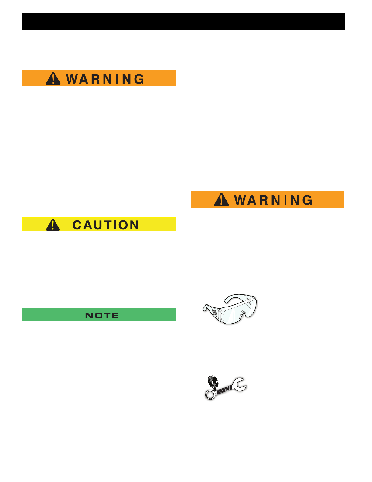
Wear eye protection
when working on the
vehicle. Use extra care
when working ar ound
batteries, or usin g so lvents or compressed air.
To reduce the possibility of causing a n
electrical arc, which could result in a battery
explosion, tur n off all el ec tric a l load s fr om
the battery before removing battery wires.
Wrap wrenches with vinyl
tape to reduce the possibility of a dropped wrench
‘shorting out’ a battery,
which could result in an
explosion.
Page A-2
Repair and Service Manual
GENERAL INFORMATION & ROUTINE MAINTENANCE
Read all of this manual to become thoroughly familiar with this vehicle. Pay particular attention to all Notes, Cautions and Warnings.
B
ROUTINE MAINTENANCE
This vehicle will give years of s atis facto ry ser vice pr oviding it receives regular maintena nce. Refe r to the Periodic Service Schedule for service i nterval s.
REAR AXLE
The only maintenance required for the first five y ears or
1000 hours of operation is to check the Torque to Rotate
(TTR) and the periodic inspection of the lubricant level.
Unless leakage is evident, the lubricant need onl y be
replaced after five years.
TIRES
The condition of the tires should be in spec ted dai ly, inflation pressures should be checked at leas t onc e a
week when the tires are cool. All dust caps for the
valves need to be reinstalled after checking the tire
pressure. For additional information, refer to the section
on TIRES AND WHEELS.
VEHICLE CLEANING AND CARE
Removal of oil, tar, asphalt, shoe polish, etc., requires
the use of a commercially available viny l/rubber clea ner.
The painted surfaces of the vehicle provide attrac tive
appearance and durable protection. Frequent washing
with lukewarm or cold water and mild detergen t is required to preserve the painted surfaces.
Occasional cleaning and waxing with non-abr asi ve
products designed for ‘clear coat’ automotiv e fini shes
will enhance the appearance and durability of the painted surfaces.
Corrosive materials used as fertilizers or for dust control
can collect on the underbody of the vehicle. T hese
materials will cause corrosion of underbody parts unless
flushed occasionally with plain water. Thoroughly clean
any areas where mud or other debris ca n collec t. Sedi ment packed in closed areas should be loosened to
ease its removal, taking care not to chip or otherwise
damage paint.
SUN TOP AND WINDSHIELD
The sun top does not provide protection from
roll-over or falling objects.
B
To reduce the possibility of severe injury or
vehicle damage, read and understand all
instructions s upp lie d b y th e manu f act ure r of
the pressure washer.
When pressure washing the exterior of the vehicle, do
not use pressure in excess of 700 psi. To reduce the
possibility of cosmetic damage, do not use any abrasive or reactive solvents to clean plastic parts.
It is important that proper techniques and cleaning materials be used. Using excessive water press ure may
cause severe injury to the operator or by stander, damage to the seals, plastics, seat material, body fini sh or
electrical system. Do not use pressure in exc ess of 700
psi to wash the exterior of the vehicle.
Clean the windshield with lots of water, a mild soap and
a clean cloth.
Normal cleaning of vinyl seats and plastic or rubber trim
requires the use of a mild soap soluti on app lied wi th a
sponge or soft brush and wiped with a damp cloth.
The windshield d oe s no t pro v ide pr ot e cti on
from tree limbs or flying objects.
The sun top and windshield provide some protec tion
from the elements; however, they will not keep the operator and passenger dry in a downpour. This vehicle is
not equipped with seat belts and the sun top has not
been designed to provide roll-over protection. In addition, the sun top does not protect against falli ng objects
nor does the windshield protect against flying obj ects
and tree limbs. Keep arms and legs inside of the vehicle
while it is moving.
HAULING
To reduce the possibility of severe injury or
death while transporting the vehicle:
Secure the vehicle and contents.
Never ride on the v ehicle being tran spo rt -
ed.
Always remove the windshield before trans-
Repair and Service Manual
Page A-3
GENERAL INFORMATION & ROUTINE MAINTENANCE
Read all of this manual to become thoroughly familiar with this vehicle. Pay particular attention to all Notes, Cautions and Warnings.
porting.
B
Maximum speed with sun top inst alled is 50
mph (80 kph).
If the vehicle is to be transported at highway speeds, the
sun top must be removed and the seat bottom sec ured.
When transporting vehicle below highway speed s,
check for tightness of hardware and cracks in sun top at
mounting points. Always remove windshield when tr ansporting. Always check that the vehicle and conte nts are
adequately secured before transporting. The r ated
capacity of the trailer or truck must exceed the weight of
the vehicle (see GENERAL SPECIFICATIONS for vehicle weight) and load plus 1000 lbs. (454 kg). Secure the
vehicle using ratchet tie downs.
T
HARDWARE
Periodically, the vehicle should be inspected for loose
fasteners. Fasteners should be tightened in accordance
with the Torque Specifications table (Ref. Fig. 7).
Use care when tightening fasteners and refer to the
Technician’s Repair and Service Manual for specific
torque values.
Generally, three classes of standard hardware and two
classes of metric hardware are used in the v ehic le.
Grade 5 hardware can be identified by the th ree m arks
on the hexagonal head and grade 8 hardware is identified by 6 marks on the head. Metric hardware is marked
on the head with 8.8 or 10.9. Unmarked hardware is
Grade 2.
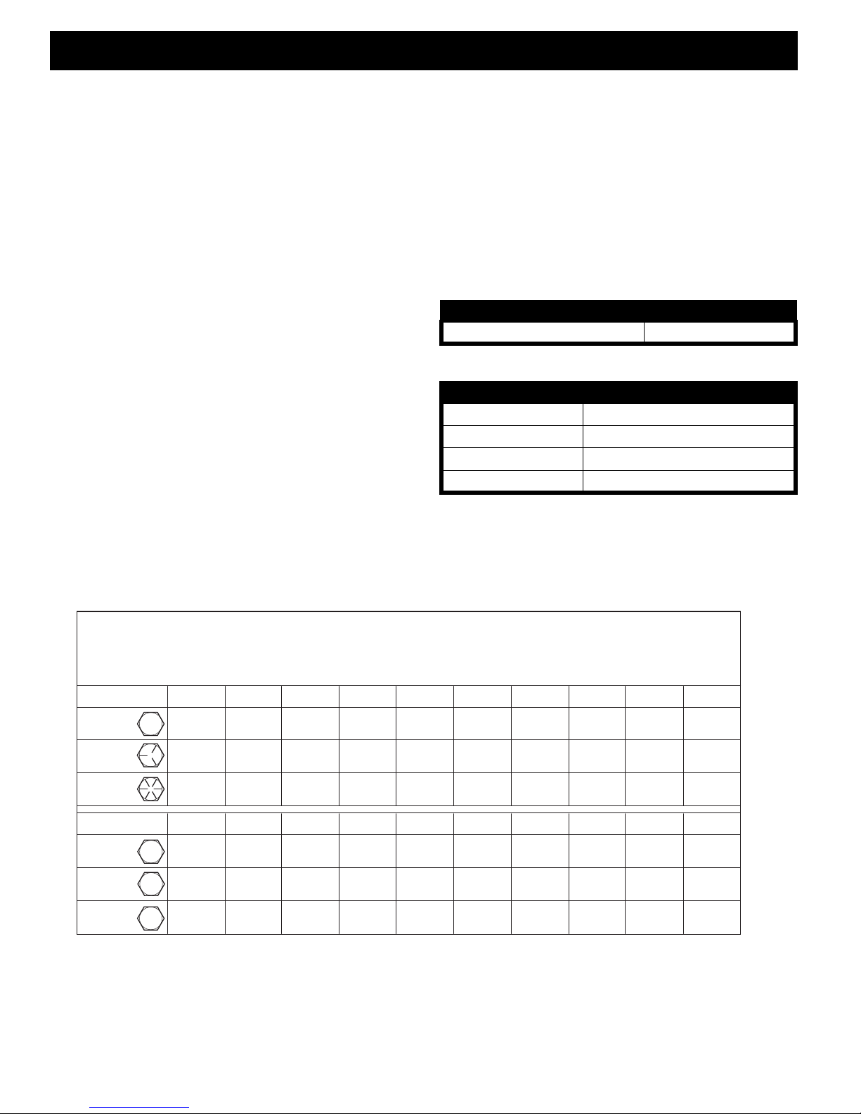
CAPACITIES AND REPLACEMENT PARTS
FLUID QUANTITY
Rear Axle Lubricant Mobile 424 25 oz. (739 ml)
Fig. 5 Capacities
ITEM PART NUMBER
Fuse ATC 10A (E-Z-GO P/N 35212G07)
Headlight Bulb 894 (E-Z-GO P/N 74004G01)
Turn Signal Bulb 912-NA (E-Z-GO P/N 74005G01)
Tail Light Bulb 2057 (E-Z-GO P/N 604311)
Fig. 6 Replacement Part
BOLT SIZE
Grade 2
Grade 5
Grade 8
BOLT SIZE
Class 5.8
(Grade 2)
Class 8.8
(Grade 5)
Class 10.9
(Grade 8)
5.8
8.8
10.9
ALL TORQUE FIGURES ARE IN FT. LBS. (Nm)
Unless otherwise noted in text, tighten all hardware in accordance with this chart.
This chart specifies 'lubricated' torque figures. Fasteners that are plated or lubricated when
installed are considered 'wet' and require approximately 80% of the torque required for 'dry' fasteners.
1/4" 5/16" 3/8" 7/16" 1/2" 9/16" 5/8" 3/4" 7/8" 1"
4
(5)
6
(8)
6
(8)
M4 M5 M6 M8 M10 M12 M14
1
(2)
2
(3)
3
(4)
8
(11)
13
(18)
18
(24)
2
(3)
4
(6)
6
(8)
15
(20)
23
(31)
35
(47)
4
(6)
7
(10)
10
(14)
24
(33)
35
(47)
55
(75)
10
(14)
18
(24)
25
(34)
35
(47)
55
(75)
80
(108)
20
(27)
35
(47)
49
(66)
55
(75)
80
(108)
110
(149)
35
(47)
61
(83)
86
(1
17)
75
(102)
110
(149)
170
(230)
55
(76.4)
97
(131)
136
(184)
130
(176)
200
(271)
280
(380)
125
(169)
320
(434)
460
(624)
190
(258)
480
(651)
680
(922)
Fig. 7 Torque Specifications and Bolt Grades
Page A-4
Repair and Service Manual

GENERAL INFORMATION & ROUTINE MAINTENANCE
Read all of this manual to become thoroughly familiar with this vehicle. Pay particular attention to all Notes, Cautions and Warnings.
PERIODIC SERVICE SCHEDULE
✓ - CHECK C&A - CHECK & ADJUST CL - CLEAN R - REPLACE
REMARKS
20 rnds/20 hrs
100 miles/160 kms
MONTHLY
60 rnds/60 hrs
300 miles/500 kms
QUARTERLY
125 rnds/125 hrs
600miles/1000 kms
SEMI-ANNUAL
250 rnds/250 hrs
1200miles/2000 kms
ANNUAL
5 YEARS
PAGE
9
Tires - pressure, condition of tires & rims
before eac h us e
DAILY
✓✓✓✓✓
B
B
Hardware - loose or missing
Reverse Warning Indicator
Overall Vehicle Condition
Batteries - state of charg e, cond ition, loose t erminal s, corr o-
sion, hold down & hardware
Batteries* - check electrolyte level, fill if required C&A C&A C&A C&A 18
Brakes - smooth operation of pedal, stopping distance
Brakes - aggressive stop test, does brake hold on a hill ✓✓✓✓
Accelerator - smooth operation
Wiring - loose connections, broken or missing insulation
Charger Receptacle - clean connections CL CL CL CL
Steering Assembly - excessive play, loose or missing hard-
ware
Tie Rods - excessive play, bent rods, loose or missing hard-
ware
Rear Axle - oil leakage, noise, loose or missing hardware
Rear Axle - drain & replace fluid R14
Front Suspension - strut oil leakage, excessive play in hubs
or kingpins, worn bushings, loose or missing hardware
Front Wheel Alignment - unusual tire wear C&A C&A C&A
Rear Suspension - shock oil leakage, worn bushings, loose
or missing hardware
✓✓✓✓✓
✓✓✓✓✓
✓✓✓✓✓
CL CL CL CL 17
✓
✓✓✓✓✓
✓✓✓✓✓
✓✓✓✓
✓✓✓✓
✓✓✓✓
✓✓✓✓
✓✓✓✓
✓✓✓
14
*Use only distilled or purified water that is free o f contaminants to fill batteries.
Fig. 8 Periodic Service Schedule
Repair and Service Manual
Page A-5

GENERAL INFORMATION & ROUTINE MAINTENANCE
Read all of this manual to become thoroughly familiar with this vehicle. Pay particular attention to all Notes, Cautions and Warnings.
Notes:
Page A-6
Repair and Service Manual

SAFETY
TABLE OF CONTENTS FO R SECT ION ‘B’
SECTION TITLE PAGE NO.
NOTES, CAUTIONS AND WARNINGS.....................................................................B - 1
IMPORTANT SAFETY WARNING ............................................................................B - 1
MODIFICATIONS TO VEHICLE................................................................................B - 1
GENERAL MAINTENANCE ..................................................................................... B - 1
BEFORE SERVICING THE VEHICLE.......................................................................B - 1
Additional Warnings.........................................................................................B - 2
BATTERY REMOVAL AND INSTALLATION.............................................................B - 3
LIFTING THE VEHICLE ............................................................................................B - 5
LIST OF ILLUSTRATIONS
Fig. 1 Attach Accessory Wires to B att ery Pack ......................... ... ... ....... ... ... ... ... ... . B - 2
Fig. 2 Batteries, Charg er Recept acle & Contr oller ........ ... ... ... ... ... ...... .... ... ... ... ...... . B - 3
Fig. 3 Battery Removal........... ...... .... ... ... ... ...... ... ... .... ... ...... ... ... ... ... ....... ... ... ... ... .... B - 4
Fig. 4 Battery Placement & Orien tatio n... ... ...... ... ... .... ... ... ...... ... ... ... ... ....... ... ... ... ... . B - 4
Fig. 5 Battery Hold Do wn........ ... ... .... ...... ... ... ... ... ....... ... ... ... ... ...... ... ... .... ... ... ...... ... . B - 5
Fig. 6 Battery Connections ........... .... ...... ... ... ... ... ....... ... ... ... ... ...... ... ... .... ... ...... ... ... . B - 5
Fig. 7 Lifting Points........... ... ...... ... .... ... ... ...... ... ... ... .... ... ...... ... ... ... ... ....... ... ... ... ... .... B - 6
Repair and Service Manual
Page B-i

SAFETY
Read all of Section B and this section before attempting any procedure. Pay particular attention to all Notes, Cautions and Warnings.
Notes:
Page B-ii
Repair and Service Manual
SAFETY
Read all of Section A and this section before attempting any procedure. Pay particular attention to all Notes, Cautions and Warnings.
NOTES, CAUTIONS AND WARNINGS
Throughout this manual, the following NOTES, CAUTIONS AND W ARNINGS are used. For the protection of
all personnel and the vehicle, be aware of and obser ve
the following:
Changes to the weight distribution or the center of gravity may make the vehicle unstable or
prone to roll over which could result in injury or
death to the oper at or or p asse ng e r(s).
B
B
A NOTE indicates a condit io n th at shoul d be obse rve d.
A CAUTION indicates a condition that may result in
damage to the vehicle or surrounding facilities.
A WARNING indicates a hazardous condition
which could result in serious injury or death.
IMPORTANT SAFETY WARNING
In any product, components will eventu ally fail to perform
properly as the result of normal use, age, wear or abuse.
It is virtually impossible to anticipate all possible component failures or the manner in which each component
may fail.
Be aware that a vehicle requiring repair indi cate s that
the vehicle is no longer functioning as des igne d and
therefore should be considered potentially haz ar dous.
Use extreme care when working on any vehicle . When
diagnosing, removing or replacing any com ponents that
are not operating correctly, take the time to consider the
safety ramifications if the component should move unexpectedly.
Some components are heavy, spring loaded, highly corrosive, explosive or may produce high amperage or
reach high temperatures. Gasoline, carbon monoxide,
battery acid and hydrogen gas could result i n ser ious
bodily injury to the technician/mechani c and b ystanders
if not treated with utmost caution. Be careful not to place
hands, face, feet or body in a location that could expose
them to injury should an unforeseen situation occ ur.
Always use the appropriate tools listed i n the tool list
and wear approved safety equipment.
GENERAL MAINTENANCE
When any maintenance procedure or ins pecti on is per formed, it is important that care be exercised to i nsu re
the safety of the technician/mechanic or bystanders and
to prevent damage to the vehicle.
Always read and understand the entire relevant manual
section (chapter) before attempting any inspe ctio n or
service.
BEFORE SERVICING THE VEHICLE
Before attempting to inspect or service a vehicle, be sure
to read and understand the following warnings:
To prevent personal injury or death, observe
the following:
Before working on the vehicle, remove all
jewelry (rings, watch, necklaces, etc.).
Be sure that no loose clothing or hair can
become caught in th e m ovin g p ar ts o f th e
powertrain.
Use care not to contact hot objects.
Before attempting to operate or adjust the
powertrain, the re ar of the ve hicl e mu st b e
raised and suppo rt ed on j ack s tan ds .
Wear OSHA approved clothing and eye
protection when working on anything that
could expose the body or eyes to potential
injury. In particular, use care when workin g
with or around ba tteries, compre ssed air or
solvents.
Always turn the key switch to ‘OFF’ and
remove the key before disconnecting a live
circuit.
MODIFICATIONS TO VEHICLE
Do not modify the vehicle in any manner that will change
the weight distribution of the vehicle.
When connecting battery cables, pay particular attention to the polarity of the battery
terminals. Never confuse the positive and
negative cables.
Repair and Service Manual
Page B-1
SAFETY
ATTACH NEGATIVE WIRE
FROM ACCESSORY TO
(-) BATTERY TERMINAL
ATTACH POWER WIRE
FROM ACCESSORY TO
(+) BATTERY TERMINAL
Read all of Section A and this section before attempting any procedure. Pay particular attention to all Notes, Cautions and Warnings.
If repairs are to be made that will require
B
welding or cutting, the batteries must be
removed.
Additional Warnings
Before working on the electrical system, be sure to read
and understand the following warnings that pertain to
the electrical system repair or maintenanc e.
To prevent expl osio n t hat cou ld res ult in
severe personal injury or death, keep all smoking materials, op en fla me or s pa rks aw ay f rom
gasoline and b att e ries .
Hydrogen gas is ge ne ra ted in the cha rg in g
cycle of batteries and is explosive in concentrations as low as 4%. Because hydrogen gas is lighter than air, it will collect in
the ceiling of buildings necessitating proper
ventilation. Five air exchanges per hour is
considered the minimum requirement.
Be sure that the key switch is off and all
electrical acce s sor ies a re tu rned of f be fo re
starting work on vehicle.
The batteries should always be removed
before any servicing or repairs that will generate sparks.
Never disconn ect a circ ui t un de r load at a
battery terminal.
Any electrolyte spills should be neutra lized
with a solutio n of 1/4 c u p (60 ml) s od iu m
bicarbonate (baking soda) dissolved in 1 1/
2 gallons (6 liters) of wate r and flush ed with
water.
Overfilling batteries may result in electrolyte
being expelled from the battery during the
charge cycle. Expelled electrolyte may
cause damage to the vehicle and storage
facility.
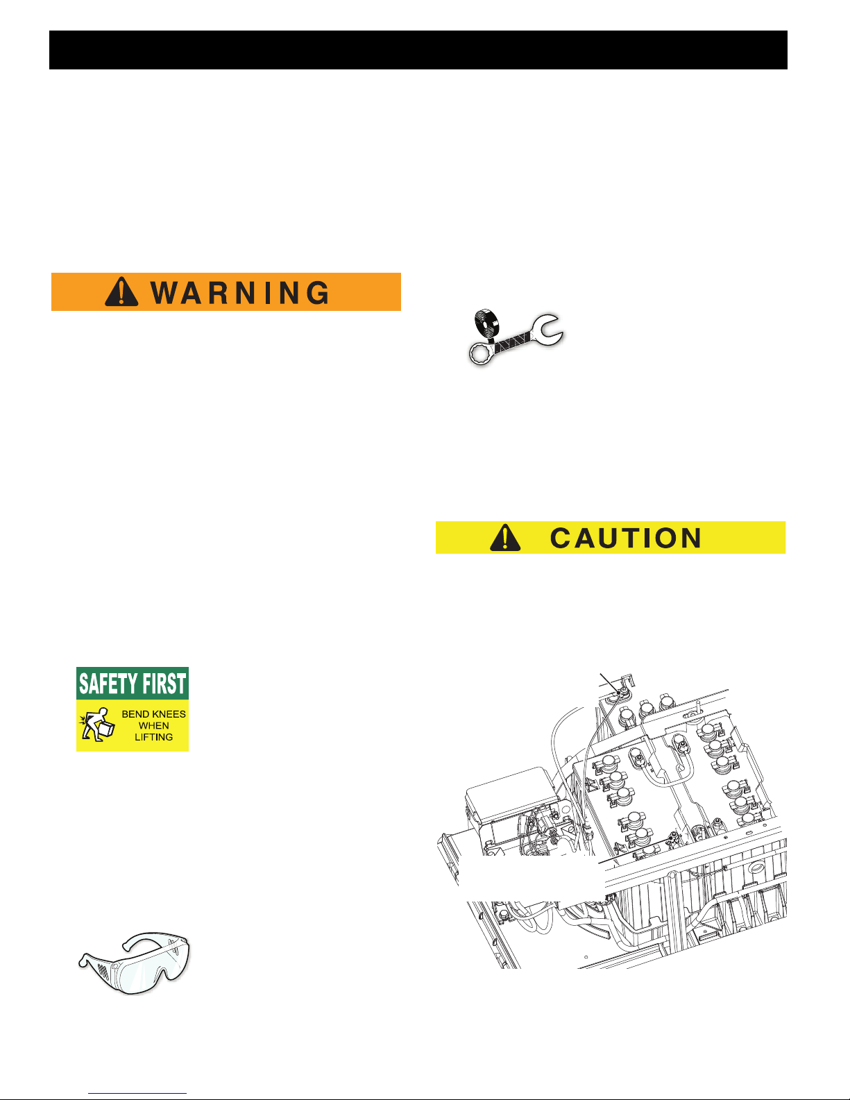
Wrap wrenches with vinyl
tape to prevent the possibility of a drop pe d wren c h
’shorting out’ a battery,
which could result in an
explosion and severe personal injury or
death.
Aerosol contai ners of b att er y termin a l protectant must be used with extreme care.
Insulate metal container to prevent can
from contacting battery terminals which
could result in an exp lo sion .
ALL accessories that do NOT use the accessory wiring
harness MUST be connected to draw fr om the entire 48
Volt battery pack. T he Operation al Performance G uarantee of 2 rounds per day shall be void in non-factory accessories that use more than 1 Amp/Hour of energy per
round are installed on the vehicle.
to tip batteries excessively when removing
or installing them; spilled electro lyte can
cause burns and damage.
The electro lyt e in a st or ag e b att er y is an
acid solution which can cause severe burns
to the skin and eyes. Treat all electrolyte
spills to the body and eyes with extended
flushing with clear water. Contact a physician immediately.
Page B-2
Batteries are heavy. Use
proper lifting techniques
when moving them. Always
lift the battery with a commercially available battery
lifting device. Use care not
Always wear a safety
shield or approved safet y
goggles when ad ding water
or charging batteries.
Repair and Service Manual
Fig. 1 Attach Accessory Wires to Battery Pack
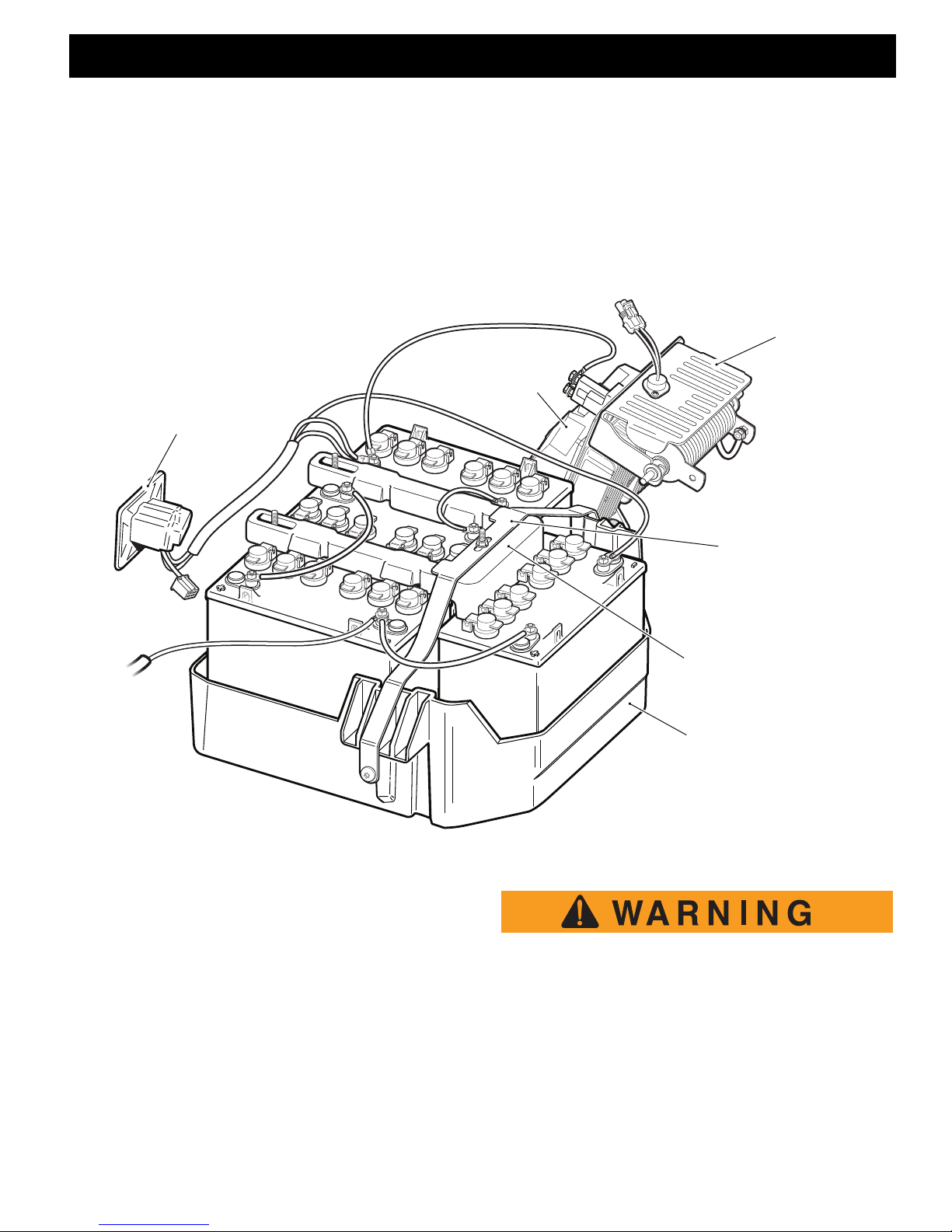
SAFETY
CHARGER RECEPTACLE
CONTROLLER
RESISTOR
BATTERY HOLD DOWN
BATTERY STRAP
BATTERY TRAY
Read all of Section A and this section before attempting any procedure. Pay particular attention to all Notes, Cautions and Warnings.
B
Accessories connected to this vehi cl e that do no t use
the accessory harness must be conne cted a cr oss the
entire 48 volt battery pack. This can be done by connecting to the two battery terminals shown in Figure 1.
This can be done by connecting to the two battery terminals shown in the illustration.(Ref. F ig. 10) If the ac cessory requires voltage other than 48 volts a DC to DC
converter must be used to change the vo ltage to the
amount required by the accessory. A DC to DC converter is available through E-Z-GO S ervic e Par ts.
The Operational Performance Guarantee o f 2 rou nds
per day shall be void if non-factory accessories that use
more than 1 Amp/Hour of energy per round are installed
on the vehicle.
B
BATTER Y REMOVAL & INSTALLATION
Tool List Qty.
Insulated Wrench, 9/16".............................................. 1
Socket, 1/2" Deep-well................................................ 1
Socket, 9/16"............................................................... 1
Torx Bit, 50 IP..............................................................1
Ratchet........................................................................ 1
Battery Carrier Strap ................................................... 2
Torque Wrench, in. lbs................................................. 1
Portable Lifting Device ................................................ 1
Fig. 2 Batteries, Charger Receptacle & Controller
When lifting a battery always use all 4 lifting
lugs provided. Do not attempt to lift a battery
with only one strap, this may break lifting lugs
and result in personal injury or damage to the
battery.
Repair and Service Manual
Page B-3
SAFETY
FRONT
Read all of Section A and this section before attempting any procedure. Pay particular attention to all Notes, Cautions and Warnings.
B
The following text, there are references to removing/installing
bolts, etc. Additional hardware (nuts, washers, etc.) that is
removed must always be installed in its original position unless
otherwise specified. Non-specified torques are as shown in the
table contained in Section ’A’.
1. Turn vehicle key to the off position and remove the
key.
2. Using an insulated wrench, disconnect the main negative (-) battery cable, BL-.
3. Using an insulate d wrench, disconnec t the mai n positive (+) battery cable, BL+.
4. Using an insulated wrench, disconnect and remove all
other wires connected to the batteries.
5. Remove the two pan head Torx screws, (one on each
side) from the battery strap.
6. Remove the battery hold down and the batter y strap
by loosening all three hex nuts until they are at the
end of the J-bolt and u nhooking the J-bolts from the
battery tray. When removing the J-bolts from between
the batteries it may help to tilt the ba ttery to the outside of the car to release the pressure on the J-bolt.
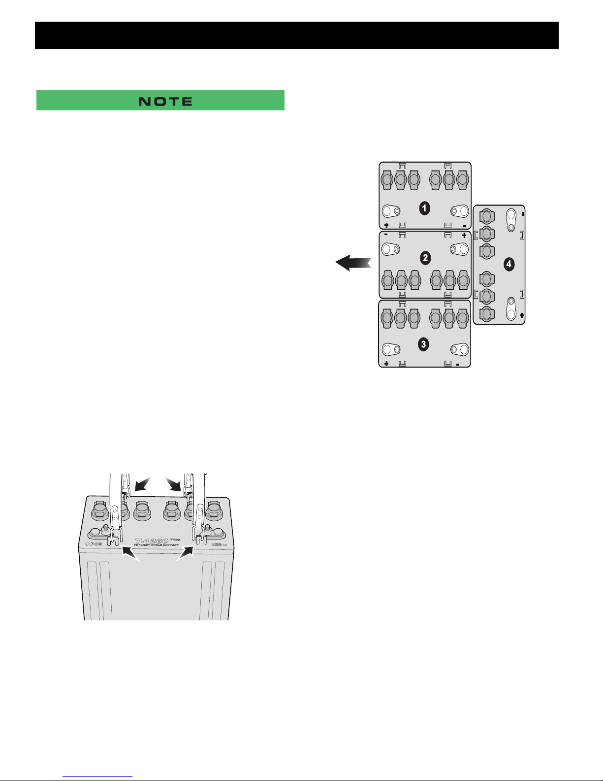
7. Remove the batteries using commercially available
battery carrier straps (2 per battery) and a portable lifting device. Remove the three front batteries (1, 2, & 3)
one at a time; then u sing the c arrier straps ti lt the la st
battery (4) to the front of the vehicle just enough to
clear the rear body and lift up and out of the vehicle.
Fig. 3 Battery Removal
8. Check the area surro unding the battery tra y for corrosion. If any corrosion is found, it should be immediately removed with a putty knife and a wire br ush (for
metal surfaces) or a plastic bristle brush (for plastic
surfaces). The area s hould be w ashed with a solution
of baking soda and water and dried thoroughly. All
metal surfaces that have been cleaned must be
primed and painted with a corrosion resistant paint.
9. Replace the batter ie s, starti ng with the batt ery l oc ate d
at the back of the ba tt ery t ray (4), maki ng su re th at i t is
positioned as shown
.
Fig. 4 Battery Placement & Orientation
10. With th e J-bolts in the battery hold do wn and held in
place by the hex n uts on the en d of the threa ded portion; carefully positio n the battery hold down and battery strap, guiding the J-bol ts between the batte ries (i t
may be necessary to tip th e batt eries sli ghtly) and into
the slots in the battery tr ay. Tighten the hex nuts on
the J-bolts making su re that the J-bolts are securely
hooked in the battery tray. Tighten the J-b olt hex nuts
to 62 - 80 in. lbs. (7 - 9 Nm) torque.
11. Install the two pan head Torx screws through the ends
of the battery strap into the hol es on the v ehi c le fram e
and tighten them to 80 - 97 in. lbs. (9 - 11 Nm) torque.
12. Inspect all wires and terminals and clean any corrosion from the battery terminals or wire terminals with a
solution of baking soda and water, use a wire brush to
completely remove corrosion if required.
13.Carefully replace the w ires on th e bat tery te rm in als as
shown. Make sure to reconnect the m ain negative (-)
battery cable, BL-, from the controller last.
Page B-4
Repair and Service Manual
SAFETY
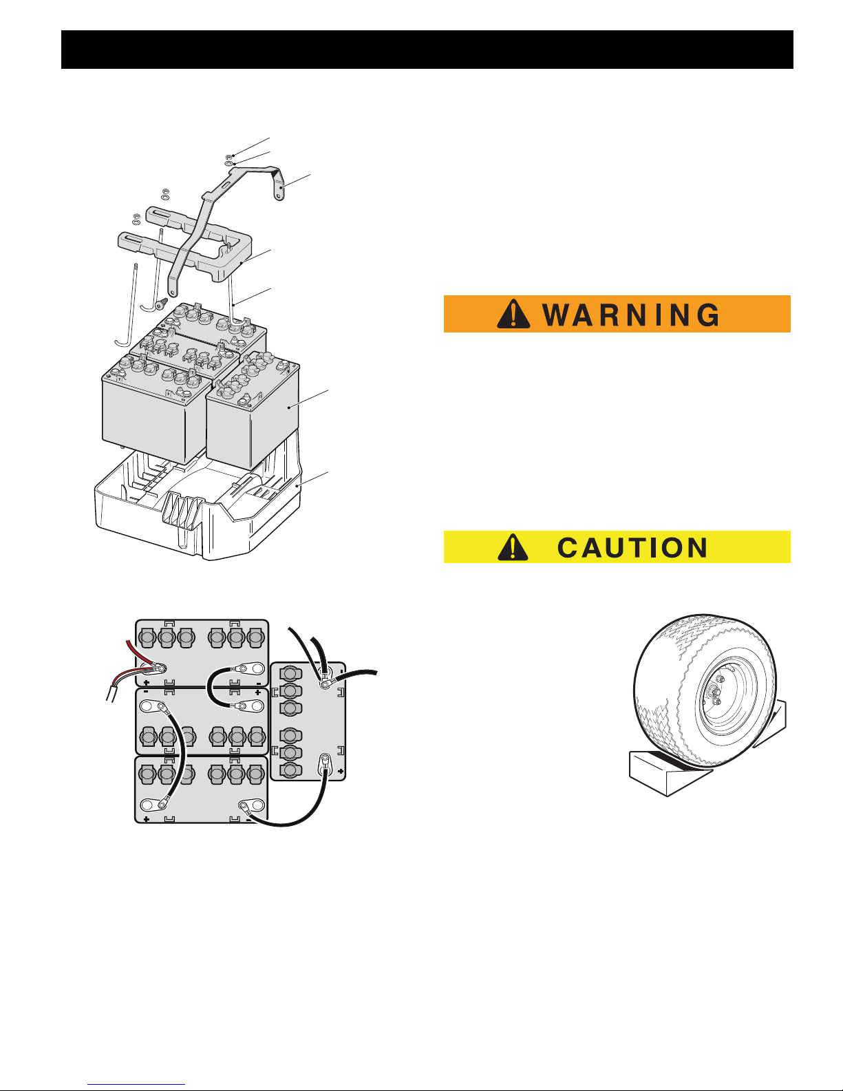
Hex Nut
Washer
Battery Hold Down
Battery Strap
J-bolt
Battery
Battery
Tray
Red and
Grey Wires
from
Charger
Receptacle
Black Wire from
Charger Receptacle
BL+ Red
Wire from
Solenoid
BL- Black Wire
from Controller
Black Wire
from
Harness
Read all of Section A and this section before attempting any procedure. Pay particular attention to all Notes, Cautions and Warnings.
B
LIFTING THE VEHICLE
Tool List Qty.
Floor Jack....................................................................1
Jack Stands.................................................................4
Wheel Chocks..............................................................4
Some servicing operations may require the front, rear or
the entire vehicle to be raised.
To prevent possible injury or death resulting
from a vehicle falling from a jack, be sure the
vehicle is on a firm and level surface. Never
get under a vehi cl e while it is su ppo rt ed by a
jack. Use jack stands and test the stability of
the vehicle on the stands. Always place wheel
chocks in front and behind the wheels not
being raised. Use extreme care since the vehicle is extremely unstable during the lifting process.
B
Fig. 5 Battery Hold Down
Fig. 6 Battery Connections
14. Tighten all battery terminal hardware to 95 - 105 in.
lbs. (11 - 12 Nm) torque.
15. Protect the battery terminals and battery cable ends
with a commercially available protective coating.
Repair and Service Manual
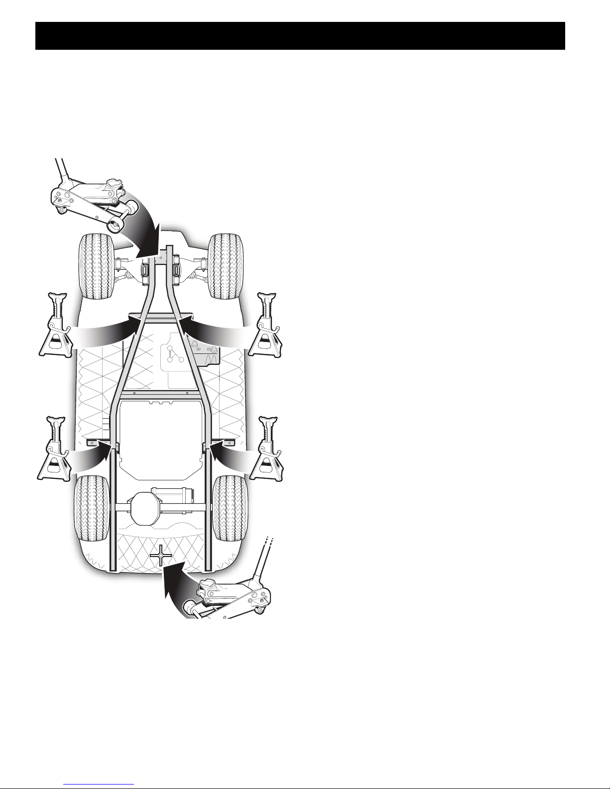
When lifting the vehicle, position jack stands only in the
areas indicated.
To raise the entire vehicle,
install the wheel chocks in
front and behind each front
wheel. Center the jack
under the bagwell, place a
piece of wood, approximately 2" x 4" x 12",
between the jack and the
underside of the bagwell,
raise the vehicle and position the jack stands under
the frame where the leaf
spring mounting bracket is
welded to the frame.
Lower the jack and test the stability of the vehicle on the
two jack stands.
Place the jack under the center front of the car just
behind the bumper. Raise the vehicle and position the
jack stands under the frame where the instrument panel
support is attached to the frame as shown.
Lower the jack and test the stability of the vehic le on a ll
four jack stands.
Page B-5
SAFETY
Read all of Section A and this section before attempting any procedure. Pay particular attention to all Notes, Cautions and Warnings.
To raise only the front or rear of the vehicle, place the
wheel chocks in front and behind the rear wheels. T he
B
jack may be left under the center front of the frame while
the front end of the vehicle is on the jack stands.
Lower the vehicle by reversing the lifting se quence.
Fig. 7 Lifting Points
Page B-6
Repair and Service Manual

SAFETY
Read all of Section A and this section before attempting any procedure. Pay particular attention to all Notes, Cautions and Warnings.
Notes:
Repair and Service Manual
Page B-7

SAFETY
Read all of Section A and this section before attempting any procedure. Pay particular attention to all Notes, Cautions and Warnings.
Notes:
Page B-8
Repair and Service Manual

BODY
TABLE OF CONTENTS FOR SECTION ‘C’
SECTION TITLE PAGE NO.
BODY........................................................................................................................ C - 1
General ............................................................................................................ C - 1
BODY COMPONENT REPLACEMENT ....................................................................C - 2
Front Bumper................................................................................................... C - 2
Rocker Panels.................................................................................................. C - 2
Floor Mat..........................................................................................................C - 2
Cowl and Instrument Panel .............................................................................. C - 3
Front Splash Guard..........................................................................................C - 4
Sweater Basket................................................................................................C - 5
Seat Back Assembly ........................................................................................ C - 5
Fender Liner.....................................................................................................C - 6
Rear Body........................................................................................................ C - 6
Rear Bumper....................................................................................................C - 6
2 + 2 Rear Facing Seat & Foot REst ................................................................C - 7
Floorboard......................................................................................................C - 10
BODY CARE AND MAINTENANCE ....................................................................... C - 11
Cleaning......................................................................................................... C - 11
PAINTING ............................................................................................................... C - 11
Light Scratches .............................................................................................. C - 11
Minor Scratches.............................................................................................C - 11
Larger Scratches............................................................................................C - 12
Complete Panel Repair ..................................................................................C - 12
LIST OF ILLUSTRATIONS
Fig. 1 Body ......................................................................................................... C - 1
Fig. 2 Christmas Tree Rivet Removal ................................................................. C - 1
Fig. 3 Front Bumper ........................................................................................... C - 2
Fig. 4 Rocker Panel Removal ............................................................................. C - 2
Fig. 5 Floor Mat Fastener Removal ....................................................................C - 3
Fig. 6 Floor Mat .................................................................................................. C - 3
Fig. 7 Cowl and Instrument Panel Trim ............................................................... C - 3
Fig. 8 Instrument Panel and Cup Holder ............................................................C - 4
Fig. 9 Front Splash Guard .................................................................................. C - 4
Fig. 10 Rear Body, Sweater Basket, Rear Bumper & Fender Liner ....................... C - 5
Fig. 11 2 + 2 Rear Facing Seat & Foot Rest ......................................................... C - 7
Fig. 12 Rear Facing Seat Bottom.......................................................................... C - 7
Fig. 13 Rear Facing Seat Back .............................................................................C - 8
Fig. 14 Rear Facing Seat Hip Restraint ................................................................ C - 8
Fig. 15 Upper Hip Restraint Bolts ......................................................................... C - 8
Fig. 16 Front Seat Back........................................................................................ C - 8
Fig. 17 Rear Facing Seat Foot Rest ..................................................................... C - 8
Fig. 18 Foot Rest Removal ................................................................................... C - 9
Fig. 19 Seat Back Support.................................................................................... C - 9
Fig. 20 Front Seat Support and Floorboard......................................................... C - 10
Repair and Service Manual
Page C-i

BODY
Read all of Section B and this section before attempting any procedure. Pay particular attention to all Notes, Cautions and Warnings.
Notes:
Page C-ii
Repair and Service Manual
 Loading...