

Ezgo REFRESHER 1200 CARB Owner's Manual And Service Manual

OWNER’S MANUAL
AND SERVICE GUIDE
BEDIENUNGS- UND
WARTUNGSHANDBUCH
606907-DE
GASOLINE POWERED REFRESHMENT VEHICLE
ERFRISCHUNGSFAHRZEUG MIT BENZINMOTOR
ISSUED APRIL 2008
AUSGABE APRIL 2008
SAFETY
WASH HANDS
AFTER HANDLING!
Battery posts,
terminals and related
accessories contain
lead and lead compounds,
chemicals known
to cause cancer and
reproductive harm.
BATTERY WARNING
WASH HANDS
AFTER HANDLING!
WARNING: Battery posts, terminals and related
accessories contain lead and lead compounds,
chemicals known to cause cancer and reproductive harm.
BATTERIES
CONTAIN LEAD
AND RELATED PARTS
!
<
14
˚
25
%
DO NOT
DRIVE ACROSS
SLOPES IN
EXCESS OF 14˚
Ce système d'allumage par étincelle de véhicule respecte
toutes les exigences du Règlement sur le matériel brouilleur
du Canada.
For any questions on material contained in this manual, contact an authorized representative for clarification.
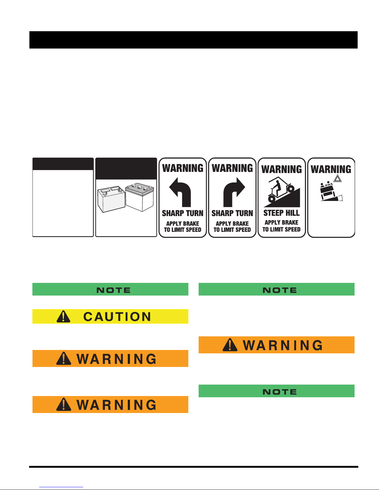
Read and understand all labels located on the vehicle. Always replace any damaged or missing labels.
On steep hills it is possible for vehicles to coast at greater than normal speeds encountered on a flat surface. To pre-
vent loss of vehicle control and possible serious injury, speeds should be limited to no more than the maximum speed
on level ground. See GENERAL SPECIFICATIONS. Limit speed by applying the service brake.
Catastrophic damage to the drivetrain components due to excessive speed may result from driving the vehicle above
specified speed. Damage caused by excessive speed may cause a loss of vehicle control, is costly, is considered
abuse and will not be covered under warranty.
For towing/transporting vehicle, refer to “TRANSPORTING VEHICLE”.
Signs similar to the ones illustrated should be used to warn of situations that could result in an unsafe condition.
Be sure that this manual remains as part of the permanent service record should the vehicle be sold. Throughout this
guide NOTE, CAUTION and WARNING will be used.
Observe these NOTES, CAUTIONS and WARNINGS; be aware that servicing a vehicle requires mechanical skill and
a regard for conditions that could be hazardous. Improper service or repair may damage the vehicle or render it unsafe.
A NOTE indicates a condition that should be observed.
A CAUTION indicates a condition that may result in
damage to the vehicle.
A WARNING indicates a hazardous condition
that could result in severe injury or death.
Engine exhaust from this product contains
chemicals known, in certain quantities, to
cause cancer, birth defects, or other reproductive harm.
(NOTES, CAUTIONS AND WARNINGS CONTINUED ON INSIDE OF BACK COVER)
The exhaust emissions of this vehicles’ engine complies with
regulations set forth by the Environmental Protection Agency
(EPA) of the United States of America (USA) at time of manufacture. Significant fines could result from modifications or tampering with the engine, fuel, ignition or air intake systems.
Battery posts, terminals and related accessories contain lead and lead compounds. Wash
hands after handling.
This spark ignition system meets all requirements of the Canadian Interference-Causing Equipment Regulations.

OWNER’S MANUAL
AND SERVICE GUIDE
GASOLINE POWERED
REFRESHMENT VEHICLE
REFRESHER® 1200
®
REFRESHER
1200 CARB
The E-Z-GO Division of Textron Inc. reserves the right to incorporate engineering and design changes to products in this Manual, without obligation to include
these changes on units leased/sold previously.
The information contained in this Manual may be revised periodically by the E-Z-GO Division, and therefore is subject to change without notice.
The E-Z-GO Division DISCLAIMS LIABLITY FOR ERRORS IN THIS MANUAL, and the E-Z-GO Division SPECIFICALLY DISCLAIMS LIABILITY FOR INCI-
DENTAL AND CONSEQUENTIAL DAMAGES resulting from the use of the information and materials in this Manual.
TO CONTACT US
NORTH AMERICA:
TECHNICAL ASSISTANCE & WARRANTY PHONE: 1-800-774-3946, FAX: 1-800-448-8124
SERVICE PARTS PHONE: 1-888-GET-EZGO (1-888-438-3946), FAX: 1-800-752-6175
INTERNATIONAL: PHONE: 001-706-798-4311, FAX: 001-706-771-4609
E-Z-GO DIVISION OF TEXTRON, INC., 1451 MARVIN GRIFFIN ROAD, AUGUSTA, GEORGIA USA 30906-3852
Starting Model Year 2008
Owner’s Manual and Service Guide
Page i

GENERAL INFORMATION
This vehicle has been designed and manufactured in the United States of America (USA) as a
‘World Vehicle’. The Standards and Specifications listed in the following text originate in the USA
unless otherwise indicated.
The use of non Original Equipment Manufacturer (OEM) approved parts may void the warranty.
Overfilling battery may void the warranty.
Tampering with or adjusting the governor to permit vehicle to operate at above factory specifications
will void the vehicle warranty.
When servicing engines, all adjustments and replacement components must be per original vehicle
specifications in order to maintain the United States of America Federal and State emission
certification applicable at the time of manufacture.
BATTERY PROLONGED STORAGE
All batteries will self discharge over time. The rate of self discharge varies depending on the
ambient temperature and the age and condition of the batteries.
A fully charged battery will not freeze in winter temperatures unless the temperature falls
below -75° F (-60° C).
Page ii
Owner’s Manual and Service Guide

TABLE OF CONTENTS
SAFETY ............................................................................................................INSIDE COVERS
GENERAL INFORMATION ........................................................................................................II
SAFETY INFORMATION ......................................................................................................... VII
REFRESHMENT UNIT ...............................................................................................................1
MOUNT VENDING UNIT TO REFRESHMENT VEHICLE ................................................................................. 1
FRONT STRUT INSTALLATION ....................................................................................................................... 1
WINDSHIELD AND MIRROR INSTALLATION ................................................................................................... 1
Fig. 1 Mounting the Refreshment Unit ................................................................................................ 2
CANOPY FRAME INSTALLATION .................................................................................................................... 2
CANOPY INSTALLATION .................................................................................................................................. 2
Fig. 2 Front Strut, Windshield and Mirror Installation ..........................................................................3
DRAIN VALVE INSTALLATION .......................................................................................................................... 3
REFRESHMENT UNIT REMOVAL ..................................................................................................................... 3
REFRESHMENT UNIT OPERATION, MAINTENANCE AND CLEANING ......................................................... 3
Operation ............................................................................................................................................... 3
Fig. 3 Canopy Instfallation ................................................................................................................... 4
Cleaning ................................................................................................................................................. 5
Fig. 4 Emptying Water from Bins ........................................................................................................ 5
Maintenance ........................................................................................................................................... 5
REFRESHMENT UNIT REPLACEMENT PARTS .............................................................................................. 5
BEFORE INITIAL USE ...............................................................................................................5
Fig. 5 Initial Service Chart ................................................................................................................... 6
CONTROLS AND INDICATORS ................................................................................................6
KEY/LIGHT SWITCH .......................................................................................................................................... 6
Fig. 6 Key/Light Switch, Low Oil Pressure Light and Fuel Gauge ....................................................... 6
DIRECTION SELECTOR .................................................................................................................................... 6
CHOKE ............................................................................................................................................................... 6
Fig. 7 Direction Selector ...................................................................................................................... 6
FUEL GAUGE ..................................................................................................................................................... 6
Fig. 8 Choke ........................................................................................................................................ 7
LOW OIL PRESSURE INDICATOR LIGHT ........................................................................................................ 7
ACCELERATOR PEDAL .................................................................................................................................... 7
Fig. 9 Accelerator and Brake Controls ................................................................................................ 7
COMBINATION SERVICE AND PARK BRAKE PEDAL...................................................................................... 7
FRONT DISC BRAKES (OPTIONAL) ................................................................................................................. 7
HORN .................................................................................................................................................................. 8
Fig. 10 Horn Button ............................................................................................................................... 8
OPERATING THE VEHICLE ......................................................................................................8
RUN-IN ................................................................................................................................................................ 8
Fig. 11 Check Oil Level on Dipstick ...................................................................................................... 9
COLD STARTING ............................................................................................................................................... 9
STARTING AND DRIVING ................................................................................................................................. 9
STARTING THE VEHICLE ON A HILL ............................................................................................................... 9
COASTING ....................................................................................................................................................... 10
FUEL ................................................................................................................................................................. 10
Fig. 12 Fueling .................................................................................................................................... 10
BATTERY .......................................................................................................................................................... 10
LABELS AND PICTOGRAMS ........................................................................................................................... 11
SUN TOP AND WINDSHIELD .......................................................................................................................... 11
12 VOLT POWER OUTLET .............................................................................................................................. 11
Fig. 13 12 Volt Power Outlet ............................................................................................................... 11
TOWING A TRAILER ........................................................................................................................................ 11
VEHICLE CLEANING AND CARE ...........................................................................................11
VEHICLE CLEANING ....................................................................................................................................... 11
Owner’s Manual and Service Guide
Page iii

TABLE OF CONTENTS
REPAIR ....................................................................................................................................12
LIFTING THE VEHICLE ....................................................................................................................................13
Fig. 14 Lifting the Vehicle .....................................................................................................................13
WHEELS AND TIRES .......................................................................................................................................13
Tire Repair ............................................................................................................................................13
Wheel Installation .................................................................................................................................14
Fig. 15 Wheel Installation .....................................................................................................................14
LIGHT BULB REPLACEMENT ..........................................................................................................................14
Fig. 16 Headlight and Turn Signal Bulb Replacement..........................................................................14
FUSE REPLACEMENT .....................................................................................................................................14
Fig. 17 Tail and Brake Light Bulb Replacement ...................................................................................15
VEHICLE WITH A DISCHARGED BATTERY ...................................................................................................15
TRANSPORTING VEHICLE .....................................................................................................15
TOWING ............................................................................................................................................................15
NEUTRAL LOCK ...............................................................................................................................................15
Fig. 18 Neutral Lock .............................................................................................................................15
HAULING ...........................................................................................................................................................16
SERVICE AND MAINTENANCE ..............................................................................................16
SERIAL NUMBER LABEL LOCATION ..............................................................................................................17
Fig. 19 Serial Number Plate Location...................................................................................................17
PERIODIC SERVICE SCHEDULE ...................................................................................................................18
Fig. 20 Periodic Service Schedule .......................................................................................................18
TIRE INSPECTION ............................................................................................................................................19
FOUR CYCLE ENGINE.............................................................................................................20
ENGINE SPECIFICATIONS...............................................................................................................................20
ENGINE DESCRIPTION ....................................................................................................................................20
CHECKING OIL LEVEL......................................................................................................................................20
Fig. 21 Clean Entire Dipstick.................................................................................................................20
Fig. 22 Check Oil Level on Dipstick......................................................................................................20
CHANGING THE OIL .........................................................................................................................................20
Fig. 23 Oil Viscosity Chart.....................................................................................................................21
Fig. 24 Cleaning Top of Engine ............................................................................................................21
Fig. 25 Remove Oil Filter......................................................................................................................21
Fig. 26 Inspect Oil Filter........................................................................................................................21
Fig. 27 Oil Drain Plug............................................................................................................................22
STARTER/GENERATOR BELT TENSION ........................................................................................................22
ADJUSTING THE BELT .....................................................................................................................................23
BATTERY CLEANING........................................................................................................................................23
BRAKES .............................................................................................................................................................24
PERIODIC BRAKE TEST FOR MECHANICAL BRAKES ..................................................................................24
AIR INTAKE AND COOLING FINS ....................................................................................................................25
REAR AXLE........................................................................................................................................................25
CHECKING THE LUBRICANT LEVEL...............................................................................................................25
AIR CLEANER INSPECTION AND REPLACEMENT ........................................................................................25
LUBRICATION....................................................................................................................................................26
SPARK PLUGS ..................................................................................................................................................27
DIRECTION SELECTOR....................................................................................................................................27
Fig. 28 Add Engine Oil.............................................................................................................22
Fig. 29 Check Belt Tension with Guage................................................................................................23
Fig. 30 Check Belt Tension Manually ...................................................................................................23
Fig. 31 Adjust Belt Tension...................................................................................................................23
Fig. 32 Preparing Acid Neutralizing Solution ........................................................................................24
Fig. 33 Typical Brake Performance Test...............................................................................................24
Fig. 34 Cleaning Cooling System with Air.............................................................................................25
Fig. 35 Add, Check and Drain Rear Axle Lubricant ..............................................................................26
Fig. 36 Air Cleaner ................................................................................................................................26
Fig. 37 Lubrication Points .....................................................................................................................27
Fig. 38 Gapping the Spark Plug...............................................................................................27
Page iv
Owner’s Manual and Service Guide

TABLE OF CONTENTS
PROLONGED STORAGE ..................................................................................................................................27
HARDWARE.......................................................................................................................................................28
Fig. 39 Torque Specifications and Bolt Grades ....................................................................................28
CAPACITIES AND REPLACEMENT PARTS.....................................................................................................29
Fig. 40 Capacities and Replacement Parts...........................................................................................29
GENERAL SPECIFICATIONS...................................................................................................31
Refresher 1200 ..................................................................................................................................................32
Fig. 41 Vehicle Dimensions .................................................................................................................33
Fig. 42 Vehicle Dimensions, Incline Specifications and Turning Clearance Diamete...................34
VEHICLE WARRANTIES ..........................................................................................................37
DOMESTIC WARRANTY (U.S. AND CANADA) ...............................................................................................38
INTERNATIONAL WARRANTY..........................................................................................................................39
VEHICLE WARRANTIES FEDERAL 2008 ........................................................................................................41
VEHICLE WARRANTIES CALIFORNIA 2008....................................................................................................43
DECLARATION OF CONFORMITY .........................................................................................45
LABELS AND PICTOGRAMS ...................................................................... APPENDIX A
Owner’s Manual and Service Guide
Page v

TABLE OF CONTENTS
NOTES:
Page vi
Owner’s Manual and Service Guide

SAFETY INFORMATION
This manual has been designed to assist in maintaining the vehicle in accordance with procedures developed by the
manufacturer. Adherence to these procedures and troubleshooting tips will ensure the best possible service from the
product. To reduce the chance of personal injury or property damage, the following must be carefully observed:
Certain replacement parts can be used independently and/or in combination with other accessories to modify an E-ZGO-manufactured vehicle to permit the vehicle to operate at or in excess of 20mph. When an E-Z-GO-manufactured
vehicle is modified in any way by the Distributor, Dealer or customer to operate at or in excess of 20mph, UNDER FEDERAL LAW the modified product will be a Low Speed Vehicle (LSV) subject to the strictures and requirements of Federal Motor Vehicle Safety Standard 571.500. In these instances, pursuant to Federal law the Distributor or Dealer MUST
equip the product with headlights, rear lights, turn signals, seat belts, top, horn and all other modifications for LSV’s
mandated in FMVSS 571.500, and affix a Vehicle Identification Number to the product in accordance with the requirements of FMVSS 571.565. Pursuant to FMVSS 571.500, and in accordance with the State laws applicable in the places
of sale and use of the product, the Distributor, Dealer or customer modifying the vehicle also will be the Final Vehicle
Manufacturer for the LSV, and required to title or register the vehicle as mandated by State law.
E-Z-GO will NOT approve Distributor, Dealer or customer modifications converting E-Z-GO products into LSV’s.
The Company, in addition, recommends that all E-Z-GO products sold as personal transportation vehicles BE OPER-
ATED ONLY BY PERSONS WITH VALID DRIVERS LICENSES, AND IN ACCORDANCE WITH APPLICABLE STATE
REQUIREMENTS. This restriction is important to the SAFE USE AND OPERATION of the product. On behalf of E-Z-
GO, I am directing that E-Z-GO Branch personnel, Distributors and Dealers advise all customers to adhere to this
SAFETY RESTRICTION, in connection with the use of all products, new and used, the Distributor or Dealer has reason
to believe may be operated in personal transportation applications.
Information on FMVSS 571.500 can be obtained at Title 49 of the Code of Federal Regulations, section 571.500, or
through the Internet at the website for the U.S. Department of Transportation - at Dockets and Regulation, then to Title
49 of the Code of Federal Regulations (Transportation).
GENERAL
Many vehicles are used for a variety of tasks beyond the original intended use of the vehicle; therefore, it is impossible
to anticipate and warn against every possible combination of circumstances that may occur. No warnings can take the
place of good common sense and prudent driving practices.
Good common sense and prudent driving practices do more to prevent accidents and injury than all of the warnings and
instructions combined. The manufacturer strongly suggests that all users and maintenance personnel read this entire
manual paying particular attention to the CAUTIONS and WARNINGS contained therein.
If you have any questions regarding this vehicle, contact your closest representative or write to the address on the back
cover of this publication, Attention: Product Service Department.
The manufacturer reserves the right to make design changes without obligation to make these changes on units previously sold and the information contained in this manual is subject to change without notice.
The manufacturer is not liable for errors in this manual or for incidental or consequential damages that result from the
use of the material in this manual.
This vehicle conforms to the current applicable standard(s) for safety and performance requirements.
These vehicles are designed and manufactured for off-road use. They do not conform to Federal Motor Vehicle Safety
Standards of the United States of America (USA) and are not equipped for operation on public streets. Some communities may permit these vehicles to be operated on their streets on a limited basis and in accordance with local ordinances.
Owner’s Manual and Service Guide
Page vii

SAFETY INFORMATION
Refer to GENERAL SPECIFICATIONS for vehicle seating capacity.
Never modify the vehicle in any way that will alter the weight distribution of the vehicle, decrease its stability or
increase the speed beyond the factory specification. Such modifications can cause serious personal injury or
death. Modifications that increase the speed and/or weight of the vehicle will extend the stopping distance and may
reduce the stability of the vehicle. Do not make any such modifications or changes. The manufacturer prohibits and disclaims responsibility for any such modifications or any other alteration which would adversely affect the safety of the
vehicle.
Vehicles that are capable of higher speeds must limit their speed to no more than the speed of other vehicles when
used in a golf course environment. Additionally, speed should be further moderated by the environmental conditions,
terrain and common sense.
GENERAL OPERATION
Always:
• Use the vehicle in a responsible manner and maintain the vehicle in safe operating condition.
• Read and observe all warnings and operation instruction labels affixed to the vehicle.
• Follow all safety rules established in the area where the vehicle is being operated.
• Reduce speed to compensate for poor terrain or conditions.
• Apply service brake to control speed on steep grades.
• Maintain adequate distance between vehicles.
• Reduce speed in wet areas.
• Use extreme caution when approaching sharp or blind turns.
• Use extreme caution when driving over loose terrain.
• Use extreme caution in areas where pedestrians are present.
MAINTENANCE
Always:
• Maintain the vehicle in accordance with the manufacturer’s periodic service schedule.
• Ensure that repairs are performed by those that are trained and qualified to do so.
• Follow the manufacturer’s maintenance procedures for the vehicle. Be sure to disable the vehicle before performing
any maintenance. Disabling includes removing the key from the key switch and removal of a battery wire.
• Insulate any tools used within the battery area in order to prevent sparks or battery explosion caused by shorting the
battery terminals or associated wiring. Remove the battery or cover exposed terminals with an insulating material.
• Use specified replacement parts. Never use replacement parts of lesser quality.
• Use recommended tools.
• Determine that tools and procedures not specifically recommended by the manufacturer will not compromise the
safety of personnel nor jeopardize the safe operation of the vehicle.
• Support the vehicle using wheel chocks and jack stands. Never get under a vehicle that is supported by a jack. Lift the
Page viii
Owner’s Manual and Service Guide

SAFETY INFORMATION
vehicle in accordance with the manufacturer’s instructions.
• Empty the fuel tank or plug fuel hoses to prevent fuel leakage.
• Maintain the vehicle in an area away from exposed flame or persons who are smoking.
• Be aware that a vehicle that is not performing as designed is a potential hazard and must not be operated.
• Test drive the vehicle after any repairs or maintenance. All tests must be conducted in a safe area that is free of both
vehicular and pedestrian traffic.
• Replace damaged or missing warning, caution or information labels.
• Keep complete records of the maintenance history of the vehicle.
The manufacturer cannot anticipate all situations, therefore people attempting to maintain or repair the vehicle must
have the skill and experience to recognize and protect themselves from potential situations that could result in severe
personal injury or death and damage to the vehicle. Use extreme caution and, if unsure as to the potential for injury,
refer the repair or maintenance to a qualified mechanic.
VENTILATION
Always store gasoline vehicles in a well ventilated area. Ventilation prevents gasoline fumes from accumulating.
Never fuel a vehicle in an area that is subject to flame or spark. Pay particular attention to natural gas or propane water
heaters and furnaces.
Never work around or operate a vehicle in an environment that does not ventilate exhaust gases from the area. Carbon
monoxide is a dangerous gas that can cause unconsciousness and is potentially lethal.
Owner’s Manual and Service Guide
Page ix

SAFETY INFORMATION
NOTES:
Page x
Owner’s Manual and Service Guide

SAFETY INFORMATION
The following text is provided as recommended by part II of ANSI/ITSDF B56.8 - 2005. The manufacturer strongly
endorses the contents of this specification.
6 GENERAL SAFETY PRACTICES
6.1 Introduction
6.1.1 Like other machines, carriers can cause injury if improperly used or maintained. Part II contains broad safety
practices applicable to carrier operation. Before operation, the user shall establish such additional specific safety practices as may reasonably be required for safe operation.
6.1.2
Premise review — The user shall periodically review their premises, and as conditions warrant, identify areas
where carriers should not be operated and to identify possible hazards such as the following examples:
a) Steep Grade — In areas where steep grades exist, carrier operation should be restricted to the designated vehi-
cle’s pathways where possible, and shall be identified with a suitable warning giving the following information:
“Warning, steep grade.”
b) Wet Areas — Wet areas could cause a carrier to lose traction and could affect steering, stability and braking.
c) Sharp Turns, Blind Spots, Bridge Approaches — Sharp turns, blind spots, bridge approaches, and other poten-
tially hazardous areas shall be identified with a suitable warning to the operator of the nature of the hazard and
stating the proper precautions to be taken to avoid the hazard.
d) Loose Terrain — Loose terrain could cause a carrier to lose traction and could affect steering, stability, and
braking.
6.2 Operation
Experience has shown that carriers, which comply with the provisions, stated in paragraph 9.3.9 are stable when
properly operated and when operated in accordance with specific safety rules and practices established to meet actual
operating terrain and conditions. However, improper operation, faulty maintenance, or poor housekeeping may contribute to a condition of instability and defeat the purpose of the standard. Some of the conditions which may affect stability
are failure of the user to follow safety practices; also, ground and floor conditions, grade, speed, loading, the operation
of the carrier with improper loads, battery weight, dynamic and static forces, and the judgment exercised by the carrier
operator.
a) The user shall train carrier operators to adhere strictly to the operating instructions stated in this Standard.
b) The user shall survey specific operating conditions and environment, and establish and train carrier operators to
comply with additional, specific safety practices.
6.3 Nameplates, Markings, Capacity, and Modifications
6.3.1 The user shall maintain in a legible condition all nameplates, warnings, and instructions, which are supplied by
the manufacturer.
6.3.2 Except as provided in 6.3.4, no modifications or alterations to a carrier, which may affect the capacity, stability,
or safe operation of the carrier, shall be made without the prior written approval of the original carrier manufacturer or a
successor thereof. When the carrier manufacturer or its successor approves a modification or alteration, appropriate
changes shall be made to capacity plates, decals, tags, and operation and maintenance manuals
6.3.3 As required under paragraphs 6.3.1 or 6.3.2, the manufacturer shall be contacted to secure new nameplates,
warnings, or instructions, which shall then be affixed in their proper place on the carrier.
6.3.4 In the event that the carrier manufacturer is no longer in business and there is no successor in interest to the
business, the user may arrange for a modification or alteration to a carrier, provided however, the controlling party
shall:
(1) Arrange for the modification or alteration to be designed, tested, and implemented by an engineer(s) expert in
carrier(s) and their safety;
Owner’s Manual and Service Guide
Page xi

SAFETY INFORMATION
(2) Maintain a permanent record of the design, test(s), and implementation of the modification or alteration;
(3) Make appropriate changes to the capacity plate(s), decals, tags, and operation and maintenance manuals;
(4) Affix a permanent and readily visible label on the carrier stating the manner in which the carrier has been mod-
ified or altered together with the date of the modification or alteration, and the name of the organization that
accomplished the tasks.
6.4 Fuel Handling and Storage
6.4.1 The user shall supervise the storage and handling of liquid fuels (when used) to be certain that it is in accor-
dance with ANSI/NFPA 505 and ANSI/NFPA 30 or as required by local ordinance.
6.4.2 Storage and handing of liquefied petroleum gas fuels shall be in accordance with ANSI/NFPA 505 and ANSI/
NFPA 58 or as required by local ordinance. If such storage or handling is not in compliance with these standards, the
user shall prevent the carrier from being used until such storage and handling is in compliance with these standards.
6.43 Prevent fire and explosion caused by static electric discharge. Use only non-metal, portable fuel containers
approved by the Underwriter’s Laboratory (U.L.) or the American Society for Testing & Materials (ASTM). If using a funnel, make sure it is plastic and has no screen or filter.
Static electric discharge can ignite gasoline vapors in an ungrounded fuel container. Remove the fuel container from
the bed of a carrier or the trunk of a car ban place on the ground away from the carrier before filling. Keep nozzle in
contact with container opening while filling. When practical, remove equipment from trailers or truck beds and re -fuel
them on the ground. If this is not possible, use a portable, plastic fuel container to refuel equipment on a truck bed or
trailer.
6.5 Changing and Charging Storage Batteries for Electric Personnel and Burden Carriers
6.5.1 The user shall require battery changing and charging facilities and procedures to be in accordance with ANSI/
NFPA 505 or as required by local ordinance.
6.5.2 The user shall periodically inspect facilities and review procedures to be certain that ANSI/NFPA 505 or as
required by local ordinance, are strictly complied with, and shall familiarize carrier operators with it.
6.5.3 Maintenance and storage areas for carriers shall be properly ventilated to avoid fire hazards in accordance
with applicable fire codes and ordinances.
Ventilation for internal combustion engine powered carriers shall be provided to remove flammable vapors (gases),
fumes and other flammable materials. Consult applicable fire codes for specific levels of ventilation.
Ventilation for electric powered carriers shall be provided to remove the accumulation of flammable hydrogen gas
emitted during the battery charging process. The amount of hydrogen gas emitted depends upon a number of factors
such as the condition of the batteries, the output rate of the battery charger and the amount of time the batteries are on
charge. Because of the highly volatile nature of hydrogen gas and its propensity to accumulate in pockets, a minimum
number of air changes per hour is required during charging.
Consult applicable fire and safety codes for the specific ventilation levels required as well as the use of explosion
proof electrical apparatus. SAE J1718 can be followed to check for hydrogen gas levels.
6.6 Hazardous Locations
6.6.1 The user shall determine the hazard classification of the particular atmosphere or location in which the carrier
is to be use in the accordance with ANSI/NFPA 505.
6.6.2 The user shall permit in hazardous areas only those carriers approved and of the type required by ANSI/NFPA
505.
6.7 Lighting for Operating Area
The user, in accordance with his responsibility to survey the environment and operating conditions, shall determine if
Page xii
Owner’s Manual and Service Guide

SAFETY INFORMATION
the carrier requires lights and, if so, shall equip the carrier with appropriate lights.
6.8 Control of Noxious Gases and Fumes
When equipment powered by internal combustion engines is used in enclosed areas, the atmosphere shall be maintained within limits specified in the American Conference of Governmental Industrial Hygienists publication,:Threshold
Limit Values for Chemical Substances and Physical Agents in the Workroom Environment.” This may be accomplished
by ventilation maintenance of emission control equipment recommended or provided by the manufacturer of the equipment.
6.9 Warning Device(s)
6.9.1 The user shall make periodic inspections of the carrier to be certain that the sound-producing and/or visual
device(s) if so equipped are maintained in good operating condition.
6.9.2 The user shall determine if operating conditions require the carrier to be equipped with additional sound-pro-
ducing or visual devices or both and be responsible for providing and maintaining such devices, in accordance with the
manufacturer’s recommendations.
6.10 Safety Interlocks
The user shall make periodic inspections of the carrier to be certain that the safety interlock system, if so equipped,
is operating properly.
7 OPERATING SAFETY RULES AND PRACTICES
7.1 Personnel and Burden Carrier Operator Qualifications
Only persons whoa are trained in the proper operation of the carrier shall be authorized to operate the carrier. Operators shall be qualified as to visual, auditory, physical, and mental ability to safely operate the equipment according to
Section 7, all other applicable parts of this Standard and the operators’ manual.
7.2 Personnel and Burden Carrier Operators’ Training
7.2.1 The user shall conduct an operators’ training program.
7.2.2 Successful completion of the operators’ training program by the operator shall be required before operation of
the carrier. The program shall be presented in its entirely to all-new operators and not condensed for those claiming
previous experience.
7.2.3 The user shall include as a minimum in the operators’ training program the following.
a) Instructional material provided by the manufacturer including the operators; manual;
b) Emphasis on safety of passengers, material loads, carrier operator, and other person(s);
c) General safety rules contained within this Standard and the additional specific rules determined by the user in
accordance with this Standard, and why they were formulated;
d) Introduction of equipment, control locations of the environment which could affect carrier operation;
e) Operator competency evaluations.
7.3 Personnel and Burden Carrier Operator Responsibility
7.3.1 General Operator Responsibility
7.3.1.1 Read and follow operators’ manual
7.3.1.2 Do not operate carrier under the influence of drugs and alcohol.
Owner’s Manual and Service Guide
Page xiii

SAFETY INFORMATION
7.3.1.3 Safeguard the pedestrians at all times. Do not drive carrier in a manner that would endanger
other persons.
7.3.1.4 Riding on the carrier by persons other than the operator is authorized only on personnel seat(s)
provided by the manufacturer. All parts of each person’s body shall remain within the plan view outline of the carrier.
7.3.1.5 When a carrier is to be left unattended, stop the carrier, apply the parking brake, stop the engine
or turn off power, turn off the control or ignition circuit, and remove the key if provided. Additionally, for the electric carriers, the forward and reverse directional controls, should be neutralized if a means is provided. Block the wheels if the
carrier is on a n incline.
7.3.1.6 A carrier is considered unattended when the operator is 7.6m (25 ft.) or more from the carrier
which remains in his view, or whenever the operator leaves the carrier and it is not within his view. When the operator
is dismounted and within 7.6m (25 ft.) of the carrier still in his view, he still must have controls neutralized, and the parking brake(s) set to prevent movement.
7.3.1.7 Maintain a safe distance from potential hazards, such as edges of ramps and platforms.
7.3.1.8 Use only approved carriers in hazardous locations, as defined in the appropriate safety standards.
7.3.1.9 Report all accidents to the user.
7.3.1.10 Do not add to, or modify, the carrier.
7.3.1.11 Carriers shall not be parked or left unattended such that they block or obstruct fire aisles, access
to stairways, or fire equipment.
7.3.1.12 Only operate carrier while within operator’s station.
7.3.2 Traveling
7.3.2.1 Observe all traffic regulations, including authorized speed limits. Under normal traffic conditions keep to the
right. Maintain a safe distance, based on speed of travel, from a carrier or vehicle ahead, and keep the carrier under control at all
times.
7.3.2.2 Yield the right of way to pedestrians, ambulances, fire trucks, or other carriers or vehicles in emergency sit-
uations.
7.3.2.3 Do not pass another carrier or vehicle traveling in the same direction at intersections, blind spots, or at other
dangerous locations.
7.3.2.4 Keep a clear view of the path of travel, observe other traffic and personnel, and maintain a safe clearance.
7.3.2.5 Slow down or stop, as conditions dictate, and activate the sound-producing warning device at cross aisles
and when visibility is obstructed at other locations.
7.3.2.6 Ascend or descend grades slowly.
7.3.2.7 Avoid turning, if possible, and use caution on grades, ramps, or inclines, normally travel straight up and
down.
7.3.2.8 Under all travel conditions the carrier shall be operated at a speed that will permit it to be brought to a stop
in a safe manner.
7.3.2.9 Make starts, stops, turns, or direction reversals in a smooth manner so as not to shift the load, endanger
passengers, or lose control of the carrier.
7.3.2.10 Do not operate carrier in a dangerous manner.
7.3.2.11 Slow down when approaching, or on, wet or slippery surfaces.
7.3.2.12 Do not drive carrier onto any elevator unless specifically authorized to do so. Approach elevators slowly,
and then enter squarely after the elevator car is properly leveled. Once on the elevator, neutralize the controls, shut off power, and
set parking brakes. It is advisable that all other personnel leave the elevator before a carrier is allowed to enter or exit.
7.3.2.13 Avoid running over loose objects, potholes, and bumps.
7.3.2.14 Reduce carrier speed to negotiate turns.
7.3.2.15 Avoid any action verbal or physical by an operator or passenger, which could cause the operator to be dis-
tracted.
Page xiv
Owner’s Manual and Service Guide

SAFETY INFORMATION
7.3.3 Loading
7.3.3.1 Refer to operators’ manual for loading instruction.
7.3.3.2 Handle only stable and safely arranged loads. When handling off-center loads, which cannot be centered,
operate with extra caution.
7.3.3.3 Handle only loads within the capacity of each cargo area of the carrier as specified by the manufacturer.
7.3.3.4 Avoid material loads exceeding the physical dimensions of the carrier or as specified by the carrier manu-
facturer.
7.3.4 Operator Care of Personnel and Burden Carriers
7.3.4.1 Read and follow operators’ manual.
7.3.4.2 At the beginning of each shift during which the carrier will be used, the operator shall check the carrier con-
dition and inspect the tires, warning devices, lights, battery(s), speed and directional controllers, brakes, safety interlocks, and steering mechanism. If the carrier is found to be in need of repair, or in any way unsafe, the matter shall be reported immediately to the
user and the carrier shall not be operated until it has been restored to safe operating condition.
7.3.4.3 If during operation the carrier becomes unsafe in any way, the matter shall be reported immediately to the
user, and the carrier shall not be operated until it has been restored to safe operating condition.
7.3.4.4 Do not make repairs or adjustments unless specifically trained and authorized to do so.
7.3.4.5 Before refueling, the engine shall be stopped and allowed to cool. The operator and passengers shall leave
the carrier before refueling.
7.3.4.6 Spillage of hazardous materials shall be contained immediately and addressed via appropriate hazardous
materials regulations.
7.3.4.7 Do not operate a carrier with a leak in the fuel system or battery(s). Battery(s) shall be charged and serviced
per manufacturer’s instructions.
7.3.4.8 Do not use open flames for checking electrolyte level in storage battery(s) or liquid level in fuel tanks.
8 MAINTENANCE PRACTICES
8.1 Introduction
Carriers may become hazardous if maintenance is neglected. Maintenance facilities, trained personnel, and procedures shall be provided. Such facilities may be on or off the premises.
8.2 Maintenance Procedures
Maintenance and inspection of all carriers shall be performed in conformance with the following practices
and should follow the manufacturer’s recommendations.
a) A scheduled preventive maintenance, lubrication, and inspection system shall be followed.
b) Only trained and authorized personnel shall be permitted to maintain, repair, adjust, and inspect carriers.
c) Before undertaking maintenance or repair follow the manufacturer’s recommendations for immobilizing the car-
rier.
d) Chock wheels and support carrier, before working underneath it.
e) Before disconnecting any part of the engine fuel system, be sure the shutoff valve, if so equipped, is closed and
follow carrier manufacturer’s recommended practice.
f) Operation to check performance of the carrier shall be conducted in an authorized area where suitable condi-
tions exist, free of vehicular and pedestrian traffic.
g) Before returning carrier to service, follow the manufacturer’s instructions and recommended procedure.
h) Avoid fire hazards and have fire protection equipment present in the work area. Do not use an open flame to
check level or leakage of fuel, battery electrolyte, or coolant.
i) Properly ventilate the work area in accordance with applicable regulations or local ordinance.
Owner’s Manual and Service Guide
Page xv

SAFETY INFORMATION
j) Handle fuel cylinders with care. Physical damage, such as dents, scrapes, or gouges, may dangerously weaken
the tank and make it unsafe for use.
k) Brakes, steering mechanisms, speed and directional control mechanisms, warning devices, lights, governors,
guards, and safety devices shall be inspected regularly and maintained in accordance with manufacturer’s recommendations.
l) Special carriers or devices designed and approved for hazardous area operation shall be inspected to ensure
that maintenance preserves the original approved safe operating features.
m) Fuel systems shall be checked for leaks and condition of parts. If a leak is found, action shall be taken to prevent
the use to the carrier until the cause of the leak has been repaired.
n) The carrier manufacturer’s capacity, operation, and maintenance instruction plated, tags, or decals shall be
maintained in legible condition.
o) Batteries, motors, speed and directional controllers, limit switches, protective devices, electrical conductors/
insulators, and connections shall be inspected and maintained per carrier manufacturer’s recommendation.
p) Carriers shall be kept in a clean condition to minimize hazards and facilitate detection of components needing
service.
q) Modifications and additions which affect capacity and safe carrier operation shall not be performed without man-
ufacturer’s prior written authorization; where authorized modifications have been made, the user shall ensure
that capacity, operation, warning, and maintenance instruction plates, tags, or safety labels are changed accordingly.
r) Care shall be taken to ensure that all replacement parts are interchangeable with the original parts and of a
quality at least equal to that provided in the original equipment.
s) Disconnect batteries, negative connection(s) first. When reconnecting, connect positive connection first.
t) Hydraulic systems, if so equipped, shall be checked for leaks, for condition of parts. Keep body and hands away
from pin-holes or nozzles that eject fluids under high pressure. Use paper or cardboard, not hands, to check for
leaks.
ANSI/ITSDF B56.8 - 2005
Page xvi
Owner’s Manual and Service Guide

SAFETY INFORMATION
NOTES:
Owner’s Manual and Service Guide
Page xvii

SAFETY INFORMATION
NOTES:
Page xviii
Owner’s Manual and Service Guide

OPERATION AND SERVICE INFORMATION
Read all of Manual to become thoroughly familiar with this vehicle. Pay particular attention to all Notes, Cautions and Warnings
Thank you for purchasing this vehicle. Before driving the
vehicle, we ask you to spend some time reading this
Owner’s Manual and Service Guide. This guide contains
the information that will assist you in maintaining this
highly reliable vehicle. Some illustrations may show
items that are optional for your vehicle. This guide covers
the operation of several vehicles; therefore, some pictorial views may not represent your vehicle. Physical differences in controls will be illustrated.
This vehicle has been designed and manufactured as a
‘World Vehicle’. Some countries have individual requirements to comply with their specifications; therefore,
some sections may not apply in your country.
Most of the service procedures in this guide can be
accomplished using common automotive hand tools.
Contact your service representative on servicing the
vehicle in accordance with the Periodic Service Schedule.
Service Parts Manuals and Technician’s Repair and Service Manuals are available from a local Distributor, an
authorized Branch or the Service Parts Department.
When ordering parts or requesting information for your
vehicle, provide vehicle model, serial number and manufacture code.
REFRESHMENT UNIT
MOUNT VENDING UNIT TO REFRESHMENT
VEHICLE
The vending unit is heavy. Care and proper
lifting equipment and procedures must be
used when installing unit to reduce the possibility of severe injury and/or damage to
the unit. Be sure hands and fingers are clear
of unit while placing unit on frame.
The refreshment unit is shipped on a pallet. While resting
on pallet, the unit should be handled with a forklift. If a
forklift is not available, be sure an adequate number of
assistants are available to safely lift the vending unit.
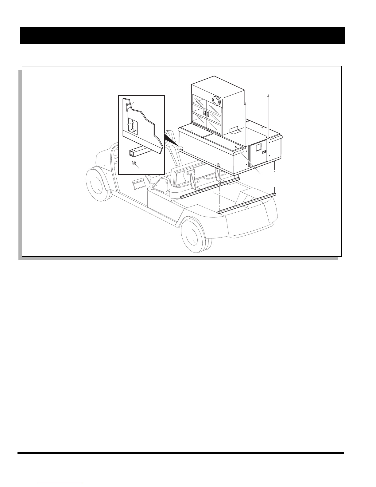
Orient vending unit so that door on unit will be facing the
rear of the vehicle when unit is placed on the mounting
frame (Ref Fig. 1 on page 2). Using a forklift, lift the
refreshment unit and pallet level with the bed of refreshment vehicle. Lift the refreshment unit off of the pallet and
carefully place it onto the mounting frame on vehicle.
Align the four mounting holes on refreshment unit with
corresponding holes on vehicle mounting frame. Secure
unit to frame with four 5/16 - 18 X 1 1/4" bolts (item 1),
eight 5/16" flat washers (item 2) and four 5/16 - 18 lock
nuts (item 3). Tighten hardware firmly.
The vending unit is equipped with two beverage compartments, a cold storage compartment, a consumable ice
compartment, a food display cabinet, two cup dispensers
and a trash bin. Available accessories are listed in illustration (Ref Fig. 1 on page 2).
Tool List Qty. Required
Ratchet, 3/8" drive....................................................... 1
Socket, 1/2", 3/8" drive................................................ 1
Wrench, 1/2" ............................................................... 1
Phillips screwdriver ..................................................... 1
Wrench, 7/16" ............................................................. 1
Drill.............................................................................. 1
Socket adapter, 1/4" drive ........................................... 1
Socket, 5/16", 1/4" drive.............................................. 1
Owner’s Manual and Service Guide
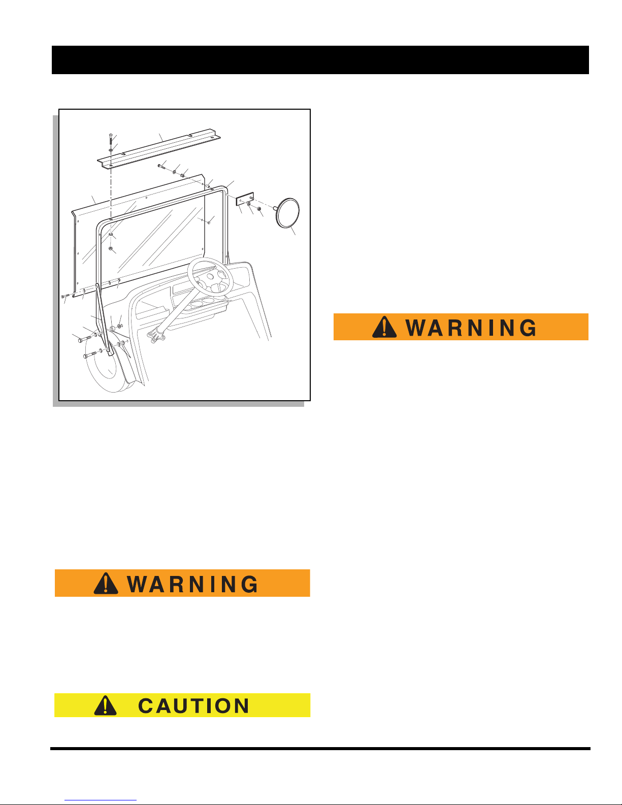
FRONT STRUT INSTALLATION
Position front strut (item 4) and braces (item 5) as shown
(Ref Fig. 2 on page 3) and secure to vehicle at each side
of the cowl with four 5/16 - 18 X 2 1/2" bolts (item 6), four
5/16" lock washers (item 7), two spacers (item 8) and six
3/8" flat washers (item 9). Secure top of braces with two
5/16 - 18 X 2 1/4" bolts (item 10), four 5/16" lock washers
(item 11) and two 5/16 - 18 lock nuts (item 12). Attach
canopy frame mounting plate (item 13) to front strut
using two 1/4 - 20 X 1 1/2" bolts (item 14), four 1/4" flat
washers (item 15) and two 1/4 - 20 lock nuts (item 16) as
shown. Tighten hardware firmly.
WINDSHIELD AND MIRROR INSTALLATION
Typical operation of a Refresher® vehicle on
Page 1
OPERATION AND SERVICE INFORMATION
1
2
Hielo
(sólo este compartimento)
Accesorios de la unidad
para refrescos:
Placas señalizadotas
Bandeja para condimentos
Carro para bebidas
Carro para botellas
Humidor
Montaje para máquinas
de tarjetas de crédito
Caja registradora
Ref Rfi 1
Read all of Manual to become thoroughly familiar with this vehicle. Pay particular attention to all Notes, Cautions and Warnings
a golf course may expose operator to possibility of being struck by a golf ball. Always
operate vehicle with windshield in place.
Insert two bumpers (item 17) and four grommets (item
18) into holes in windshield (item 19) as shown (Ref Fig.
2 on page 3). Position windshield and mirror brackets
(item 20) as shown. Secure windshield and mirror brackets to front strut with four 1/4 - 20 X 1 3/4" bolts (item 21),
four spacers (item 22), four 1/4" washers (item 23) and
four 1/4 - 20 lock nuts (item 24). Tighten hardware firmly.
Thread mirrors (item 25) onto mirror brackets and tighten
securely.
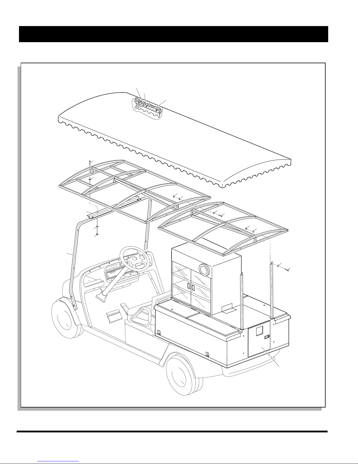
CANOPY FRAME INSTALLATION
Orient the two canopy frame sections end to end aligning
five existing mounting holes as shown (Ref Fig. 3 on
page 4) and fasten together with five 1/4 - 20 X 2" bolts
(item 26), ten 1/4" flat washers (item 27) and five 1/4 - 20
lock nuts (item 28). Orient the assembled canopy frame
as shown and rest front of frame on top mounting plate
and rear of frame on refreshment unit struts. Secure canopy frame to refreshment unit struts with two 1/4 - 20 X 1
Fig. 1 Mounting the Refreshment Unit
1/4" bolts (item 29), four 1/4" flat washers (item 30) and
two 1/4 - 20 lock nuts (item 31) as shown. Secure canopy
frame to front strut with two 1/4 - 20 X 2" bolts (item 32),
four 1/4" flat washers (item 33) and two 1/4 - 20 lock nuts
(item 34) as shown. Tighten hardware firmly.
CANOPY INSTALLATION
Wipe canopy frame with a clean cloth. Unfold canopy
and locate clearance openings in the mounting flap.
Drape canopy over frame and orient canopy on frame so
that clearance openings match strut attachment points
and canopy frame juncture (Ref Fig. 3 on page 4). With
the aid of assistants, pull canopy taut over canopy frame.
Fold mounting flap up inside canopy frame as shown.
Secure each mounting flap to inner surface of canopy
frame with #10 X 1/2" self tapping screws (item 35)
evenly spaced approximately 9" apart as shown. To prevent “gathering” of canopy material during installation,
use the aid of assistants to hold the canopy taut while
securing to canopy frame. For best results, begin securing the canopy at the middle of each side and proceed to
each end of frame.
Page 2
Owner’s Manual and Service Guide
Ref Rfi 2
24
25
18
20
21
18
22
17
19
15
16
9
7
4
8
13
23
14
15
6
5
11
12
10
9
OPERATION AND SERVICE INFORMATION
Read all of Manual to become thoroughly familiar with this vehicle. Pay particular attention to all Notes, Cautions and Warnings
and can be damaged if the unit is removed from pallet and placed directly onto a flat surface. Remove
drain valves from refreshment unit before removing
unit.
Refreshment unit removal is the reverse order of installation. The unit should be lifted onto a pallet being careful
not to damage drains and then handled with a forklift. If a
forklift is not available, be sure an adequate number of
assistants are available to safely lift the vending unit and
pallet.
REFRESHMENT UNIT OPERATION, MAINTENANCE AND CLEANING
Operation
Consumable ice must be stored in the rear
driver side compartment only. Clean this
compartment and the driver side drain valve
before and after each use to reduce the possible contamination of consumable ice.
Fig. 2 Front Strut, Windshield and Mirror Installation
Canned Beverage Compartments - The canned bever-
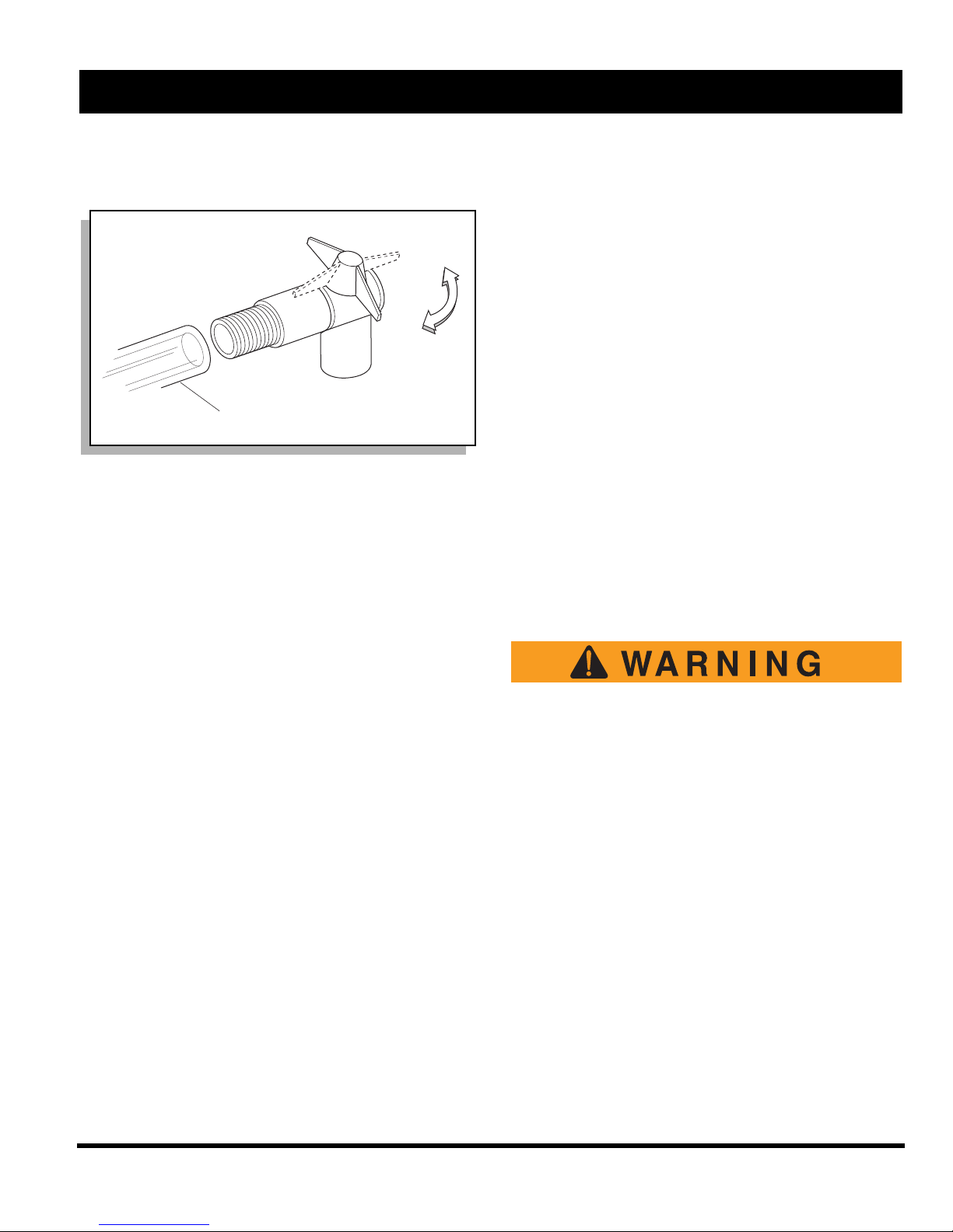
DRAIN VALVE INSTALLATION
Locate the drain hose ends and drain valve mounting
holes under the rear of unit. Orient each drain valve
assembly with spigot facing rearward. Attach each valve
assembly to unit with two 1/4 - 20 X 3/4" screws. Slide
the hose clamps onto the end of each drain hose. Push
the hose ends onto the drain valves and tighten clamps.
REFRESHMENT UNIT REMOVAL
The vending unit is heavy. Care and proper
lifting equipment and procedures must be
used when removing unit to reduce the possibility of severe injury and/or damage to
the unit. Be sure hands and fingers are clear
of unit while lowering.
The drain valves protrude below the frame of the unit
age compartments are designed to carry canned beverages and cooling ice. Cold snacks (sandwiches, fruit,
candy etc.) can also be served from these compartments
by inserting the product into a plastic food container. Precooling the canned beverages will minimize the amount
of ice required to keep the product cool. Maintaining ice
in the canned beverage compartment when the container
is not in service will help to maintain a colder temperature
when the unit is put back into service.
Consumable Ice Compartment - The consumable ice
compartment, located in the rear driver side of the beverage container is to be used for consumable ice only (Ref
Fig. 1 on page 2). This compartment is equipped with it's
own drain per FDA requirements and should not be used
for canned goods or other products.
Trash Compartment - The trash compartment is located
in the rear of the vehicle. The aluminum trash bin should
be lined with a disposable plastic bag to maintain cleanliness. The trash bin is removable from the rear door only.
Drains - The two spigot valves, located under the rear of
the beverage container, drain the compartments. To open
the valves, simply turn the valve handles away from the
vehicle (Ref Fig. 4 on page 5). To close the valves, turn
the valve handles to a position parallel with the vehicle. It
Owner’s Manual and Service Guide
Page 3
OPERATION AND SERVICE INFORMATION
20
21
21
22
22
21
21
20
22
21
21
23
Placa superior
de montaje
Soporte
delantero
Placa de
identificación (dentro
Marco del techo
24
Faldón
de montaje
Ref Rfi 3
Read all of Manual to become thoroughly familiar with this vehicle. Pay particular attention to all Notes, Cautions and Warnings
Page 4
Fig. 3 Canopy Installation
Owner’s Manual and Service Guide
OPERATION AND SERVICE INFORMATION
Sacar el tubo
Cerrado
Abierto
Ref Rfi 4
Read all of Manual to become thoroughly familiar with this vehicle. Pay particular attention to all Notes, Cautions and Warnings
is recommended that the valves be left in an open position while the vehicle is in service.
Fig. 4 Emptying Water from Bins
Cup Dispensers - The cup dispensers are designed to
carry cups ranging from 14 to 20 ounces. To adjust the
cup dispenser for your size and type of cup, remove the
outer collar, insert a sleeve of cups into the dispenser,
and turn the adjusting screw until the cups are securely
held in the cup dispenser. Re-install the outer collar.
Shelves are to be used for any type of dry good such as
chips, peanuts, hats, golf balls etc.
Canopy Cover - Periodically hose off the fabric with
fresh water and allow to dry on the canopy frame.
Maintenance
The door latches and locks will require periodic tightening, adjusting and lubricating with a silicone spray lubricant. We recommend that this be done every two weeks.
Tightening of all screws, nuts and bolts should be accomplished on a regular basis.
REFRESHMENT UNIT REPLACEMENT
PARTS
When ordering refreshment unit replacement parts, reference manufacturer’s I. D. plate located in trash bin compartment.
BEFORE INITIAL USE
Read, understand and follow the safety label on the
instrument panel. Be sure you understand how to operate the vehicle, its equipment and how to use it safely.
Maintaining good performance depends to a large extent
on the operator.
Air Pot - The three one gallon Air Pots are for serving hot
or cold beverages.
Cleaning
Interior Aluminum Surfaces - The interior surfaces
should be cleaned on a daily basis using a soap and
water solution. Thoroughly rinse after cleaning.
Exterior Painted Surfaces - The painted surfaces
should be cleaned on a daily basis using a soap and
water solution.
Exterior Aluminum Surfaces - The aluminum surfaces
should also be cleaned on a daily basis using a soap and
water solution. Periodic cleaning with an aluminum or
stainless steel cleaner is recommended. We recommend
ZEP Stainless Steel Polish or equal.
Drains - The drains should be flushed with a hose on a
daily basis. Periodically, the drains should be cleaned
and sanitized.
Acrylic - The clear acrylic doors should be cleaned daily
with a soap and water solution. Dry with a clean damp
chamois. Do not use window-cleaning sprays.
Polypropylene - The polypropylene doors should be
cleaned daily with a soap and water solution.
Hydrogen gas is generated as a natural part
of the lead acid battery charging process. A
4% concentration of hydrogen gas is explosive and could cause severe injury or death.
Charging must take place in an area that is
adequately ventilated (minimum of 5 air
exchanges per hour).
To reduce the chance of battery explosion
that could result in severe injury or death,
never smoke around or charge batteries in
an area that has open flame or electrical
equipment that could cause an electrical
arc.
Before a new vehicle is put into operation, the items
shown in the INITIAL SERVICE CHART must be performed (Ref Fig. 5 on page 6).
Vehicle battery must be fully charged before initial use.
Check for correct tire inflation. See GENERAL SPECIFI-
CATIONS.
Check for oil or fuel leaks that could have developed in
shipment from the factory.
Owner’s Manual and Service Guide
Page 5
OPERATION AND SERVICE INFORMATION
ARTICULO OPERACION DE SERVICIO
Baterías Cargar la batería
Asientos Quitar la cubierta protectora de plástico
Frenos Comprobar su funcionamiento y ajustar si es necesario
Comprobar el nivel de líquido hidráulico de freno si lo hay
Establecer una distancia de parada aceptable
Neumáticos Comprobar la presión de aire (ver ESPECIFICACIONES)
Combustible Llenar el depósito con combustible adecuado
Motor Comprobar el nivel del aceite
Ref Isc 6
OFFOFF
ONON
FUEL
F
E
Luz indicadora de presión
baja de aceite
Interruptor de llave
de contacto/luces
Indicador de
combustible
Ref Kes 2
Hacia
delante
Marcha
atrás
Ref Dsl 2
Read all of Manual to become thoroughly familiar with this vehicle. Pay particular attention to all Notes, Cautions and Warnings
Determine and record braking distance required to stop
vehicle for future brake performance tests.
Remove the protective clear plastic, that protect the seat
bottom and back rest during shipping, before placing the
vehicle in service.
Fig. 6 Key/Light Switch, Low Oil Pressure Light and
Fuel Gauge
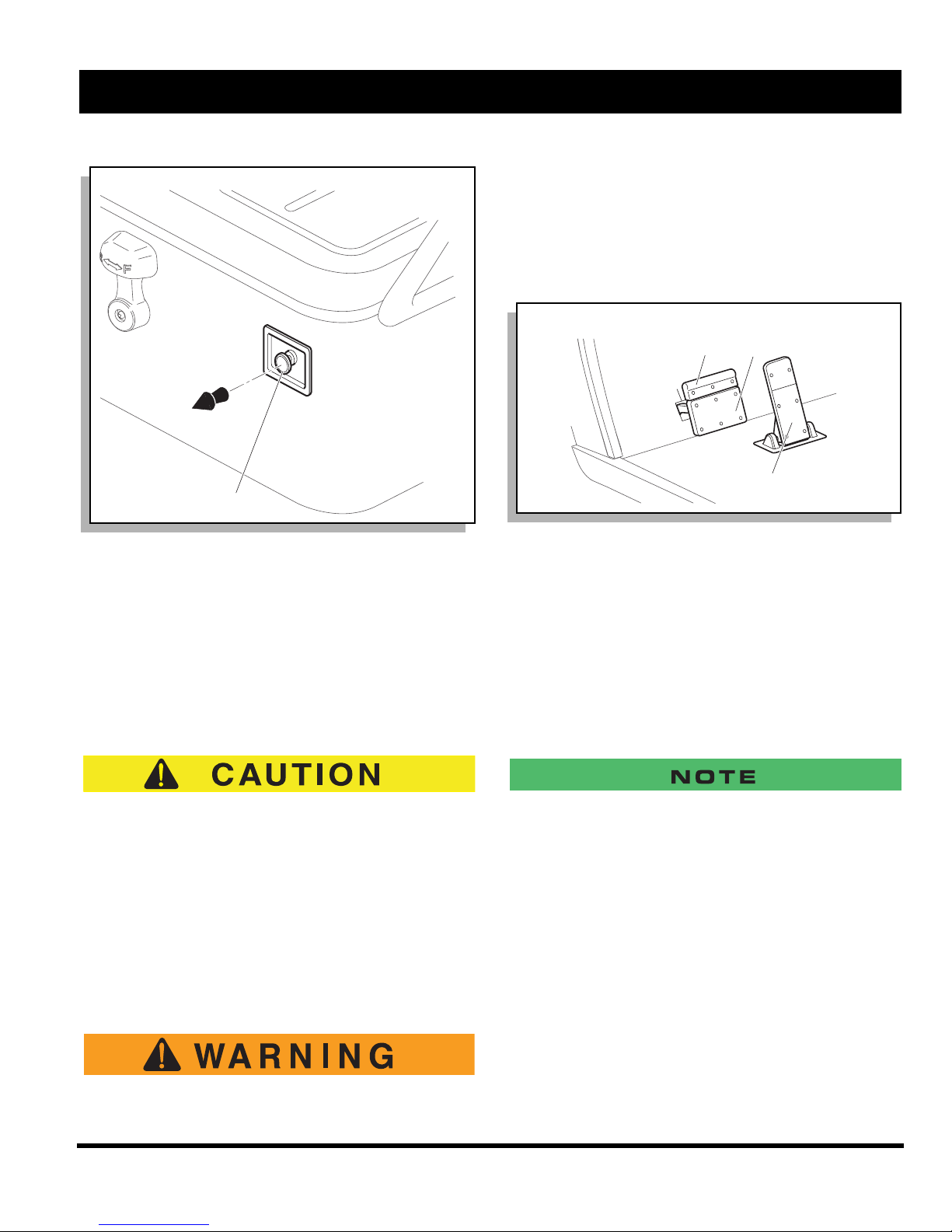
DIRECTION SELECTOR
Fig. 5 Initial Service Chart
CONTROLS AND INDICATORS
Vehicle controls and indicators consist of:
• key/light switch
• direction selector
• choke
• fuel gauge
• low oil pressure indicator light
• accelerator pedal
• combination service and park brake pedal with
front disc brakes (optional)
• horn
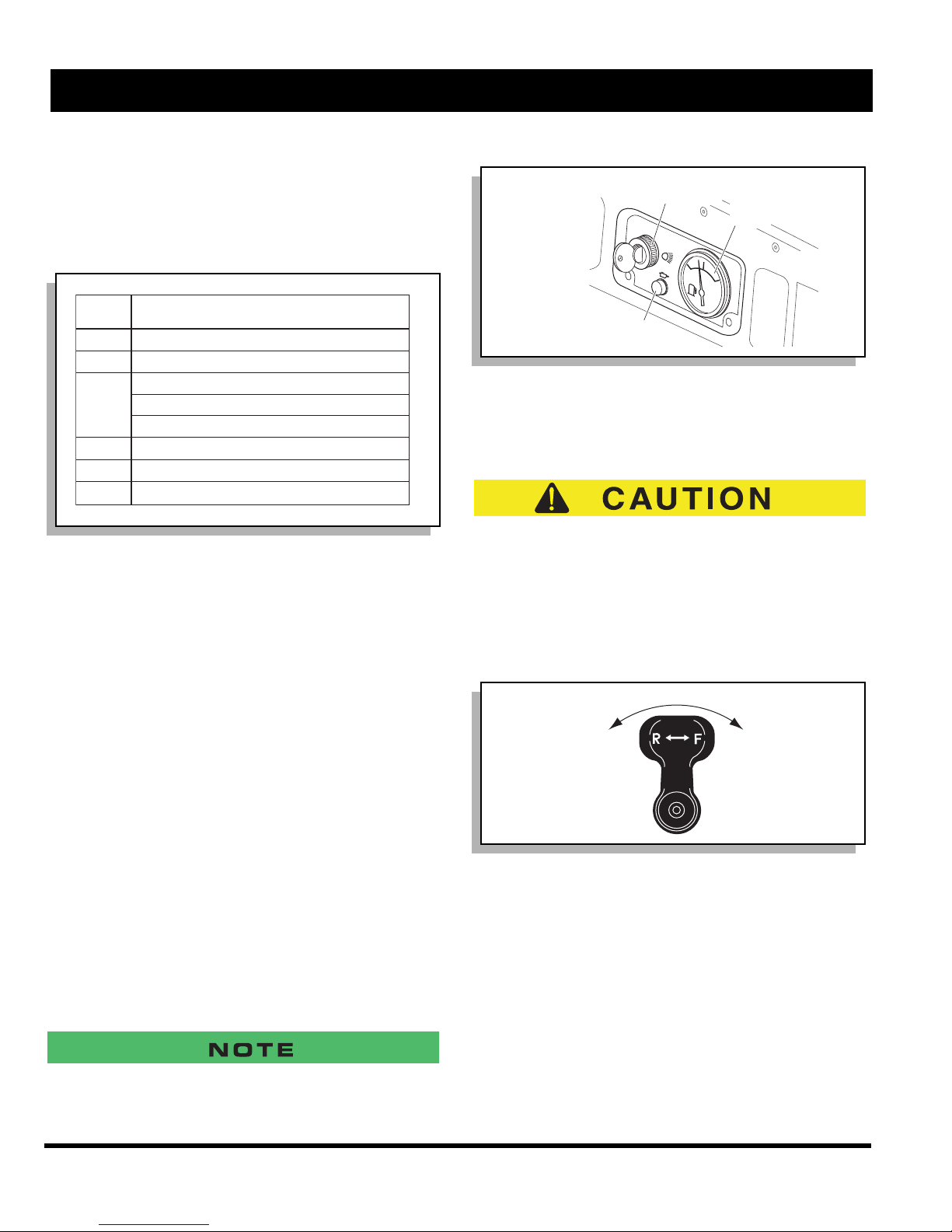
KEY/LIGHT SWITCH
Located on the dash panel, this switch enables the basic
electrical system of the vehicle to be turned on and off by
turning the key. To prevent inadvertent operation of the
vehicle when left unattended, the key should be turned to
the ‘OFF’ position and removed (Ref Fig. 6 on page 6).
If the vehicle is equipped with lights, the key switch has a
position to operate them, indicated by the light icon.
To reduce the possibility of component damage, the
vehicle must be completely stopped before moving
the direction selector.
Located on the seat support panel, this lever permits the
selection of either ‘F’ (forward) or ‘R’ (reverse) (Ref Fig. 7
on page 6). Vehicle should be left in ‘F’ when unattended.
Fig. 7 Direction Selector
CHOKE
The choke is used to aid cold starting (Ref. Fig. 8 on
page 7). See COLD STARTING section for operating
instructions.
If the vehicle is equipped with factory installed custom accessories, some accessories remain operational with the key switch
in the ‘OFF’ position.
Page 6
FUEL GAUGE
The fuel gauge (if equipped) will either be located on the
dash panel (electric) (Ref Fig. 6 on page 6) or directly on
the fuel tank (mechanical).
Owner’s Manual and Service Guide
OPERATION AND SERVICE INFORMATION
Estrangulador
Ref Chk 1
R
Read all of Manual to become thoroughly familiar with this vehicle. Pay particular attention to all Notes, Cautions and Warnings
cause the vehicle to move which could
result in severe injury or death.
With the key switch ‘ON’, depressing the accelerator
pedal starts the engine. When the pedal is released, the
engine will stop (Ref Fig. 9 on page 7). To stop the vehicle more quickly, depress the service brake.
Fig. 8 Choke
LOW OIL PRESSURE INDICATOR LIGHT
A low oil pressure indicator light is located on the dash
panel (Ref Fig. 6 on page 6). The light illuminates when
the oil pressure is low. Check oil level. If oil level is
between ADD and FULL mark on dipstick, a mechanical
problem exists within the engine and the vehicle must
not be driven. Contact a local distributor or authorized
branch.
Freno de
estacionamiento
ef Abc 1
Freno de
servicio
PARK
Acelerador
Fig. 9 Accelerator and Brake Controls
If key switch is ‘ON’ and park brake is set, depressing the
accelerator inadvertently will release the park brake and
will cause the vehicle to move which could cause severe
injury or death.
Depressing the accelerator pedal will release the park
brake if it is engaged. This is a feature to assure the vehicle is not driven with the park brake engaged. Depressing the accelerator pedal is not the preferred method of
releasing the park brake.
To prevent engine damage, do not operate engine
until oil pressure is corrected. Do not overfill engine.
Too much oil may cause smoking or allow oil to
enter the air filter enclosure.
If oil level is below ADD mark on dipstick, add oil to bring
level to FULL mark. Drive vehicle a short distance and
check oil pressure. If oil light does not come on, continue
to use vehicle.
ACCELERATOR PEDAL
Unintentional movement of the accelerator
pedal will release the park brake and may
Depressing the lower section of the brake pedal is the pre-
ferred method of releasing the park brake to assure the longest
service life of brake components.
COMBINATION SERVICE AND PARK BRAKE
PEDAL
The brake pedal incorporates a park brake feature (Ref
Fig. 9 on page 7). To engage, push down on the upper
section of the pedal until it locks in place. The park brake
will release when the service brake pedal is depressed.
Use the lower section of the brake pedal to operate the
service brake system.
OPTIONAL FRONT DISC BRAKES
The front disc brakes activate as the brake pedal
reaches the ‘park’ or ’latch’ position. Depressing the
Owner’s Manual and Service Guide
Page 7
OPERATION AND SERVICE INFORMATION
H
O
R
N
Claxon
PARK
Ref Hor 1
Read all of Manual to become thoroughly familiar with this vehicle. Pay particular attention to all Notes, Cautions and Warnings
brake pedal further will increase the effectiveness of the
front brakes.
HORN
The horn is operated by pushing the horn button located
on the floor to the left of the brake pedal (Ref Fig. 10 on
page 8).
Fig. 10 Horn Button
OPERATING THE VEHICLE
down hill. Use service brake to control
speed when traveling down an incline. A
sudden stop or change of direction may
result in loss of control.
Slow down before and during turns. All
turns should be made at reduced speed.
Never drive vehicle up, down, or across
an incline that exceeds 14° (25% grade).
To reduce the possibility of severe injury or
death resulting from improper vehicle operation, the following warnings must be
observed:
Refer to GENERAL SPECIFICATIONS for
seating capacity.
Depressing accelerator pedal will
release foot operated park brake and
may cause inadvertent vehicle movement. Turn the key to the ‘OFF’ position
whenever the vehicle is parked.
Improper use of the vehicle or the lack of proper
maintenance may result in damage or decreased performance.
Read and understand the following warnings before
attempting to operate the vehicle.
To reduce the possibility of severe injury or
death resulting from loss of vehicle control,
the following warnings must be observed:
When driving vehicle, consider the terrain, traffic conditions and the environmental factors which effect the terrain
and the ability to control the vehicle.
Use extra care and reduced speed when
driving on poor surfaces, such as loose
dirt, wet grass, gravel, etc.
Stay in designated areas and avoid
extremely rough terrain.
Maintain a safe speed when driving
To prevent inadvertent movement when
the vehicle is to be left unattended,
engage the park brake, move direction
selector to forward position, turn key to
‘OFF’ position and remove key.
Make sure that the direction selector is
in correct position before attempting to
start the vehicle.
Always bring the vehicle to a complete
stop before shifting the direction selector.
Do not take vehicle out of ‘gear’ while in
motion (coast).
Check the area behind the vehicle before
operating in reverse.
All occupants must be seated. Keep
entire body inside vehicle and hold on
while vehicle is in motion.
RUN-IN
Check for oil or fuel leaks that could have developed in
shipment from the factory. Avoid full throttle starts and
Page 8
Owner’s Manual and Service Guide
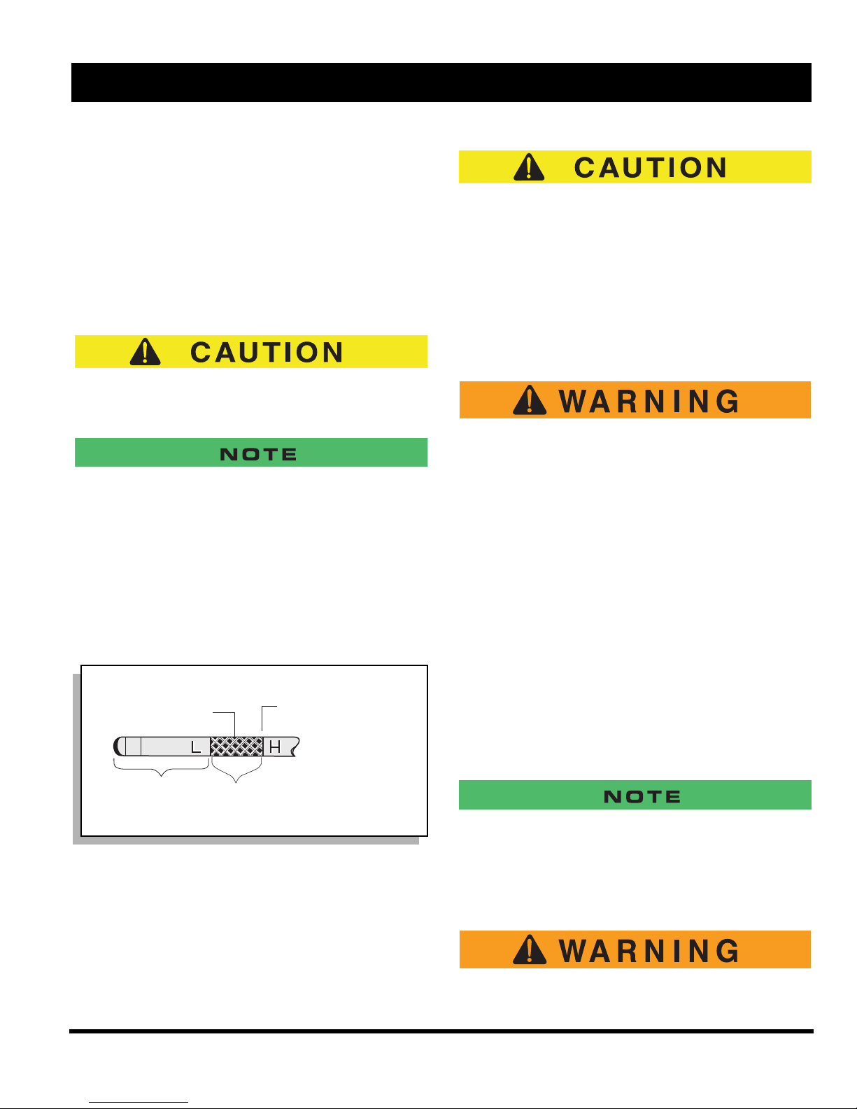
OPERATION AND SERVICE INFORMATION
Nivel máx. de aceite
para motor caliente
No llenar demasiado
Llenar el motor frío
a este punto
Gama
operativa segura
Motor caliente
Añadir aceite
Read all of Manual to become thoroughly familiar with this vehicle. Pay particular attention to all Notes, Cautions and Warnings
rapid acceleration until the engine has achieved operating temperature.
All engines consume more oil than normal during the first
hours of operation. As internal moving parts are run-in,
oil consumption should gradually decrease until the rate
of consumption stabilizes.
Check the oil level per the Periodic Service Schedule.
Add oil if the level on the dipstick indicates that oil is in
the add oil range (Ref Fig. 20 on page 18).
Do not overfill engine. Too much oil may cause
smoking or allow oil to enter the air filter enclosure.
Both the oil dipstick and fill cap must be in place before operating the engine. Failure to install the dipstick and fill cap will
result in oil becoming contaminated and/or being discharged
into the engine compartment.
Oil Dipsticks are unique to this model vehicle. Do not interchange oil dipsticks between models.
The oil should be changed in accordance with the Periodic Service Schedule while the engine is warm. See
SERVICE AND MAINTENANCE for checking oil level
and changing oil procedures.
Do not allow the starter to operate continuously for
more than 10 seconds. Allow 30 seconds between
starting attempts. If the vehicle does not start on the
third attempt, turn the key switch off, set the park
brake and determine the cause of the problem.
If the vehicle had been running and the engine does not
start within 10 seconds, use the choke.
STARTING AND DRIVING
To reduce the possibility of roll-back which
could result in severe injury or vehicle damage, do not release service brake until
engine has started.
To operate vehicle:
• Apply the service brake, place the key in the key
switch and turn it to the ‘ON’ position.
• Move the direction selector to the direction
desired.
• Release the park brake by depressing the service
brake pedal until the park brake releases.
• Slowly depress the accelerator pedal to start the
engine. Release service brake when engine
starts.
• When the accelerator pedal is released, the igni-
tion circuit is de-energized and the engine stops.
To stop the vehicle more quickly, depress the ser-
vice brake pedal.
Fig. 11 Check Oil Level on Dipstick
COLD STARTING
Starting a cold engine may require use of the choke.
Depress the accelerator approximately 1" (2.5 cm) or
until the starter just begins to operate. Pull the choke out
if required. Accelerate slowly and push the choke in completely when the engine runs smoothly.
When the direction selector is in the reverse position, a warning
signal will sound to indicate that the vehicle is ready to run in
reverse.
STARTING THE VEHICLE ON A HILL
To reduce the possibility of roll-back which
could result in severe injury or vehicle dam-
Owner’s Manual and Service Guide
Page 9
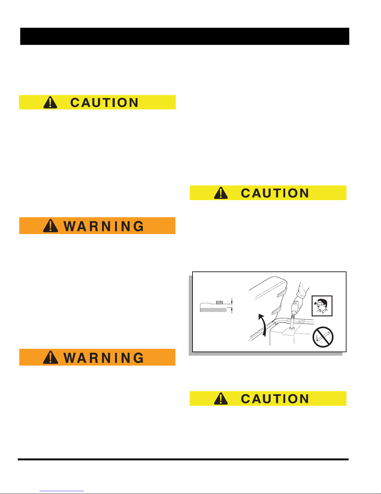
OPERATION AND SERVICE INFORMATION
2,5 cm
Combustible
Ref Ftl 1
Read all of Manual to become thoroughly familiar with this vehicle. Pay particular attention to all Notes, Cautions and Warnings
age, do not release service brake until
engine has started.
Do not hold vehicle on hill by using accelerator and
engine. This will cause premature and excessive
wear to drive train components.
To reduce the possibility of permanent damage to the
drive system, it is important to prevent excessive rollback when starting the vehicle on a hill.
Place left foot on service brake and release the park
brake. Depress accelerator with right foot and release
the service brake by lifting left foot.
COASTING
To reduce the possibility of severe injury or
death from coasting at above recommended
speeds, limit speed with service brake.
On steep hills, it is possible for the vehicle to coast at
greater than normal speeds encountered on a flat surface. To reduce the possible loss of vehicle control and
severe drivetrain damage, speeds should be limited to no
more than the maximum governed speed on level ground
(see GENERAL SPECIFICATIONS). Limit speed by
applying service brake.
Always allow adequate space for the
expansion of gasoline. Leave at least 1"
(2.5 cm) space below bottom of filler
neck.
Inspect fuel cap, tank and other components for leaks or deterioration that
could cause a hazardous condition.
The fuel tank is located under the seat on the passenger
side of the vehicle (Ref Fig. 12 on page 10). Fill the tank
with fresh, clean, automotive grade gasoline (Ref Fig. 39
on page 28). High altitude or heavy use/load applications
may benefit from higher octane gasoline.
Do not use gasoline which contains Methanol.
Some fuels, called oxygenated or reformulated gasoline,
are gasoline blended with alcohols or ethers. Excessive
amounts of these blends can damage the fuel system or
cause performance problems. If any undesirable operating symptoms occur, use gasoline with a lower percentage of alcohol or ether.
Use fresh regular grade unleaded fuel. Ethanol blend
fuels upto 10% are permissable
FUEL
To reduce the possibility of severe injury or
death from improper fuel handling:
Do not smoke near the fuel tank.
Do not refuel near open flame or electri-
cal items which could produce a spark.
Always handle gasoline in a well ventilat-
ed area.
Always wear eye protection to protect
against splashed fuel and fuel vapors.
Page 10
Owner’s Manual and Service Guide
Fig. 12 Fueling
BATTERY
Excessive use of accessories may drain the battery
and leave insufficient reserve to start the vehicle.
The vehicle uses a combination starter/generator to both
start the engine and charge the battery. The engine will
not idle; therefore, the battery cannot be charged while
 Loading...