

E-Z-GO FLEET GOLF CAR, FREEDOM, FREEDOM LE, PDS FREEDOM, PDS FREEDOM SE Owner's Manual And Service Manual
...
OWNER’S MANUAL
R
AND SERVICE GUIDE
28645-G01-GB
ef Fcv 1
ELECTRIC POWERED
FLEET GOLF CARS & PERSONAL VEHICLES
STARTING MODEL YEAR: 2001
REVISED: 10-10-02
SAFETY
For any questions on material contained in this manual, contact an authorized representative for clarification.
Read and understand all labels located on the vehicle. Always replace any damaged or missing labels.
On steep hills it is p ossible for vehi cles to coast at g reater than norm al speeds en countered on a flat surface . To pre-
vent loss of vehicle contr ol and possibl e serious injur y, speeds should be limited to no more than the maxim um speed
on level ground. See GENERAL SPECIFICATIONS. Limit speed by applying the service brake.
Catastrophic damage to the drivetr ain compo nents due to ex cessive speed may result from driving th e vehicle ab ove
specified speed. Da mage caused by excessive speed may cause a loss of ve hicle control, is costly, is considered
abuse and will not be covered under warranty.
Use extra caution when towi ng the v ehicle (s). Do n ot tow a sin gle v ehicle a t speed s in e xcess o f 12 mph (19 kph). D o
not tow more than three vehic les at a time. Do not exceed 5 mph ( 8 kph) while towing multiple v ehicles. Towing the
vehicle at above the rec ommended spee d may result in pe rsonal injury and /or damage to the v ehicle and other property. Vehicles equipped with Prec ision Drive System
located under the passenger seat, in the ‘Tow/Maintenance’ position.
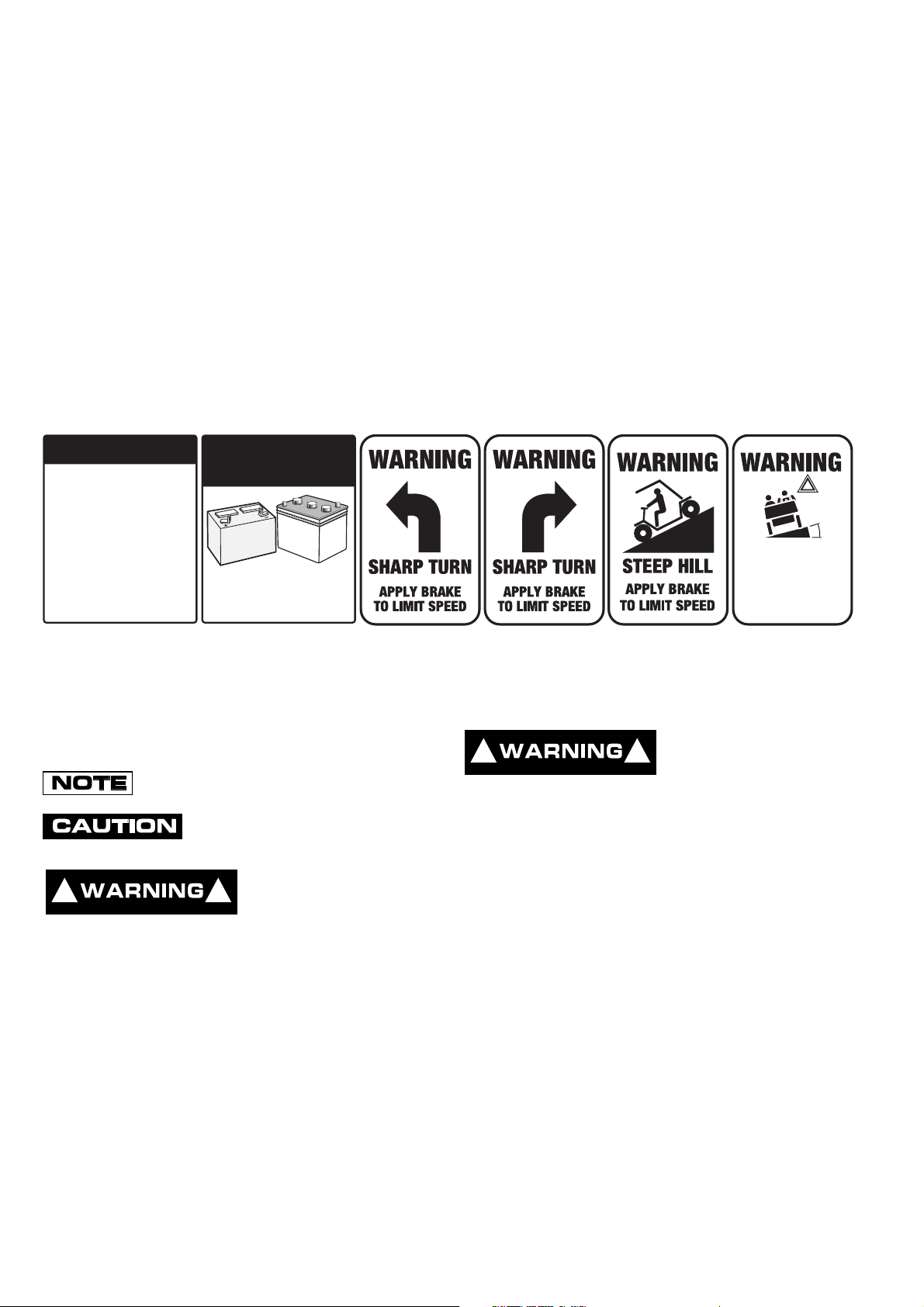
Signs similar to the ones illustrated should be used to warn of situations that could result in an unsafe condition.
™
(PDS) must be towed with the Run-Tow/Maintenance switch ,
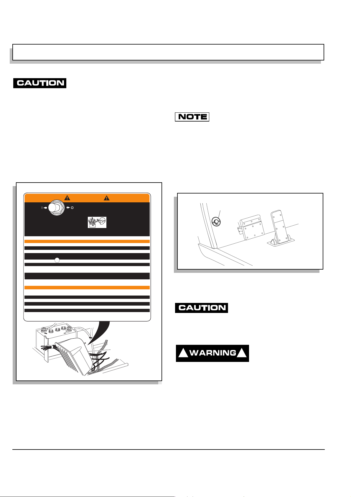
BATTERY WARNING
Battery posts,
terminals and related
accessories contain
lead and lead compounds,
chemicals known
to cause cancer and
reproductive harm.
WASH HANDS
AFTER HANDLING!
BATTERIES
AND RELATED PARTS
CONTAIN LEAD
WASH HANDS
AFTER HANDLING!
WARNING: Battery posts, terminals and related
accessories contain lead and lead compounds,
chemicals known to cause cancer and reproductive harm.
Be sure that this manual remains as part of the permanent service record should the vehicle be sold.
NOTES, CAUTIONS AND WARNINGS
Throughout this g uide NOTE, CAUTION and WARNING
will be used.
A NOTE indicates a condition that should be
observed.
A CAUTION indicates a condition that
may result in damage to the vehicle.
A WARNING indi-
! !
cates a hazardous
condition that could
result in severe injury or death.
! !
lead and lead compounds. Wash hands after
handling.
Battery posts, terminals and related
accessories contain
!
<
14
˚
25
%
DO NOT
DRIVE ACROSS
SLOPES IN
EXCESS OF 14˚
Observe these NOTES, CAUTIONS and WARNINGS;
be aware that servicing a vehicle requires mechanical
skill and a reg ard f or c ond iti on s that could be hazardo us .
Improper service or repair may damage the vehicle or
render it uns af e.
(NOTES, CAUTIONS AND WARNINGS CONTINUED ON INSIDE OF BACK COVER)

OWNER’S MANUAL AND
SERVICE GUIDE
ELECTRIC POWERED
FLEET GOLF CARS &
PERSONAL VEHICLES
FLEET GOLF CAR
FLEET PDS GOLF CAR
FREEDOM
™
FREEDOM™ SE
™
FREEDOM
PDS FREEDOM
LE
™
PDS FREEDOM™ SE
™
™
LE
2+2
PDS FREEDOM
SHUTTLE
E-Z-GO Division of Textron reserves the right to make design changes without obligation to make these changes on units previously sold and the information
contained in this manual is subjec t to change without notice.
E-Z-GO Division of Text ron is no t liable f or erro rs in this man ual or f or incide nt al o r c onse quentia l da mage s th at resul t fro m t he use of the materia l in this manual.
CUSTOMER SERVICE DEPARTMENT IN USA PHONE: 1-800-241-5855 FAX: 1-800-448-8124
OUTSIDE USA PHONE: 010-1-706-798-4311 FAX: 010-1-706-771-4609
E-Z-GO DIVISION OF TEXTRON, INC., P.O.BOX 388, AUGUSTA, GEORGIA USA 30903-0388
Owner’s Manual and Service Guide
Page i

GENERAL INFORMATION
This vehicle has been designed and manufactured in the United States of America (USA) as
a ‘World Vehicle’. The Standards and Specifications listed in the following text originate in
the USA unless otherwise indicated.
The use of non Original Equipment Manufacturer (OEM) approved parts may void the
warranty.
Overfilling batteries may void the warranty.
BATTERY PROLONGED STORAGE
All batteries will self discharge over time. The rate of self disc harge varies depending on the
ambient temperature and the age and condition of the batteries.
A fully charged battery will not freeze in winter temperatures unless the temperature falls
below -75° F (-60° C).
For winter storage, the batteries must be clean, fully charged and disconnected from any
source of electrical drain. The battery charger and the controller are both sources of
electrical drain. Unplug the battery charger DC plug from the vehicle receptacle.
On PDS vehicles, disconnect the controller from the battery set by selecting the ‘TOW/
MAINTENANCE’ position on the RUN-TOW/MAINTENANCE SWITCH located under the
passenger seat.
As with all electric vehicle s, the batte ries must be ch ecked and recharged as required or at a
minimum of 30 day intervals.
Page ii
Owner’s Manual and Service Guide

TABLE OF CONTENTS
SAFETY ................................................................................................................. Inside covers
GENERAL INFORMATION ........................................................................................................ ii
SAFETY INFORMATION...... ....... ...... ....... ...... ...... ....... ...... ....... ...... ....... ...... ....... ...... ....... ...........v
BEFORE INITIAL USE .............................................................................................................. 1
Fig. 1 Initial Service Chart ......................................................................................................................1
PORTABLE CHARGER INSTALLATION ............................................................................................................1
Fig. 2 Proper Charger Installation ..........................................................................................................2
Fig. 3 Charger Receptacle Location ......................................................................................................2
CONTROLS AND INDICATORS ...............................................................................................2
KEY/LIGHT SWITCH ....................................... ............. ............. ......................... ............ .....................................2
Fig. 4 Key/Light Switch & State of Charge Meter ..................................................................................2
DIRECTION SELECTOR .....................................................................................................................................3
Fig. 5 Direction Selector Types ..............................................................................................................3
STATE OF CHARGE METER ....................... ............. ............. ............ ......................... ............. ..........................3
ACCELERATOR PEDAL ....................... ............. ............ ............. ......................... ............. ..................................3
Fig. 6 Accelerator and Brake Controls ...................................................................................................3
COMBINATION BRAKE AND PARK BRAKE PEDAL .......... ............. ............. ............ ............. ............ ............. ...3
RUN - TOW/MAINTENANCE SWITCH (PDS VEHICLES ONLY) .......................................................................3
Fig. 7 Run-Tow/Maintenance Switch ..................................................................................................... 4
HORN ..................................................................................................................................................................4
Fig. 8 Horn Button .................................................................................................................................. 4
OPERATING THE VEHICLE ..................................................................................................... 4
PRECISION DRIVE SYSTEM™ .......................................................................................................................... 5
Performance Options..................................................................................................................................... 5
Fig. 9 Performance Options ...................................................................................................................5
Regenerative Braking.....................................................................................................................................6
Pedal-Up Brakng............................................................................................................................................ 6
Walk-Away Feature........................................................................................................................................6
Anti-Roll Back Feature................. ............ ............. ............. ......................... ............ .......................................6
Anti-Stall Feature ........................................................................................................................................... 6
High Pedal Disable Feature .................................................................................... .. ....... .... .. .. ......................6
Diagnostic Mode Feature................................................................... ......... .... .... .... ......... .... ..........................7
STARTING AND DRIVING ................................... ......................... ............ ............. .............................................7
STARTING VEHICLE ON A HILL (Non PDS Vehicl e ) ........................... ......................... ............. ............. ........... 7
COASTING ..........................................................................................................................................................7
LABELS AND PICTOGRAMS ............. ............ ............. ............. ............ ............. ............ .....................................7
SUN TOP AND WINDSHIELD .............................................................................................................................8
VEHICLE CLEANING AND CARE ............................................................................................8
VEHICLE CLEANING ........................ ......................... ............. ......................... ............ .......................................8
VEHICLE CARE PRODUCTS ..................... ......................... ............. ............. ......................... ............................8
REPAIR ................................ .......................................................... ............................................ 9
LIFTING THE VEHICLE ......................................................................................................................................9
Fig. 10 Lifting the Vehicle ......................................................................................................................9
WHEELS AND TIRES .........................................................................................................................................9
Tire Repair .................................................................. .. .. ..... .. .. .. .. .. .. .. .. ..... .. .. .. .. .. .. .. .. .....................................9
Wheel Installation....................................................................... .... .. .... ....... .... .. .... .. ......... ............................10
Fig. 11 Wheel Installati o n ..................... ......................... ............ ............. ............. ................................10
LIGHT BULB REPLACEMENT ..........................................................................................................................10
Fig. 12 Headlight, Turn Signal & Marker Light Bulb Replacement ...................................... .. ......... .. .. .11
Fig. 13 Tail and Brake Light Bulb Replacement .................................................... ............ ..................11
TRANSPORTING VEHICLE ....................................................................................................11
TOWING ............................................................................................................................................................11
HAULING ........................................................................................................................................................... 12
Owner’s Manual and Service Guide
Page iii

TABLE OF CONTENTS
SERVICE AND MAINTENANCE ..............................................................................................12
SERIAL NUMBER PLATE LOCATION ............................................................................................................. 12
Early Production ..........................................................................................................................................12
Fig. 14 Serial Number Plate Location - Early Production .................................................................... 13
Late Production .............................................................................................. ....... .. .... .. .............................. 13
Fig. 15 Serial Number Plate Location - Late Production ..................................................................... 13
PERIODIC SERVICE SCHEDULE .................................................................................................................. 14
Fig. 16 Periodic Service Schedule ...................................................................................................... 14
TIRE INSPECTION ..................... ............. ............ ......................... ............. ............. ............ .............................. 15
BRAKES ........................................................................................................................................................... 15
Periodic Brake Test for Mechanical Brakes................................................................................................. 15
Fig. 17 Typical Brake Performance Test ............................................................................................. 16
REAR AXLE ...................................................................................................................................................... 16
Fig. 18 Add, Check and Drain Axle Lubricant - Early Production ........................................................ 16
Fig. 19 Add, Check and Drain Axle Lubricant - Late Production ......................................................... 16
Checking the Lubricant Level .............................................................................. .. .... .. .... .. .. ..... ................... 17
LUBRICATION ..................................................................................................................................................17
Fig. 20 Lubrication Points - Early Production ...................................................................................... 17
Fig. 21 Lubrication Points - Late Production ....................................................................................... 17
PDS SYSTEM TEST .........................................................................................................................................17
HARDWARE .....................................................................................................................................................17
Fig. 22 Torque Specifications and Bolt Grades ...................................................................................18
CAPACITIES AND REPLACEMENT PARTS ....................... ............. ............ ............. ............ ............. .............18
Fig. 23 Capacities and Replacement Parts .........................................................................................18
BATTERIES AND CHARGING ................................................................................................19
SAFETY ............................................................................................................................................................ 19
BATTERY ......................................................................................................................................................... 19
BATTERY MAINTENANCE ..............................................................................................................................19
At Each Charging Cycle .............................................................................................................................. 19
Monthly........................................................................................................................................................20
Electrolyte Level and Wa te r.......................... ............. ............ ............. ............ ............. ................................ 20
Fig. 24 Correct Electrolyte Level ......................................................................................................... 20
Fig. 25 Water Purity Table ..................................................................................................................20
Fig. 26 Automatic Watering Gun ......................................................................................................... 21
Battery Cleaning..........................................................................................................................................21
Fig. 27 Preparing Acid Neutralizing Solution .......................................................................... .. .... ....... 21
Battery Replacement................................................................................................................................... 21
Fig. 28 Battery Connections ................................................................................................................ 22
Prolonged Storage........................................................... .. .. .. .. .. ....... .. .. .. .. .. .. .. ....... .. .. .. .. .. .. ..........................22
Fig. 29 Freezing Point of Electrolyte ...................................................................................................23
BATTERY CHARGING .....................................................................................................................................22
AC Voltage ............. ......................... ............. ............. ............ ............. ............ ............................................. 23
TROUBLESHOOTING ......................................................................................................................................23
Hydrometer..................................................................................................................................................23
Fig. 30 Hydrometer ............................................................................................................................. 24
Using A Hydrometer.................................................................................................................................... 24
BATTERY CHARGER MAINTENANCE ........................................................................................................... 24
Fig. 31 Hydrometer Temperature Correction .................... ............. ......................... ......................... ...25
Fig. 32 Cleaning Auxiliary Contact in Charger Plug ....................................................................... .....25
GENERAL SPECIFICATIONS..................................................................................................27
TXT ELECTRIC - FLEET...................................................................................................................................28
TXT PDS ELECTRIC - FLEET........................ ............ ............. ............. ............ ............. ............ ........................ 29
TXT ELECTRIC - FREEDOM™......................................................................................................................... 30
TXT ELECTRIC - FREEDOM™ SE................................................................................................................... 31
TXT ELECTRIC - FREEDOM™ LE ................................................................................................................... 32
TXT PDS ELECTRIC - FREEDOM™.................................. ............ ............. ............. ............ ............. ............... 33
TXT PDS ELECTRIC - FREEDOM™ SE.... ............ ............. ............ ............. .................................... ................. 34
TXT PDS ELECTRIC - FREEDOM™ LE............................................ ............ ............. ............ ............. ............. 35
TXT ELECTRIC - SHUTTLE 2+2....................................................................................................................... 36
Page iv
Owner’s Manual and Service Guide

TABLE OF CONTENTS
Fig. 29 Vehicle Dimensions............. ............. ............ .......................... ............ ............. ............ .............. 37
Fig. 30 Vehicle Dimensions, Incline Specifications and Turning Clearance Diameter ..........................38
Fig. 31 PowerWise™ Portable Battery Charger Dimensions.............................................. ..................39
LIMITED WARRANTIES........................................................................................................... 41
DOMESTIC WARRANTY...................................................................................................................................42
INTERNATIONAL WARRANTY (2001)........................................ ......................... ............. ............ ....................43
INTERNATIONAL WARRANTY (2002)........................................ ......................... ............. ............ ....................44
INTERNATIONAL WARRANTY (2003)........................................ ......................... ............. ............ ....................45
DECLARATION OF CONFORMITY (EUROPE ONLY)............................................................ 47
FLEET GOLF CAR (2000)..................................................................................................................................48
FREEDOM™ GOLF CAR (2000) .......................................................................................................................49
FREEDOM™ HP GOLF CAR (2000) ....................................................... .. ....... .. .... .. .. .... ..... .... .. .. .... .. .. ..............50
SHUTTLE 2+2 (2000).........................................................................................................................................51
FLEET AND FREEDOM™ GOLF CAR (2002)...................................................................................................52
SHUTTLE 2+2 (2002).........................................................................................................................................53
LABELS AND PICTOGRAMS.................................................................................. Appendix A
Owner’s Manual and Service Guide
Page v

N
TABLE OF CONTENTS
otes:
Page vi
Owner’s Manual and Service Guide

SAFETY INFORMATION
This manual has been designe d to assist in maintaining t he vehicle in accordanc e with procedur es developed by the
manufacturer. Adherence to these procedures an d troubleshoo ting tips will en sure the be st possible service from the
product. To reduce the chance of personal injury or property damage, the following must be carefully observed:
GENERAL
Many vehicles are used for a variety of tasks beyond the original intended use of the vehicle; therefore, it is impossible
to anticipate and warn aga ins t e ve ry po ss ib le c om bi nati on o f c ircu ms tances tha t may occur. No warnings can take the
place of good common sense and prudent driving practices.
Good common sense an d prudent driving practices do more to prevent accidents and i njury than all of the warnin gs
and instructions combined. The manufactur er strongly suggests that al l users and maintenance personnel read this
entire manual paying particular attention to the CAUTIONS and WARNINGS contained therein.
If you have any questions regarding this vehicle, contact your closest representative or write to the address on the back
cover of this publication, Attention: Product Service Department.
TEXTRON Golf, Turf & Specialty Products reserves the right to make design changes without obligation to make these
changes on units previously sold and the information contained in this manual is subject to change without notice.
TEXTRON Golf, Turf & Specialty Products is not lia ble for err or s in th is ma nual or for i ncide ntal or cons equ ent ial dam ages that result from the use of the material in this manual.
This vehicle conforms to the current applicable standard(s) for safety and performance requirements.
These vehicles are desi gne d and ma nufactured for off-road use. They do not con form to F ede ra l Mo tor Vehicle Safety
Standards of the United States of America (USA) and are not equ ipped fo r operati on on pu blic str eets. Som e comm unities may permit these vehi cles to be operated on their streets on a limit ed basis and in accordance wi th local ordinances.
With electric powe red vehicles, be sure that al l electrical accessories ar e grounded directly to the batte ry (-) post.
Never use the chassis or body as a ground connection.
Refer to GENERAL SPECIFICATIONS for vehicle seating capacity.
Never modify the vehicle in any way that will alte r the weight distributi on of the vehicle, decreas e its stability
or increase the speed beyond the factory specification. Such modifications can cause serious personal injury
or death. Modifications that increase the speed and/or weight of the vehicle will extend the stopping distance and may
reduce the stabilit y of the vehicle. Do not make a ny such modification s or changes. The manufac turer prohibits and
disclaims responsibility for any such modifications or any other alteration which would adversely affect the safety of the
vehicle.
Vehicles that are capable of higher sp eeds must limit th eir speed to no more th an the speed of other ve hicles when
used in a golf course en vironment. Additi onally, speed should be further moderated by the environmental condition s,
terrain and common sense.
GENERAL OPERATI O N
Always:
• Use the vehicle in a responsible manner and maintain the vehicle in safe operating condition.
• Read and observe all warnings and operation instruction labels affixed to the vehicle.
• Follow all safety rules established in the area where the vehicle is being operated.
Owner’s Manual and Service Guide
Page vii

SAFETY INFORMATION
• Reduce speed to compensate for poor terrain or conditions.
• Apply service brake to control speed on steep grades.
• Maintain adequate distance between vehicles.
• Reduce speed in wet areas.
• Use extreme caution when approaching sharp or blind turns.
• Use extreme caution when driving over loose terrain.
• Use extreme caution in areas where pedestrians are present.
MAINTENANCE
Always:
• Maintain the vehicle in accordance with the manufacturer’s periodic service schedule.
• Ensure that repairs are performed by those that are trained and qualified to do so.
• Follow the manufac tu re r’s maintenance p roce dur es fo r t he v eh icle . B e s ur e to disable the vehicle b efore per for ming
any maintenance. Disabling includes removing the key from the key switch and removal of a battery wire.
• Insulate any tools used within the battery area in order to prevent sparks or battery explosion caused by shorting the
battery terminals or associated wiring. Remove the batteries or cover exposed terminals with an insulating material.
• Check the polarity of each battery terminal and be sure to rewire the batteries correctly.
• Use specified replacement parts. Never use replacement parts of lesser quality.
• Use recommended tools.
• Determine that to ols and procedures not specif ically recommended by the man ufacturer will not compromise the
safety of personnel nor jeopardize the safe operation of the vehicle.
• Support the vehi cle using wheel cho cks and jack stands. Never g et under a vehicle t hat is s upported by a jack. Lift
the vehicle in accordance with the manufacturer’s instructions.
• Maintain the vehicle in an area away from exposed flame or persons who are smoking.
• Be aware that a vehicle that is not performing as designed is a potential hazard and must not be operated.
• Test drive the vehicle after any repairs or maintenance. All tests must be conducted in a safe area that is free of both
vehicular and pedestrian traffic.
• Replace damaged or missing warning, caution or information labels.
• Keep complete records of the maintenance history of the vehicle.
The manufacturer cannot anticipate all situations , therefore people attem pting to maintain or repair the vehi cle must
have the skill an d expe rience to rec ogniz e and protect t hem selv es from potenti al si tuation s that could res ult in seve re
personal injury or death and damage to th e vehicle. Use extrem e caution and, if un sure as to the potenti al for injury,
refer the repair or maintenance to a qualified mechanic.
Page viii
Owner’s Manual and Service Guide

SAFETY INFORMATION
VENTILATION
Hydrogen gas is generated in the charging cycle of batteries and is explosive in concentrations as low as 4%. Because
hydrogen gas is lighter than air, it will collect in the ceiling of buildings necessitating proper ventilation. Five air
exchanges per hour is considered the minimum requirement.
Never charge a vehicl e in an area that is sub ject to flame or spark. Pay particul ar attention to natur al gas or propane
water heaters and furnaces.
Always use a dedicated circuit for each battery charger. Do not permit other appliances to be plugged into the receptacle when the charger is in operation.
Chargers must be installe d and operated in accorda nce with charger manufact urers recommendations or app licable
electrical code (whichever is higher).
Owner’s Manual and Service Guide
Page ix

Notes:
SAFETY INFORMATION
Page x
Owner’s Manual and Service Guide

SAFETY INFORMATION
Read all of manual to become thoroughly familiar with this vehicle. Pay particular attention to all Notes, Cautions and Warnings
GENERAL
The following text is prov ide d as r eco mm end ed b y part II
of ASME/ANSI B56.8-1988. E-Z-GO strongly endorses
the contents of this specification.
PART II
FOR THE USER
4 GENERAL SAFETY PRACTICES
4.1 Introduction
4.1.1 Like other ma ch in es, carriers can c aus e in jur y
if improperly used or main tained. Part II contains broad
safety practices applicable to carrier operati ons. Before
operation, the user shall establish such additional specific safety practices as may reasonably be required for
safe operation.
4.2 Stability
4.2.1 Experience has shown that this vehicle, which
complies with this standard, is stable when properly
operated and when operated in acco rdance with speci fic
safety rules and practices established to meet actual
operating terrain and conditions. However, improper
operation, faulty maintenance, or poor housekeeping
may contribute to a co nditio n of instabili ty and defe at th e
purpose of the standard. Som e of the conditions which
may affect stability are failure of the user to follo w safety
practices; also, ground and floor conditions, grade,
speed, loading, the op er ation o f the car rie r wi th i mprop er
loads, battery weight, dy namic and static forces, and the
judgement exercised by the carrier operator.
(a) The user shall train carrier operators to adhere
strictly to the operating instructions stated in this Standard.
(b) The user shall survey specific operating conditions
and environment, and establ ish and train carrier operators to comply with additional, specific safety practices.
4.3 Nameplates, Markings, Capacity, and Modifica-
tions
4.3.1 The user shal l maintain in a legible con dition
all nameplates, warnings, and instructions which are
supplied by the manufacturer.
4.3.2 The user shall no t p erf orm any m odi fic ation or
addition which affects capacity or safe operation, or
make any change not in accordance with the owner’s
manual without the manufact urer’s prior written authorization. Where authorized modifications have been made,
the user shall ensure that capacity, operation, warning,
and maintenance in struction plates, tags, or decals ar e
changed accordingly.
4.3.3 As required under paras. 4.3.1 or 4.3.2, the
manufacturer shall be contacted to secure new nameplates, warnings, or instructions which shall then be
affixed in their proper place on the carrier.
4.4 Fuel Handling and Storage
4.4.1 The user shall supervise the stor age an d h an-
dling of liquid f uels (when us ed) to be ce rtain that it is in
accordance with ap propriate paragraphs of ANSI/NFPA
505 and ANSI/NFPA 30.
4.4.2 Storage and handling of liquefied petroleum
gas fuels shall be in acc ordance with appropriate paragraphs of ANSI/NFPA 505 and ANSI/NFPA 58. If such
storage or handling is not i n com pliance with these standards, the user shall pr event the car rier from bei ng used
until such storage and handling is in compliance with
these standards.
4.5 Changing and Charging Storage Batteries for
Electric Personnel and Burden Carriers
4.5.1 The user shall require battery changing and
charging facilities and procedures to be in accordance
with appropriate paragraphs of ANSI/NFPA 505.
4.5.2 The user shall periodically inspect facilities
and review procedures to be certain that appropriate
paragraphs of ANSI/NFPA 505, are strictly complied with,
and shall familiarize carrier operators with it.
4.6 Hazardous Locations
4.6.1 The user shall determine the hazard classifi-
cation of the particul ar atmosphere or location in whi ch
the carrier is to be used i n accordance with ANSI/NFPA
505.
4.6.2 The user shall permit in haz ardous are as o nly
those carriers approved and of the type required by
ANSI/NFPA 505.
4.7 Lighting for Operating Areas
4.7.1 The user, in accordance with his responsib ility
to survey the environment and operating conditions, shall
determine if the carrier requires lights and, if so, shall
equip the carrier with appropriate lights in accordance
with the manufacturer’s recommendations.
Owner’s Manual and Service Guide
Page xi

SAFETY INFORMATION
Read all of manual to become thoroughly familiar with this vehicle. Pay particular attention to all Notes, Cautions and Warnings
4.8 Control of Noxious Gases and Fumes
4.8.1 When equipment powered by internal com-
bustion engines is used in enclosed areas, the atmosphere shall be maintained within limits specified in the
American Conference of Governmental Industrial
Hygienists publication, “Threshold Limit Values for
Chemical Substances and Phys ical Agents in the Workroom Environment”. Thi s sh all be ac com pl is hed by ven tilation provided b y the user, and/or the installati on, use,
and proper maintenance of em ission control equipment
recommended or provided by the manufacturer of the
equipment.
4.9 Warning Device(s)
4.9.1 The user shall make periodic inspections of
the carrier to be certain that the sound-produ cing and/or
visual device(s) are mai ntained in good operatin g condition.
4.9.2 The user shall determine if operating conditions require the carrier to be equipped with additional
sound-producing a nd/or visual dev ices and be re sponsible for providing and mai ntaining such dev ices, in ac cordance with the manufacturer’s recommendations.
5 OPERATING SAFETY RULES AND
PRACTICES
5.1 Personnel and Burden Carrier Operator
Qualifications
5.1.1 Only persons who are trained in the proper
operation of the carrier shall be authorized to operate the
carrier. Operators shall be qualified as to visual, auditory,
physical, and m ental ability to safely o perate the equipment according to Section 5 and all other applicable
parts of this Standard.
5.2 Personnel and Burden Carrier Operators’
Training
5.2.1 The user shall conduct an operators’ training
program.
5.2.2 Successful completi on of the operators’ training program shall be r equired by the user befor e operation of the carrier. The program shall be presented in its
entirety to all new operators and not condensed for those
claiming previous experience.
5.2.3 The user should include in the operators’ training program the following:
(a) instructional material provided by the manufac-
turer;
(b) emphasis on safety of passeng ers, mater ial l oads,
carrier operator, and other employees;
(c) general safety rules co ntained w ithin th is Standard
and the additional s pecific rules determined by the user
in accordance with this Standard, and why they were fo r mulated;
(d) introduction of equipment, control locations and
functions, and explana tion of how they work when used
properly and when used i mproperly, and surface conditions, grade, and other co nditions of the environment in
which the carrier is to be operated;
(e) operational performance tests and evaluations during, and at completion of, the program.
5.3 Personnel and Burden Carrier Operator
Responsibility
5.3.1 Operators shall abide by the following safety
rules and practices in paras. 5.4, 5.5, 5.6, and 5.7.
5.4 General
5.4.1 Sa feguard th e ped estrian s at all ti mes. Do not
drive carrier in a manner that would endanger anyone.
5.4.2 Riding on the carrier by persons other than the
operator is authorized only on personnel seat(s) provided
by the manufacturer. All parts of the body shall remain
within the plan view outline of the carrier.
5.4.3 Wh en a carrier is to be left unattended, stop
carrier, apply the parking brake, st op the engine or turn
off power, turn off the control or ignition circuit, and
remove the key i f provided. Block the wheels if mac hine
is on an incline.
5.4.4 A carrier is considered unattended when the
operator is 25 ft. (7.6 m) or more fr om the carrier which
remains in his vie w, or whenever the oper ator le aves the
carrier and it is not within his view. When the operator is
dismounted and within 25 ft. (7.6 m) of the c arrier still in
his view, he still must have contr ols neutralized, and the
parking brake(s) set to prevent movement.
5.4.5 Maintain a safe distance from the edge of
ramps and platforms.
5.4.6 Us e only approved carriers in ha za rd ous lo ca tions, as defined in the appropriate safety standards.
5.4.7 Report all accidents involving personnel,
building structures, and equipment.
5.4.8 Oper ators shall not add to, or m odify, the carrier.
Page xii
Owner’s Manual and Service Guide

SAFETY INFORMATION
Read all of manual to become thoroughly familiar with this vehicle. Pay particular attention to all Notes, Cautions and Warnings
5.4.9 Carriers shall not be parked or left unatte nded
such that they block or obstruct fire aisles, access to
stairways, or fire equipment.
5.5 Traveling
5.5.1 Observe all traffic regulations, including autho-
rized speed limits. Under nor mal traffic conditions keep
to the right. Maintain a safe distance , based on sp eed of
travel, from a carrier or v ehicle ahead; and k eep th e carrier under control at all times.
5.5.2 Yield the right of way to pedestrians, ambulances, fire tru cks, or other carrier s or vehicles in e mergency situations.
5.5.3 Do not pass another carrier or vehicle traveling in the same d irection at in tersections, bli nd spots, or
at other dangerous locations.
5.5.4 Keep a clear view of the path of travel,
observe other tra ffic and personn el, and ma intain a saf e
clearance.
5.5.5 Slow down or stop, as conditio ns dictate, and
activate the sound-producing warning device at cross
aisles and when visibility is obstructed at other locations.
5.5.6 Ascend or descend grade s slo wly.
5.5.7 Avoid turning, if possible, and use extreme
caution on grades, ramps, or inclines; normally travel
straight up and down.
5.5.8 Under all travel conditions the c arrier shall b e
operated at a speed that wil l permit it to be brou ght to a
stop in a safe manner.
5.5.9 Make starts, stops, turns, or direction reversals in a smooth manner so as not to shift the load,
endanger passengers, or overturn the carrier.
5.5.10 Do not indulge in dangerous activities, such as
stunt driving or horseplay.
5.5.11 Slow down when approaching, or on, wet or
slippery surfaces.
5.5.12 Do not drive carrier onto any elevator unless
specifically authorized to do so. Approach elevators
slowly, and then enter squarely after the elevator car is
properly leveled. Once on the elevator, neutralize the
controls, shut off power, and set parking brakes. It is
advisable that all other personnel leave the elevator
before a carrier is allowed to enter or exit.
5.5.13 Avoid running over loose objects, potholes,
and bumps.
5.5.14 To negotiate turns, reduce speed to improve
stability, then turn hand steering wheel or tiller in a
smooth, sweeping motion.
5.6 Loading
5.6.1 Handle only stable and safely arrang ed loads.
When handling off-center loads which cannot be centered, operate with extra caution.
5.6.2 Handle only loads within the capacity of the
carrier as specified on the nameplate.
5.6.3 Handle loads exceedin g the dimensions used
to establish carrier capacity with extra caution. Stability
and maneuverability may be adversely affected.
5.7 Operator Care of Personnel and Burden
Carriers
5.7.1 At the beginning of each shift during which the
carrier will be used, th e operator shall check the c arrier
condition and inspect the tires, warning devices, lights,
battery(s), speed and di rection al controll ers, brakes , and
steering mechanis m. If the carrier i s found to be in need
of repair, or in any way unsafe, the matter shall be
reported immediately to the design ated auth ority and the
carrier shall not be operated unti l it has been restor ed to
safe operating condition.
5.7.2 If during operation the carrier becomes unsafe
in any way, the matter shall be repor ted immediately to
the designated authority, and the carrier shall not be
operated until it has been restored to safe operating condition.
5.7.3 Do not make repairs or adjustments unless
specifically authorized to do so.
5.7.4 The engine shall be stopp ed and the operator
shall leave the carrier while refueling.
5.7.5 Spillage of oil or fuel shall be carefully and
completely absorbed or evaporated and fuel tank cap
replaced before starting engine.
5.7.6 Do not operate a c arrier wi th a l eak in the fuel
system or battery(s).
5.7.7 Do not use open flam es for checking electrolyte level in storage battery(s) or liquid level in fuel tanks.
6 MAINTENANCE PRACTICES
6.1 Introduction
6.1.1 Carriers may become hazardous if mainte-
nance is neglected. Therefore, maintenance facilities,
trained personnel, and procedures shall be provided.
Such facilities may be on or off the premises.
Owner’s Manual and Service Guide
Page xiii

SAFETY INFORMATION
Read all of manual to become thoroughly familiar with this vehicle. Pay particular attention to all Notes, Cautions and Warnings
6.2 Maintenance Procedures
6.2.1 Maintenance and inspection of all carriers
shall be performed in conformance with the manufacturer’s recommendations and the following practices.
(a) A scheduled pr eventive maintenance, lub rication,
and inspection system shall be followed.
(b) Only qualifie d and authorized personnel shall be
permitted to maintain, repair, adjust, and inspect carriers.
(c) Before under taking maintenance o r repair, follow
the manufacturer’s recommendations for immobilizing
the carrier.
(d) Block chassis before working underneath it.
(e) Before disco nnecting any part of the engine fuel
system of a gasol in e o r dies el powered carrier with g ra vity feed fuel systems, be sure shutoff valve is closed, and
run engine until fuel system is depleted and engine stops
running.
(f) Before disconnecting any part of the engine fuel
system of LP gas powered carriers, close the LP gas cylinder valve and run th e engine until fu el in the syste m is
depleted and the engine stops running.
(g) Operation to check performance of the carrier shall
be conducted in an authorized area where safe clearance exists.
(h) Before commen cing operation of the carr ie r, follow
the manufacturer’s instructions and recommended procedures.
(i) Avoid fire hazards and have fir e protection equipment present in the work area. Do not use an open flame
to check level o r leakage of fuel, battery electro lyte, or
coolant. Do not use open pans of fuel or flammable
cleaning fluids for cleaning parts.
(j) Properly ventilate the work area.
(k) Handle LP gas cylinders with care. Physical damage, such as dents, scrapes, or gouges, may dangerously weaken the tank and make it unsafe for use.
(l) Brakes, steering mechanisms, speed and directional control mecha nisms, warning devices, ligh ts, governors, guards, and safety devices shall be inspected
regularly and maintained in a safe operating condition.
(m) Special carriers or devices designed and
approved for hazardous area operation shall be
inspected to ensure that maintenance preserves the original approved safe operating features.
(n) Fuel systems shall be checked for leaks and condition of parts. If a leak is found, action shall be taken to
prevent the use of the carrier until the leak has been
eliminated.
(o) The carrier manufacturer’s capacity, operation, and
maintenance instruc tion plates, tags, or decals shall be
maintained in legible con dit ion .
(p) Batteries, motors, speed and directional controllers, limit switch es, protec tive dev ices, ele ctrical cond uctors, and connections shall be inspected and main tained
in conformance with manufacturers recommended procedures.
(q) Carriers shall be kept in a clean conditi on to minimize fire hazards and facilitate detection of loose or
defective parts.
(r) Modifications and additions which affect capacity
and safe machine operation shall not be performed by
the customer or user without ma nufact urer’s prior written
authorization; wher e auth orized modifi cati ons have been
made, the user shall ensure that capacity, operation,
warning, and maintenance instruction plates, tags, or
decals are changed accordingly.
(s) Care shall be taken to ensure t hat all repl acement
parts are interchangeable with the or igina l parts and of a
quality at least equal to that provided in the original
equipment.
END OF ASME/ANSI B56.8-1988 TEXT
Page xiv
Owner’s Manual and Service Guide

SAFETY INFORMATION
Read all of manual to become thoroughly familiar with this vehicle. Pay particular attention to all Notes, Cautions and Warnings
GENERAL
The following text is prov ide d as r eco mm end ed b y part II
of ANSI / NGCMA Z130.1 - 1993. E-Z-G O, as a memb er
of the National Golf Car Manufacturers Association
(NGCMA), strongly endor ses the conten ts of this specification.
PART II
MAINTENANCE AND OPERATIONS
5. GENERAL SAFETY PRACTICES
5.1. Introduction
Like other machines, golf cars can cause injury if improperly used or maintained. This section contains broad
safety practices recommended for safe golf car operations. Before operation, the controlling party should
establish such additional specific safety practices as may
be reasonably required for safe operations.
Experience has shown th at golf cars which comply wit h
the provisions stated i n Part II of this Standard are safe
when properly operated in accordance with the safety
and operation warnings affixed to every golf car. The safe
operation is enhanced w hen the golf cars are operated
within a specific set of operation instructions, safety rules
and practices established to meet actual operating terrain and conditions.
The safety informatio n contained in P art II is intend ed to
provide the controlling party with basic safety information
and to encourage the controlling party to implement a
golf car safety program.
It is suggested and recommended that Part II be
reprinted in the golf car manufacturer’s operation and
service manuals to enc ourage safe opera tions and pr actices at the controlling party’s facility.
5.2.1. Steep Grade
In areas where steep grades exist, golf car operations
should be restricted to the design ated golf car pathways
where possible, and shall be identified with a suitable
warning giving the followin g infor mation : “Warning, steep
grade, descend slowly with one foot on brake.”
5.2.2. Wet Areas
Wet grassy areas ma y cause a golf car to lose traction
and may affect stability. Wet areas shall be chained or
roped off to prevent golf car operations or be identified by
a suitable warning not to ope rate golf cars in this area
due to wet terrain.
5.2.3. Sharp Turns, Blind Corners, Bridge
Approaches
Sharp turns, blind spots, bridge approaches and other
potentially hazardous areas shall be either chained or
roped off to prevent golf car ope rations or identified wit h
a suitable warning to the operator of the nature of the
hazard and stating the proper prec autions t o be taken to
avoid the hazard.
5.2.4. Loose Terrain
Loose terrain ma y cause a golf car to lose traction and
may affect stability. Areas of loose terrain should be
repaired if possible, or chained or roped off to prevent
golf car operation or identified by a suitable warning to
operators not to operate golf cars in this area due to
loose terrain or possible hazardous conditions.
5.2.5. Golf Car/Pedestrian Interfer en ce Area s
5.2. Safety Survey
The controlling party shall perform a safety s urvey periodically, and as conditions warrant to the ir premises, to
identify areas where golf cars should not be operated
and to identify possible hazards.
Owner’s Manual and Service Guide
Areas where pe destrians an d golf car s interfere shall be
avoided whenever poss ible by rer outing the golf car tr affic or the pedestrian traffic to eliminate the interference. If
elimination of th e interf erence is not p ossible o r is high ly
impractical, signs shall be erected warning pedestrians
of the golf car tra ffic and golf c ar oper ators of t he p edestrian traffic and to drive slowly and use extreme caution.
Page xv

SAFETY INFORMATION
Read all of manual to become thoroughly familiar with this vehicle. Pay particular attention to all Notes, Cautions and Warnings
6. MAINTENANCE
6.1. Introduction
6.1.1. Golf cars may become haz ardou s if mai ntenance
is neglected or impr operly performed. T herefore maintenance facilities, trained personnel and procedures in
accordance with the manufacturer’s recommendations
should be provided by the controlling party.
6.2. Preventive Maintenance
A regularly sched uled inspe ction and prev entive mai ntenance program in accordance with the manufacturer’s
recommendations should be established. Such a program will be a valuable tool in providing the golfing
patron with a safe, properly operating golf car and
thereby help to avoid accidents.
6.2.1. Personnel
Only qualified, t rained a nd authoriz ed pers onnel shall be
permitted to inspect, adjust and maintain golf cars.
liters per car per charge. Because of the highly v olatile
nature of hydrogen gas and its propensity to rise and
accumulate at the ceiling in pocke ts, a minimum of 5 air
changes per hour is rec omm end ed. The controllin g part y
shall consult applicable fire and safety codes for the specific ventilation levels required as well as the use of
explosion proof electrical apparatus.
6.2.4. Maintenance Procedures
All maintenance sha ll be performed in accordance with
the manufacturer’s recommended maintenance procedures as outlined in the manufacturer’s operation and
service manuals.
6.2.5. Maintenance Safety Procedures
All maintenance sha ll be performed in accordance with
the manufacturer ’s recommended safety procedur es as
outlined in the manufacturer’s operation and service
manuals. The followin g list of recommended safety pro cedures are general in nature an d in no way supersede
the manufacturer’s specific instructions.
6.2.2. Parts and Materials
Only manufacturer’s recommended replacement parts
and materials shall be used.
6.2.3. Ventilation
Maintenance and st orage areas shall be properly ven tilated to avoid fire haza rds in accor dance with applic able
fire codes and ordinances.
6.2.3.1. Ventilation for gasoline powe red golf cars shall
be provided to remove flammable vapors, fumes and
other flammable mat erials. Consu lt applica ble fire code s
for specific levels of ventilation.
6.2.3.2. Ventilation for electric powered golf cars shall
be provided to remove the accumulation of flammable
hydrogen gas emitted dur ing the charging process. The
amount of hydrogen gas emitted depends upon a number of factors such as the c ondition of the batteries, t he
output rate of the battery ch arger an d the am oun t of tim e
the batteries are on charge. Hydrogen emissions are
generally considered to be in the area of 10 to 20 cubic
6.2.5.1. Follow manufacturer’s instructions for immobilizing golf car before beginning any maintenance.
6.2.5.2. Block chassis before working underneath golf
car.
6.2.5.3. Before disconnecting any part of the fuel system, drain the syste m and turn all shut off valves to the
‘OFF’ position to prevent leakage or accumulation of
flammable fuels in the work area.
6.2.5.4. Avoid fire hazards and have fire protection
equipment available.
6.2.5.5. Before performing any maintenance on an electric golf car, disable the elect rical system in accordance
with the manufacturer’s instructions.
6.2.5.6. Use only properly insulated tool s when working
on electrically powered golf cars or around batteries.
6.2.5.7. Brakes, steering mechanisms, warning devices,
Page xvi
Owner’s Manual and Service Guide

SAFETY INFORMATION
Read all of manual to become thoroughly familiar with this vehicle. Pay particular attention to all Notes, Cautions and Warnings
governors and all other safety devices shall be inspected
and maintained in a safe and proper oper ating condi tion
and shall not be modified as supplied by the manufacturer.
6.2.5.8. After each maintenance or repair the golf car
shall be driven by qualified, trained an d authorized personnel to ensure proper operation and adjustment.
6.2.5.9. Driving golf car to check for proper operation
and adjustment after repair shall be performed in an area
that is free of vehicular and pedestrian traffic.
6.2.5.10. Record all main tenance perfo rmed in a ma intenance record log by date, name of person performing
maintenance and typ e of maintenance. Controlling party
management should periodically inspect maintenance
log to ensure currency and completeness of entries.
7. FUELS HANDLING AND STORAGE/
BATTERY CHARGING
7.1. The con trolling party shall supervise th e storage
and handling of liquid fuels in accordance with applicable
fire and safety requirements.
7.2. Storage an d handling of liquefied petroleum gas
fuels shall be in accordance with American Gas Association recommenda tions and applicab le fire safety requirements.
7.3. The contr olling party shall require bat tery changing and charging fac ilit ies an d pr ocedures to be in accordance with applicable ordinances or regulations (also
see paragraph 6.2.3.2).
7.4. The controlling party shall periodically inspect
facilities and review procedures to be certain that the
procedures in parag raphs 6.2.3.2 and 7.3 are being followed.
6.2.5.11. Provide operator comment cards to assist in
identifying non-periodic maintenance needs for specific
golf cars.
6.2.6. The controlling party shall maintain in a legible
condition all nameplates, warnings and instructions
which are supplied by the manufact urer.
6.2.7. The controlling party shall not perform any modification or addition whic h affects capacity or safe operation, or make any change not in accordance with the
owner’s manual without the manufacturer’s prior written
authorization. Where authorized modifications have been
made, the controlling party shall ensure that capacity,
operation, warning and maintenance instruction plates,
tags or decals are changed accordingly.
6.2.8. As required under paragraphs 6.2.6 and 6.2.7 the
manufacturer shall be contacted to secure new nameplates, warnings or instructions which shall then be
affixed in their proper place on the golf car.
8. OPERATING SAFETY RULES AND
PRACTICES
8.1. Operator Qualifications
8.1.1. Only authorized persons shall be allowed to oper-
ate golf cars. It is recommended that no persons be
allowed to operate golf car s except those persons who
posses a valid motor vehicle driver’s license.
8.1.2. The controlling party shall display the operation
and safety instructio ns as recommended by the golf car
manufacturers and the golf cour se safety r ules in a c onspicuous place near the golf ca r rental area or golf car
pick-up area. It is also recommended, as with all motor
vehicles, that the warning “Do not operate golf cars when
under the influence o f alcohol or drugs.” be pos ted in a
conspicuous location.
Owner’s Manual and Service Guide
Page xvii

N
SAFETY INFORMATION
Read all of manual to become thoroughly familiar with this vehicle. Pay particular attention to all Notes, Cautions and Warnings
otes:
Page xviii
Owner’s Manual and Service Guide
OPERATION AND SERVICE INFORMATION
Read all of manual to become thoroughly familiar with this vehicle. Pay particular attention to all Notes, Cautions and Warnings
Thank you for purchasin g this vehicle. B efore drivi ng the
vehicle, we ask you to spend some time reading this
Owner’s Manual and Servi ce Guide . This guid e contains
the information that will assist you in maintaining this
highly reliable vehicle. Some illustrations may show
items that are optional for your vehicle. This guide covers
the operation of sev eral vehicles; therefo re, some pictorial views may not represent your vehicle. Physical differences in controls will be illustrated.
This vehicle has bee n designed and manufactured as a
‘World Vehicle’. Some countries have in dividual requirements to comply with their specifications; therefore,
some sections may not apply in your country.
Most of the service procedures in this guide can be
accomplished using common automotive hand tools.
Contact your service representative on servicing the
vehicle in accor dance with the Periodic Servi ce Schedule.
Service Parts Manu als and Technician’s Repair and Service Manuals are available from a local Distributor, an
authorized Branch or the Service Parts Department.
When ordering parts or requesting information for your
vehicle, provide ve hicl e model, seri al numbe r and man ufacture date code.
BEFORE INITIAL USE
Read, understand and follow the safety label on the
instrument panel. Be sure you understand how to oper ate the vehicle, its equip ment and how to use it safely.
Maintaining good perfor man ce dep end s t o a lar ge ex ten t
on the operator.
Hydrogen gas is generat-
! !
ing process. A 4% concentration of hydrogen gas is
explosive and could cause severe injury or death.
Charging must take place in an area that is adequately ventilated (minimum of 5 air exchanges per hour).
To reduce the chance of battery explosion
that could result in severe injury or death,
never smoke around or charge batteries in
an area that has open flam e or electrical
equipment that could cause an electrical
arc.
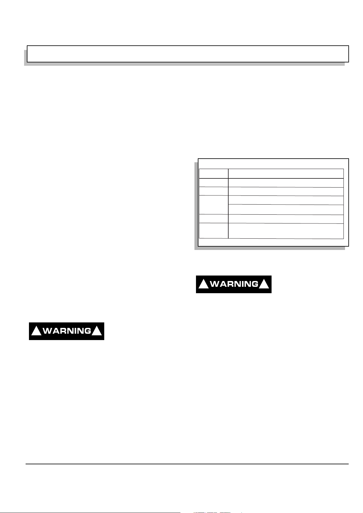
Before a new vehicle is put into operation, the items
shown in the INITIAL SERVICE CHART must be performed (Ref Fig. 1 on page 1).
ed as a natural part of the
lead acid battery charg-
Vehicle batteries must be fully charged before initial use.
Check for correct tire inflation. See GENERA L SPECIFI-
CATIONS.
Determine and record braki ng distance required to stop
vehicle for future brake performance tests.
Remove the protective c lear pla stic, tha t prote ct the seat
bottom and back rest during s hipping, bef ore placing the
vehicle in service.
ITEM SERVICE OPERATION
Batteries Charge batteries
Seats Remove protective plastic covering
Brakes Check operation and adjust if necessary
Establish acceptable stopping distance
Tires Check air pressure (see SPECIFICATIONS)
Portable Remove from vehicle and properly mount
Charger
Ref Isc 1
Fig. 1 Initial Service Chart
PORTABLE CHARGER INSTALLATION
To prevent overheat-
! !
ing that may cause
serious damage to
the charger and create the potential for fire,
do not block or obstruct the airways. Por t able chargers must be mounted on a platform above the ground or in such a manner
as to permit the maximum air flow underneath and around the charger.
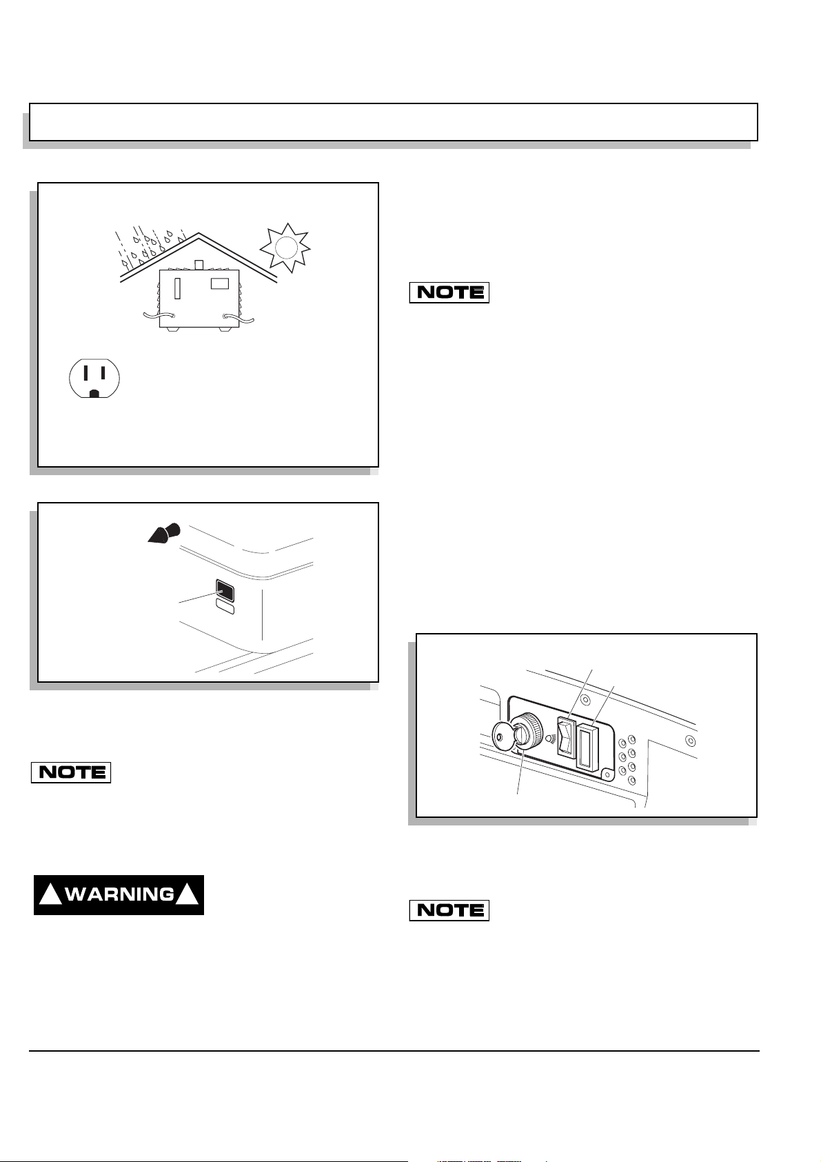
Portable chargers a re shipped with the vehicle. P rior to
vehicle or charger ope ration, char gers must be remo ved
and mounted on a platform or wall above the ground to
permit maximum air flow around and underneath the
charger. If the charger is operated in an outdoor location,
rain and sun protection mu st be provided (Ref Fig. 2 on
page 2). A dedicated circuit is required for the charge r.
Refer to the charger ma nual for appropriate circuit protection. The charger may remain plugged in to the AC
outlet. To charge the vehicle, refer to the instruction
labels on the char ger. Insert the polarized DC plug completely into the vehicle receptacle (Ref Fig. 3 on page 2).
The charger will automat ically start a few seconds after
plug insertion. The ch arger will automatically st op when
Owner’s Manual and Service Guide
Page 1
OPERATION AND SERVICE INFORMATION
R
Read all of manual to become thoroughly familiar with this vehicle. Pay particular attention to all Notes, Cautions and Warnings
The charging (DC) cord is equipped with a polarized con-
Provide Protection From Elements
nector which fits into a matching rece ptacle on the vehi cle.
The power (AC) cord is equipped with a groun ded plug.
Do not attempt to remove, cut or bend the ground post.
the charge r.
If vehicle is to be charged with a non E-Z-GO
charger, refer to the instructions supplied with
Do Not Block Louvered Airways
NEMA 15 - 5R Grounded AC Receptacle
110 - 120 VAC. Dedicated 15 AMP Circuit
Locations outside the US and Canada: Reference
appropriate local electrical code and charger manufacturer recommendations for AC power requirements
Ref Pci 1
Fig. 2 Proper Charger Installation
Front of
Vehicle
Charger
Receptacle
Ref Crl 1
Fig. 3 Charger Receptacle Location
batteries are fully charged and the DC plug can be
removed to permit use of the vehicle.
CONTROLS AND INDICATORS
Vehicle controls and indicators consist of:
• key/light switch
• direction select or
• state of charge meter
• accelerator pedal
• combination service and park brake pedal
• run - tow/maintenance switch (PDS only)
• horn
KEY/LIGHT SWITCH
Located on the d as h panel , thi s switc h e nables the basic
electrical system of the vehicle to be turned on and off by
turning the key. To prevent inadvertent operation of the
vehicle when left unattended, the key should be turned to
the ‘OFF’ position and removed (Ref Fig. 4 on page 2).
Direction Selector (PDS only)
State of Charge Meter
OFF
ON
Looping the DC cord through the steering
wheel when charging, serves as a good
reminder to store the cord out of the way when finished with
charging. The DC plug can be damaged by driving over or
catching the cord on the vehicle when driving away. A charging
interlock feature on the PowerWise™ charger prevents vehicle
operation while the DC plug is inserted in vehicle receptacle.
To prevent a physical
! !
hazard that could result
in an electrical shock or
electrocution, be sure that the charger plug is not
damaged and is inserted into a grounded receptacle.
The power (AC) cord is equipped with a
grounded plug, do not attempt to pull out,
cut or bend the ground post.
Page 2
Owner’s Manual and Service Guide
Key/Light Switch
ef Kes 1
Fig. 4 Key/Light Switch & State of Charge Meter
If the vehicle is equipped with lights, the key switch has a
position to operate them, indica ted by the light ic on.
If the vehicle is equipped with factory installed
custom accessories, some accessories remain
operational with the key switch in the ‘OFF’ position.
OPERATION AND SERVICE INFORMATION
R
R
Read all of manual to become thoroughly familiar with this vehicle. Pay particular attention to all Notes, Cautions and Warnings
DIRECTION SELECTOR
To prevent loss of
! !
tion selector while the vehicle is in motion.
Moving the selector will result in a sudden
slowing of the vehicle and the beeping of a
warning device.
control, do not move
PDS vehicle direc-
Park
Brake
PARK
Service
Brake
To reduce the possibility of component
damage, the vehicle must be complete-
ly stopped before moving the direction selector.
On PDS models, if the direction selector is shifted before the
vehicle comes to a complete stop, a warning beeper will activate.
Located on the seat support panel or the dash panel, this
lever or switch permits the selection of either ‘F’ (forward), ‘R’ (reverse) or neutral (the posit ion between forward and reverse). Vehicle should be left in neutral when
unattended (Ref Fig. 5 on page 3).
ef Dsl 1
FWD
REV
FWD
REV
Forward
Reverse
Neutral, as shown
Fig. 5 Direction Selector T ypes
Reverse
Neutral
Forward
STATE OF CHARGE METER
Located in the dash, the state of charge m eter indicates
the amount of usable power in the batter ies (Ref Fig. 4
on page 2).
ACCELERATOR PEDAL
Unintentional move-
! !
ment of the acceler-
ator pedal will
release the park brake and may cause the
vehicle to move which could result in
severe injury or death.
With the key switch ‘ON’, depressing the accelerator
pedal starts the motor. When the pedal is released, th e
motor will stop (Ref Fig. 6 on page 3). To stop the vehicle
more quickly, depress the service brake.
ef Abc 1
Fig. 6 Accelerator and Brake Controls
If key switch is ‘ON’ and park brake is set, depressing the
accelerator inadver tently will releas e the park brake an d
will cause the vehicle to move whic h could c ause sev ere
injury or death.
Depressing the accelerator pedal will release the park
brake if it is engaged. This is a feature to assure the vehicle is not driven with the park brake engag ed. Depressing the accelerat or pedal is not the preferred method of
releasing the park brake.
Depressing the lower section of the brake
pedal is the preferred method of releasing the
park brake to assure the longest service life of brake components.
Accelerator
COMBINATION BRAKE AND PARK BRAKE
PEDAL
The brake pedal incorpo rates a park brake feature (Ref
Fig. 6 on page 3). To engage, push down on the upper
section of the pedal until it locks in place. The park brake
will release when the service brak e pedal is depressed.
Use the lower section of the brake pedal to operat e the
service brake system.
RUN - TOW/MAINTENANCE SWITCH
(PDS VEHICLES ONLY)
To reduce the possi-
! !
bilty of severe inju-
ry or death resulting
from loss of vehicle control, consider the
grade of the terrain the vehicle is on and set
vehicle’s park brake accordingly before
switching the Run - Tow/Maintenance
switch to the ‘Tow/Maintenance’ position.
When in the ‘Tow/Maintenance’ position, the
Anti-Roll Back and Walk-Away safe ty features of the PDS system no longer function.
Owner’s Manual and Service Guide
Page 3
OPERATION AND SERVICE INFORMATION
Read all of manual to become thoroughly familiar with this vehicle. Pay particular attention to all Notes, Cautions and Warnings
Before attempting to tow vehicle, move
the Run-Tow/Maintenance switch to the
‘Tow/Maintenance’ position. Failure to do so will damage the
controller or motor.
Before disconnecting or connecting a battery, or any other wiring, move the Run-Tow/Maintenance switch to the ‘Tow/Maintenance’ position.
After connecting a battery, or any other wiring, wait a minimum
of 30 seconds before moving the Run-Tow/Maintenance switch
to the ‘Run’ position.
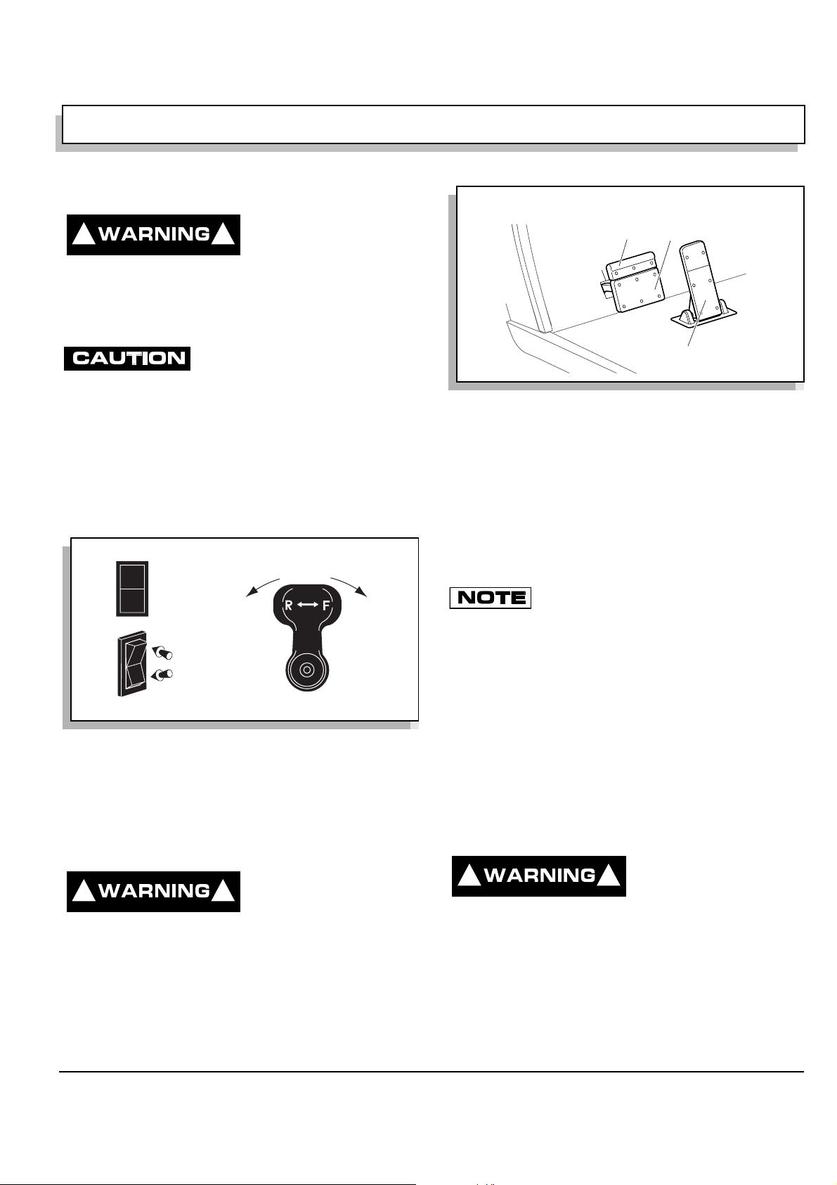
The PDS vehicl e is equipped with a two position sw itch
located under the pass en ger s i de o f th e s ea t on th e c ontroller environmental cover (Ref Fig. 7 on page 4).
WARNING
■ Tampering with or unauthorized modification of this unit
73093-G01
RUN
TOWING
Always select 'TOW/MAINTENANCE'
position before towing
■ To disable electrical system, place switch in 'TOW/ MAINTENANCE' position and remove battery wire
■ After reconnecting batteries, allow a minimum of 30 seconds before selecting 'RUN' position
THE FOLLOWING CODES REQUIRE THAT THE REAR WHEELS BE RAISED BEFORE PERFORMING TESTS
Beep Fault Symptoms Correction Required
1-1 Controller Failure Vehicle will not run Check motor wiring & motor Ω. Replace controller
1-2 Throttle fault Solenoid clicks, will not run Replace/adjust pedal box, harness
1-4 High pedal disable Vehicle will not run Release pedal/check pedal box, linkage & switch
2-4 Solenoid coil failure Vehicle will not run Check coil connections/wiring,
or disconnected replace solenoid if required
3-1 Solenoid driver fail Vehicle will not run Check coil wiring for shorts, replace controller
3-3 Solenoid did not close Vehicle will not run Check all solenoid wiring, replace solenoid if required
3-4 Field winding open Solenoid clicks, will not run Check motor & controller field connections,
replace power harness or motor if required
4-1 Armature open Solenoid clicks, will not run Check motor & controller armature connections,
replace power harness or motor if required
4-3 Solenoid drop out Vehicle stops Check solenoid/wiring, replace if required
THE FOLLOWING CODES REQUIRE THAT THE VEHICLE BE OPERATED UNDER LOAD WHILE PERFORMING TESTS
Beep Fault Symptoms Correction Required
1-3 Speed sensor fault Vehicle runs slowly Check speed sensor connections & magnet/torque,
replace speed sensor if required
2-1 Low battery voltage Vehicle performance reduced Charge batteries/replace bad batteries
2-2 High battery voltage Regen performance reduced Check that battery voltage is less than 48 VDC
2-3 Thermal cutback Vehicle performance reduced Allow controller to cool, check heat sink bolt torque
3-2 Solenoid welded Vehicle runs slowly Check auxiliary power. Replace solenoid
4-2 Motor stalled Vehicle stopped Remove mechanical blockage
To enter diagnostic mode ◆ Turn key switch to 'OFF' ◆ Move 'RUN/TOW MAINTENANCE' switch to 'RUN'. ◆ Move direction
selector switch from neutral position to 'REV' position five (5) times ◆ After a confirming beep(s) sounds, the diagnostic fault
code will sound when a fault is detected. To exit diagnostic mode: Select 'TOW MAINTENANCE' position.
by non E-Z-GO personnel could result in serious personal
TOW
injury, will void the warranty and result in permanent
MAINTENANCE
damage to the vehicle
■ Possibility of electrical arc or battery
explosion. Before removing/connecting
batteries or electrical components, turn
switch to 'TOW MAINTENANCE' position
With the switch in ‘RUN’ position:
• the controller is activated
• the electronic braking system and warning be epe r
features are activated
PDS vehicles operate only in the ’RUN’ position.
The PDS is a low power consumption unit but it will drain
the vehicle batterie s over a period of time. If the vehi cle
is to be stored for a prolonged perio d of time, the PDS
should be disconnected from the batteries. See ‘Prolonged Storage’ on page 22.
HORN
The horn is operated by pushing the horn button located on
the floor to the left of the brake pedal (Ref Fig. 8 on page 4).
Horn
R
N
O
H
Ref Hor 1
PARK
Fig. 8 Horn Button
OPERATING THE VEHICLE
Improper use of the vehicle or the lack
of proper maintenance may result in
damage or decreased performance.
Controller
Environmental
Cover
Ref Rtm 1
Fig. 7 Run-Tow/Maintenance Switch
With the switch in ‘TOW/MAINTENANCE’ position:
• the controller is deactivated
• the electronic braking system is deactivated which
allows the vehicle to be towed or roll freely
• the warning beeper is deactivated
Page 4
Owner’s Manual and Service Guide
Read and understand the following warnings before
attempting to operate the vehicle.
To reduce the possibility
! !
of severe injury or death
resulting from loss of
vehicle control, the following warnings must be
observed:
When driving vehicle, consider the terrain, traffic
conditions and the environmental factors which
effect the terrain and the ability to control the
vehicle.
Use extra care and reduced speed when drivi ng
on poor surfaces, such as loose dirt, wet grass,
gravel, etc.
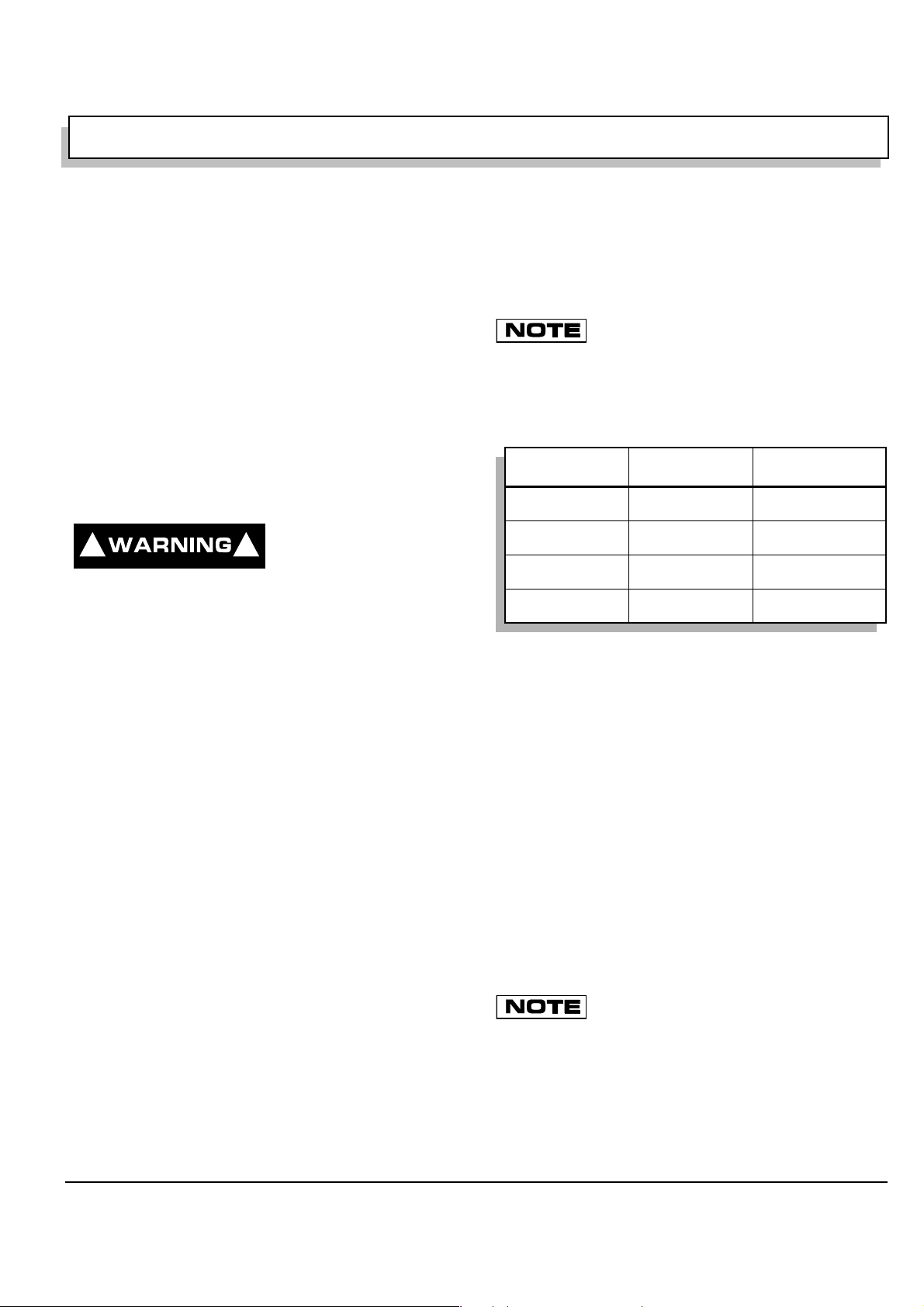
OPERATION AND SERVICE INFORMATION
Read all of manual to become thoroughly familiar with this vehicle. Pay particular attention to all Notes, Cautions and Warnings
Stay in designated areas and avoid extremely
rough terrain.
Maintain a safe speed when driving down hill. Use
service brake to control speed when traveling
down an incline. A sudden stop or change of
direction may result in loss of control.
To prevent loss of control, do not move the direction selector of a PDS vehicle while the vehicle is
in motion. Moving the selector will result in a sudden slowing of the vehicle and the beeping of a
warning device.
Slow down before and during turns. All turns
should be made at reduced speed.
Never drive vehicle up, down, or across an incline
that exceeds 14° (25% grade).
To reduce the possibility
! !
of severe injury or death
resulting from improper
vehicle operation, the following warnings must be
observed:
Refer to GENERAL SPECIFICATIONS for seating
capacity.
Depressing accelerator pedal will release foot
operated park brake and may cause inadvertent
vehicle movement. Turn the key to the ‘OFF’ position whenever the vehicle is parked.
To prevent inadvertent movement when the vehicle is to be left unatt ended, engage the park
brake, move direction selector to forward position, turn key to ‘OFF’ position and remove key.
Make sure that the direction selector is in correct
position before attempting to start the vehicle.
Always bring the vehicle to a complete stop
before shifting the direction selector.
Do not take vehicle out of ‘gear’ while in motion
(coast).
Check the area behind the vehicle before operating in reverse.
All occupants must be seated. Keep entire body
inside vehicle and hold on while vehicle is in
motion.
PRECISION DRIVE SYSTEM
Precision Drive System™ (PDS) vehicles are operated in
one of four modes or “performance opt ions”. All options
have standard features that control, protect and diagnose
the vehicle.
PDS vehicles operate only when the Run -
Tow/Maintenance switch is in the ’RUN’ position. See ‘RUN - TOW/MAINTENANCE SWITCH (PDS VEHICLES ONLY)’ on page 3.
™
Performance Options
The options are defined as follows:
Performance Option Top Speed
1. All Terrain
2. Steep Hill
3. Mild Hill
4. Freedom
Fig. 9 Performance Options
1. The All-Terrain performance option: T he vehicle ’s top
speed is sensed and regulated directly by the controller.
2. The Steep Hill performance option: This option
includes all of t he driving features and top speed of
All-Terrain plus pedal-up braking. This is the strongest of the two pedal-up braking options.
3. The Mild Hill performance option: This option includes
all of the driving features of the Steep Hill option,
except the pedal-up braking feel is milder and the top
speed is slightly higher.
4. The Freedom performance option: This option
includes all of the driving features of the All-Terrain
option except that the vehi cle’s top speed is the hi ghest available. This opti on is not offered on fleet golf
cars.
The Freedom option is not available for fleet
golf cars.
The vehicle performance option can be determined by
placing the vehicl e in dia gnostic mode. See Technician’s
Repair and Service Manual. T he n umber of bee ps heard
immediately after entering dia gnostic mode correspo nds
to the above option numbers.
13 - 13.5 mph
(21 - 22 kph)
13 - 13.5 mph
(21 - 22 kph)
14 - 14.5 mph
(22.5 - 23 kph)
17 - 19 mph
(27 - 30.5 kph)
Pedal-Up
Braking Strength
None
Heavy
Mild
None
Owner’s Manual and Service Guide
Page 5
 Loading...