

E-Z-GO FREEDOM, FREEDOM HP LE, FREEDOM SE, FREEDOM LE, SHUTTLE 2+2 Owner's And Service Manual
...
28681-G01-FR
OWNER’S MANUAL & SERVICE GUIDE
MANUEL D’EXPLOITATION
ET D’ENTRETIEN
GASOLINE POWERED FLEET GOLF CARS & PER-
VOITURETTES DE GOLF INDUSTRIELLES
A ESSENCE & VEHICULES PRIVES
A PARTIR DES MODELES DE L’ANNEE 2002
SNAL VEHICLES
STARTING MODEL YEAR 2002
REVISED 10-10-02
Mise à jour le 10-10-02

SAFETY
r
For any questions on material cont ained in this manual, conta ct an aut horized representative for clarification.
Read and understand all lab els located on the vehicle. Always replac e any dama ged or missing labels.
On steep hills it is possible for vehicles to coast at greater than normal speeds encountered on a flat surface. To pre-
vent loss of vehicle control and possible serious injury, speeds should be limited to no more than the maximum speed
on level ground. See GENERAL SPECIFICATIONS. Limit speed by applying the servi ce brake.
Catastrophic damage to the drivetrain components due to excessive speed may result from driving the vehicle above
specified speed. Damage caused by excessive speed may cause a loss of vehicle control, is costly, is considered
abuse and will not be covered under warranty.
Use extra caution when towing the vehicle(s). Do not tow a single vehicle at speeds in excess of 12 mph (19 kph). Do
not tow more than three vehicles at a time. Do not exceed 5 mph (8 kph) while towing multiple vehicles. Towing the
vehicle at above the recommended speed may result in personal injury and/or damage to the vehicle and other property.
Signs similar to the ones illustrated should be used to warn of situations that coul d result in an unsafe condition.
BATTERY WARNING
Battery posts,
terminals and related
accessories contain
lead and lead compounds,
chemicals known
to cause cancer and
reproductive harm.
WASH HANDS
AFTER HANDLING!
BATTERIES
AND RELATED PARTS
CONTAIN LEAD
WASH HANDS
AFTER HANDLING!
WARNING: Battery posts, terminals and related
accessories contain lead and lead compounds,
chemicals known to cause cancer and reproductive harm.
Be sure that this manual remains as part of the permanent service record should the vehicle be sold.
NOTES, CAUTIONS AND WARNINGS
Throughout this guide NOTE, CAUTION and WARNING
will be used.
A NOTE indicates a condition that should be
observed.
A CAUTION indicates a condition that
may result in damage to the vehicle.
A WARNING indicates a
! !
hazardous condition that
could result in severe
injury or death.
! !
quantities, to cause cancer, birth defects, or other
reproductive harm.
The exhaust emissions of this vehicles’ engine
complies with regulations set forth by the Environmental Protection Agency (EPA) of the United States of
America (USA) at time of manufacture. Significant fines could
result from modifications or tampering with the engine, fuel,
ignition or air intake systems.
Engine exhaust from this
product contains chemicals known, in certain
!
<
14
˚
25
%
DO NOT
DRIVE ACROSS
SLOPES IN
EXCESS OF 14˚
Observe these NOTES, CAUTIONS and WARNINGS;
be aware that servicing a vehicle requires mechanical
skill and a regard for conditions that could be hazardous.
Improper service or repair may damage the vehicle or
render it unsafe.
(NOTES, CAUTIONS AND WARNINGS CONTINUED ON INSIDE OF BACK COVER)
Battery posts, terminals
! !
and related accessories
contain l ead and lead
compounds. Wash hands after handling.
This spark ignition system meets all require-
ments of the Canadian Interference-Causing
Equipment Regulations.
Ce système d'allumage par étincelle de véhicule respecte
toutes les exigences du Règlement sur le matériel brouilleu
du Canada.

OWNER’S MANUAL
AND SERVICE GUIDE
GASOLINE POWERED
FLEET GOLF CARS
& PERSONAL VEHICLES
FLEET GOLF CAR
FREEDOM
™
FREEDOM™ SE
™
FREEDOM
FREEDOM
FREEDOM
FREEDOM
™
™
SHUTTLE
TEXTRON Golf, Turf & Specialty Products reserves the right to make design changes without obligatio n to make these changes on units previous ly so ld and the
informat i on contained in this manual is subject to change without notic e.
TEXTRON Golf, Turf & Specialty Products is not liable for errors in t hi s manual or for incidental or consequential damages that result from the use of the material in
this manual.
LE
™
HP
HP SE
HP LE
™
2+2
CUSTOMER SERVICE DEPARTMENT IN USA PHONE: 1-800-241-5855 FAX: 1-800-448-8124
Owner’s Manual and Service Guide
Page i

GENERAL INFORMATION
This vehicle has been designed and manufactured in the United States of America (USA) as a ‘World Vehicle’. The Standards
and Specifications listed in the followin g te xt originate in the USA unless othe rwise indicated.
The use of non Original Equipment Manufacturer (OEM ) ap pr oved parts may void the warranty.
Overfilling battery may void the warranty.
Tampering with or adjusting the go vernor to permit vehicle to operate at abov e factory specifications will void the vehicle
warranty.
When servicing e ngines, all ad justm ents an d rep laceme nt co m ponents m ust be per origi nal vehi cle spec ifica tions i n or der to
maintain the United States of America Federal and State emission certific at ion applicable at the time of manuf acture.
BATTERY PROLONGED STORAGE
All batteries will self discharge over time. The ra te of self di sch ar ge va rie s dep endin g on th e ambie nt te mp er a ture and th e age
and condition of the batte ries .
A fully charged battery wi ll not freeze in winter temperatur es unless the temperatur e fal ls below -7 5° F (-60° C ) .
Page ii
Owner’s Manual and Service Guide

TABLE OF CONTENTS
SAFETY ........ .. ............ .................... ............ .................... ............ .................... ....... Ins ide covers
NOTES ........................................................................................................................................ ii
SAFETY INFORMATION............................................................................................................ v
BEFORE IN ITIAL USE .............. ........... ..................... ........... ..................... ........... ..................... 1
Fig. 1 Initial Service Chart .........................................................................................................1
CONTROLS AND INDICATORS ...............................................................................................1
KEY/LIGHT SWITCH ...........................................................................................................................................1
DIRECTION SELECTOR .....................................................................................................................................2
CHOKE . .............. ............... .............. .............. ............ .............. .............. ............... ...............................................2
FUEL GAUG E ... .. ............... .............. .............. .......................... .............. ............... ...............................................2
LOW OIL PRESSURE INDICATOR LIGHT .........................................................................................................2
ACCELERATOR PEDAL .....................................................................................................................................2
COMBINATION BRAKE AND PA R K BRAKE PEDAL ....... ... ... .......................... .............. .......................... ..........3
HORN ...... ....................... .............................................. .................................. .....................................................3
OPERATING THE VEHICLE ..................................................................................................... 3
RUN-IN ................................................................................................................................................................4
COLD START I NG ......................... ............... .............. .............. .......................... .............. ....................................4
STARTING AN D DRIVING ............................ ............... ......................... ............... .............. .................................4
STARTING THE VEHICLE ON A HILL ................................................................................................................4
COASTING ............... ................. ............... ................. ................. ................. ............... .........................................5
FUEL ................... ............... .............. .............. .......................... .............. ............... ...............................................5
BATTERY .............. ................................... ............................................. ..............................................................5
LABELS AND PICTOGRAMS .............................................................................................................................5
SUN TOP AND W IND S H IE L D ... ... ............... .............. .............. .......................... .............. ............... .....................5
VEHICLE CLEANING AND CARE .................................. .. .... .. ........................ .. .... .. ..................6
VEHICLE CLEANING ..........................................................................................................................................6
VEHICLE CARE PRODUCTS ................................................................................................. ... .........................6
REPAIR .......... ............ ......... ........... ............ ......... ........... ............ ........... ......... ............ ................ 7
LIFTING THE VEHICLE ......................................................................................................................................7
WHEELS AND TIRES .................. .......................... .............. .......................... .............. .......................................7
LIGHT BULB REPLACEMENT ............................................................................................................................8
FUSE REPLAC E M E N T ........ .. ... ............... ......................... ............... .............. .............. .......................................8
VEHICLE WITH A DISCHARGED BATTERY .....................................................................................................8
TRANSPORTING VEHICLE ...................................................................................................... 9
TOWING ..... .............. ................. .................. ................. .............. ................. ................. .......................................9
NEUTRAL LOCK ...............................................................................................................................................10
HAULING . ........... ............ ........ ............ ........... ............ ........ ............ ........... ............ ........ .....................................10
SERVICE AND MAINTENANCE ..................................................... .. .... .......................... .... ....11
SERIAL NUMBER PLATE LOCATION ..............................................................................................................11
Fig. 2 Key/Light Switch, Low Oil Pressure Light and Fuel Gauge ............................................2
Fig. 3 Direction Selector ...........................................................................................................2
Fig. 4 Choke .............................................................................................................................2
Fig. 5 Accelerator and Brake Controls ......................................................................................3
Fig. 6 Horn Button .....................................................................................................................3
Fig. 7 Check Oil Level on Dipstick ............................................................................................4
Fig. 8 Fueling ............................................................................................................................5
Fig. 9 Lifting the Vehicle ...........................................................................................................7
Tire Repair .......................... .............. ............... ......................... ............... .............. .................................7
Wheel Installation ...................................................................................................................................8
Fig. 10 Wheel Installation .........................................................................................................8
Fig. 11 Headlight, Turn Signal & Marker Light Bulb Replacement ...........................................9
Fig. 12 Tail and Brake Light Bulb Replacement .......................................................................9
On Rear Axle ........................................................................................................................................10
Fig. 13 Neutral Lock on Rear Axle ..........................................................................................10
On Direction Selector ............................................................................................................................10
Fig. 14 Neutral Lock on Direction Selector .............................................................................10
Owner’s Manual and Service Guide
Page iii

TABLE OF CONTENTS
Early Produ ct io n ........ ... ... .............. .............. ............... .............. .......................... .................................. 11
Fig. 15 Serial Number Plate Location - Early Production ....................................................... 11
Late Produc ti on ......................................... .............. .............. .............. .......................... ....................... 11
Fig. 16 Serial Num b e r Pla te Lo ca ti o n - Late Pr o duc t ion ............. ... .............. .......................... 12
PERIODIC SERVICE SCHEDULE .................................................................................................................. 13
TIRE INSPE CT IO N .. ... .. ............... .............. .............. .......................... .............. ............... .................................. 15
CHECKING THE OIL LEVEL ............................................................................................................................ 15
CHANGIN G TH E OIL .. .............. .............. .......................... .............. ............... .............. ..................................... 15
STARTER/ GENERATOR BE LT TENSION ...... ... .............. .......................... .............. .......................... .............. 17
BATTERY CLEANING ...................................................................................................................................... 18
BRAKES ........................................................................................................................................................... 19
AIR INTAKE AND COOLING FINS ................................................................................................................... 20
REAR AXLE . ... .......................... .............. ............... ......................... ............... ................................................... 20
AIR CLEANER INSPECTION AND REPLACEMENT ....................................................................................... 20
LUBRICA TION ......... .............. .............. ............ .............. .............. ............... ........... ........................................... 21
SPARK PLUGS ................................................................................................................................................. 21
DIRECTION SELECTOR (Dual Cable system) ................................................................................................ 22
PROLONGED STORAGE ................................................................................................................................ 22
HARDWARE ....................... ................................... ............................................. .............................................. 22
CAPACITIES AND REPLACEMENT PARTS ................................................................................................... 23
GENERAL SPECIFICATIONS.................................................................................................. 25
TXT GASOLINE - FLEET .................................................................................................................................. 26
TXT GASOLINE - FREEDOM™ ........................................................................................................................ 27
TXT GASOLINE - FREEDOM™ SE .................................................................................................................. 28
TXT GASOLINE - FREEDOM™ LE................................................................................................................... 29
TXT GASOLINE - FREEDOM™ HP.................................................................................................................. 30
TXT GASOLI N E - FRE ED O M ™ H P SE .............. ... .............. .......................... .............. .............. ............. .......... 31
TXT GASOLI N E - FRE ED O M ™ H P LE...... .............. ............... ......................... ............... .............. .................... 32
TXT GASOLINE - SHUTTLE™ 2+2................................................................................................................... 33
LIMITED WARRANTIES...........................................................................................................37
DOMESTIC W AR RANTY ............. .............. .............. .......................... .............. ............... .............. .................... 38
Fig. 17 Periodic Service Schedule ......................................................................................... 13
Fig. 18 Clean Entire Dipstick ............. .................. ............................ .................. .....................15
Fig. 19 Check Oil Level on Dipstick ....................................................................................... 15
Fig. 20 Oil Viscosity Chart ...................................................................................................... 16
Fig. 21 Clean Top of Engine ........... ......... ............................ ......... ......... ............................ .... 16
Fig. 22 Remove Oil Filter ....................................................................................................... 16
Fig. 23 Clean Oil Filter ................... ......... ........................... .................................................... 16
Fig. 24 Blowing Out Oil Filter ................................................................................................. 16
Fig. 25 Add Engine Oil ........................................................................................................... 17
Fig. 26 Checking Belt Tension with Gauge ............................................................................ 17
Fig. 27 Checking Belt Tension Manually ................................................................................ 17
Adjusting the Belt ................................................................................................................................. 18
Fig. 28 Adjusting Belt Tension ............................................................................................... 18
Fig. 29 Preparing Acid Neutralizing Solution .......................................................................... 18
Periodic Brake Test for Mechanical Brakes ......................................................................................... 19
Fig. 30 Typical Brake Performance Test ................................................................................ 19
Fig. 31 Cleaning Ai r Intake ............................... ......... ......... .......... ......... ......... ......... ............... 20
Fig. 32 Cleaning the Cooling Fins ......................... ......... .................. ......................................20
Checking th e Lu b ric an t Le ve l ........ ... ... .............. .............. ............... .............. .......................... .............. 20
Fig. 33 Add, Check and D r ain Rear Axle Lubric ant .......... ..................................................... 20
Cleaning th e Air F ilt er El e men t ....................................... ............... .......................... .............. . ............. 21
Fig. 34 Air Cleaner ................................................................................................................. 21
Fig. 35 Lubrication Points - Early Production ......................................................................... 21
Fig. 36 Lubrication Points - Late Production .......................................................................... 21
Fig. 37 Shift Cable Adjustment ............................................................................................... 22
Fig. 38 Torque Sp e ci fic a tio ns .......................... .............. .............. ............... ......................... ...23
Fig. 39 Capacities and Replacement Parts ............................................................................ 23
Fig. 36 Vehicle Dimensions.....................................................................................................34
Fig. 37 Vehicle Dimensions, Incl ine Specifications and Turning Clearance Diamet er............ 35
Page iv
Owner’s Manual and Service Guide

TABLE OF CONTENTS
INTERNAT IO N A L WAR RANTY (2002).......... ... ... .............. ............... .............. .......................... .........................39
INTERNAT IO N A L WAR RANTY (2003).......... ... ... .............. ............... .............. .......................... .........................40
FEDERAL EMIS SION COMPONE N T D EF EC T W AR RA N T Y .... .............. .......................... .............. ............... ..41
CALIFORNIA EMISSIO N CO NT R O L W ARRANTY STAT E M ENT.... ... .. ... .......................... .......................... ..... 4 3
DECLARATION OF CONFORMITY (EUROPE ONLY)............................................................47
FLEET GOLF C AR ( 20 0 0)..... .............. .............. ............... .............. .......................... .............. ............................48
FREEDOM™ GOLF CAR (2000) .......................................................................................................................49
FREEDOM™ HP GO L F CAR (200 0 ) ............. ............... .............. .............. ............... .............. ............................50
SHUTTLE 2+ 2 (200 0 ).............. ............... .............. .......................... .............. .......................... ............................51
FLEET AND FR EE D O M ™ GO LF CAR (20 0 2)...................... .......................... .............. ............... ......................52
SHUTTLE 2+ 2 (200 2 ).............. ............... .............. .......................... .............. .......................... ............................53
LABELS AND PICTOGRAMS.................................................................................. Appendix A
Owner’s Manual and Service Guide
Page v

N
TABLE OF CONTENTS
otes:
Page vi
Owner’s Manual and Service Guide

SAFETY INFORMATION
This manual has been designed to assist in maintaining the vehicle in accordance with procedures developed by the
manufacturer. Adherence to these procedures and troubleshooting tips will ensure the best possible service from the product.
To reduce the chance of personal i nj ury or property damage, the fol low in g m ust be carefully observed:
GENERAL
Many vehicles are us ed for a variety of tasks beyond the or iginal intended use of the veh icle; therefore, it is impossi ble to
anticipate and wa rn against every possible combin at io n of circumstances that may oc cu r. No warnings can take the place of
good common sense and prudent driving practices.
Good commo n sense and prudent driving practices do m ore to prevent acci dents and injury than all of the warnings and
instructions combined. The manufacturer strongly suggests that all users and maintenance personnel read this entire manual
paying particular attention to the CAU TIONS and WARNINGS con tained ther ei n.
If you have any questions regarding this vehicle, contact your closest representative or write to the address on the back cover
of this publication, Attention: Pro duct Service Department.
TEXTRON Golf, Turf & Specialty Products reserves the right to make design changes without obligation to make these
changes on units previousl y sold and the informatio n conta in ed in th is ma nual is subject to change without notice.
TEXTRON Golf, Turf & Specialty Products is not liable for error s in this manual or for inc idental or consequen tial damages
that result from the use of the m at er i al in this m anual.
This vehicle conform s to th e cur re nt appl i cab le stand ar d(s ) for saf ety and performance requir em ents .
These vehicles are designed and manufactured for off-road use. They do not conform to Federal Motor Vehicle Safety
Standards of the United States of America (USA) and are not equippe d for operation o n public streets. Some communities
may permit these veh ic le s to be operated on their streets on a lim ited b asis and in accordance w ith local ordinances.
Refer to GENERAL SPEC I FI CATIONS for vehicle seating capacity.
Never modify the vehicle in any way that will alter the weight distribution of the vehicle, decrease its stability or
increase the speed beyond the factory specification. Such modifications can cause serious personal injury or death.
Modifications that increase the speed and/or weight of the vehicle will extend the stopping distance and may reduce the
stability of the vehicle. Do not make any such modifications or changes. The manufacturer prohibits and disclaims
responsibility for any such modifications or any oth er alter at io n w hi ch would adversely affect the saf et y of the vehicl e.
Vehicles that are capable of higher speeds must limit their speed to no more than the speed of other vehicles when used in a
golf course environment. Additionally, speed should be further moderated by the environmental conditions, terrain and
common sense.
Always:
• Use the vehicle in a responsible manner and maintain the vehicle in safe operating condition.
• Read and observe all warnings and operation inst ruction labels affixed to the vehicle.
• Follow all safety rules established in the area where the vehicle is being operated.
• Reduce speed to compensate for poor terrain or conditions.
• Apply service brake to control speed on steep grades.
• Maintain adequate distance between vehicles.
• Reduce speed in wet areas.
• Use extreme caution when approaching sharp or blind turns.
• Use extreme caution when driving over loose terrain.
GENERAL OPERATION
Owner’s Manual and Service Guide
Page vii

SAFETY INFORMATION
• Use extreme caution in areas where pedestrians are present.
MAINTENANCE
Always:
• Maintain the vehicle in accordance with the manufacturer’s periodic service schedul e.
• Ensure that repairs are performed by those that are trained and qualified to do so.
• Follow the manufacturer’s maintenance procedures for the vehicle. Be sure to disable the vehicle before performing
any maintenance. Disabling includes removing the key from the key switch and removal of a battery wire.
• Insulate any tools used within the bat tery area in order to prevent sparks or battery explosion caused by shorting the
battery terminals or associated wiring. Remove the battery or cover exposed terminals with an insulating material.
• Use specified replacement parts. Never use replace men t parts of lesser quali ty.
• Use recommended tools.
• Determine that tools and procedures not specifically recommended by the manufacturer will not compromise the
safety of personnel nor jeopar dize the safe operation of the vehicl e.
• Support the vehicle using wheel chocks and jack stands. Never get under a vehicle that is supported by a jack. Lift
the vehicle in accordance with the manufacturer’s instructions.
• Empty the fuel tank or plug fuel hoses to prevent fuel leakage.
• Maintain the vehicle in an area away from exposed flame or persons who are smoki ng.
• Be aware that a vehicle that is not performing as designed is a potential hazard and must not be operated.
• Test driv e the vehicle after any repairs or maintenance. Al l t ests must be conducted in a safe ar ea that is free of both
vehicular and pedestrian traffic.
• Replace damaged or missing warning, caution or information labels.
• Keep complete records of the maintenance history of the vehicle.
The manufacturer cannot anticipate all situations, therefore people attempting to maintain or repair the vehicle must have the
skill and expe rience to re cogni ze and prot ect the msel ves f rom po tent ial situ ations t hat could resu lt in s evere perso nal injur y
or death and d amage to the vehicle. Use e xtreme caution and, if u nsure as to the potential fo r injury, refer the repair or
maintenance to a qualified mechanic.
VENTILATION
Always store gasol in e vehicles in a well ventilated are a . Ventilation prevents gasoline fumes from acc um ulat i ng.
Never fuel a vehicle in an area that is subject to flame or spark. Pay particular attention to na tural gas or propane wa ter
heaters and furnac es.
Never work a round or operate a vehicle in an environment that do es not ventilate exhaust ga ses from the area. Carb on
monoxide is a dangerous gas that can ca use unconsciousness and is potentially leth al.
Page viii
Owner’s Manual and Service Guide

SAFETY INFORMATION
Owner’s Manual and Service Guide
Page ix

Notes:
SAFETY INFORMATION
Page x
Owner’s Manual and Service Guide

SAFETY INFORMATION
Read all of manual to become thoroughly familiar with this vehicle. Pay part icu lar at tention to all Notes, Cautions and Warnings
GENERAL
The following tex t is pr ovided as recomm en ded by part II of
American Society of Mechanical Engineers / American
National Standards Institute (ASME/ANSI ) B56.8- 1988. Th e
manufacturer strongly endorses the contents of this
specification.
PART II
FOR THE USER
4 GENERAL SAFETY PRACTICES
4.1 Introduction
4.1.1 Like other machines, carriers can cause injury
if improperly used or maintained. Part II contains broad
safety practices applicable to carrier operations. Before
operation, the user shall establish such additional specific safety practices as may reasonably be required for
safe operation.
4.2 Stability
4.2.1 Experience has shown that this v ehicle , which
complies with this standard, is stable when properly
operated and when operated in accordance with specific
safety rules and practices established to meet actual
operating terrain and conditions. However, improper
operation, faulty maintenance, or poor housekeeping
may contribute to a condition of instability and defeat the
purpose of the standard. Some of the conditions which
may affect stability are failure of the user to follow safety
practices; also, ground and floor conditions, grade,
speed, loading, the operation of the carrier with improper
loads, battery weight, dynamic and static forces, and the
judgement exercised by the carrier operator.
(a) The user shall train carrier operators to adhere
strictly to the operating instructions stated in this Standard.
(b) The user shall survey specific operating conditions
and environment, and establish and train carrier operators to comply with additional, specific safety practices.
4.3 Nameplates, Markings, Capacity, and Modifica-
tions
4.3.1 The user shall maintain in a legible condition
all nameplates, warnings, and instructions which are
supplied by the manufacturer.
4.3.2 The user shall not perform any modification or
addition which affects capacity or safe operation, or
make any change not in accordance with the owner’s
manual without the manufacturer’s prior written authorization. Where authorized modifications have been made,
the user shall ensure that capacity, operation, warning,
and maintenance instruction plates, tags, or decals are
changed accordingly.
4.3.3 As required under paras. 4.3.1 or 4.3.2, the
manufacturer shall be contacted to secure new nameplates, warnings, or instructions which shall then be
affixed in their proper place on the carrier.
4.4 Fuel Handling and Storage
4.4.1 The user shall supervise the storage and han-
dling of liquid fuels (when used) to be certain that it is in
accordance with appropriate paragraphs of American
National Standards Institute/National Fire Protection
Association (ANSI/NFPA) 505 and ANSI/NFPA 30.
4.4.2 Storage and handling of liquefied petroleum
gas fuels shall be in accordance with appropriate paragraphs of ANSI/NFPA 505 and ANSI/NFPA 58. If such
storage or handling is not in compliance with these standards, the user shall prevent the carrier from being used
until such storage and handling is in compliance with
these standards.
4.5 Changing and Charging Storage Batteries for
Electric Personnel and Burden Carriers
4.5.1 The user shall require battery changing and
charging facilities and procedures to be in accordance
with appropriate parag raphs of ANSI/NFPA 505.
4.5.2 The user shall periodically inspect facilities
and review procedures to be certain that appropriate
paragraphs of ANSI/ NFPA 505, are strictly complied wi th,
and shall familiarize carrier operators with it.
4.6 Hazardous Locations
4.6.1 The user shall determine the hazard classifi-
cation of the particular atmosphere or location in which
the carrier is to be used in accordance with ANSI/NFPA
505.
4.6.2 The user shall permit in hazardous areas only
those carriers approved and of the type required by
ANSI/NFPA 505.
4.7 Lighting for Operating Areas
4.7.1 The user, in accordance with his responsibility
to survey the environment and operati ng condit ions, shall
determine if the carrier requires lights and, if so, shall
Owner’s Manual and Service Guide
Page xi

SAFETY INFORMATION
Read all of manual to become thoroughly f amiliar with th is vehicle. Pay particular attention to all Notes, Cautions and Warnings
equip the carrier with appropriate lights in accordance
with the manufacturer’s recommenda ti ons.
4.8 Control of Noxious Gases and Fumes
4.8.1 When equipment powered by internal com-
bustion engines is used in enclosed areas, the atmosphere shall be maintained within limits specified in the
American Conference of Governmental Industrial
Hygienists publication, “Threshold Limit Values for
Chemical Substances and Physical Agents in the Workroom Environment”. This shall be accomplished by ventilation provided by the user, and/or the installation, use,
and proper maintenance of emission control equipment
recommended or provided by the manufacturer of the
equipment.
4.9 Warning Device(s)
4.9.1 The user shall make periodic inspections of
the carrier to be certain that the sound-producing and/or
visual device(s) are maintained in good operating condition.
4.9.2 The user shall determine if operating conditions require the carrier to be equipped with additional
sound-producing and/or visual devices and be responsible for providing and maintaining such devices, in accordance with the manufacturer’s recommendations.
5 OPERATING SAFETY RULES AND
PRACTICES
5.1 Personnel and Burden Carrier Operator
Qualifications
5.1.1 Only persons who are trained in the proper
operation of the carrier shall be authorized to operate the
carrier. Operators shall be qualified as to visual, auditory,
physical, and mental ability to safely operate the equipment according to Section 5 and all other applicable
parts of this Standard.
5.2 Personnel and Burden Carrier Operators’
Training
5.2.1 The user shall conduct an operators’ training
program.
5.2.2 Successful completion of the operators’ training program shall be required by the user before operation of the carrier. The program shall be presented in its
entirety to all new operators and not condensed for those
claiming previous experience.
5.2.3 The user should includ e in the op erators ’ tra in-
ing program the following:
(a) instructional material provided by the manufac-
turer;
(b) emphasis on safety of passengers, material loads,
carrier operator, and other employees;
(c) general safety rules contained within this Standard
and the additional specific rules determined by the user
in accordance with this Standard, and why they were formulated;
(d) introduction of equipment, control locations and
functions, and explanation of how they work when used
properly and when used improperly, and surface conditions, grade, and other conditions of the environment in
which the carrier is to be operated;
(e) operational per formance t est s and e valuati ons during, and at completion of, the program.
5.3 Personnel and Burden Carrier Operator
Responsibility
5.3.1 Operators shall abide by the following safety
rules and practices in p aras. 5.4, 5.5, 5.6, and 5.7.
5.4 General
5.4.1 Safeguard the pedestrians at all times. Do not
drive carrier in a manner that woul d endanger anyone.
5.4.2 Riding on the carrier by pers ons other t han the
operator is authorized onl y on per sonnel seat (s ) provi ded
by the manufacturer. All parts of the body shall remain
within the plan view outline of the carrier.
5.4.3 When a carrier is to be left unattended, stop
carrier, apply the parking brake, stop the engine or turn
off power, turn off the control or ignition circuit, and
remove the key if provided. Block the wheels if machine
is on an incline .
5.4.4 A carrier is considered unattended when the
operator is 25 ft. (7.6 m) or more from the carrier which
remains in his view, or whenever the operator leaves the
carrier and it is not within his view. When the operator is
dismounted and within 25 ft. (7.6 m) of the carrier still in
his view, he still must have controls neutralized, and the
parking brake(s) set to prevent movement.
5.4.5 Maintain a safe distance from the edge of
ramps and platforms.
5.4.6 Use only approved carriers in hazardous locations, as defined in the appropriate safety standards.
5.4.7 Report all accidents involving personnel,
Page xii
Owner’s Manual and Service Guide

SAFETY INFORMATION
Read all of manual to become thoroughly familiar with this vehicle. Pay part icu lar at tention to all Notes, Cautions and Warnings
building structures , and equipment.
5.4.8 Operators shall not add to, or modify, the car-
rier.
5.4.9 Carriers shall not be parked or left unattended
such that they block or obstruct fire aisles, access to
stairways, or f ire equipment.
5.5 Traveling
5.5.1 Observe all traff ic regulati ons, i ncludi ng autho-
rized speed limits. Under normal traffic conditions keep
to the right. Maintain a safe distance, based on speed of
travel, from a carrier or vehicle ahead; and keep the carrier under control at all times.
5.5.2 Yield the right of way to pedestrians, ambulances, fire trucks, or other carriers or vehicles in emergency situations.
5.5.3 Do not pass another carrier or vehicle traveling in the same direction at intersections, blind spots, or
at other dangerous locations .
5.5.4 Keep a clear view of the path of travel,
observe other traffic and personnel, and maintain a safe
clearance.
5.5.5 Slow down or stop, as conditions dictate, and
activate the sound-producing warning device at cross
aisles and when visibili ty i s obstructed at other locatio n s.
5.5.6 Ascend or descend grades slowly.
5.5.7 Avoid turning, if possible, and use extreme
caution on grades, ramps, or inclines; normally travel
straight up and down.
5.5.8 Under all travel conditions the carrier shall be
operated at a speed that will permit it to be brought to a
stop in a safe manner.
5.5.9 Make starts, stops, turns, or direction reversals in a smooth manner so as not to shift the load,
endanger passengers, or overturn the carrier.
5.5.10 Do not indulge in dangerous a ctivi ties , such as
stunt driving or horseplay.
5.5.11 Slow down when approaching, or on, wet or
slippery surfaces .
5.5.12 Do not drive carrier onto any elevator unless
specifically authorized to do so. Approach elevators
slowly, and then enter squarely after the elevator car is
properly leveled. Once on the elevator, neutralize the
controls, shut off power, and set parking brakes. It is
advisable that all other personnel leave the elevator
before a carrier is allowed to enter or exit.
5.5.13 Avoid running over loose objects, potholes,
and bumps.
5.5.14 To negotiate turns, reduce speed to improve
stability, then turn hand steering wheel or tiller in a
smooth, sweeping motion.
5.6 Loading
5.6.1 Handle only stable and safely arranged loads.
When handling off-center loads which cannot be centered, operate with extra caution.
5.6.2 Handle only loads within the capacity of the
carrier as specified on the nameplate.
5.6.3 Handle loads exceeding the dimensions used
to establish carrier capacity with extra caution. Stability
and maneuverability may be adversely affected.
5.7 Operator Care of Personnel and Burden
Carriers
5.7.1 At the beginning of each shift during which the
carrier will be used, the operator shall check the carrier
condition and inspect the tires, warning devices, lights,
battery(s), speed and directional controllers, brakes, and
steering mechanism. If the carrier is found to be in need
of repair, or in any way unsafe, the matter shall be
reported immediately to the designated authority and the
carrier shall not be operated until it has been restored to
safe operating conditio n.
5.7.2 If during operation the carrier becomes unsafe
in any way, the matter shall be reported immediately to
the designated authority, and the carrier shall not be
operated until it has been restored to safe operating condition.
5.7.3 Do not make repairs or adjustments unless
specifically authorized to do so.
5.7.4 The engine shall be stopped and the operator
shall leave the carrier whi le refueling.
5.7.5 Spillage of oil or fuel shall be carefully and
completely absorbed or evaporated and fuel tank cap
replaced before st arting engine.
5.7.6 Do not operate a carrier with a leak in the fuel
system or battery(s).
5.7.7 Do not use open flames for checking electrolyte level in storage battery(s) or liquid level in fuel tanks.
6 MAINTENANCE PRACTICES
6.1 Introduction
Owner’s Manual and Service Guide
Page xiii

SAFETY INFORMATION
Read all of manual to become thoroughly f amiliar with th is vehicle. Pay particular attention to all Notes, Cautions and Warnings
6.1.1 Carriers may become hazardous if maintenance is neglected. Therefore, maintenance facilities,
trained personnel, and procedures shall be provided.
Such facilities may be on or off the pre mises.
6.2 Maintenance Procedures
6.2.1 Maintenance and inspection of all carriers
shall be performed in conformance with the manufacturer’s recommendations and the following pract ices.
(a) A scheduled preventive maintenance, lubrication,
and inspection system shall be followed.
(b) Only qualified and authorized personnel shall be
permitted to maintain, repair, adjust, and inspect carriers.
(c) Before undertaking maintenance or repair, follow
the manufacturer’s recommendations for immobilizing
the carrier.
(d) Block chassis before worki ng underneath it.
(e) Before disconnecting any part of the engine fuel
system of a gasoline or diesel powered carrier with gravity feed fuel systems, be sure shutoff va lve is closed, and
run engine until fuel syst em is depl eted and engine stops
running.
(f) Before disconnecting any part of the engine fuel
system of LP gas powered carriers, close the LP gas cylinder valve and run the engine until fuel in the system is
depleted and the engine stops runni ng.
(g) Operation to check performance of the car rier shall
be conducted in an authorized area where safe clearance exists.
(h) Before commencing operation of the carrier, follow
the manufacturer’s instructions and recommended procedures.
(i) Avoid fire hazards and have fire protection equipment present in the work ar ea. Do not use an open flame
to check level or leakage of fuel, battery electrolyte, or
coolant. Do not use open pans of fuel or flammable
cleaning fluids for cleaning parts.
(j) Properly ventilate the work area.
(k) Handle LP gas cylinders with care. Physical damage, such as dents, scrapes, or gouges, may dangerously weaken the tank and make it unsafe for use.
(l) Brakes, steering mechanisms, speed and directional control mechanisms, warning devices, lights, governors, guards, and safety devices shall be inspected
regularly and maintained in a safe operating condition.
(m) Special carriers or devices designed and
approved for hazardous area operation shall be
inspected to ensure that maintenance preserves the original approved safe operating features.
(n) Fuel systems shall be chec ked for l eak s and condition of parts. If a leak is found, action shall be taken to
prevent the use of the carrier until the leak has been
eliminated.
(o) The carrier manufa cturer’s capaci ty, operation, and
maintenance instruction plates, tags, or decals shall be
maintained in legible condition.
(p) Batteries, motors, speed and directional controllers, limit switches, protective devices, electrical conductors, and connections shall be inspected and maintained
in conformance with manufacturers recommended procedures.
(q) Carriers shall be kept in a clean condition to minimize fire hazards and facilitate detection of loose or
defective parts.
(r) Modifications and additions which affect capacity
and safe machine operation shall not be performed by
the customer or user without manufacturer’s prior written
authorization; where authorized modifications have been
made, the user shall ensure that capacity, operation,
warning, and maintenance instruction plates, tags, or
decals are changed accordingly.
(s) Care shall be taken to ensure that all replacement
parts are interchangeable with the original parts and of a
quality at least equal to that provided in the original
equipment.
End of ASME/ANSI B56.8 - 1988 Text
Page xiv
Owner’s Manual and Service Guide

SAFETY INFORMATION
Read all of manual to become thoroughly familiar with this vehicle. Pay part icu lar at tention to all Notes, Cautions and Warnings
GENERAL
The following tex t is pr ovided as recomm en ded by part II of
American National Standards Institute/National Golf Car
Manufacturers As sociation (ANSI/NGCMA ) Z130.1 - 1993.
The manufacturer, as a member of the NGCMA, strongly
endorses the contents of this specification.
PART II
MAINTENANCE AND OPERATIONS
5. GENERAL SAFETY PRACTICES
5.1. Introduction
Like other machines, golf cars can cause inj ury if improperly used or maintained. This section contains broad
safety practices recommended for safe golf car operations. Before operation, the controlling party should
establish suc h additional specific safety practices as may
be reasonably required for safe operations.
Experience has shown that golf cars which comply with
the provisions stated in Part II of this Standard are safe
when properly operated in accordance with the safety
and operation warnings affixed to every gol f car. The safe
operation is enhanced when the golf cars are operated
within a specific set of operation instructions, safety rules
and practices established to meet actual operating terrain and conditions.
The safety information contained in Part II is intended to
provide the controlling party with basic safety information
and to encourage the controlling party to implement a
golf car safety program.
It is suggested and recommended that Part II be
reprinted in the golf car manufacturer’s operation and
service manuals to encourage safe operations and practices at the controlling party’s facility.
5.2.1. Steep Grade
In areas where steep grades exist, golf car operations
should be restricted to the designated golf car pathways
where possible, and shall be identified with a suitable
warning giving the following information: “Warning, steep
grade, descend slowly with one foot on brake.”
5.2.2. Wet Areas
Wet grassy areas may cause a golf car to lose traction
and may affect stability. Wet areas shall be chained or
roped off to prevent golf car operat ions or be identi fied by
a suitable warning not to operate golf cars in this area
due to wet terrain.
5.2.3. Sharp Turns, Blind Corners, Bridge
Approaches
Sharp turns, blind spots, bridge approaches and other
potentially hazardous areas shall be either chained or
roped off to prevent golf car operations or identified with
a suitable warning to the operator of the nature of the
hazard and stating the proper precautions to be taken to
avoid the hazard.
5.2.4. Loose Terrain
Loose terrain may cause a golf car to lose traction and
may affect stability. Areas of loose terrain should be
repaired if possible, or chained or roped off to prevent
golf car operation or identified by a suitable warning to
operators not to operate golf cars in this area due to
loose terrain or possible hazardous conditions.
5.2.5. Golf Car/Pedestrian Interference Areas
5.2. Safety Survey
The controlling party shall perform a safety survey periodically, and as conditions warrant to their premises, to
identify areas where golf cars should not be operated
and to identify possible hazards.
Areas where pedestrians and golf cars interfere shall be
avoided whenever possible by rerouting the golf car traffic or the pedestrian traffic to eliminate the interfer ence. If
elimination of the interference is not possible or is highly
impractical, signs shall be erected warning pedestrians
of the golf car traffic and golf car operators of the pedestrian traffic and to drive slowly and use extreme caution.
Owner’s Manual and Service Guide
Page xv

SAFETY INFORMATION
Read all of manual to become thoroughly f amiliar with th is vehicle. Pay particular attention to all Notes, Cautions and Warnings
6. MAINTENANCE
6.1. Introduction
6.1.1. Golf cars may become hazardous if maintenance
is neglected or improperly performed. Therefore maintenance facilities, trained personnel and procedures in
accordance with the manufacturer’s recommendations
should be provided by the control ling party.
6.2. Preventive Maintenance
A regularly scheduled inspection and preventive maintenance program in accordance with the manufacturer’s
recommendations should be established. Such a program will be a valuable tool in providing the golfing
patron with a safe, properly operating golf car and
thereby help to avoid accidents.
6.2.1. Personnel
Only qualified, trained and authorized personnel shall be
permitted to inspect, adjust and maintain golf cars.
liters per car per charge. Because of the highly volatile
nature of hydrogen gas and its propensity to rise and
accumulate at the ceiling in pockets, a minimum of 5 air
changes per hour is recommended. The controlling party
shall consult applicable fir e and safet y codes for the specific ventilation levels required as well as the use of
explosion proof electrical apparatus.
6.2.4. Maintenance Procedures
All maintenance shall be performed in accordance with
the manufacturer’s recommended maintenance procedures as outlined in the manufacturer’s operation and
service manuals.
6.2.5. Maintenance Safety Procedures
All maintenance shall be performed in accordance with
the manufacturer’s recommended safety procedures as
outlined in the manufacturer’s operation and service
manuals. The following list of recommended safety procedures are general in nature and in no way supersede
the manufacturer’s specific instructions.
6.2.2. Parts and Materials
Only manufacturer’s recommended replacement parts
and materials shall be used.
6.2.3. Ventilation
Maintenance and storage areas shall be properly ventilated to avoid fire hazards in accordance with applicable
fire codes and ordinances.
6.2.3.1. Ventilation for gasoline powered golf cars shall
be provided to remove flammable vapors, fumes and
other flammable materials. Consult applicable fire codes
for specific levels of ventilation.
6.2.3.2. Ventilation for electric powered golf cars shall
be provided to remove the accumulation of flammable
hydrogen gas emitted during the charging process. The
amount of hydrogen gas emitted depends upon a number of factors such as the condition of the batteries, the
output rate of the battery charger and the amount of time
the batteries are on charge. Hydrogen emissions are
generally considered to be in the area of 10 to 20 cubic
6.2.5.1. Follow manufacturer’s instructions for immobilizing golf car before beginning any maintenance.
6.2.5.2. Block chassis before working underneath golf
car.
6.2.5.3. Before disconnecting any part of the fuel system, drain the system and turn all shut off valves to the
‘OFF’ position to prevent leakage or accumulation of
flammable fuels in the work area.
6.2.5.4. Avoid fire hazards and have fire protection
equipment available.
6.2.5.5. Before performing any maintenance on an electric golf car, disable the electrical system in accordance
with the manufacturer’s instructions.
6.2.5.6. Use only properly insulated tools when working
on electrically powered golf car s or around batteries.
6.2.5.7. Brakes, ste ering mechani sms, warning devices,
Page xvi
Owner’s Manual and Service Guide

SAFETY INFORMATION
Read all of manual to become thoroughly familiar with this vehicle. Pay part icu lar at tention to all Notes, Cautions and Warnings
governors and all other safety devi ces shall be inspected
and maintained in a safe and proper operating condition
and shall not be modified as supplied by the manufacturer.
6.2.5.8. After each maintenance or repair the golf car
shall be driven by qualified, trained and authorized personnel to ensure proper operation and adjustment.
6.2.5.9. Driving golf car to check for proper operation
and adjustment aft er repair shall be performed in an area
that is free of vehicular and pedestrian traffic.
6.2.5.10.Record all maintenance performed in a maintenance record log by date, name of person performing
maintenance and type of maintenance. Controlling party
management should periodically inspect maintenance
log to ensure currency and completenes s of entries.
7. FUELS HANDLING AND STORAGE/
BATTERY CHARGING
7.1. The controlling party shall supervise the storage
and handling of liquid fuels in accordance with appli cable
fire and safety requirements.
7.2. Storage and handling of liquefied petroleum gas
fuels shall be in accordance with American Gas Association recommendations and applicable fire safety requirements.
7.3. The controlling party shall require battery changing and charging facilities and procedures to be in accordance with applicable ordinances or regulations (also
see paragraph 6.2.3.2).
7.4. The controlling party shall periodically inspect
facilities and review procedures to be certain that the
procedures in paragraphs 6.2.3.2 and 7.3 are being followed.
6.2.5.11. Provide operator comment cards to assist in
identifying non-periodic maintenance needs for specific
golf cars.
6.2.6. The controlling party shall maintain in a legible
condition all nameplates, warnings and instructions
which are supplied by the manufacturer.
6.2.7. The controlling party shall not perf orm any modification or addition which affects capacity or safe operation, or make any change not in accordance with the
owner’s manual without the manufacturer’s prior written
authorization. Where autho rized modi ficat ions have been
made, the controlling party shall ensure that capacity,
operation, warning and maintenance instruction plates,
tags or decals are changed accordingly.
6.2.8. As required under paragraphs 6.2.6 and 6.2.7 the
manufacturer shall be contacted to secure new nameplates, warnings or instructions which shall then be
affixed in their proper place on the golf car.
8. OPERATING SAFETY RULES AND
PRACTICES
8.1. Operator Qualifications
8.1.1. Only authorized persons shall be allowed to oper-
ate golf cars. It is recommended that no persons be
allowed to operate golf cars except those persons who
posses a valid motor vehicle driver’s license.
8.1.2. The controlling party shall display the operation
and safety instructions as recommended by the golf car
manufacturers and the golf course safety rules in a conspicuous place near the golf car rental area or golf car
pick-up area. It is also recommended, as with all motor
vehicles, that the warning “Do not ope rate golf cars when
under the influence of alcohol or drugs.” be posted in a
conspicuous location.
Owner’s Manual and Service Guide
Page xvii

N
SAFETY INFORMATION
Read all of manual to become thoroughly f amiliar with th is vehicle. Pay particular attention to all Notes, Cautions and Warnings
otes:
Page xviii
Owner’s Manual and Service Guide
OPERATION AND SERVICE INFORMATION
Read all of manual to becom e th oroughly fam iliar with this vehicle. Pa y pa rt i cular attention to all Notes, Cautions and Warnings
Thank you for purchasing this vehicle. Before driving the
vehicle, we ask you to spend some time reading this
Owner’s Manual and Service Guide. This guide contains the
information that will assist you in maintaining this highly
reliable vehicle. Some i llustrations may show item s that are
optional for your vehicle. This guid e covers the ope ration of
several vehicles; therefore, some pictorial views may not
represent your ve hicle. Physical differences i n controls will
be illustrated.
This vehicle has been designed and manufactured as a
‘World Vehicle’. Some countries have individual
requirements to compl y with their specifications; therefor e,
some sections may not apply in your country.
Most of the service procedures in this guide can be
accomplished using common automotive hand tools.
Contact your serv ic e representative on servicing the vehicle
in accordance with the Pe riodi c Service Schedule.
Service Parts Manuals and Technician’s Repair and Se rvice
Manuals are available from a local Distributor, an authorized
Branch or the Service Parts Department. When ordering
parts or requesting information for your vehicle, provide
vehicle model, ser ial nu m ber and m anufacture date code.
BEFO R E INITIA L USE
Read, understand and follow the safety label on the
instrument panel . Be sure you unders tand how to operate
the vehicle, its equipment and how to use it safely.
Maintaining good per fo rmance depends to a la rg e ext en t on
the operator.
Hydrogen gas is generated
! !
concentration of hydrogen gas is explosive and could
cause severe injury or death. Charging must take place in
an area that is adequately ventilated (minimum of 5 air
exchanges per hour).
To reduce the cha nce of bat ter y ex plo sion th at cou ld r esu lt
in severe injury or death, never smoke around or charge
batteries in an area that has open flame or electrical
equipment that could cause an electrical arc.
Before a new vehicle is put into operat ion, the items shown
in the INITIAL SERVICE CHART must be performed (Ref.
Fig. 1 on page 1).
V ehicle battery must be f ully cha rged before ini t ial use .
Check for correct tire inflation. See GENERAL
SPECIFICATIONS.
Check for oil or fuel leaks that could have developed in
shipment from the factory.
as a natural part of the lead
acid battery charging
process. A 4%
Determine and record braking distance required to stop
vehicle for future brak e per f or ma nce tests.
Remove the protective clear plastic, that protect the seat
bottom and back rest during shipping, before placing the
vehicle in service.
ITEM SERVICE OPERATION
Battery Charge battery
Seats Remove protective plastic covering
Brakes Check operation and adjust if necessary
Establish acceptable stopping distance
Tires Check air pressure (see SPECIFICATIONS)
Fuel Fill tank with correct fuel
Engine Check oil level
Ref Isc 2
Fig. 1 Initial Service Chart
CONTROLS AND INDICA T O RS
Vehicle controls and indicators consist of:
• key/light switch
• directi on selector
• choke
• fuel gauge
• low oil pressure indicator light
• accelera tor pe dal
• combination service and
park brake pedal
• horn
KEY/LIGHT SWITCH
Located on the dash panel, this switch enables the basic
electrical system of the vehicle to be turned on and off by
turning the key. To prevent inadvertent operation of the
vehicle when left unattend ed, the key should be turned to
the ‘OFF’ position and rem ov ed ( R ef . Fig. 2 on page 2) .
If the vehicle is equipp ed with lights, the key switch has a
position to operate the m , indicated by the light icon.
If the vehicle is equipped with factory installed
custom accessories, some accessories remain
operational with the key switch in the ‘OFF’ position.
DIRECTION SELECTOR
To reduce the possibility of component
damage, the vehicle must be completely
stopped before moving the direction
selector.
Owner’s Manual and Service Guide
Page 1
OPERATION AND SERVICE INFORMATION
OFF
ON
F
UEL
R
R
R
Read all of manual to become thoroughly f amiliar with th is vehicle. Pay particular attention to all Notes, Cautions and Warnings
Low Oil Pressure
ef Kes 2
Key/Light Switch
OFF
ON
Indicator Light
Fuel
Gauge
E
F
Fig. 2 Key/Light Switch, Low Oil Pressure Light and
Fuel Gauge
Located on the seat support panel, this lever permits the
selection of either ‘F’ (forward) or ‘R’ (reverse) (Ref. Fig. 3
on page 2). Vehicle should be left in ‘F’ when unattend ed.
Reverse
ef Dsl 2
Forward
Fig. 3 Direction Selector
CHOKE
The choke is used to aid cold starting ( Ref. Fig. 4 o n page
2). See COLD ST ARTING section for operating instructions.
FUEL GAUGE
The fuel gauge (if equipped) will either be located on the
dash panel (elec tric) (Ref. Fig. 2 on page 2) or directl y on
the fuel tank (mechanical).
LOW OIL PRESSURE INDICATOR LIGHT
A low oil pressure indicator light is located on the dash panel
(Ref. Fig. 2 on page 2). The light illuminates when the oil
pressure is low. Check oil level. If oil level is between ADD
and FULL mark on dipstick, a mechanical problem exists
within the engine and the vehicle must not be driven.
Contact a local distribu to r or authorized branch.
Ref Chk 1
Choke
Fig. 4 Choke
check oil pressur e. If oil light does no t com e on, co ntinue to
use vehicle.
ACCELERATOR PEDAL
Unintentional movement of
! !
move which could result in severe injury or death.
With the key switch ‘ON’, depressing the accelerator pedal
starts the engine. When the pedal is released, the engine
will stop (Ref. Fig. 5 on page 2) . To s top the vehicle more
quickly, depress the service brake.
the accelerator pedal will
releas e the pa rk br ak e an d
may cause the vehicle t o
Park
Brake
Service
Brake
PARK
To prevent engine damage, do not
operate engine until oil pressure is
corrected. Do not overfill engine. Too
much oil may cause smoking or allow oil to enter the air filter
enclosure.
If oil level is below ADD mark on dipstick, add oil to bring
level to FULL mark. Drive vehicle a short distance and
Page 2
ef Abc 1
Accelerator
Fig. 5 Accelerator and Brake Controls
If key switch is ‘ON’ and park brake is set, depressing the
accelerator inadvertently will release the park brake and will
Owner’s Manual and Service Guide
OPERATION AND SERVICE INFORMATION
Read all of manual to become thoroughly familiar with this vehicle. Pay part icu lar at tention to all Notes, Cautions and Warnings
cause the vehicle to move which could cause severe inj ury
or death.
Depressing the accele ra to r p eda l will release the par k brake
if it is engaged. This is a feature to assure the vehicl e is not
driven with the park brake engaged. Depressing the
accelerator p edal is not the pr eferred method o f releasing
the park brake.
Depressing the lower section of the brake
pedal is the preferred method of releasing the
park brake to assure the longest service life of brake
components.
COMBINATION BRAKE AND PARK BRAKE
PEDAL
The brake pedal incorporates a park brake feature (Ref. Fig.
5 on page 2). To engage, push down on the upper section of
the pedal until it loc ks in place. The park brake will releas e
when the service brak e pedal is depressed. Use the lower
section of the brake pedal to operate the service brake
system.
HORN
The horn is operate d by pus hing the h orn but ton loc ated on
the floor to the left of the brake pedal (Ref. Fig. 6 on page 3).
Horn
R
N
O
H
PARK
conditions and the environmental factors which effect
the terrain and the ability to control the vehicle.
Use extra care an d reduced speed when drivi ng on
poor surfaces, such as loose dirt, wet grass, gravel,
etc.
Stay in designated areas and avoid extremely rough
terrain.
Maintain a safe speed when driving down hill. Use
service brake to co nt ro l spe ed wh en tra veling do wn an
incline. A sudden stop or change of direction may
result in loss of control.
Slow down befo re and dur ing tu rns. All t urns s hould
be made at reduced speed.
Never drive vehicle up, down, or across an incline that
exceeds 14° (25% grade).
To reduce the possibility of
! !
severe injury or death
resulting from improper
vehicle operation, the
following warnings must be observed:
Refer to GENERAL SPECIFICATIONS for seating
capacity.
Depressing accel erator pedal will release foot
operated park brake and may cause inadve rtent
vehicle movemen t. Turn the key to th e ‘OFF’ posi tion
whenever the vehicle is parked.
To prevent inadvertent movement when the vehicle is
to be left unattended, enga ge the park brake, move
direction selector to forward position, turn key to
‘OFF’ position and remove key.
Ref Hor 1
Fig. 6 Horn Button
OPERAT ING THE VEHICLE
Improper use of the vehicle or the lack of
proper maintenance may result in damage
or decreased performance.
Read and understand the following warnings before
attempting to operat e th e vehicle.
To reduce the possibility of
! !
following warnings must be observed:
When driving vehicle, consider the terrain , traffic
severe injury or death
resulting from loss of
vehicle control, the
Make sure that the direction selector is in correct
position before attempting to start the vehicle.
Always bring the vehi cle to a comple te stop before
shifting the direction selecto r.
Do not take vehicle out of ‘gear’ while in motion
(coast).
Check the area behind the vehicle before operating in
reverse.
All occupants must be seated. Keep ent ire body inside
vehicle and hold on while vehicle is in motion.
RUN-IN
Check for oil or fuel leaks that could have developed in
shipment from th e factor y. Avoid full throttle starts and rapid
acceleration until the engine has achieved operating
temperature.
All engines consu me more oil than normal during the f irst
hours of operation. As internal moving parts are run-in, oil
Owner’s Manual and Service Guide
Page 3
OPERATION AND SERVICE INFORMATION
Ref
Read all of manual to become thoroughly f amiliar with th is vehicle. Pay particular attention to all Notes, Cautions and Warnings
consumption should gradually decrease until the rate of
consumption stabilizes.
Check the oil level per the Periodic Service Schedule (Ref.
Fig. 17 on page 12). Add oil if the level on the dipstick
indicates that oil is in the add oil range (Ref . Fig. 7 on page
4).
Do not overfill engin e. Too much oil may
cause smoking or allow oil to enter the air
filter enclosure.
Both the oil dipstick and fill cap must be in
place before operating the engine. Failure to
install the dipstick and fill cap will result in oil becoming
contaminated and/or being discharged into the engine
compartment.
The oil should be changed in accordance with the Periodic
Service Schedule wh ile the engine is warm. See SERVICE
AND MAINTENANCE for checking oil level and changing oil
procedures.
Dsk 1
Maximum oil level
DO NOT OVERFILL
Add
oil
Fig. 7 Check Oil Level on Dipstick
Safe
operating range
Full
COLD STARTING
Starting a cold engine may require use of the choke.
Depress the acce lerator approximately 1" ( 2.5 cm) or until
the starter just begins to operate. Pull the choke out if
required. Accelerate slowly and push the choke in
completely when the engine runs smoothly.
Do not allow the starter to operate
continuously for more than 10 seconds.
Allow 30 seconds between starting
attempts. If the vehicle does not start on the third attempt, turn the
key switch off, set the park brake and determine the cause of the
problem.
If the vehicle had been running and the engine does not
start within 10 seconds , us e th e chok e.
STARTING AND DRIVING
To reduce the possibility of
! !
release service brake until engine has started.
roll-back which could
result in severe injury or
vehicle dama ge, do not
To operate vehicle:
• Apply the service brake, place the key in the key
switch and turn it to the ‘ON’ position.
• Move the direction selector to the direction desired.
• Release the park brake by depressing the service
brake pedal until the park brake releases.
• Slowly depress the accelerator pedal to start the
engine. Release service brake when engine starts.
• When the ac celerator pedal is released, the ignitio n
circuit is de- energize d a nd th e engine stops. To stop
the vehicle more qui ckly, depress the service b rake
pedal.
When the direction selector is in the reverse
position, a warning signal will sound to indicate
that the vehicle is ready to run in reverse.
STARTING THE VEHICLE ON A HILL
To reduce the possibility of
! !
roll-back which could
result in severe injury or
vehicle dama ge, do not
release service brake until engine has started.
Do not hold vehicle on hill by using
accelerator and engine. This will cause
premature and excessive wear to drive
train components.
To reduce the possibility of perm anent damage t o the drive
system, it is important to prevent exc essive roll-back when
starting the vehicle on a hil l.
Place left foot on service bra ke and release the par k brake.
Depress accelera tor with right foot and release the service
brake by lifting left foot.
COASTING
To reduce the possibility of
! !
severe injury or death from
coasting at above
recommended speeds, limit
speed with service brake.
On steep hills, it is possible for the vehicle to coast at
greater than normal speeds encountered on a flat surface.
To reduce the possible loss of vehicle control and severe
drivetrain damage, speeds should be limited to no more
than the maximum governed speed on level ground (see
GENERAL SPECIFICATIONS). Limit speed by applying
service brake.
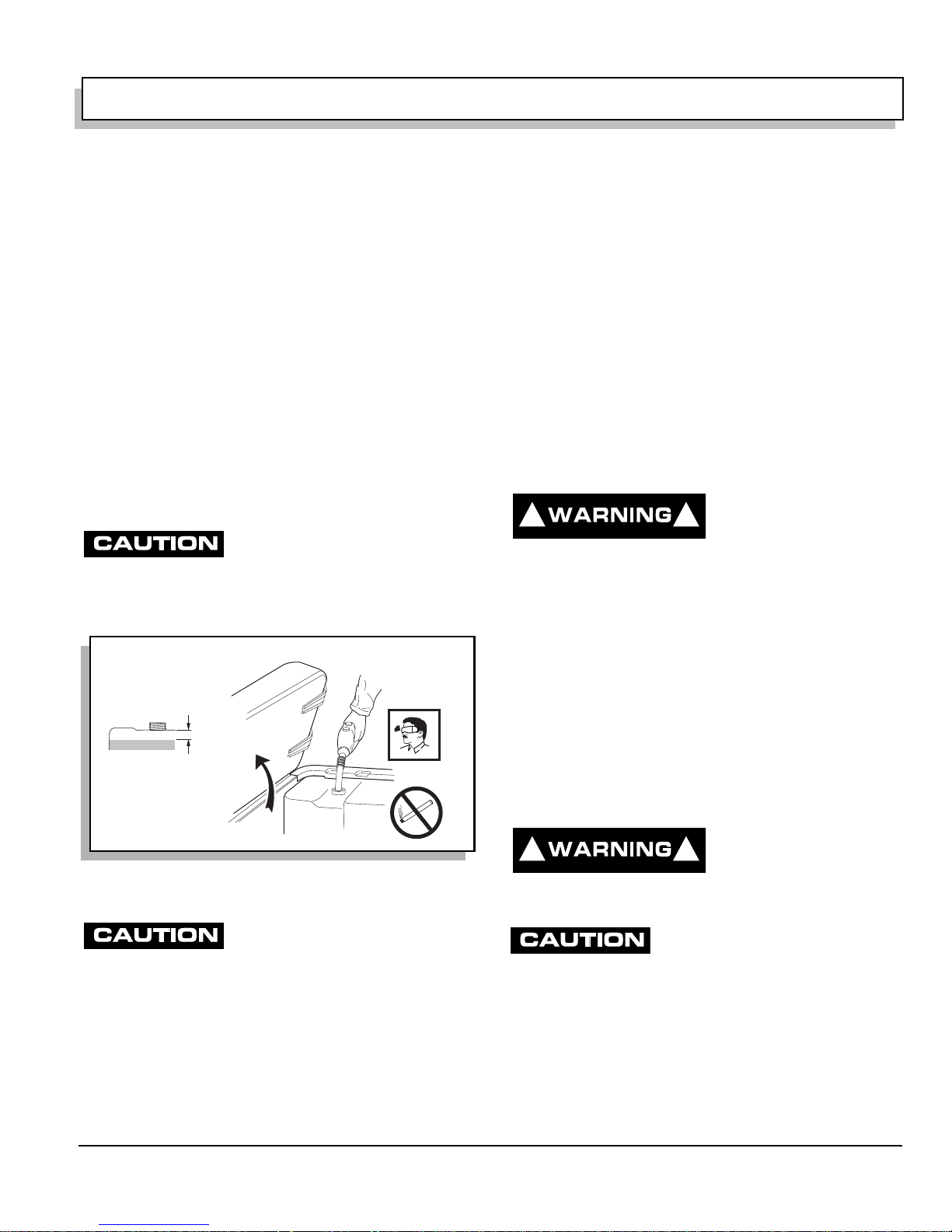
FUEL
To reduce the possibility of
! !
severe injury or death from
improper fuel handling:
Page 4
Owner’s Manual and Service Guide
OPERATION AND SERVICE INFORMATION
Read all of manual to become thoroughly familiar with this vehicle. Pay part icu lar at tention to all Notes, Cautions and Warnings
Do not smoke near the fuel tank.
Do not refuel near open flam e or electr ical ite ms wh ich
could produce a spark.
Always handle gasoline in a well ventilated area.
Always wear eye protection to protect against
splashed fuel and fuel vapors.
Always allow adequate space for the expansion of
gasoline. Leave at least 1" (2.5 cm) space below
bottom of filler neck.
Inspect fuel cap, tank and other components for leaks
or deterioration that co uld cause a hazardous
condition.
The fuel tank is located under the seat on the passenger
side of the vehicle (Ref. Fig. 8 on page 5). Fill the tank with
fresh, clean, automotive grade gasoline (Ref. Fig. 39 on
page 22). High alt itude or heav y use/load app lications may
benefit from higher oc tane gasoline.
Do not use gasoline whic h contain s M et hanol.
Some fuels, called oxygenated or
reformulated gasoline, are gasoline blended
with alcohols or ethers. Excessive amounts of
these blends can damage the fuel system or cause performance problems.
If any undesirable operating symptoms occur, use gasoline with a lower
percentage of alcohol or ether.
Fuel
1" Min.
(2.5 cm)
the battery even though the engine is running and the
generator operating. Discharging the battery is known as
deep cycling. The battery is not a deep cycle model, but is a
starting battery. Multiple deep cycling will result in the
premature failure of th e bat t ery.
If the vehicle battery has become discharged, it must be
charged using a 12 Volt charger that is rated at 10 amps or
less and in accordan ce with al l instruct ions provi ded by the
manufacturer of th e cha rger.
LABELS AND PICTOGRAMS
Vehicles may be labeled with pictograms as a method of
conveying information or warnings. Appendix A illustrates
and explains pictograms that may appear on the vehicle.
Not all pictograms shown in Appendix A will be found on
your vehicle.
SUN TOP AND WINDSHIELD
The sun top does not
! !
provide protection from roll
over or falling objects.
The windshield does not provide protection from tree
limbs or flying objects.
The sun top and winds hield provide some protection from
the elements; however, they will not keep the operator and
passenger dry in a d ownpour. This vehicle is not eq uipped
with seat belts and the sun top has not been design ed to
provide roll over protection. In addition, the sun top does not
protect against falling objects nor does the windshield
protect against flying obj ec ts and tre e lim bs. Keep arms and
legs inside of vehicle whi l e it is mo vi ng.
VEHICLE CLEANING AND CARE
Ref Ftl 1
Fig. 8 Fueling
BATTERY
Excessive use of accessories may drain
the battery and leave insufficient reserve
to start the vehicle.
The vehicle uses a combination starter/generator to both
start the engine an d charge th e battery. The engine will not
idle; therefore, the battery cannot be charged while the
vehicle is stopped. Do not operate accessory items (such as
accessory lights , radios, winch, etc.) e xcessively while the
vehicle is stopped.
The generator is capable of sup plying 35 amps; therefore,
operation of all acce ssories could resu lt in the discharge of
VEHICLE CLEANING
! !
supplied by manufacturer of pressure washer.
cosmetic damage, do not us e any abrasive or reactive so lvents to
clean plastic parts.
It is important that proper techniques and cleaning materials
be used. Using excessive water pressure may cause severe
injury to operator or bystander, damage to seals , plastics,
seat material, body fin ish or electrical system. Do not use
pressure in exce ss of 700 psi to wa sh exterior of vehicle.
Owner’s Manual and Service Guide
To reduce the possibility of
severe injury or vehicle
damage, read and
understand all instructions
When pressure washing exterior of
vehicle, do not use pressure in excess of
700 psi. To reduce the possibility of
Page 5
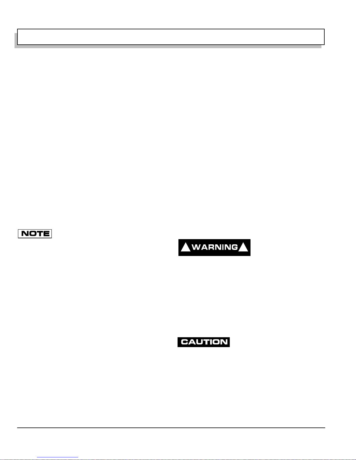
OPERATION AND SERVICE INFORMATION
Read all of manual to become thoroughly f amiliar with th is vehicle. Pay particular attention to all Notes, Cautions and Warnings
Clean windshi eld w ith lo ts of wate r and a cl ean clot h. Mi nor
scratches may be removed using a commercial plastic
polish or Plexus
parts department.
Normal cleaning of vinyl seats and plastic or rubber trim
requires the use of a mild soap solution applied with a
sponge or soft brush and wipe with a damp cloth.
Removal of oil, tar, asphalt, shoe polish, etc. will require the
use of a commercially available vinyl/rubber cleaner.
The painted surfaces of the vehicle provide attractive
appearance and durable prot ection. Frequen t washing w ith
lukewarm or cold water and mild detergent is required to
preserve the painted sur fa ces .
Occasional cleaning and waxing with non-abrasive products
designed for ‘clear coat’ automotive finishes will enhance
the appearance and durability of the painted surfaces.
Corrosive m ateria l s used as fertilizers or for dust con trol can
collect on the underbody of the v ehicl e. These materials w ill
cause corrosion of underbody parts unless flushed
occasionally w ith plain wate r. Thoroughly clean any areas
where mud or other de bris ca n collect. Sediment packed i n
closed areas should be loosened to ease it’s removal, taking
care not to chip or otherw i se damage paint.
pulling the spark plug boots, never the wires). Dry all
connections with forced air. Reinstall the wires.
®
plastic cleane r available from the se rvice
If the engine does not start or runs improperly
after wa s hi ng , r e mo ve t h e s par k p l u g wi r es (b y
VEHICLE CARE PRODUCTS
To help maintain the vehicle there are several products
available through lo cal D i stribut or s, authorized Branches , or
the Service Parts Department.
• Touch-up paint specia lly form ulated t o ma tch ve hicle
colors for use on both metal and molded plastic
bodies. (P/N 28140-G** and 28432-G**)
• Battery Protectant formulated to form a long-term,
flexible, non-tacky, dry coating that will not crack,
peel or flake over a wide temperature range. (P/N
75500-G01)
• White Lithium Grease designed to provide lubrication
protection in areas where staining or dis coloring is a
problem, or in areas of ex treme tempera ture rang es.
(P/N 75502-G01)
• Penetrant/Lu bricant, a 4-in -1 product that penet rates
seized parts, lubricates leaving a light lubricating
film, reduces corrosion by adhering to wet or dry
surfaces and displaces moisture, sealing against
future moisture ret u rn. (P/N 75503 -G01)
• Multi-purpos e Cleaner and Degrease r that contains
natural, environmen tally safe solvents. (P/N 75 504G01)
• Multi-purpos e Hand Clean er is an indus trial strengt h
cleaner contain ing no harsh solvents, y et gently lifts
grease off hands. May be used w ith or wi th out wa te r.
(P/N 75505-G01)
• Battery Cleaner that neutralizes battery acids and
dissolves termi nal corrosion and can be rins ed with
water. (P/N 75506-G01)
• Biodegradab le Cleaner that breaks down grease to
be easily wiped or rinse d aw ay. (P/N 75507-G01)
• Multi-purpos e Value Pack sampler includes 4 o unce
(118 ml) aerosol cans of Battery Protector,
Penetrant/Lubricant, White Lithium Grease, and
Carburetor and Choke Cleaner. (P/N 75508-G01)
• Plexus
®
plastic cleaner and polish removes minor
scratches from wind shi eld. (P/ N 284 33-G**)
REPAIR
LIFTING THE VEHICLE
Tool List Qty. Required
Floor jack.........................................................................1
Jack stands......................................................................4
Chocks.............................................................................4
Some servicing operations may require the front wheels, the
rear wheels, or the ent ire vehicle be raised.
To reduce the possibility of
! !
Be sure the vehicle is on a firm and level surface.
Never get under a vehicle while it is supported by a
jack.
Use jack stands and test the stability of the vehicle on
the stands.
Always place chocks in front and behind the wheels
not being raised.
Use extreme care since the vehicle is extremely
unstable during the lifting process.
When lifting vehicle, position jacks and
jack stands at the areas indicated only.
To raise the entire veh ic le , install chocks in front and behind
each front wh eel (Ref. Fig. 9 on page 7). Center the jack
under the rear frame crossmember. Raise the vehicle
enough to place a jac k stand under the outer en ds of the
rear axle.
Lower the jack and test the stability of the vehicle on the two
jack stands.
severe injury or death from
a vehicle falling from a
jack:
Page 6
Owner’s Manual and Service Guide
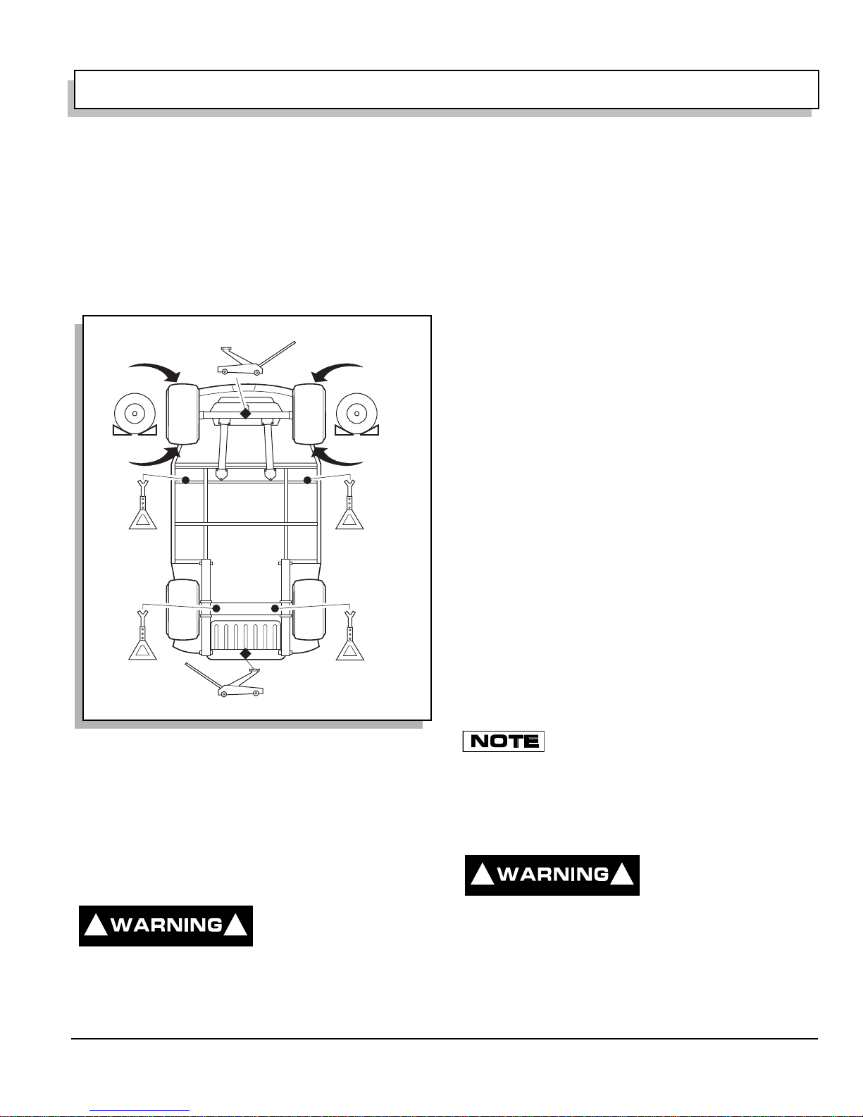
OPERATION AND SERVICE INFORMATION
R
Read all of manual to become thoroughly familiar with this vehicle. Pay part icu lar at tention to all Notes, Cautions and Warnings
Place the jack at the center of the front axle. Raise the
vehicle enough to place jack stands under the frame
crossmembe r as indicated.
Lower the jack and test the stability of t he v ehi cl e on all four
jack stands.
If only the front or rear of th e vehicle is to be raised, pl ace
the chocks in front an d behind eac h wheel not being raised
to stabilize the vehicle.
Lower the vehicle by r eversing the lifting sequence.
Center of
Front Axle
Flat Portion
of Frame
Outside End
of Rear Axle
ef Liv 1
View from Underside of Vehicle
seat beads. Due to the low volume of the small tires,
overinflation can occur i n s econds. Neve r ex ceed the
tire manufacturer’s recommendation when seating a
bead. Protect face and eyes from escaping air when
removing valve core.
To reduce the possibility of severe injury caused by a
broken socket when removing whee ls, use only
sockets designed for impact wrench use.
Use caution when inflating tires. Overinflation could
cause the tire to separate from the wheel or cause the
tire to explode, either of which could cause severe
injury.
Use caution wh en inflating tires. Du e to the low volum e of
the small tires, overinflation can occur in seconds.
Overinflation could cause the tire to separate from the wheel
or cause the tire to explod e.
Tire inflation should be de termined by the condition o f the
terrain. See GENERAL SPECIFICATIONS section for
recommended tire inflation pressure. For outdoor
applications wit h major use on grassy areas , the following
should be consi dere d. On ha rd tu rf, it is de sira ble to ha ve a
slightly highe r inflation pres sure. On very so ft turf, a lower
pressure redu ces the po ssibility of tires cutting into the tur f.
For vehicles being used on paved or hard surfaces, tire
inflation pressure sh ould be in the higher allowable range,
but under no condition should inflation pressure be higher
than recommended on tire sidewall. All four tires should
have the same pressure for optimum handling
characteristics. Be sure to install the valve dust cap after
checking or inflating.
The vehicle is fitted with low pressure tubeless tires
mounted on one piece rims; therefore, the most cost
effective way to repair a pu ncture in the tread is to use a
commercial tire plug.
Fig. 9 Lifting the Vehicle
WHEELS AND TIRES
Tire Repair
Tool List Qty. Required
Lug wrench, 3/4"..................... ....................... ..................1
Impact socket, 3/4", 1/2" drive..........................................1
Impact wrench, 1/2" drive.................................................1
Torque wrench, 1/2" drive................................................1
A tire explosion can cause
! !
sidewall.
To reduce the possibility of tire explosion, pressurize
tire with sma ll a mount o f air app lied inte rmittent ly to
severe injury or death.
Never exceed inflation
pressure rating on tire
Tire plug tools and plugs are available at most
automotive parts outlets and have the
advantage of not requiring the tire be removed from the wheel.
If the tire is flat, remove the w heel and inflate the tire to th e
maximum recommended pressure for the tire. Immerse the
tire in water to locate the leak and mark with chalk. Insert
tire plug in accordan ce w i th manufacturer’s instructions.
! !
floor. Wear OSHA appr oved safety equipment when
mounting/demounting tires.
If the tire is to be remov ed or mounted, the tire ch anging
machine manufacturer’s recommendations must be
followed in order to reduc e possibility of severe in jury.
Owner’s Manual and Service Guide
To reduce the possibility of
severe injury, be sure
mounting/demounting
machine is anchored to
Page 7
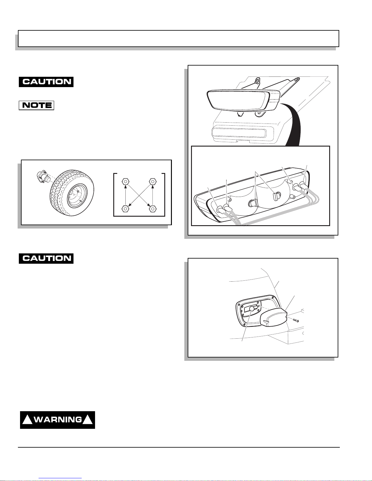
OPERATION AND SERVICE INFORMATION
R
R
Read all of manual to become thoroughly f amiliar with th is vehicle. Pay particular attention to all Notes, Cautions and Warnings
Wheel Installation
To reduce the possibility of component
damage, do not tighten lug nuts to more
than 85 ft. lbs. (115 Nm) torque.
It is important to follow the ‘cross sequence’
pattern when installing lug nuts. This will
assure even seating of the wheel against the hub.
With the valve stem to the outside, mount the wheel onto the
hub with lug nuts. Finger tighten lug nuts in a ‘cross
sequence’ patter n ( R ef . F ig. 10 on page 8). Tighten lug nu ts
to 50 - 85 ft. lbs. (70 - 115 Nm) torque in 20 ft. lbs. (30 Nm)
increments followin g th e ‘c ros s seq uence’ pattern.
Marker
'Cross Sequence'
1
3
Turn
Signal
Light
Light
Headlights
Marker
Light
Turn Signal
Light
G
R
Tire style
may vary
4
ef Whi 1
2
Fig. 10 Wheel Installati on
LIGHT BULB REPLACEMENT
To reduce the possibility of premature
bulb failure , do not touch new bulbs with
bare fingers. Use clean, dry tissue or
paper towel to handle the glass portion of the bulb.
For vehicles equipped with lights mounted below cowl,
locate bulb socket on backside of light bar (Ref. Fig. 11 on
page 8) and turn bulb socket a quarter turn
counterclockwise to unlock and pull out bulb. Insert new
bulb (Ref. Fig. 39 on page 22) and rotate socket a quarter
turn clo ckwise t o se cure.
To replace the tail and br ake light bulb, remove hard ware
securing lens and remove lens (Ref. Fig. 12 on page 8).
Install replacement bul b (Ref. Fig. 39 on page 22).
FUSE REPLACEMENT
To replace fuses, loc at e t he fuse block under the driver s id e
seat. Pull out ol d fuse and replace with a new automotive
type fuse. Headlight and taillight bulbs and fuses are
available from a loca l Distributor, an authorized Branch or
the Service Parts Department.
VEHICLE WITH A DISCHARGED BATTE RY
To reduce the possibility of
! !
severe injury or death from
inadvert ent moti on, do not
attempt to ‘jump start’ a
R
Y
Ref Hdr 1
Fig. 11 Headli ght, T urn Signal & Marker Light Bulb
Replacement
Rear
Fender
Tail Light
Lens
ef Tlr 1
Tail Light
Bulb
Fig. 12 Tail and Brake Light Bulb Replacement
vehicle.
The vehicle is equipped wi th a starter/generator and doe s
not idle. When starting the engine, the starter/generator
functions as a starter and with the engine running, it
functions as a gener at or.
With the short running times associated with this kind of
vehicle, the generator is more than adequate to maintain the
Page 8
Owner’s Manual and Service Guide
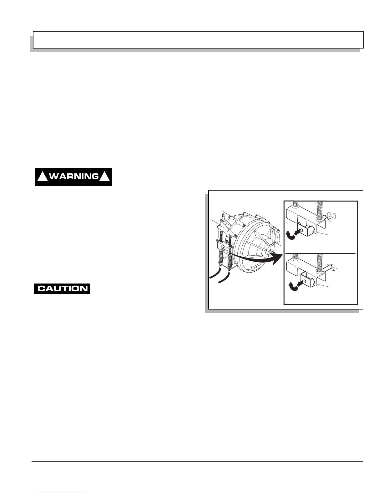
OPERATION AND SERVICE INFORMATION
Read all of manual to become thoroughly familiar with this vehicle. Pay part icu lar at tention to all Notes, Cautions and Warnings
battery charge level. The generator is not designed to
charge a discharged battery.
When engine s tarts, t he clutches engag e and cause veh ic l e
to move making ‘jump starting’ both dangerous and
impractical.
If the vehicle battery has become discharged, it must be
charged using a 12 Volt charger tha t is rated at 10 amps or
less. Read and un derstand all instructions provided by the
manufacturer of th e cha rger.
TRANSPORTING VEHICLE
TOWING
To reduce the possibility of
! !
towing a vehicle.
Do not ride on vehicle being towed.
Do not attempt to tow the vehicle with ropes, chains or
any device other than a factory approved tow bar.
Do not tow vehicle on highways.
Do not tow a single vehicle at speeds i n excess of 12
mph (19 kph).
Do not tow more than three vehicles at a time.
Do not excee d 5 mph (8 kph) while t owing multi ple
vehicles.
Place direction selector in neutral. The
neutral lock should be used to lock the
direction selector in position. This will
reduce the possibility of it moving into ‘F’ (for ward) or ‘R’ ( reverse)
while being towed, causing possible damage to the rear axle.
Do not tow a single vehicle at speeds in excess of 12 m ph (19 kph).
Do not tow more than three vehi cles at a time. Do not exceed 5 mph
(8 kph) while towing multiple vehicles. Towing the vehicle at above
recommended speed may result in severe injury and/or damage to
vehicle and other property.
Tow bars are not intended for road use.
Never use rope s or chains to tow vehi cle(s). Tow bars are
available from the Servi ce Pa rts Depart me nt .
Tow bars are not intende d for highway use. B efore towing,
place direction selec tor in neutral and eng age neutral lock.
Do not ride on vehicle being towe d. Tow bars are designed
to tow only on e vehicl e at a ma ximum speed of 12 mph (19
kph) and up to three vehicles at a maximum speed of 5 mph
(8 kph).
severe injury or death:
Use extra caution when
NEUTRAL LOCK
To prevent the driven clutch from turning the rear wheels
during service operations and to prevent wear to the belt
while being tow ed, a neutral lock is located at the dire ction
selector or the rear ax le .
On Rear Axle
To operate:
Position direction selector lever between ‘F’ and ‘R’. Turn
key switch to ‘OFF’ . Rotate pin on rear axle s hift lever as
shown (Ref. Fig. 13 on page 9). The pin will snap into a
cavity in the differential case. When in this position, the
direction select or remains loc ked in the neutr al position. To
unlock the direction se lect or, pull the pin out and rotate until
the pointed portion of the pin handle fits into the detent
position in the rear axle shift lever.
Unlocked
Position
Unlocked
Ref Nlk 1
1
2
Pull out and rotate 180
to lock
1
2
Pull out and rotate 180
to unlock
Long Tab
o
Locked
Position
Locked
Short Tab
o
Fig. 13 Neutral Lock on Rear Axle
On Direction Selector
To operate:
Turn key s w itch to ‘ OFF’ an d lift sea t. Pull o ut and rotate the
neutral lock pin handle so that the pointed portion of the
handle is to the side of the dire ction selecto r cam (Ref. Fig.
14 on page 10). Move direct ion selector towards the area
between ‘F’ and ‘R’. During that motion, the pin will snap
into the hole in the direction selector mounting bracket
preventing any movement. When in this position, the
direction select or remains loc ked in the neutr al position. To
unlock the dire ct ion selector, pull the neutral lock pi n handle
out and rotate u nt il the pointed por tion of t he handle fits into
the hole in the direction sel ector cam.
Owner’s Manual and Service Guide
Page 9
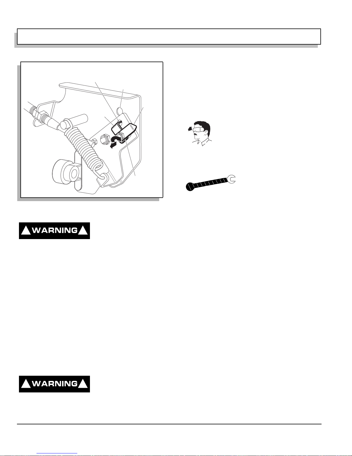
OPERATION AND SERVICE INFORMATION
k
Read all of manual to become thoroughly f amiliar with th is vehicle. Pay particular attention to all Notes, Cautions and Warnings
warnings in this manual.
Hole in Direction
Selector Cam
Unlocked
Ref Nlk 2
Fig. 14 Neutral Lock on Direction Selector
Hole in Direction
Selector Mounting
Bracket
To
Lock
2
1
Neutral Loc
Pin Handle
HAULING
To reduce the possibility of
! !
severe injury or death while
transporting vehicle:
Secure the vehicle and contents.
Never ride on vehicle being transported.
Always remove windshield before transporting.
Maximum spe ed wit h sun t op inst all ed is 50 mph ( 80
kph).
If the vehicle is to be transported at highway speeds, the
sun top must be removed and the seat bottom secured.
When transporting vehicle below highway speeds, check for
tightness of hardware and cracks in sun top at mounting
points. Always remove windshield when transporting.
Always check t hat the vehicle and contents ar e adequately
secured before transporting. The rated capacity of the trailer
or truck must exceed the weight of the vehicle (see
GENERAL SPECIFICATIONS for vehicle weight) and load.
Lock the park br ake and secure the vehicle using r at chet tie
downs.
SERVICE AND MAINTENANCE
To reduce the possibility of
! !
Do not attempt any type of ser vicin g oper atio ns be for e
reading and understanding all notes, cautions and
severe injury or death from
improper servicing
techniques:
Any servicing requiring adjustments to be made to the
powertrain while the engine is running must be made
with bot h driv e whee ls rai sed an d vehic le prop erly
supported on jack stands.
To reduce the possibility of engine damage, never
operate vehicle a t full throttle fo r more than 4 - 5
seconds while vehicle is in a ‘no load’ condition.
electrical arc, which could result in a battery
explosion, turn off all electrical loads from the battery
before removing battery wires.
explosion.
Reduce the possibili ty of accidental starting by
removing and grounding spark plug wires and
disconnecting battery at negative termina l before
servicing.
The electrolyte in a battery is an acid solution which
can cause severe burns to the skin and eyes. Treat all
electrolyte sp ills to the body and eyes wit h extende d
flushing with clear water. Conta ct a physician
immediately.
Any electrolyte spills should be neutralized with a
solution of 2 teaspoons (10 ml) sodium bicarbonate
(baking soda) dissolved in 1 quart (1 liters) of water
and flushed with water.
Aerosol containers of battery terminal protectant must
be used with extreme care. Insulate metal container to
reduce the possibility of can contac ting battery
terminals which could result in an explosion.
It is in the best interest of both vehicle o wner and service
technician, to car efull y follow the proced ures r ecom mende d
in this manual. Preventative maintenance, applied at
recommende d intervals, is the best guarantee for keeping
the vehicle both de pen dable and economical .
This vehicle will gi ve year s of sa tisfac tory ser vice, prov idin g
it receives regular maintenance. Refer to the Periodic
Service Schedul e for appropriate servic e int er vals (Ref. Fig.
17 on page 1 2). Refer to Lubrication Po ints for approp riate
lubrication locations (Ref. Fig. 36 on page 20).
Wear eye protection when working on the
vehicle. Use extra care when working
around batteries, or using solvents or
compressed air.
To reduce the poss ibility of ca using an
Wrap wrenches with vi nyl tape
to reduce the possibility of a
dropped wrench ‘shorting out’ a
battery, which could result in an
Page 10
Owner’s Manual and Service Guide
 Loading...