

Ezgo EXPRESS L6 2012, EXPRESS S6 2012 Technician's Repair And Service Manual
625610
TECHNICIAN’S REPAIR AND SERVICE MANUAL
ELECTRIC POWERED UTILITY VEHICLE
625621
REVISED AUGUST 2012 ISSUED JUNE 2012
SAFETY
WASH HANDS
AFTER HANDLING!
Battery posts,
terminals and related
accessories contain
lead and lead compounds,
chemicals known
to cause cancer and
reproductive harm.
BATTERY WARNING
WASH HANDS
AFTER HANDLING!
WARNING: Battery posts, terminals and related
accessories contain lead and lead compounds,
chemicals known to cause cancer and reproductive harm.
BATTERIES
CONTAIN LEAD
AND RELATED PARTS
!
25
DO NOT
DRIVE ACROSS
SLOPES IN
EXCESS OF 14˚
NOTICE
NOTICE
NOTICE
For any questions on material contained in this manual, contact an authorized representative for clarification.
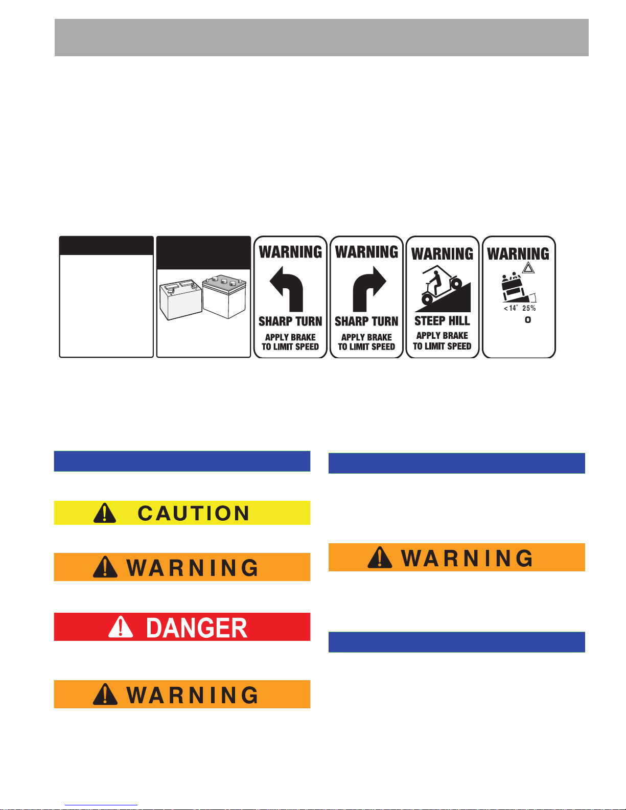
Read and understand all labels located on the vehicle. Always replace any damaged or missing labels.
On steep hills it is possible for vehicles to coast at greater than normal speeds encountered on a flat surface. To prevent loss of vehicle control and possible serious injury, speeds should be limited to no more than the maximum speed
on level ground. See GENERAL SPECIFICATIONS. Limit speed by applying the service brake.
Catastrophic damage to the drivetrain components due to excessive speed may result from driving the vehicle above
specified speed. Damage caused by excessive speed may cause a loss of vehicle control, is costly, is considered
abuse and will not be covered under warranty.
For towing/transporting vehicle, refer to “TRANSPORTING VEHICLE”.
Signs similar to the ones illustrated should be used to warn of situations that could result in an unsafe condition.
Be sure that this manual remains as part of the permanent service record should the vehicle be sold. Throughout this
guide NOTICES, CAUTION and WARNING will be used.
Observe these NOTICES, CAUTIONS and WARNINGS; be aware that servicing a vehicle requires mechanical skill
and a regard for conditions that could be hazardous. Improper service or repair may damage the vehicle or render it
unsafe.
A NOTICE indicates a condition that should be observed.
The exhaust emissions of this vehicles’ engine complies with
regulations set forth by the Environmental Protection Agency
(EPA) of the United States of America (USA) at time of manufacture. Significant fines could result from modifications or
tampering with the engine, fuel, ignition or air intake systems.
Indicates a hazardous situation which, if not avoided,
could result in minor or moderate injury.
Battery posts, terminals and related accesso-
Indicates a hazardous situation which, if not
avoided, could result in death or serious injury.
ries contain lead and lead compounds. Wash
hands after handling.
Indicates a hazardous situation which, if
not avoided, will result in death or serious
injury.
This spark ignition system meets all requirements of the
Canadian Interference-Causing Equipment Regulations.
Engine exhaust from this product contains
chemicals known, in certain quantities, to
cause cancer, birth defects, or other reproductive harm.
(NOTICES, CAUTIONS AND WARNINGS CONTINUED ON INSIDE OF BACK COVER)
Ce système d'allumage par étincelle de véhicule respecte
toutes les exigences du Règlement sur le matériel brouilleur
du Canada.

SERVICE AND REPAIR MANUAL
ELECTRIC POWERED
UTILITY VEHICLES
EXPRESS L6
EXPRESS S6
STARTING MODEL YEAR 2012
E-Z-GO Division of TEXTRON Inc. reserves the right to incorporate engineering and design changes to products in this Manual, without obligation to
include these changes on units leased/sold previously.
The information contained in this Manual may be revised periodically by E-Z-GO, and therefore is subject to change without notice.
E-Z-GO DISCLAIMS LIABILITY FOR ERRORS IN THIS MANUAL, and E-Z-GO SPECIFICALLY DISCLAIMS LIABILITY FOR INCIDENTAL AND CON-
SEQUENTIAL DAMAGES resulting from the use of the information and materials in this Manual.
TO CONTACT US
NORTH AMERICA:
TECHNICAL ASSISTANCE & WARRANTY PHONE: 1-800-774-3946, FAX: 1-800-448-8124
SERVICE PARTS PHONE: 1-888-GET-EZGO (1-888-438-3946), FAX: 1-800-752-6175
INTERNATIONAL: PHONE: 001-706-798-4311, FAX: 001-706-771-4609
Repair and Service Manual
Page i

GENERAL INFORMATION
This vehicle has been designed and manufactured in the United States of America (USA) as
a ‘World Vehicle’. The Standards and Specifications listed in the following text originate in
the USA unless otherwise indicated.
The use of non Original Equipment Manufacturer (OEM) approved parts may void the
warranty.
Tampering with or adjusting the governor to permit vehicle to operate at above factory
specifications will void the vehicle warranty.
When servicing engines, all adjustments and replacement components must be per original
vehicle specifications in order to maintain the United States of America Federal and State
emission certification applicable at the time of manufacture.
BATTERY PROLONGED STORAGE
All batteries will self discharge over time. The rate of self discharge varies depending on the
ambient temperature and the age and condition of the batteries.
A fully charged battery will not freeze in winter temperatures unless the temperature falls
below -75° F (-60° C).
BATTERY DISPOSAL
Lead-acid batteries are recyclable. Return whole scrap batteries to distributor, manufacturer
or lead smelter for recycling. For neutralized spills, place residue in acid-resistant
containers with absorbent material, sand or earth and dispose of in accordance with local,
state and federal regulations for acid and lead compounds. Contact local and/or state
environmental officials regarding disposal information.
Page ii
Repair and Service Manual

TABLE OF CONTENTS
TITLE PAGE
SAFETY .......................................................................................................................Inside Covers
GENERAL INFORMATION...............................................................................................................ii
SAFETY INFORMATION ................................................................................................................. v
TITLE SECTION
GENERAL INFORMATION & ROUTINE MAINTENANCE ..............................................................A
SAFETY ...........................................................................................................................................B
BODY...............................................................................................................................................C
WHEELS AND TIRES......................................................................................................................D
FRONT SUSPENSION AND STEERING ........................................................................................E
ELECTRONIC SPEED CONTROL ..................................................................................................F
MOTOR........................................................................................................................................... G
BATTERIES AND CHARGING.........................................................................................................H
BATTERY CHARGER...................................................................................................................... J
BRAKES...........................................................................................................................................K
ELECTRICAL SYSTEM ................................................................................................................... L
REAR SUSPENSION......................................................................................................................M
REAR AXLE......................................................................................................................
WEATHER PROTECTION...............................................................................................................P
HANDHELD DEVICE...................................................................................................................... Q
TROUBLESHOOTING.....................................................................................................................R
LIGHTING PROTECTION AND GROUNDING................................................................................S
GENERAL SPECIFICATIONS .........................................................................................................T
...............N
Repair and Service Manual
Page iii

NOTES:
TABLE OF CONTENTS
Page iv
Repair and Service Manual

SAFETY INFORMATION
Read all of Section B and this section before attempting any procedure. Pay particular attention to Notices, Cautions, Warnings and Dangers.
This manual has been designed to assist the owner-operator in maintaining the vehicle in accordance with
procedures developed by the manufacturer. Adherence to these procedures and troubleshooting tips will ensure the
best possible service from the product. To reduce the chance of personal injury and/or property damage, the
following instructions must be carefully observed:
GENERAL
Many vehicles are used for a variety of tasks beyond the original intended use of the vehicle; therefore it is impossible
to anticipate and warn against every possible combination of circumstances that may occur. No warnings can take
the place of good common sense and prudent driving practices.
Good common sense and prudent driving practices do more to prevent accidents and injury than all of the warnings
and instructions combined. The manufacturer strongly suggests that the owner-operator read this entire manual
paying particular attention to the CAUTIONS and WARNINGS contained therein. It is further recommended that
employees and other operators be encouraged to do the same.
If you have any questions, contact your closest representative or write to the address on the back cover of this
publication, Attention: Customer Care Department.
E-Z-GO Division of Textron reserves the right to make design changes without obligation to make these changes on
units previously sold and the information contained in this manual is subject to change without notice.
E-Z-GO Division of Textron is not liable for errors in this manual or for incidental or consequential damages that result
from the use of the material in this manual.
This vehicle conforms to the current applicable standard for safety and performance requirements.
These vehicles are designed and manufactured for off-road use. They do not conform to Federal Motor Vehicle
Safety Standards and are not equipped for operation on public streets. Some communities may permit these vehicles
to be operated on their streets on a limited basis and in accordance with local ordinances.
With electric powered vehicles, be sure that all electrical accessories are grounded directly to the battery (-) post.
Never use the chassis or body as a ground connection.
Refer to GENERAL SPECIFICATIONS for vehicle seating capacity.
Never modify the vehicle in any way that will alter the weight distribution of the vehicle, decrease
its stability, increase the speed or extend the stopping distance beyond the factory specification.
Such modifications can result in serious personal injury or death.
Modifications that increase the speed and/or weight of the vehicle will extend the stopping distance and may reduce
the stability of the vehicle. Do not make any such modifications or changes. The manufacturer prohibits and disclaims responsibility for any such modifications or any other alteration which would adversely affect the safety of the
vehicle.
Vehicles that are capable of higher speeds must limit their speed to no more than the speed of other vehicles when
used in a golf course environment. Additionally, speed should be further moderated by the environmental conditions,
terrain and common sense.
Repair and Service Manual
Page v

SAFETY INFORMATION
Read all of Section B and this section before attempting any procedure. Pay particular attention to Notices, Cautions, Warnings and Dangers.
GENERAL OPERATION
B
ALWAYS:
use the vehicle in a responsible manner and maintain the vehicle in safe operating condition.
read and observe all warnings and operation instruction labels affixed to the vehicle.
follow all safety rules established in the area where the vehicle is being operated.
reduce speed to compensate for poor terrain or conditions.
apply service brake to control speed on steep grades.
maintain adequate distance between vehicles.
reduce speed in wet areas.
use extreme caution when approaching sharp or blind turns.
use extreme caution when driving over loose terrain.
use extreme caution in areas where pedestrians are present.
MAINTENANCE
ALWAYS:
maintain your vehicle in accordance with the manufacturer’s periodic service schedule.
ensure that mechanics performing repairs are trained and qualified to do so.
follow the manufacturer’s directions if you do any maintenance on your vehicle. Be sure to disable the vehicle before
performing any maintenance. Disabling includes removing the key from the key switch and removal of a battery wire.
insulate any tools used within the battery area in order to prevent sparks or battery explosion caused by shorting the
battery terminals or associated wiring. Remove the batteries or cover exposed terminals with an insulating material.
check the polarity of each battery terminal and be sure to rewire the batteries correctly.
use specified replacement parts. Never use replacement parts of lesser quality.
use recommended tools.
determine that tools and procedures not specifically recommended by the manufacturer will not compromise the safety
of personnel nor jeopardize the safe operation of the vehicle.
support the vehicle using wheel chocks and safety stands. Never get under a vehicle that is supported by a jack. Lift
the vehicle in accordance with the manufacturer’s instructions.
Never attempt to maintain a vehicle in an area where exposed flame is present or persons are smoking.
be aware that a vehicle that is not performing as designed is a potential hazard and must not be operated.
The manufacturer cannot anticipate all situations, therefore people attempting to maintain or repair the vehicle must
have the skill and experience to recognize and protect themselves from potential situations that could result in severe
personal injury or death and damage to the vehicle. Use extreme caution and, if unsure as to the potential for injury,
refer the repair or maintenance to a qualified mechanic.
Page vi
Repair and Service Manual

SAFETY INFORMATION
Read all of Section B and this section before attempting any procedure. Pay particular attention to Notices, Cautions, Warnings and Dangers.
B
ALWAYS:
test drive the vehicle after any repairs or maintenance. All tests must be conducted in a safe area that is free of both
vehicular and pedestrian traffic.
replace damaged or missing warning, caution or information labels.
keep complete records of the maintenance history of the vehicle.
VENTILATION
Hydrogen gas is generated in the charging cycle of batteries and is explosive in concentrations as low as 4%.
Because hydrogen gas is lighter than air, it will collect in the ceiling of buildings necessitating proper ventilation. Five
air exchanges per hour is considered the minimum requirement.
Never charge a vehicle in an area that is subject to flame or spark. Pay particular attention to natural gas or propane
gas water heaters and furnaces.
Use a dedicated circuit for each battery charger. Do not permit other appliances to be plugged into the receptacle
when the charger is in operation.
Chargers must be installed and operated in accordance with charger manufacturers recommendations or applicable
electrical code (whichever is more restrictive).
B
Repair and Service Manual
Page vii

SAFETY INFORMATION
Read all of Section B and this section before attempting any procedure. Pay particular attention to Notices, Cautions, Warnings and Dangers.
Notes:
Page viii
Repair and Service Manual

GENERAL INFORMATION & ROUTINE MAINTANENCE
TABLE OF CONTENTS FOR SECTION ‘A’
SECTION TITLE PAGE NO.
SERIAL NUMBER LOCATION ................................................................................. A - 1
TRANSPORTING VEHICLE ..................................................................................... A - 1
Towing ............................................................................................................. A - 1
Hauling ............................................................................................................. A - 1
SERVICING THE ELECTRIC VEHICLE.................................................................... A - 1
ROUTINE MAINTENANCE ...................................................................................... A - 2
REAR AXLE.............................................................................................................. A - 2
BRAKES ................................................................................................................... A - 2
TIRES........................................................................................................................ A - 2
LIGHT BULB REPLACEMENT ................................................................................. A - 2
VEHICLE CLEANING AND CARE ............................................................................ A - 2
VEHICLE CARE PRODUCTS ................................................................................... A - 3
SUN TOP AND WINDSHIELD .................................................................................. A - 3
HARDWARE ............................................................................................................. A - 4
TORQUE SPECIFICATIONS .................................................................................... A - 4
PERIODIC SERVICE SCHEDULE ............................................................................ A - 5
LIST OF ILLUSTRATIONS
Fig. 1 Initial Service Chart ..................................................................................... A - 2
Fig. 2 Lubrication Points ........................................................................................ A - 2
Fig. 3 Torque Specifications .................................................................................. A - 4
Fig. 4 Periodic Service Schedule ........................................................................... A - 5
Repair and Service Manual
Page A-i

GENERAL INFORMATION & ROUTINE MAINTANENCE
Read all of Section B and this section before attempting any procedure. Pay particular attention to Notices, Cautions, Warnings and Dangers
Notes:
Page A-ii
Repair and Service Manual
GENERAL INFORMATION & ROUTINE MAINTANENCE
Read all of Section B and this section before attempting any procedure. Pay particular attention to Notices, Cautions, Warnings and Dangers.
SERIAL NUMBER LABEL
LOCATION
Two serial number and manufacture date code label are
on the vehicle. One is placed on the body below the
front, driver side of the seat. The other is located on the
chassis under the seat.
Design changes take place on an ongoing basis. In
order to obtain correct components for the vehicle, the
manufacture date code, serial number and vehicle
model must be provided when ordering service parts.
TRANSPORTING VEHICLE
Towing
This vehicle is not designed to be towed.
It is recommended that the vehicle be moved by placing
the entire vehicle on a trailer, flatbed truck or other
suitable transport.
Hauling
To reduce the possibility of severe injury or
death while transporting vehicle:
Secure the vehicle and contents.
Never ride on vehicle being transported.
Always remove windshield before
transporting.
Maximum speed with sun top installed is
50 mph (80 kph).
If the vehicle is to be transported at highway speeds,
the sun top must be removed and the seat bottom
secured. When transporting vehicle below highway
speeds, check for tightness of hardware and cracks in
sun top at mounting points. Always remove windshield
when transporting. Always check that the vehicle and
contents are adequately secured before transporting.
The rated capacity of the trailer or truck must exceed
the weight of the vehicle (see GENERAL SPECIFICATIONS for vehicle weight) and load plus 1000 lbs. (454
kg). Lock the park brake and secure the vehicle using
ratchet tie downs.
SERVICING THE ELECTRIC
VEHICLE
To prevent severe injury or death, resulting
from improper servicing techniques, observe
the following Warnings:
Do not attempt any type of servicing operations before reading and understanding all
notes, cautions and warnings in
this manual.
Any servicing requiring adjustments to be
made to the powertrain while the motor is
running must be made with both drive
wheels raised.
Wear eye protection when working on the vehicle. In particular,
use care when working around
batteries, or using solvents or
compressed air.
To reduce the possibility of causing an
electrical arc, which could result in a battery explosion, turn off all electrical loads
from the batteries before removing any
heavy gauge battery wires.
To prevent the possibility of motor
disintegration, never operate vehicle at full
throttle for more than 4 - 5 seconds while
vehicle is in a “no load” condition.
It is in the best interest of both vehicle owner and servicing dealer to carefully follow the procedures recommended in this manual. Adequate preventive
maintenance, applied at regular intervals, is the best
guarantee for keeping the vehicle both dependable and
economical.
Before a new vehicle is put into operation, it is recommended that the items shown in the INITIAL SERVICE
CHART be performed (Ref. Fig. 1).
Vehicle batteries must be fully charged before initial
use.
Repair and Service Manual
Page A-1
GENERAL INFORMATION & ROUTINE MAINTANENCE
ITEM SERVICE OPERATION
Batteries Charge batteries
Seats Remove protective plastic covering
Brakes Check operation and adjust if necessary
Establish acceptable stopping distance
Check hydraulic brake fluid level
Tires Check air pressure (see SPECIFICATIONS)
Portable Remove from vehicle and properly mount
Charger
NOTICE
Rack
Ball
Joint
Read all of Section B and this section before attempting any procedure. Pay particular attention to Notices, Cautions, Warnings and Dangers.
REAR AXLE
B
The only maintenance required for the first five years is
the periodic inspection of the lubricant level. The rear
axle is provided with a lubricant level check/fill plug
located on the bottom of the differential. Unless leakage
is evident, the lubricant need to be only replaced after
five years. The procedure to follow for checking the rear
axle lubricant level is in the REAR AXLE section.
BRAKES
After the vehicle has been put into service, it is recom-
Fig. 1 Initial Service Chart
ROUTINE MAINTENANCE
mended that the brakes be checked daily by performing
a brake test.
Some maintenance items must be serviced more frequently on
vehicles used under severe driving conditions.
This vehicle will give years of satisfactory service
provided it receives regular maintenance. Refer to the
Periodic Service Schedule for appropriate service intervals (Ref. Fig. 4). Refer to Lubrication Point for
appropriate lubrication location (Ref. Fig. 2).
Fig. 2 Lubrication Points
Do not use more than three pumps of grease for each
grease fitting at any one time- Excess grease may
cause grease seals to fail or grease migration into
areas that could damage components.
To prevent severe injury or death resulting
from operating a vehicle with improperly operating brake system, the braking system must
be properly maintained. All driving brake tests
must be done in a safe location with regard for
the safety of all personnel.
For information on conducting a brake test, refer to
BRAKES section.
TIRES
Tire condition should be inspected per the Periodic
Service Schedule. Inflation pressures should be
checked when the tires are cool. Be sure to reinstall
valve dust cap after checking or inflating. For additional
information, refer to WHEELS AND TIRES section.
LIGHT BULB REPLACEMENT
Refer to ELECTRICAL SYSTEM for information regarding light bulb replacement.
VEHICLE CLEANING AND CARE
Putting more than three pumps of grease in a grease fitting could damage grease seals and cause premature
bearing failure.
Page A-2
When pressure washing vehicle, do not use pressure in
excess of 700 psi (4826 kPa). To prevent cosmetic
damage, do not use any abrasive or reactive solvents
to clean plastic parts.
It is important that proper techniques and cleaning
materials be used. Using excessive water pressure may
Repair and Service Manual

GENERAL INFORMATION & ROUTINE MAINTANENCE
Read all of Section B and this section before attempting any procedure. Pay particular attention to Notices, Cautions, Warnings and Dangers.
cause damage to seals, plastics, the electrical system,
body finish or seat material. Do not use pressure in
excess of 700 psi (4826 kPa) to wash vehicle.
Normal cleaning of vinyl seats and plastic or rubber trim
require the use of a mild soap solution applied with a
sponge or soft brush and wipe with a damp cloth.
Removal of oil, tar, asphalt, shoe polish, etc. will require
the use of a commercially available vinyl/rubber cleaner.
The painted surfaces of the vehicle provide attractive
appearance and durable protection. Frequent washing
with lukewarm or cold water is the best method of
preserving those painted surfaces.
Do not use hot water, strong soap or harsh chemical
detergents.
Rubber parts should be cleaned with non-abrasive
household cleaner.
Occasional cleaning and waxing with non-abrasive
products designed for ‘clear coat’ automotive finishes
will enhance the appearance and durability of the
painted surfaces.
Corrosive materials used as fertilizers or for dust control
can collect on the underbody of the vehicle. These
materials will accelerate corrosion of underbody parts. It
is recommended that the underbody be flushed occasionally with plain water. Thoroughly clean any areas
where mud or other debris can collect. Sediment packed
in closed areas should be loosened to ease its removal,
taking care not to chip or otherwise damage paint.
SUN TOP AND WINDSHIELD
B
The sun top does not provide protection from
roll over or falling objects.
The windshield does not provide Complete
protection from tree limbs or flying objects.
The sun top and windshield are designed for weather
protection only.
Clean with lots of water and a clean cloth. Minor
scratches may be removed using a commercial plastic
polish or Plexus plastic cleaner available from Service
Parts Department.
VEHICLE CARE PRODUCTS
To help maintain the vehicle, there are several products
available through local Distributors, authorized
Branches, or the Service Parts Department.
• Touch-up paint specially formulated to match
vehicle colors for use on TPE (plastic) bodies
(P/N 28140-G** and 28432G**).
• Multi-purpose Battery Protectant formulated to
form a long-term, flexible, non-tacky, dry coating
that will not crack, peel or flake over a wide
temperature range (P/N 606312).
• Multi-purpose Hand Cleaner is an industrial
strength cleaner containing no harsh solvents, yet
gently lifts grease off hands. May be used with or
without water (P/N 607636).
• Battery Maintenance Kit for complete battery
cleaning and watering, with battery maintenance
instructions (P/N 25587G01).
• Plexus plastic cleaner and polish removes minor
scratches from windshield (P/N 606314).
Repair and Service Manual
Page A-3
GENERAL INFORMATION & ROUTINE MAINTANENCE
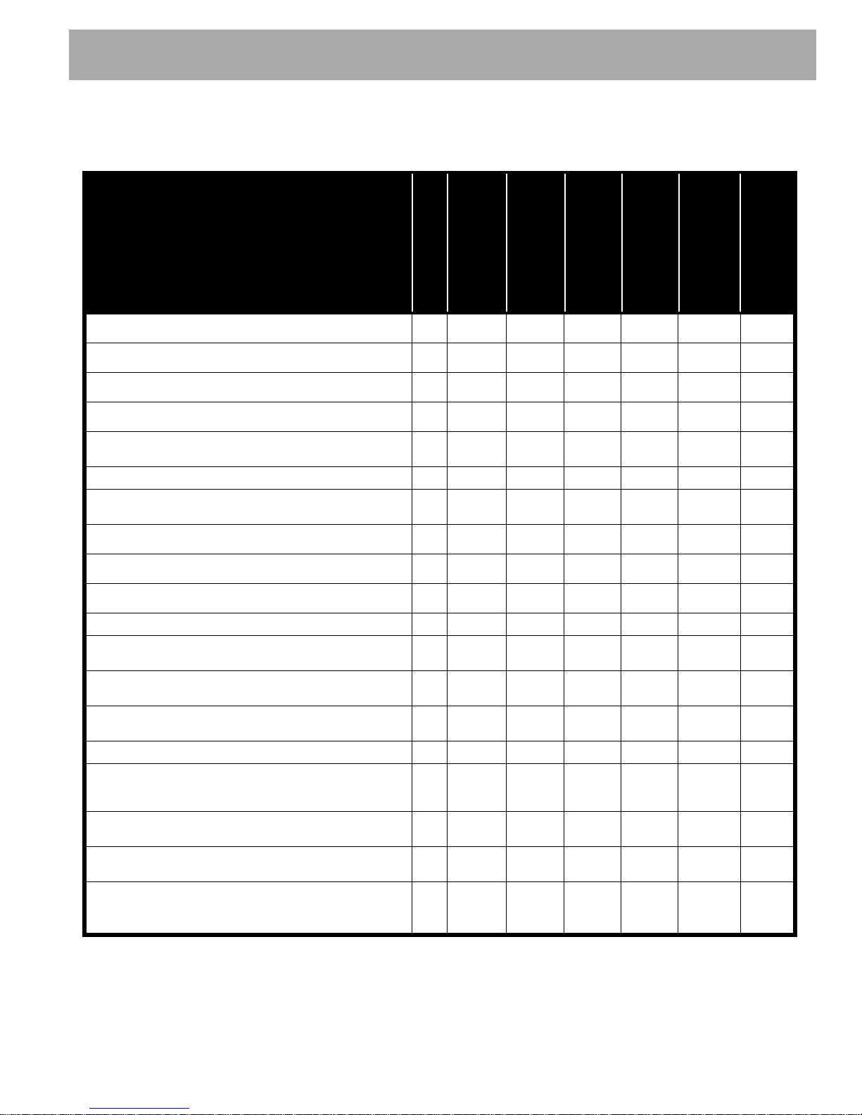
ALL TORQUE FIGURES ARE IN FT. LBS. (Nm)
BOLT SIZE
Grade 2
1/4" 5/16" 3/8" 7/16" 1/2" 9/16" 5/8" 3/4" 7/8" 1"
Unless otherwise noted in text, tighten all hardware in accordance with this chart.
This chart specifies 'lubricated' torque figures. Fasteners that are plated or lubricated when
installed are considered 'wet' and require approximately 80% of the torque required for 'dry' fasteners.
4
(5)
8
(11)
15
(20)
24
(33)
35
(47)
55
(75)
75
(102)
130
(176)
125
(169)
190
(258)
Grade 5
Grade 8
6
(8)
13
(18)
23
(31)
35
(47)
55
(75)
80
(108)
110
(149)
200
(271)
320
(434)
480
(651)
6
(8)
18
(24)
35
(47)
55
(75)
80
(108)
110
(149)
170
(230)
280
(380)
460
(624)
680
(922)
BOLT SIZE
Class 5.8
(Grade 2)
M4 M5 M6 M8 M10 M12 M14
1
(2)
2
(3)
4
(6)
10
(14)
20
(27)
35
(47)
55
(76.4)
Class 8.8
(Grade 5)
2
(3)
4
(6)
7
(10)
18
(24)
35
(47)
61
(83)
97
(131)
Class 10.9
(Grade 8)
3
(4)
6
(8)
10
(14)
25
(34)
49
(66)
86
(117)
136
(184)
5.8
8.8
10.9
Read all of Section B and this section before attempting any procedure. Pay particular attention to Notices, Cautions, Warnings and Dangers.
HARDWARE
B
Periodically the vehicle should be inspected for loose
fasteners. Fasteners should be tightened in accordance
with the Torque Specifications table (Ref. Fig. 3).
Use care when tightening fasteners and refer to the
Technician’s Repair and Service Manual for specific
torque values.
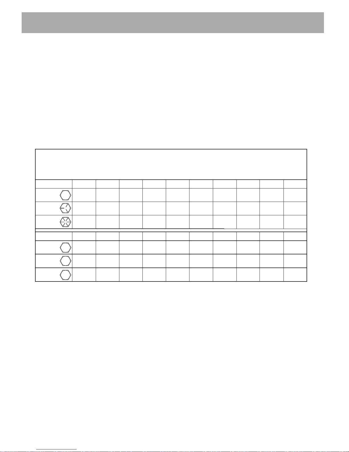
TORQUE SPECIFICATIONS
Generally, two grades of hardware are used in the
vehicle.
• Grade 5 hardware can be identified by the three
marks on the hexagonal head.
• Unmarked hardware is Grade 2.
Page A-4
Fig. 3 Torque Specifications
Repair and Service Manual
GENERAL INFORMATION & ROUTINE MAINTANENCE
Read all of Section B and this section before attempting any procedure. Pay particular attention to Notices, Cautions, Warnings and Dangers.
PERIODIC SERVICE SCHEDULE
- CHECK C&A - CHECK & ADJUST CL - CLEAN R - REPLACE
REMARKS
20 rnds/20 hrs
100 miles/160 kms
before each use
DAILY
Tires - pressure, condition of tires & rims
Hardwares and Fasteners - loose or missing
Reverse Warning Indicator
Overall Vehicle Condition
Batteries - state of charge, condition, loose terminals,
corrosion, hold down & hardware
Batteries* - check electrolyte level, fill if required C&A C&A C&A C&A
Brakes - smooth operation of pedal, Fluid , stopping
distance
Brakes - aggressive stop test, does brake hold on a hill
MONTHLY
60 rnds/60 hrs
300 miles/500 kms
QUARTERLY
125 rnds/125 hrs
600miles/1000 kms
SEMI-ANNUAL
CL CL CL CL
B
250 rnds/250 hrs
1200miles/2000 kms
ANNUAL
5 YEARS
PAGE
Accelerator - smooth operation
Wiring - loose connections, broken or missing insulation
Charger Receptacle - clean connections CL CL CL CL
Steering Assembly - excessive play, loose or missing
hardware
Tie Rods - excessive play, bent rods, loose or missing
hardware
Rear Axle - oil leakage, noise, loose or missing
hardware
Rear Axle - drain & replace fluid R
Front Suspension - strut oil leakage, excessive play in
hubs or kingpins, worn bushings, loose or missing
hardware
Front Wheel Alignment - unusual tire wear, missing lug
nuts.
Rear Suspension - shock oil leakage, worn bushings,
loose or missing hardware
Motor Coupling - Add Anti - Sieze compound
(Apporx 1 tablespoon)
Fig. 4 Periodic Service Schedule
C&A C&A C&A
20,000
AMPHrs
*Use only distilled or purified water that is free of contaminants to fill batteries.
Repair and Service Manual
Page A-5

GENERAL INFORMATION & ROUTINE MAINTANENCE
Read all of Section B and this section before attempting any procedure. Pay particular attention to Notices, Cautions, Warnings and Dangers.
Notes:
Page A-6
Repair and Service Manual

SAFETY
TABLE OF CONTENTS FOR SECTION ‘B’
SECTION TITLE PAGE NO.
NOTICES, CAUTIONS WARNINGS AND DANGERS..............................................B - 1
IMPORTANT SAFETY WARNING ............................................................................B - 1
MODIFICATIONS TO VEHICLE ................................................................................B - 1
GENERAL MAINTENANCE ......................................................................................B - 1
BEFORE SERVICING THE VEHICLE .......................................................................B - 1
Additional Warnings.......................................................................................... B - 2
BATTERY REMOVAL & INSTALLATION .................................................................B - 3
LIFTING THE VEHICLE ............................................................................................B - 4
LIST OF ILLUSTRATIONS
Fig. 1 Battery Connections ....................................................................................B - 3
Fig. 2 Lifting the Vehicle .......................................................................................B - 4
Repair and Service Manual
Page B-i

SAFETY
Read all of Section B and this section before attempting any procedure. Pay particular attention to Notices, Cautions, Warnings and Dangers.
Notes:
Page B-ii
Repair and Service Manual
SAFETY
NOTICE
DANGER
Read all of Section B and this section before attempting any procedure. Pay particular attention to Notices, Cautions, Warnings and Dangers.
B
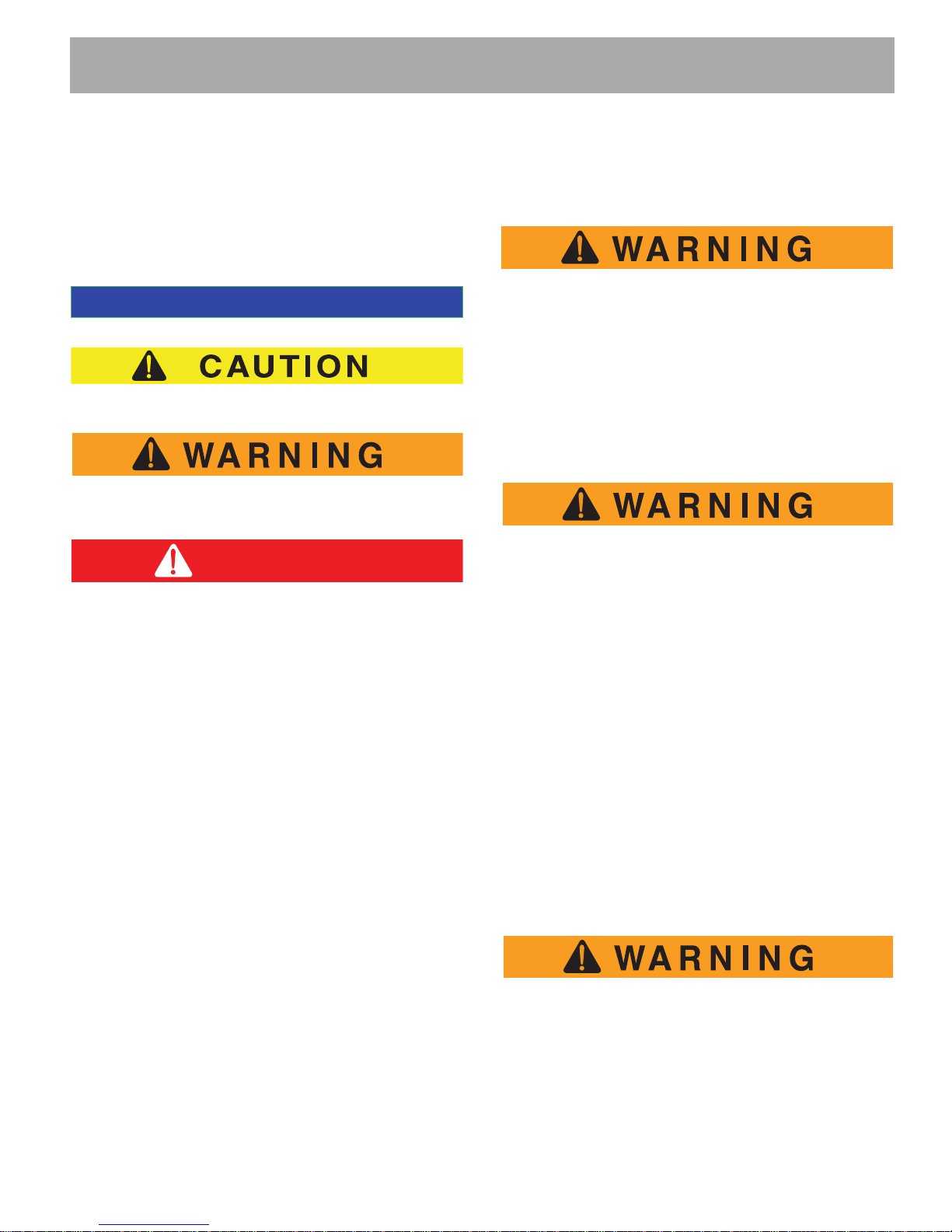
NOTICES, CAUTIONS, WARNINGS
AND DANGERS
Throughout this manual, the following NOTICES,
CAUTIONS, WARNINGS and DANGERS are used. For
the protection of all personnel and the vehicle, be aware
of and observe the following:
A NOTICE indicates a condition that should be observed.
A CAUTION indicates a condition that may result in
damage to the vehicle or surrounding facilities.
A WARNING indicates a hazardous condition
which could result in serious injury or death.
Indicates a hazardous situation which, if
not avoided, will result in death or serious
injury.
IMPORTANT SAFETY WARNING
Always use the appropriate tools listed in the tool list
and wear approved safety equipment.
MODIFICATIONS TO VEHICLE
To prevent personal injury or death to the
operator or passenger(s), do not make
changes to the weight distribution or the
center of gravity which could make the vehicle
unstable or prone to roll over.
Do not modify the vehicle in any manner that will change
the weight distribution of the vehicle.
GENERAL MAINTENANCE
To prevent severe injury or death resulting
from improper servicing techniques, observe
the following Warnings:
Do not attempt any type of servicing
operations before reading and understanding
all notes, cautions and warnings in this
manual.
B
In any product, components will eventually fail to
perform properly as the result of normal use, age, wear
or abuse. It is virtually impossible to anticipate all
possible component failures or the manner in which
each component may fail.
Be aware that a vehicle requiring repair indicates that
the vehicle is no longer functioning as designed and
therefore should be considered potentially hazardous.
Use extreme care when working on any vehicle. When
diagnosing, removing or replacing any components that
are not operating correctly, take the time to consider the
safety of yourself and others around you if the
component should move unexpectedly.
Some components are heavy, spring loaded, highly
corrosive, explosive or may produce high amperage or
reach high temperatures. Battery acid and hydrogen gas
could result in serious bodily injury to the technician/
mechanic and bystanders if not treated with utmost
caution. Be careful not to place hands, face, feet or
body in a location that could expose them to injury
should an unforeseen situation occur.
When any maintenance procedure or inspection is
performed, it is important that care be exercised to
insure the safety of the technician/mechanic or
bystanders and to prevent damage to the vehicle.
Always read and understand the entire relevant manual
section (chapter) before attempting any inspection or
service.
BEFORE SERVICING THE VEHICLE
Before attempting to inspect or service a vehicle, be
sure to read and understand the following warnings:
To prevent personal injury or death, observe
the following:
Before working on vehicle, remove all
jewelry (watches, rings, etc.).
Be sure that no loose clothing or hair can
Repair and Service Manual
Page B-1
SAFETY
Read all of Section B and this section before attempting any procedure. Pay particular attention to Notices, Cautions, Warnings and Dangers.
become caught in the moving parts of the
B
powertrain.
Use care not to contact hot objects.
Any servicing requiring adjustments to be
made to the powertrain while the motor is
running must be made with both wheels
raised.
To prevent the possibility of motor
disintegration, never operate vehicle at full
throttle for more than 4 - 5 seconds while
vehicle is in a “no load” condition.
Wear OSHA approved clothing and eye
protection when working on anything that
could expose the body or eyes to potential
injury. In particular, use care when working
with or around batteries, compressed air or
solvents.
Always turn the key switch to ‘OFF’ and
remove the key before disconnecting a live
circuit.
When connecting battery cables, pay particular attention to the polarity of the battery
terminals. Never confuse the positive and
negative cables.
The parking ‘PARK’ brake should always
be set, except for cases where the powertrain must be allowed to rotate or service is
being performed on the brake system.
If repairs are to be made that will require
welding or cutting, the batteries must be
removed.
Additional Warnings
Before working on the electrical system, be sure to read
and understand the following warnings that pertain to
electrical system repair or maintenance.
To prevent battery explosion that could result
in severe personal injury or death, keep all
smoking materials, open flame or sparks away
from the batteries.
Hydrogen gas is generated in the charging
cycle of batteries and is explosive in
concentrations as low as 4%. Because
hydrogen gas is lighter than air, it will
collect in the ceiling of buildings
necessitating proper ventilation. Five air
exchanges per hour is considered the
minimum requirement.
Be sure that the key switch is off and all
electrical accessories are turned off before
starting work on vehicle.
Batteries should always be removed before
any servicing or repairs that could generate
sparks.
Never disconnect a circuit under load at a
battery terminal.
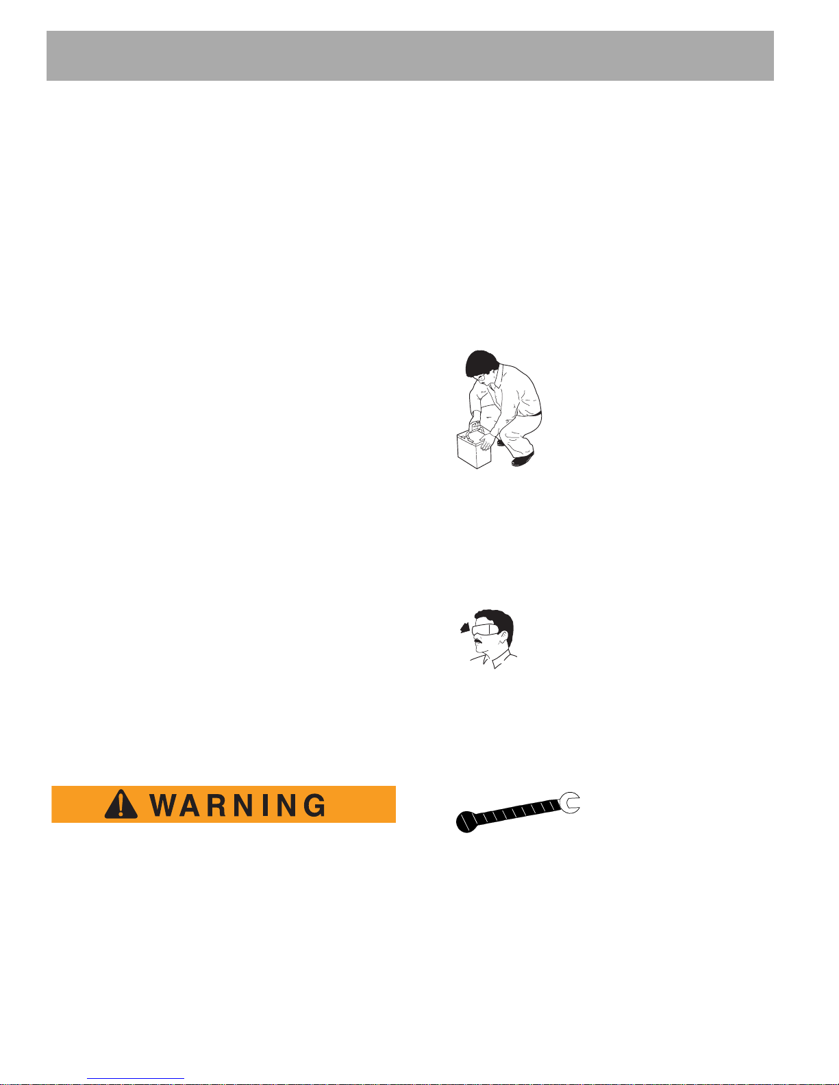
Batteries are heavy. Use
proper lifting techniques when
moving them. Always lift the
battery with a commercially
available battery lifting device.
Use care not to tip batteries
when removing or installing
them; spilled electrolyte can
cause burns and damage.
The electrolyte in a storage battery is an
acid solution which can cause severe burns
to the skin and eyes. Treat all electrolyte
spills to the body and eyes with extended
flushing with clear water. Contact a
physician immediately.
Wear eye protection when
working on the vehicle. In particular, use care when working
around batteries, or using
solvents or compressed air.
Any electrolyte spills should be neutralized
with a solution of 1/4 cup (60 ml) sodium
bicarbonate (baking soda) dissolved in
1 1/2 gallons (6 liters) of water and flushed
with water.
Wrap wrenches with
vinyl tape to prevent the
possibility of a dropped
wrench from ‘shorting
out’ a battery, which could result in an
explosion and severe personal injury or
death.
Aerosol containers of battery terminal
protectant must be used with extreme
care. Insulate metal container to prevent
can from contacting battery terminals which
could result in an explosion.
Page B-2
Repair and Service Manual

SAFETY
NOTICE
+
-
+
-
+
-
+
-
+
-
+
-
Front of Vehicle
BL+ to
Solenoid
+
-
+
-
To
Charger
BL- to Bon ESC
Read all of Section B and this section before attempting any procedure. Pay particular attention to Notices, Cautions, Warnings and Dangers.
should be present. If any corrosion is found, it should be
immediately removed with a putty knife and wire brush.
The area should be washed with a solution of sodium
bicarbonate (baking soda) and water and thoroughly
Overfilling batteries may result in electrolyte being
expelled from the battery during the charge cycle.
Expelled electrolyte may cause damage to the vehicle
and storage facility.
BATTERY REMOVAL &
INSTALLATION
Tool List Qty.
Insulated wrench, 1/2" ................................................. 1
Socket, 1/2" ................................................................. 1
Ratchet ........................................................................ 1
Battery carrier.............................................................. 1
Torque wrench (in. lbs.)............................................... 1
In the following text, there are references to removing/installing
bolts etc. Additional hardware (nuts, washers etc.) that are
removed must always be installed in its original position unless
otherwise specified. Nonspecified torques are as shown in
table contained in Section “A”.
Before any electrical service is performed on PDS model
vehicles, the Run-Tow/Maintenance switch must be
placed in the ‘Tow/Maintenance’ position.
dried before priming and painting with a corrosion
resistant paint.
Place batteries into the battery rack. Install the battery
hold downs and tighten to 45 - 55 in. lbs. (5 - 6 Nm)
torque, to prevent movement but not tight enough to
cause distortion of the battery cases.
Inspect all wires and terminals and clean any corrosion
from the battery terminals or the wire terminals with a
solution of sodium bicarbonate (baking soda) and wire
brush if required.
Aerosol containers of battery terminal
protectant must be used with extreme care.
Insulate metal container to prevent can from
contacting battery terminals which could result
in an explosion.
Use care to connect battery cables as shown in the
following illustration (Ref. Fig. 1). Connect the positive
(+) battery cable first, other battery connecting cables,
and then connect the negative (-) cable last. Ensure
that all battery terminals are installed with crimp up.
Tighten the battery post hardware to 90 - 100 in. lbs.
(10 - 11 Nm). Protect the battery terminals and battery
cable terminals with a commercially available
protective coating.
B
B
If a power wire (battery, motor or controller) is disconnected for any reason on the PDS model vehicle, the
Run-Tow/Maintenance switch must be left in the ‘Tow/
Maintenance’ position for at least 30 seconds after the
circuit is restored.
Turn vehicle key to ‘OFF’ and remove. Insure all optional
electrical accessories are turned OFF.
Using an insulated wrench, remove the negative (-)
cable first, the positive (+) cable and then all other
cables from the vehicle batteries. Remove the battery
hold down by removing the hardware and lifting the
retainer from the batteries.
Remove the batteries using a commercial battery
carrier.
If the batteries have been cleaned and any acid in the
battery rack area neutralized on a regular basis, no
corrosion to the battery racks or surrounding area
Repair and Service Manual
Fig. 1 Battery Connections
Page B-3

SAFETY
View from Underside of Vehicle
Center of
Front Axle
Flat Portion
of Frame
Outside End
of Rear Axle
Read all of Section B and this section before attempting any procedure. Pay particular attention to Notices, Cautions, Warnings and Dangers.
LIFTING THE VEHICLE
B
Tool List Qty.
Floor jack .....................................................................1
Jack stands.................................................................. 4
Chocks......................................................................... 4
Some servicing operations may require the vehicle to be
raised.
To prevent possible injury or death resulting
from a vehicle falling from a jack, be sure the
vehicle is on a firm and level surface. Never
get under a vehicle while it is supported by a
jack. Use jack stands and test the stability of
the vehicle on the stands. Always place chocks
in front and behind the wheels not being
raised. Use extreme care since the vehicle is
extremely unstable during the lifting process.
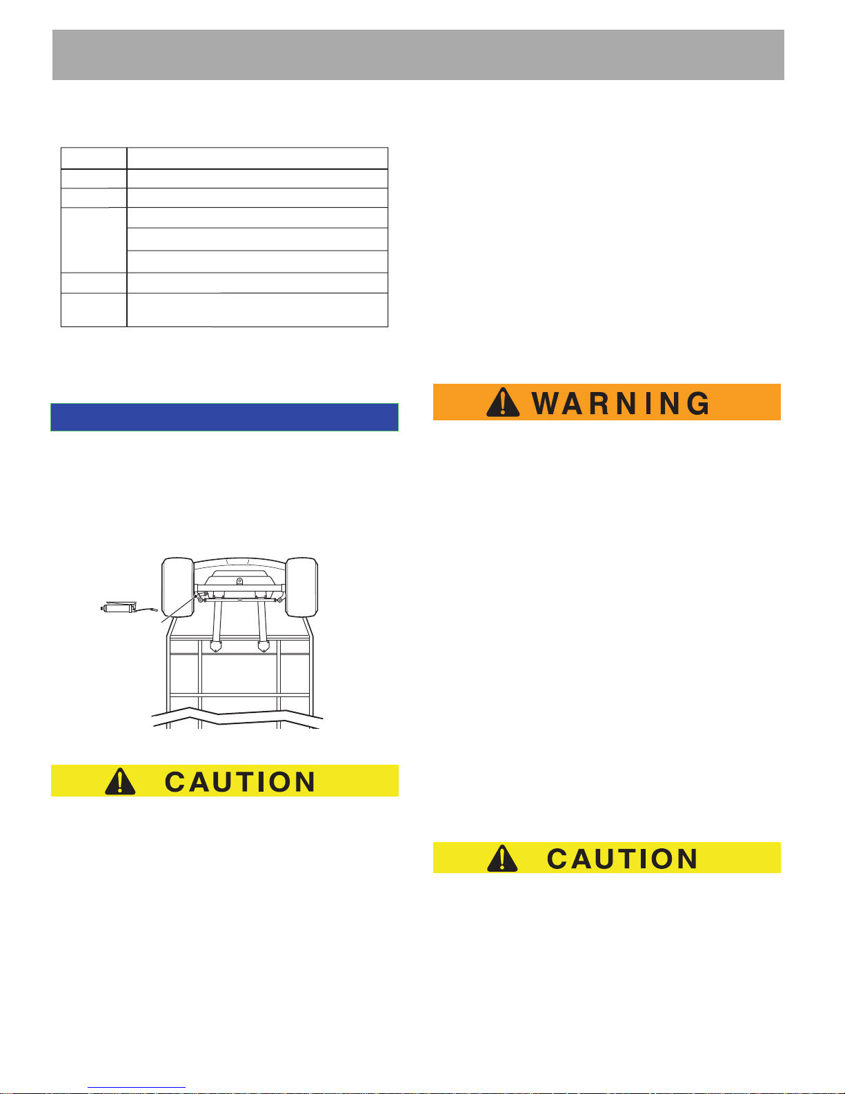
When lifting the vehicle, position jack stands only in the
areas indicated.
To raise the entire vehicle, install chocks in front and
behind each front wheel (Ref. Fig. 2). Center jack under
the rear frame crossmember. Raise vehicle and locate a
jack stand under outer ends of rear axle.
Lower the jack and test the stability of the vehicle on the
two jack stands.
Fig. 2 Lifting the Vehicle
Place the jack at the center of the front axle. Raise the
vehicle and position jack stands under the inner frame
member as indicated.
Lower the jack and test the stability of the vehicle on the
four jack stands.
If only the front or rear of the vehicle is to be raised,
place the chocks in front and behind each wheel not
being raised in order to stabilize the vehicle.
Lower the vehicle by reversing the lifting sequence.
Page B-4
Repair and Service Manual

SAFETY
Read all of Section B and this section before attempting any procedure. Pay particular attention to Notices, Cautions, Warnings and Dangers.
Notes:
Repair and Service Manual
Page B-5

SAFETY
Read all of Section B and this section before attempting any procedure. Pay particular attention to Notices, Cautions, Warnings and Dangers
Notes:
Page B-6
Repair and Service Manual

BODY
TABLE OF CONTENTS FOR SECTION ‘C’
SECTION TITLE PAGE NO.
BODY.............................................................................................................................C - 1
General................................................................................................................................. C - 1
BODY COMPONENT REPLACEMENT........................................................................C - 1
Instrument Panel Replacement ............................................................................................ C - 5
Cowl Replacement ............................................................................................................... C - 5
Front Fascia Replacement ................................................................................................... C - 5
Rocker Panel Replacement.................................................................................................. C - 5
Front Seat Pod Replacement ............................................................................................... C - 6
Rear Body Replacement ...................................................................................................... C - 6
Foot Rest Replacement........................................................................................................ C - 7
Rear Bumper Replacement .................................................................................................. C - 7
Front Seat Replacement....................................................................................................... C - 7
Front Facing Rear Seat ........................................................................................................ C - 7
Rear Facing Rear Seat......................................................................................................... C - 8
Cargo Bed Replacement ...................................................................................................... C - 8
Seat/Cargo Bed Latch .......................................................................................................... C - 8
PAINTING......................................................................................................................C - 8
Minor Scratches.................................................................................................................... C - 8
Larger Scratches .................................................................................................................. C - 9
Complete Panel Repair ........................................................................................................ C - 9
LIST OF ILLUSTRATIONS
Fig. 1 Drill Out Metal Rivet .............................................................................................................. C - 1
Fig. 2 Body Components (Front) ..................................................................................................... C - 2
Fig. 3 Body Components (Seats and Rear) .................................................................................... C - 3
Fig. 4 Body Components (Cargo Box and Seat Foot Rest) ............................................................ C - 4
Repair and Service Manual
Page C-i

BODY
Read all of Section B and this section before attempting any procedure. Pay particular attention to Notices, Cautions, Warnings and Dangers.
NOTES:
B
Page C-ii
Repair and Service Manual
BODY
NOTICE
Read all of Section B and this section before attempting any procedure. Pay particular attention to Notices, Cautions, Warnings and Dangers.
B
BODY
In the following text, there are references to removing/i nstalling
bolts etc. Additional hardware (nuts, washers etc.) that are
removed must always be installed in their original positions
unless otherwise specified. Non-specified torques are as
shown in the table in Section A.
General
To prevent possible injury or death from battery
explosion. Batteries should always be removed
before any servicing that will generate sparks. It
is important to use a sharp drill bit when removing the rivets on the side of the vehicle. Extreme
care must be used when drilling out the rivets
located in the front of the body and the bottom
side of the body. Excessive pressure could
result in the drill bit being forced through the
body panel and penetrating a component. As
extra protection, it is recommended that a protective piece of sheet metal be placed between
the battery and the rivet. Use of a drill depth
stop will provide additional protection.
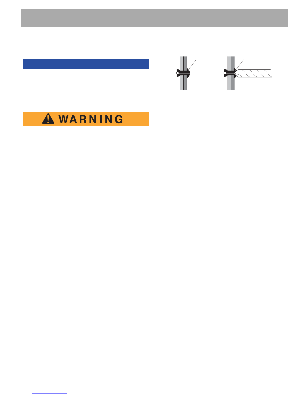
In general, body component replacement can be accomplished with a minimum of specialized tools. Most body
components are held in place with conventional removable hardware (nuts, bolts, washers and screws). Some
components are mounted with ‘pop’ rivets which require
that the rivet head be removed in order to push out the
shank of the rivet. The rivet head is easily removed by
drilling into the head with a sharp drill bit that is slightly
larger than the shank of the rivet (Ref. Fig. 1). Care must
be exercised when drilling to prevent the drill from being
forced through and damaging compo nent s wher e it could
damage components located immediately behind the
rivet. The best way to prevent this from occurring is to use
a sharp drill bit that requires very little pressure to cut successfully and to place a piece of protective sheet metal
between the surface being drilled and components
directly behind it.
Drill Out Rivet
Pop Rivet
Fig. 1 Drill Out Metal Rivet
Head Only
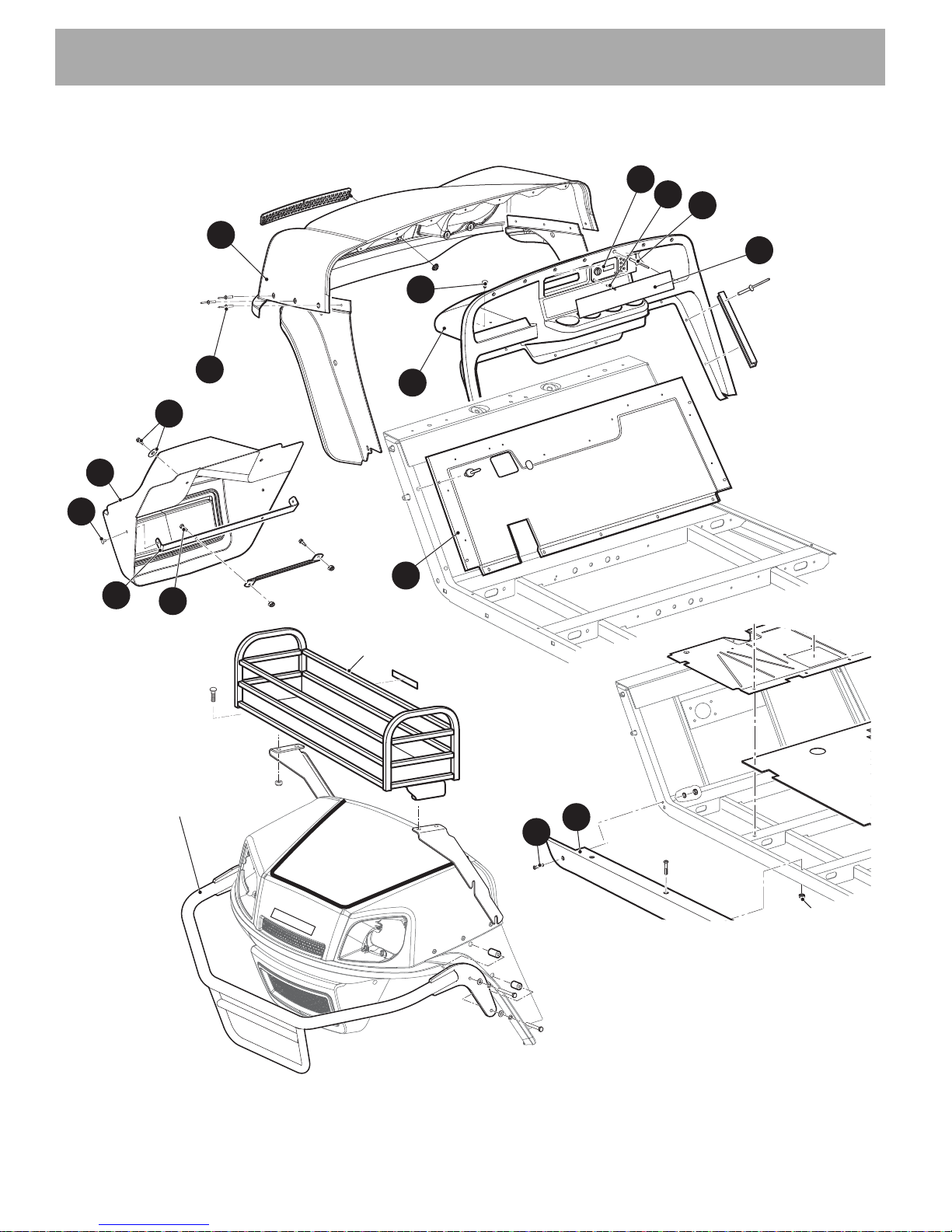
BODY COMPONENT REPLACEMENT
The body components can be replaced by removing the
securing hardware, replacing the component and securing with hardware in the same orientation as removed.
The illustrations on the following pages indicate the
assembly methods for the various components.
B
Repair and Service Manual
Page C-1
BODY
48
16
5
1
8
7
BRUSH GUARD
FRONT BASKET
4
6
9
10
11
28
143
139
144
145
141
Read all of Section B and this section before attempting any procedure. Pay particular attention to Notices, Cautions, Warnings and Dangers.
B
Page C-2
Fig. 2 Body Components (Front)
Repair and Service Manual
 Loading...