

Ezgo ELECTRIC POWERED PERSONNEL CARRIERS, GOLF CAR, Shuttle 2, Shuttle 4, Shuttle 6 Technician's Repair And Service Manual
...
600938
A Textron Company
TECHNICIAN’S
REPAIR AND SERVICE MANUAL
ISSUED SEPTEMBER 2004 REVISED OCTOBER 2007
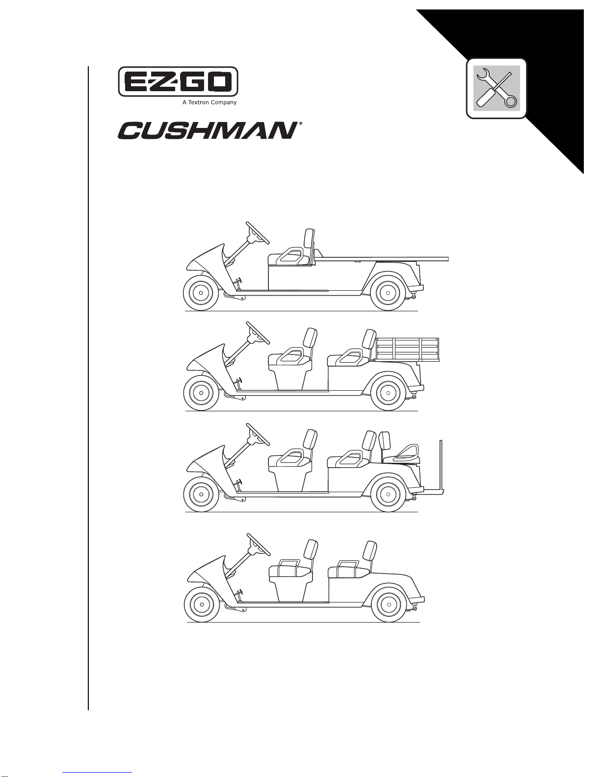
ELECTRIC POWERED
PERSONNEL CARRIERS
AND GOLF CAR
SAFETY
Read and understand all labels located on the vehicle. For any questions on any of the information, contact manufacturer’s representative for clarification.
Always replace any damaged or missing labels.
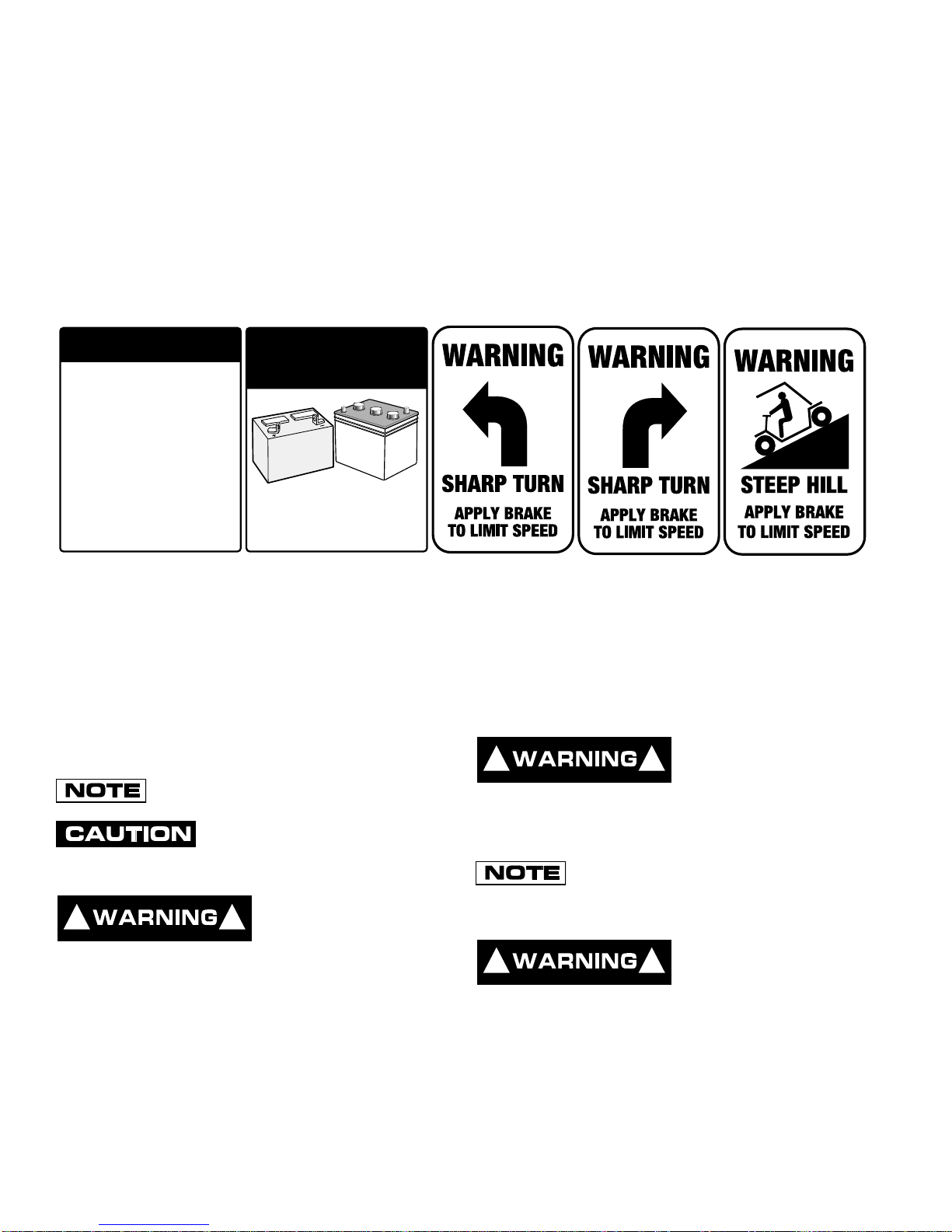
On steep hills it is possible for vehicles to coast at greater than normal speeds encountered on a flat surface. To pre-
vent loss of vehicle control and possible serious injury, speeds should be limited to no more than the maximum speed
on level ground. (See vehicle specification.) Limit speed by applying the service brake.
Catastrophic damage to the drive train components due to excessive speed may result from driving the vehicle above
specified speed. Damage caused by excessive speed may cause a loss of vehicle control, is costly, is considered
abuse and will not be covered under warranty.
If the vehicle is to be used in a commercial environment, signs similar to the ones illustrated should be used to warn of
situations that could result in an unsafe condition.
BATTERY WARNING
Battery posts,
terminals and related
accessories contain
lead and lead compounds,
chemicals known
to cause cancer and
reproductive harm.
WASH HANDS
AFTER HANDLING!
Be sure that this manual remains as part of the permanent service record should the vehicle be re -sold.
BATTERIES
AND RELATED PARTS
CONTAIN LEAD
WASH HANDS
AFTER HANDLING!
WARNING: Battery posts, terminals and related
accessories contain lead and lead compounds,
chemicals known to cause cancer and reproductive harm.
NOTES, CAUTIONS AND WARNINGS
Throughout this guide NOTE, CAUTION and WARNING
will be used.
A NOTE indicates a condition that should be
observed.
A CAUTION indicates a condition
that may result in damage to the
vehicle.
A WARNING
! !
indicates a
hazardous condition
that could result in severe injury or death.
Please observe these NOTES, CAUTIONS and WARNINGS; be aware that servicing a vehicle requires
mechanical skill and a regard for conditions that could be
hazardous. Improper service or repair may damage the
vehicle or render it unsafe.
! !
known, in certain quantities, to cause cancer, birth defects, or other reproductive
harm.
The exhaust emissions of this vehicles engine
is regulated by the Federal EPA. Significant
fines could result from modifications or tampering with the
engine, fuel, ignition or air intake systems.
! !
lead and lead compounds. Wash hands after
handling.
Engine exhaust from
this product contains chemicals
Battery posts, terminals and related accessories contain
(NOTES, CAUTIONS AND WARNINGS CONTINUED ON INSIDE OF BACK COVER)

TECHNICIAN’S REPAIR AND
SERVICE MANUAL
ELECTRIC
UTILITY VEHICLES
Shuttle 2
Shuttle 4
Shuttle 6
Bellhop 2
Bellhop 4
Bellhop 6
TXT 5E
STARTING MODEL YEAR: 2005
The E-Z-GO Division of Textron Inc. reserves the right to incorporate engineering and design changes to products in this Manual, without obligation to include
these changes on units leased/sold previously.
The information contained in this Manual may be revised periodically by the E-Z-GO Division, and therefore is subject to change without notice.
The E-Z-GO Division DISCLAIMS LIABLITY FOR ERRORS IN THIS MANUAL, and the E-Z-GO Division SPECIFICALLY DISCLAIMS LIABILITY FOR INCIDENTAL AND CONSEQUENTIAL DAMAGES resulting from the use of the information and materials in this Manual.
CUSTOMER SERVICE DEPARTMENT IN USA PHONE: 1-800-241-5855 FAX: 1-800-448-8124
OUTSIDE USA PHONE: 001-706-798-4311 FAX: 001-706-771-4609
E-Z-GO DIVISION OF TEXTRON INC., 1451 MARVIN GRIFFIN ROAD, AUGUSTA, GEORGIA USA 30906-3852
Owner’s Manual and Service Guide
Page i

NOTES
This vehicle has been designed and manufactured in the United States of America (USA) as
a ‘World Vehicle’. The Standards and Specifications listed in the following text originate in
the USA unless otherwise indicated.
The use of non Original Equipment Manufacturer (OEM) approved parts may void the
warranty.
Overfilling battery may void the warranty.
Tampering with or adjusting the governor to permit vehicle to operate at above factory
specifications will void the vehicle warranty.
When servicing engines, all adjustments and replacement components must be per original
vehicle specifications in order to maintain the United States of America Federal and State
emission certification applicable at the time of manufacture.
BATTERY PROLONGED STORAGE
All batteries will self discharge over time. The rate of self discharge varies depending on the
ambient temperature and the age and condition of the batteries.
A fully charged battery will not freeze in winter temperatures unless the temperature falls
below -75° F (-60° C).
Page ii
Owner’s Manual and Service Guide

TABLE OF CONTENTS
TITLE PAGE
Safety...........................................................................................................................Inside Covers
Notes.................................................................................................................................................ii
Safety Information............................................................................................................................ v
TITLE SECTION
General Information & Routine Maintenance...................................................................................A
Safety...............................................................................................................................................B
Body and Truckbed..........................................................................................................................C
Wheels and Tires .............................................................................................................................D
Front Suspension and Steering........................................................................................................E
Electronic Speed Control..................................................................................................................F
Brakes - Front Disc.......................................................................................................................... G
Brakes - Rear Mechanical................................................................................................................H
Electrical System.............................................................................................................................. J
Motor................................................................................................................................................K
Batteries and Charging.....................................................................................................................L
Rear Suspension.............................................................................................................................M
Rear Axle......................................................................................................................
Weather Protection...........................................................................................................................P
Paint................................................................................................................................................ Q
Troubleshooting................................................................................................................................R
Lightning Protection and Grounding.................................................................................................S
General Specifications .....................................................................................................................T
....................N
Repair and Service Manual
Page iii

Notes:
TABLE OF CONTENTS
Page iv
Repair and Service Manual

GENERAL INFORMATION & ROUTINE MAINTENANCE
TABLE OF CONTENTS FOR SECTION ‘A’
SECTION TITLE PAGE NO.
SERIAL NUMBER LABEL LOCATION ............................................................................................A - 1
TRANSPORTING VEHICLE ............................................................................................................A - 1
TOWING................................................................................................................................A - 1
HAULING...............................................................................................................................A - 1
SERVICING THE ELECTRIC VEHICLE..........................................................................................A - 1
ROUTINE MAINTENANCE..............................................................................................................A - 2
REAR AXLE.....................................................................................................................................A - 2
BRAKES................................................... ........................................................................................A - 2
TIRES..............................................................................................................................................A - 2
LIGHT BULB REPLACEMENT ........................................................................................................A - 2
CARE AND CLEANING OF THE VEHICLE.....................................................................................A - 2
VEHICLE CARE PRODUCTS..........................................................................................................A - 3
TOP AND WINDSHIELD..................................................................................................................A - 3
HARDWARE ....................................................................................................................................A - 4
A
TORQUE SPECIFICATIONS...........................................................................................................A - 4
PERIODIC SERVICE SCHEDULE...................................................................................................A - 5
LIST OF ILLUSTRATIONS
Fig. 1 Initial Service Chart ..............................................................................................................A - 1
Fig. 2 Lubrication Point...................................................................................................................A - 2
Fig. 3 Torque Specifications............................................................................................................A - 4
Fig. 4 Periodic Service Schedule ....................................................................................................A - 5
Repair and Service Manual
Page A-i

GENERAL INFORMATION & ROUTINE MAINTENANCE
Notes:
Page A-ii
Repair and Service Manual
GENERAL INFORMATION & ROUTINE MAINTENANCE
! !
! !
! !
Read all of Section B and this section before attempting any procedure. Pay particular attention to all Notes,
SERIAL NUMBER LABEL LOCATION
Two serial number and manufacture date code label are
on the vehicle. One is placed on the body below the
front, driver side of the seat. The other is located on the
chassis under the seat.
Design changes take place on an ongoing basis. In order
to obtain correct components for the vehicle, the manufacture date code, serial number and vehicle model must
be provided when ordering service parts.
TRANSPORTING VEHICLE
TOWING
following Warnings:
Do not attempt any type of servicing
operations before reading and understanding all notes, cautions and warnings in this manual.
Any servicing requiring adjustments to
be made to the powertrain while the
motor is running must be made with
both drive wheels raised.
Wear eye protection when
working on the vehicle. In particular, use care when working
around batteries, or using sol-
This vehicle is not
designed to be towed.
It is recommended that the vehicle be moved by placing
the entire vehicle on a trailer, flatbed truck or other suitable transport.
To reduce the possibility of causing an
electrical arc, which could result in a battery explosion, turn off all electrical
loads from the batteries before removing
vents or compressed air.
any heavy gauge battery wires.
HAULING
To reduce the possibility of severe injury or death while
transporting vehicle:
Secure the vehicle and contents.
Never ride on vehicle being transported.
Always remove windshield before trans-
porting.
Maximum speed with sun top installed is
50 mph (80 kph).
If the vehicle is to be transported at highway speeds, the
sun top must be removed and the seat bottom secured.
When transporting vehicle below highway speeds, check
for tightness of hardware and cracks in sun top at mounting points. Always remove windshield when transporting.
Always check that the vehicle and contents are adequately secured before transporting. The rated capacity
of the trailer or truck must exceed the weight of the vehicle (see GENERAL SPECIFICATIONS for vehicle
weight) and load plus 1000 lbs. (454 kg). Lock the park
brake and secure the vehicle using ratchet tie downs.
SERVICING THE ELECTRIC VEHICLE
To prevent the possibility of motor disintegration, never operate vehicle at full
throttle for more than 4 - 5 seconds while
vehicle is in a “no load” condition.
It is in the best interest of both vehicle owner and servicing dealer to carefully follow the procedures recommended in this manual. Adequate preventive
maintenance, applied at regular intervals, is the best
guarantee for keeping the vehicle both dependable and
economical.
Before a new vehicle is put into operation, it is recommended that the items shown in the INITIAL SERVICE
CHART be performed (Ref Fig. 1 on page A-1).
ITEM SER VICE OPERATION
Batteries Charge batteries
Seats Remove protective plastic covering
Brakes Check operation and adjust if necessary
Establish acceptable stopping distance
Check hydraulic brake fluid level
Tires Check air pressure (see SPECIFICATIONS)
Portable Remove from vehicle and properly mount
Charger
To prevent severe
injury or death,
resulting from
improper servicing techniques, observe the
Vehicle batteries must be fully charged before initial use.
Fig. 1 Initial Service Chart
A
Repair and Service Manual
Page A-1
GENERAL INFORMATION & ROUTINE MAINTENANCE
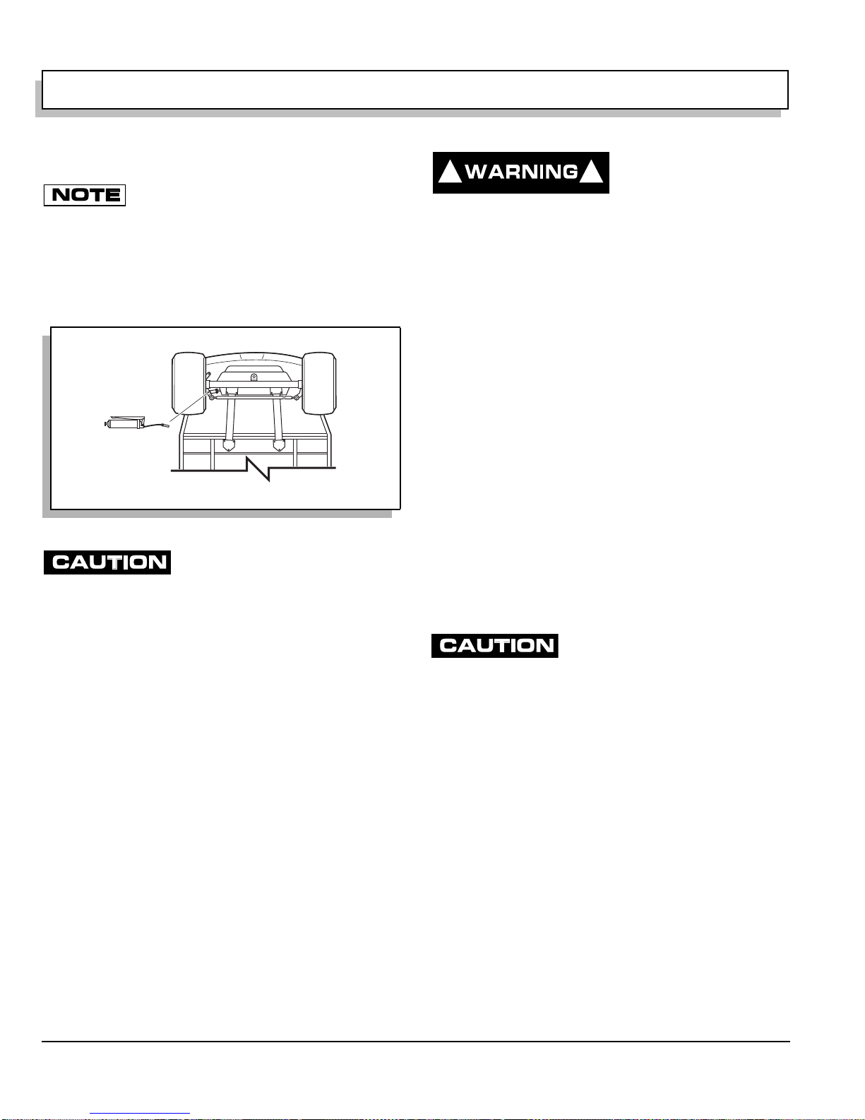
View From Underside Of Vehicle
Rack Ball Joint
Ref Lub 1
! !
Read all of Section B and this section before attempting any procedure. Pay particular attention to all Notes, Cautions and Warnings
ROUTINE MAINTENANCE
Some maintenance items must be serviced
more frequently on vehicles used under severe
driving conditions.
This vehicle will give years of satisfactory service providing it receives regular maintenance. Refer to the Periodic
Service Schedule for appropriate service intervals (Ref
Fig. 4 on page A-5). Refer to Lubrication Point for appropriate lubrication location (Ref Fig. 2 on page A-2).
Fig. 2 Lubrication Point
Do not use more than three (3)
pumps of grease for each grease
fitting at any one time- Excess grease may cause
grease seals to fail or grease migration into areas
that could damage components.
Putting more than three pumps of grease in a grease fitting could damage grease seals and cause premature
bearing failure.
REAR AXLE
The only maintenance required for the first five years is
the periodic inspection of the lubricant level. The rear
axle is provided with a lubricant level check/fill plug
located on the bottom of the differential. Unless leakage
is evident, the lubricant need only be replaced after five
years. The procedure to follow for checking the rear axle
lubricant level is in the REAR AXLE section.
BRAKES
After the vehicle has been put into service, it is recommended that the brakes be checked daily by performing
a brake test.
To prevent severe
injury or death
resulting from operating a vehicle with improperly operating
brake system, the braking system must be
properly maintained. All driving brake tests
must be done in a safe location with regard
for the safety of all personnel.
For information on conducting a brake test, refer to
BRAKES section.
TIRES
Tire condition should be inspected per the Periodic Service Schedule. Inflation pressures should be checked
when the tires are cool. Be sure to reinstall valve dust
cap after checking or inflating. For additional information,
refer to WHEELS AND TIRES section.
LIGHT BULB REPLACEMENT
Refer to ELECTRICAL SYSTEM for information regarding light bulb replacement.
CARE AND CLEANING OF THE
VEHICLE
When pressure washing vehi-
cle, do not use pressure in
excess of 700 psi (4825 kPa). To prevent cosmetic
damage, do not use any abrasive or reactive solvents to clean plastic parts.
It is important that proper techniques and cleaning materials be used. Using excessive water pressure may
cause damage to seals, plastics, the electrical system,
body finish or seat material. Do not use pressure in
excess of 700 psi (4825 kPa) to wash vehicle.
Normal cleaning of vinyl seats and plastic or rubber trim
require the use of a mild soap solution applied with a
sponge or soft brush and wipe with a damp cloth.
Removal of oil, tar, asphalt, shoe polish, etc. will require
the use of a commercially available vinyl/rubber cleaner.
The painted surfaces of the vehicle provide attractive
appearance and durable protection. Frequent washing
with lukewarm or cold water is the best method of preserving those painted surfaces.
Do not use hot water, strong soap or harsh chemical
detergents.
Page A-2
Repair and Service Manual
GENERAL INFORMATION & ROUTINE MAINTENANCE
! !
Read all of Section B and this section before attempting any procedure. Pay particular attention to all Notes, Cautions and Warnings
Rubber parts should be cleaned with non-abrasive
household cleaner.
Occasional cleaning and waxing with non-abrasive products designed for ‘clear coat’ automotive finishes will
enhance the appearance and durability of the painted
surfaces.
Corrosive materials used as fertilizers or for dust control
can collect on the underbody of the vehicle. These materials will accelerate corrosion of underbody parts. It is
recommended that the underbody be flushed occasionally with plain water. Thoroughly clean any areas where
mud or other debris can collect. Sediment packed in
closed areas should be loosened to ease its removal,
taking care not to chip or otherwise damage paint.
VEHICLE CARE PRODUCTS
To help maintain the vehicle, there are several products
available through local Distributors, authorized
Branches, or the Service Parts Department.
• Touch-up paint specially formulated to match vehi-
cle colors for use on TPE (plastic) bodies (P/N
28140-G** and 28432-G**).
• Multi-purpose Battery Protectant formulated to
form a long-term, flexible, non-tacky, dry coating
that will not crack, peel or flake over a wide temperature range (P/N 75500-G01).
• White Lithium Grease designed to provide lubrica-
tion protection in areas where staining or discoloring is a problem, or in areas of extreme
temperature ranges (P/N 75502-G01).
• Penetrant/Lubricant, a 4-in-1 product that pene-
trates the most stubborn of frozen parts, lubricates
leaving a light lubricating film, prevents corrosion
by adhering to wet or dry surfaces and displaces
moisture, sealing against future moisture return
(P/N 75503-G01).
• Multi-purpose Cleaner and Degreaser that con-
tains natural, environmentally safe solvents (P/N
75504-G01).
• Multi-purpose Hand Cleaner is an industrial
strength cleaner containing no harsh solvents, yet
gently lifts grease off hands. May be used with or
without water (P/N 75505-G01).
• Battery Cleaner that promotes easy, non-violent
neutralization of battery acids and battery acid
crystals. The resulting sodium salts are water soluble and easily washed away (P/N 75506-G01).
• Battery Maintenance Kit for complete battery
cleaning and watering, with battery maintenance
instructions (P/N 25587-G01).
• Biodegradable Cleaner that cleans the toughest
dirt and heavy soils by breaking down grease to
be easily wiped or rinsed away (P/N 75507-G01).
• Multi-purpose Value Pack sampler package
including 4 ounce (118 ml) aerosol cans of Battery
Protector, Penetrant/Lubricant, White Lithium
Grease, and Carburetor and Choke Cleaner (P/N
75508-G01).
• Plexus plastic cleaner and polish removes minor
scratches from windshield (P/N 28433-G**).
TOP AND WINDSHIELD
The top does not
provide protection
from roll over or fall-
ing objects.
The windshield does not provide protection from tree limbs or flying objects.
The top and windshield are designed for weather protection only.
Clean with lots of water and a clean cloth. Minor
scratches may be removed using a commercial plastic
polish or Plexus plastic cleaner available from Service
Parts Department.
Repair and Service Manual
Page A-3

GENERAL INFORMATION & ROUTINE MAINTENANCE
ALL TORQUE FIGURES ARE IN FT. LBS. (Nm)
BOLT SIZE
Grade 2
1/4" 5/16" 3/8" 7/16" 1/2" 9/16" 5/8" 3/4" 7/8" 1"
Unless otherwise noted in text, tighten all hardware in accordance with this chart.
This chart specifies 'lubricated' torque figures. Fasteners that are plated or lubricated when
installed are considered 'wet' and require approximately 80% of the torque required for 'dry' fasteners.
4
(5)
8
(11)
15
(20)
24
(33)
35
(47)
55
(75)
75
(102)
130
(176)
125
(169)
190
(258)
Grade 5
Grade 8
6
(8)
13
(18)
23
(31)
35
(47)
55
(75)
80
(108)
110
(149)
200
(271)
320
(434)
480
(651)
6
(8)
18
(24)
35
(47)
55
(75)
80
(108)
110
(149)
170
(230)
280
(380)
460
(624)
680
(922)
BOLT SIZE
Class 5.8
(Grade 2)
M4 M5 M6 M8 M10 M12 M14
1
(2)
2
(3)
4
(6)
10
(14)
20
(27)
35
(47)
55
(76.4)
Class 8.8
(Grade 5)
2
(3)
4
(6)
7
(10)
18
(24)
35
(47)
61
(83)
97
(131)
Class 10.9
(Grade 8)
3
(4)
6
(8)
10
(14)
25
(34)
49
(66)
86
(117)
136
(184)
5.8
8.8
10.9
Ref Tsp 1
Read all of Section B and this section before attempting any procedure. Pay particular attention to all Notes, Cautions and Warnings
HARDWARE
Periodically the vehicle should be inspected for loose
fasteners. Fasteners should be tightened in accordance
with the Torque Specifications table (Ref Fig. 3 on page
A-4).
TORQUE SPECIFICATIONS
Use care when tightening fasteners and refer to the
Technician’s Repair and Service Manual for specific
torque values.
Generally, two grades of hardware are used in the vehicle. Grade 5 hardware can be identified by the three
marks on the hexagonal head. Unmarked hardware is
Grade 2.
Page A-4
Fig. 3 Torque Specifications
Repair and Service Manual

GENERAL INFORMATION & ROUTINE MAINTENANCE
Read all of Section B and this section before attempting any procedure. Pay particular attention to all Notes, Cautions and Warnings
PERIODIC SERVICE SCHEDULE
3 Check Clean, Adjust, etc. S Replace
NOTE: Some maintenance items must be serviced more frequently on vehicles used under severe driving conditions
DAILY
BEFORE USE:
3 Check service brake general operation
3 Check park brake function
3 Check warning device function in reverse
3 Check tire condition
3 Check overall vehicle condition
BATTERIES Recharge to full charge state after each day’s use
CHARGER / RECEPTACLE 3 Inspect connector system at each charge
WEEKLY
TIRES
WHEELS 3 Check for bent rims, loose or missing lug nuts
3 Examine for cuts, excessive wear and pressure (See GENERAL
SPECIFICATIONS)
MONTHLY - 20 HOURS (includes items listed in previous table & the following)
BATTERIES
WIRING 3 Check all wiring for loose connections and broken/missing insulation
SERVICE BRAKE 3 Conduct brake performance test
BRAKE FLUID (IF EQUIPPED) 3 Check for leakage
ACCELERATOR 3 Check for smooth movement
CHARGER / RECEPTACLE Clean connections, keep receptacles free of dirt and foreign matter
DIRECTION SELECTOR 3 Check attachment, adjust as required
STEERING ASSEMBLY 3 Check for abnormal play, tightness of all hardware
TIE ROD/LINKAGES 3 Check for excessive play, bent components or loose connections
REAR AXLE 3 Check for leakage, add SAE 30 oil as required
Clean battery & terminals
3 Check charge condition and all connections
QUARTERLY - 50 HOURS (includes items listed in previous tables & the following)
FRONT AXLE 3 Check for damage to axle and loose or missing hardware
FRONT SHOCK ABSORBERS 3 Check for oil leakage and loose fasteners
FRONT SPRINGS 3 Check for loose hardware, cracks at attachments
Fig. 4 Periodic Service Schedule
Repair and Service Manual
Page A-5

GENERAL INFORMATION & ROUTINE MAINTENANCE
Read all of Section B and this section before attempting any procedure. Pay particular attention to all Notes, Cautions and Warnings
FRONT WHEEL ALIGNMENT 3 Check for unusual tire wear, align if required
3 Check for bent/binding linkage rod
PAR K B R A K E
REAR SHOCK ABSORBERS 3 Check for oil leakage, loose mounting hardware
3 Check for damage or wear to latch arm or catch bracket
Lubricate as required, use light oil. DO NOT LUBRICATE CABLES OR BRAKE
LATCH
HARDWARE AND FASTENERS
3 Check for loose or missing hardware and components
Tighten or replace missing hardware
SEMI-ANNUAL - 125 HOURS (includes items listed in previous tables & the following)
BATTERIES Clean batteries & terminals
DIRECTION SELECTOR 3 Check for wear and smooth movement (lubricate shaft with light oil if required)
KING PINS 3 Check for excessive play and tightness of retaining nuts
STEERING ASSEMBLY 3 Check bellows and pinion seal for damage or grease leakage
RACK END BALL JOINT Lubricate, use wheel bearing grease
REAR AXLE 3 Check for unusual noise and loose or missing mounting hardware
ANNUAL - 250-300 HOURS (includes items listed in previous tables & the following)
FRONT WHEEL BEARINGS Check and adjust if required (see FRONT SUSPENSION AND STEERING)
REAR AXLE 3 Check lubricant, add lubricant (SAE 30 oil) as required
SERVICE BRAKES
Clean and adjust, see Technician’s Repair and Service Manual
3 Check brake shoe linings, see Technician’s Repair and Service Manual
(HYDRAULIC BRAKES)
3 Check brake fluid
Fig. 4 Periodic Service Schedule
Page A-6
Repair and Service Manual

SAFETY
B
TABLE OF CONTENTS FOR SECTION ‘B’
SECTION TITLE PAGE NO.
GENERALANSI / NGCMA Z130.1-1993, Part II ..............................................................................B - 1
GENERAL (ASME / ANSI B56.8 - 1988)..........................................................................................B - 4
NOTES, CAUTIONS AND WARNINGS...........................................................................................B - 8
IMPORTANT SAFETY WARNING...................................................................................................B - 8
MODIFICATIONS TO VEHICLE ......................................................................................................B - 8
GENERAL MAINTENANCE.............................................................................................................B - 8
BEFORE SERVICING THE VEHICLE.............................................................................................B - 9
Additional Warnings...............................................................................................................B - 9
BATTERY REMOVAL & INSTALLATION......................................................................................B - 10
LIFTING THE VEHICLE.................................................................................................................B - 11
LIST OF ILLUSTRATIONS
Fig. 1 Battery Connections...........................................................................................................B - 10
Fig. 2 Lifting the Vehicle................................................................................................................B - 11
Repair and Service Manual
Page B-i

SAFETY
Notes:
Page B-ii
Repair and Service Manual

SAFETY
Read all of Section A and this section before attempting any procedure. Pay particular attention to all Notes,
GENERAL
The following text is provided as recommended by part II
of ANSI / NGCMA Z130.1 - 1993. The manufacturer, as a
member of the National Golf Car Manufacturers Association (NGCMA), strongly endorses the contents of this
specification.
5.2.1. Steep Grade
In areas where steep grades exist, golf car operations
should be restricted to the designated golf car pathways
where possible, and shall be identified with a suitable
warning giving the following information: “Warning, steep
grade, descend slowly with one foot on brake.”
PART II
5.2.2. Wet Areas
MAINTENANCE AND OPERATIONS
Wet grassy areas may cause a golf car to lose traction
and may affect stability. Wet areas shall be chained or
5. GENERAL SAFETY PRACTICES
5.1. Introduction
Like other machines, golf cars can cause injury if impr operly used or maintained. This section contains broad
safety practices recommended for safe golf car operations. Before operation, the controlling party should
establish such additional specific safety practices as may
be reasonably required for safe operations.
Experience has shown that golf cars which comply with
the provisions stated in Part II of this Standard are safe
when properly operated in accordance with the safety
and operation warnings affixed to ever y golf car. The safe
operation is enhanced when the golf cars are operated
within a specific set of operation instructions, safety rules
and practices established to meet actual operating terrain and conditions.
The safety information contained in Part II is intended to
provide the controlling party with basic safety information
and to encourage the controlling party to implement a
golf car safety program.
It is suggested and recommended that Part II be
reprinted in the golf car manufacturer’s operation and
service manuals to encourage safe operations and practices at the controlling party’s facility.
roped off to prevent golf car operations or be identified by
a suitable warning not to operate golf cars in this area
due to wet terrain.
5.2.3. Sharp Turns, Blind Corners, Bridge
Approaches
Sharp turns, blind spots, bridge approaches and other
potentially hazardous areas shall be either chained or
roped off to prevent golf car operations or identified with
a suitable warning to the operator of the nature of the
hazard and stating the proper precautions to be taken to
avoid the hazard.
5.2.4. Loose Terrain
Loose terrain may cause a golf car to lose traction and
may affect stability. Areas of loose terrain should be
repaired if possible, or chained or roped off to prevent
golf car operation or identified by a suitable warning to
operators not to operate golf cars in this area due to
loose terrain or possible hazardous conditions.
5.2.5. Golf Car/Pedestrian Interference Ar eas
B
5.2. Safety Survey
The controlling party shall perform a safety survey periodically, and as conditions warrant to their premises, to
identify areas where golf cars should not be operated
and to identify possible hazards.
Areas where pedestrians and golf cars interfere shall be
avoided whenever possible by rerouting the golf car traffic or the pedestrian traffic to eliminate th e inte rfer ence . If
elimination of the interference is not possible or is highly
impractical, signs shall be erected warning pedestrians
of the golf car traffic and golf car operators of the pedestrian traffic and to drive slowly and use extreme caution.
Repair and Service Manual
Page B-1

SAFETY
Read all of Section A and this section before attempting any procedure. Pay particular attention to all Notes, Cautions and Warnings
6. MAINTENANCE
6.1. Introduction
6.1.1. Golf cars may become hazardous if maintenance
is neglected or improperly performed. Therefore maintenance facilities, trained personnel and procedures in
accordance with the manufacturer’s recommendations
should be provided by the controlling party.
6.2. Preventive Maintenance
A regularly scheduled inspection and preventive maintenance program in accordance with the manufacturer’s
recommendations should be established. Such a program will be a valuable tool in providing the golfing
patron with a safe, properly operating golf car and
thereby help to avoid accidents.
6.2.1. Personnel
Only qualified, trained and authorized personnel shall be
permitted to inspect, adjust and maintain golf cars.
liters per car per charge. Because of the highly volatile
nature of hydrogen gas and its propensity to rise and
accumulate at the ceiling in pockets, a minimum of 5 air
changes per hour is recommended. The controlling party
shall consult applicable fire and safety codes for the specific ventilation levels required as well as the use of
explosion proof electrical apparatus.
6.2.4. Maintenance Procedures
All maintenance shall be performed in accordance with
the manufacturer’s recommended maintenance procedures as outlined in the manufacturer’s operation and
service manuals.
6.2.5. Maintenance Safety Procedures
All maintenance shall be performed in accordance with
the manufacturer’s recommended safety procedures as
outlined in the manufacturer’s operation and service
manuals. The following list of recommended safety procedures are general in nature and in no way supersede
the manufacturer’s specific instructions.
6.2.2. Parts and Materials
Only manufacturer’s recommended replacement parts
and materials shall be used.
6.2.3. Ventilation
Maintenance and storage areas shall be properly ventilated to avoid fire hazards in accordance with applicable
fire codes and ordinances.
6.2.3.1. Ventilation for gasoline powered golf cars shall
be provided to remove flammable vapors, fumes and
other flammable materials. Consult applicable fire codes
for specific levels of ventilation.
6.2.3.2. Ventilation for electric powered golf cars shall
be provided to remove the accumulation of flammable
hydrogen gas emitted during the charging process. The
amount of hydrogen gas emitted depends upon a number of factors such as the condition of the batteries, the
output rate of the battery charger and the amount of time
the batteries are on charge. Hydrogen emissions are
generally considered to be in the area of 10 to 20 cubic
6.2.5.1. Follow manufacturer’s instructions for immobilizing golf car before beginning any maintenance.
6.2.5.2. Block chassis before working underneath golf
car.
6.2.5.3. Before disconnecting any part of the fuel system, drain the system and turn all shut off valves to the
‘OFF’ position to prevent leakage or accumulation of
flammable fuels in the work area.
6.2.5.4. Avoid fire hazards and have fire protection
equipment available.
6.2.5.5. Before performing any maintenance on an electric golf car, disable the electrical system in accordance
with the manufacturer’s instructions.
6.2.5.6. Use only properly insulated tools when working
on electrically powered golf cars or around batteries.
Page B-2
Repair and Service Manual

SAFETY
Read all of Section A and this section before attempting any procedure. Pay particular attention to all Notes, Cautions and Warnings
6.2.5.7. Brakes, steering mechanisms, warning devices,
governors and all other safety devices shall be inspected
and maintained in a safe and proper operating condition
and shall not be modified as supplied by the manufacturer.
6.2.5.8. After each maintenance or repair the golf car
shall be driven by qualified, trained a nd authorized personnel to ensure proper operation and adjustment.
6.2.5.9. Driving golf car to check for proper operation
and adjustment after repair shall be performed in an a rea
that is free of vehicular and pedestrian traffic.
6.2.5.10. Record all maintenance performed in a maintenance record log by date, name of person performing
maintenance and type of maintenance. Controlling party
management should periodically inspect maintenance
log to ensure currency and completeness of entries.
7. FUELS HANDLING AND STORAGE/
BATTERY CHARGING
7.1. The controlling party shall supervise the storage
and handling of liquid fuels in accordance with applicable
fire and safety requirements.
7.2. Storage and handling of liquefied petroleum gas
fuels shall be in accordance with American Gas Association recommendations and applicable fire safety requirements.
7.3. The controlling party shall require battery changing and charging facilities and procedures to be in accordance with applicable ordinances or regulations (also
see paragraph 6.2.3.2).
7.4. The controlling party shall periodically inspect
facilities and review procedures to be certain that the
procedures in paragraphs 6.2.3.2 and 7.3 are being followed.
6.2.5.11. Provide operator comment cards to assist in
identifying non-periodic maintenance needs for specific
golf cars.
6.2.6. The controlling party shall maintain in a legible
condition all nameplates, warnings and instructions
which are supplied by the manufacturer.
6.2.7. The controlling party shall not perform any modification or addition which affects capacity or safe operation, or make any change not in accordance with the
owner’s manual without the manufacturer’s prior written
authorization. Where authorized modifications have been
made, the controlling party shall ensure that capacity,
operation, warning and maintenance instruction plates,
tags or decals are changed accordingly.
6.2.8. As required under paragraphs 6.2.6 and 6.2.7 the
manufacturer shall be contacted to secure new nameplates, warnings or instructions which shall then be
affixed in their proper place on the golf car.
8. OPERATING SAFETY RULES AND
PRACTICES
8.1. Operator Qualifications
8.1.1. Only authorized persons shall be allowed to oper-
ate golf cars. It is recommended that no persons be
allowed to operate golf cars except those persons who
posses a valid motor vehicle driver’s license.
8.1.2. The controlling party shall display the operation
and safety instructions as rec ommended by the golf car
manufacturers and the golf course safety rules in a conspicuous place near the golf car rental area or golf car
pick-up area. It is also recommended, as with all motor
vehicles, that the warning “Do not operate golf car s when
under the influence of alcohol or drugs.” be posted in a
conspicuous location.
End of ANSI/NGCMA Z130.1-1993, Part II
Repair and Service Manual
Page B-3

SAFETY
Read all of Section A and this section before attempting any procedure. Pay particular attention to all Notes, Cautions and Warnings
GENERAL
The following text is provided as recommended by part II
of ASME/ANSI B56.8-1988. The manufacturer strongly
endorses the contents of this specification.
PART II
FOR THE USER
4 GENERAL SAFETY PRACTICES
4.1 Introduction
4.1.1 Like other machines, carriers can cause injury
if improperly used or maintained. Part II contains broad
safety practices applicable to carrier operations. Before
operation, the user shall establish such additional specific safety practices as may reasonably be required for
safe operation.
4.2 Stability
4.2.1 Experience has shown that this vehicle, which
complies with this standard, is stable when properly
operated and when operated in accordance with specific
safety rules and practices established to meet actual
operating terrain and conditions. However, improper
operation, faulty maintenance, or poor housekeeping
may contribute to a condition of instability and defeat the
purpose of the standard. Some of the conditions which
may affect stability are failure of the user to follow safety
practices; also, ground and floor conditions, grade,
speed, loading, the operation of the carrier with improper
loads, battery weight, dynamic an d static forces, and the
judgement exercised by the carrier operator.
(a) The user shall train carrier operators to adhere
strictly to the operating instructions stated in this Standard.
(b) The user shall survey specific operat ing co nd itio ns
and environment, and establish and train carrier operators to comply with additional, specific safety practices.
4.3 Nameplates, Markings, Capacity, and Modifica-
tions
4.3.1 The user shall maintain in a legible condition
all nameplates, warnings, and instructions which are
supplied by the manufacturer.
4.3.2 The user shall not perform any modification or
addition which affects capacity or safe operation, or
make any change not in accordance with the owner’s
manual without the manufacturer’s prior written authorization. Where authorized modifications have been made,
the user shall ensure that capacity, operation, warning,
and maintenance instruction plates, tags, or decals are
changed accordingly.
4.3.3 As required under paras. 4.3.1 or 4.3.2, the
manufacturer shall be contacted to secure new nameplates, warnings, or instructions which shall then be
affixed in their proper place on the carrier.
4.4 Fuel Handling and Storage
4.4.1 The user shall supervise the storage and han-
dling of liquid fuels (when used) to be certain that it is in
accordance with appropriate paragraphs of ANSI/NFPA
505 and ANSI/NFPA 30.
4.4.2 Storage and handling of liquefied petroleum
gas fuels shall be in accordance with appropriate paragraphs of ANSI/NFPA 505 and ANSI/NFPA 58. If such
storage or handling is not in compliance with these standards, the user shall prevent the carrier from being used
until such storage and handling is in compliance with
these standards.
4.5 Changing and Charging Storage Batteries for
Electric Personnel and Burden Carriers
4.5.1 The user shall require battery changing and
charging facilities and procedures to be in accordance
with appropriate paragraphs of ANSI/NFPA 505.
4.5.2 The user shall periodically inspect facilities
and review procedures to be certain that appropriate
paragraphs of ANSI/NFPA 505, are strictl y complie d with,
and shall familiarize carrier operators with it.
4.6 Hazardous Locations
4.6.1 The user shall determine the hazard classifi-
cation of the particular atmosphere or location in which
the carrier is to be used in accordance with ANSI/NFPA
505.
4.6.2 The user shall permit in hazardous areas only
those carriers approved and of the type required by
ANSI/NFPA 505.
4.7 Lighting for Operating Areas
4.7.1 The user, in accordance with his responsibility
to survey the environment and operating conditio ns, shall
determine if the carrier requires lights and, if so, shall
equip the carrier with appropriate lights in accordance
with the manufacturer’s recommendations.
Page B-4
Repair and Service Manual

SAFETY
Read all of Section A and this section before attempting any procedure. Pay particular attention to all Notes, Cautions and Warnings
4.8 Control of Noxious Gases and Fumes
4.8.1 When equipment powered by internal com-
bustion engines is used in enclosed areas, the atmosphere shall be maintained within limits specified in the
American Conference of Governmental Industrial
Hygienists publication, “Threshold Limit Values for
Chemical Substances and Physical Agents in the Workroom Environment”. This shall be acco mp lish ed b y ve nt ilation provided by the user, and/or the installation, use,
and proper maintenance of emission control equipment
recommended or provided by the manufacturer of the
equipment.
4.9 Warning Device(s)
4.9.1 The user shall make periodic inspections of
the carrier to be certain that the sound-producing and/or
visual device(s) are maintained in good operating condition.
4.9.2 The user shall determine if operating conditions require the carrier to be equipped with additional
sound-producing and/or visual devices and be responsible for providing and maintaining such devices, in accordance with the manufacturer’s recommendations.
5 OPERATING SAFETY RULES AND
PRACTICES
5.1 Personnel and Burden Carrier Operator
Qualifications
5.1.1 Only persons who are trained in the proper
operation of the carrier shall be authorized to operate the
carrier. Operators shall be qualified as to visual, auditory,
physical, and mental ability to safely operate the equipment according to Section 5 and all other applicable
parts of this Standard.
5.2 Personnel and Burden Carrier Operators’
Training
5.2.1 The user shall conduct an operators’ training
program.
5.2.2 Successful completion of the operators’ training program shall be required by the user before operation of the carrier. The program shall be presented in its
entirety to all new operators and not cond ense d fo r th ose
claiming previous experience.
(a) instructional material provided by the manufac-
turer;
(b) emphasis on safety of passengers, material loads,
carrier operator, and other employees;
(c) general safety rules contained within this Standard
and the additional specific rules determined by the user
in accordance with this Standard, and why they were formulated;
(d) introduction of equipment, control locations and
functions, and explanation of how they work when used
properly and when used improperly, and surface conditions, grade, and other conditions of the environment in
which the carrier is to be operated;
(e) operational performance tests and evaluatio ns during, and at completion of, the program.
5.3 Personnel and Burden Carrier Operator
Responsibility
5.3.1 Operators shall abide by the following safety
rules and practices in paras. 5.4, 5.5, 5.6, and 5.7.
5.4 General
5.4.1 Safeguard the pedestrians at all times. Do not
drive carrier in a manner that would endanger anyo ne.
5.4.2 Riding on the carrier by persons other than the
operator is authorized only on personnel se at(s) provided
by the manufacturer. All parts of the body shall remain
within the plan view outline of the carrier.
5.4.3 When a carrier is to be left unattended, stop
carrier, apply the parking brake, stop the engine or turn
off power, turn off the control or ignition circuit, and
remove the key if provided. Block the wheels if machine
is on an incline.
5.4.4 A carrier is considered unattended when the
operator is 25 ft. (7.6 m) or more from the carrier which
remains in his view, or whenever the operator leaves the
carrier and it is not within his view. When the operator is
dismounted and within 25 ft. (7.6 m) of the carrier still in
his view, he still must have controls neutralized, and the
parking brake(s) set to prevent movement.
5.4.5 Maintain a safe distance from the edge of
ramps and platforms.
5.4.6 Use only approved carriers in hazardous locations, as defined in the appropriate safety standards.
5.2.3 The user should include in the operator s’ train-
ing program the following:
5.4.7 Report all accidents involving personnel,
building structures, and equipment.
Repair and Service Manual
Page B-5

SAFETY
Read all of Section A and this section before attempting any procedure. Pay particular attention to all Notes, Cautions and Warnings
5.4.8 Operators shall not add to, or modify, the car-
rier.
5.4.9 Carriers shall not be parked or left unattended
such that they block or obstruct fire aisles, access to
stairways, or fire equipment.
5.5 Traveling
5.5.1 Observe all traffic regulations, including autho -
rized speed limits. Under normal traffic conditions keep
to the right. Maintain a safe distance, based on speed of
travel, from a carrier or vehicle ahead; and keep the carrier under control at all times.
5.5.2 Yield the right of way to pedestrians, ambulances, fire trucks, or other carriers or vehicles in emergency situations.
5.5.3 Do not pass another carrier or vehicle traveling in the same direction at intersections, blind spots, or
at other dangerous locations.
5.5.4 Keep a clear view of the path of travel,
observe other traffic and personnel, and maintain a safe
clearance.
5.5.5 Slow down or stop, as conditions dictate, and
activate the sound-producing warning device at cross
aisles and when visibility is obstructed at other locations.
5.5.6 Ascend or descend grades slowly.
5.5.7 Avoid turning, if possible, and use extreme
caution on grades, ramps, or inclines; normally travel
straight up and down.
5.5.8 Under all travel conditions the carrier shall be
operated at a speed that will permit it to be brought to a
stop in a safe manner.
5.5.9 Make starts, stops, turns, or direction reversals in a smooth manner so as not to shift the load,
endanger passengers, or overturn the carrier.
5.5.10 Do not indulge in dangerous activities, such as
stunt driving or horseplay.
5.5.11 Slow down when approaching, or on, wet or
slippery surfaces.
5.5.12 Do not drive carrier onto any elevator unless
specifically authorized to do so. Approach elevators
slowly, and then enter squarely after the elevator car is
properly leveled. Once on the elevator, neutralize the
controls, shut off power, and set parking brakes. It is
advisable that all other personnel leave the elevator
before a carrier is allowed to enter or exit.
5.5.13 Avoid running over loose objects, potholes,
and bumps.
5.5.14 To negotiate turns, reduce speed to improve
stability, then turn hand steering wheel or tiller in a
smooth, sweeping motion.
5.6 Loading
5.6.1 Handle only stable and safely arranged loads.
When handling off-center loads which cannot be centered, operate with extra caution.
5.6.2 Handle only loads within the capacity of the
carrier as specified on the nameplate.
5.6.3 Handle loads exceeding the dimensions used
to establish carrier capacity with extra caution. Stability
and maneuverability may be adversely affected.
5.7 Operator Care of Personnel and Burden
Carriers
5.7.1 At the beginning of each shift during which the
carrier will be used, the operator shall check the carrier
condition and inspect the tires, warning devices, lights,
battery(s), speed and directional controllers, brakes, and
steering mechanism. If the carrier is found to be in need
of repair, or in any way unsafe, the matter shall be
reported immediately to the designated authority and the
carrier shall not be operated until it has been restored to
safe operating condition.
5.7.2 If during operation the carrier becomes unsafe
in any way, the matter shall be reported immediately to
the designated authority, and the carrier shall not be
operated until it has been restored to safe op e ratin g co ndition.
5.7.3 Do not make repairs or adjustments unless
specifically authorized to do so.
5.7.4 The engine shall be stopped and the operator
shall leave the carrier while refueling.
5.7.5 Spillage of oil or fuel shall be carefully and
completely absorbed or evaporated and fuel tank cap
replaced before starting engine.
5.7.6 Do not operate a carrier with a leak in the fuel
system or battery(s).
5.7.7 Do not use open flames for checking electrolyte level in storage battery(s) or liquid level in fuel tanks.
Page B-6
Repair and Service Manual

SAFETY
Read all of Section A and this section before attempting any procedure. Pay particular attention to all Notes, Cautions and Warnings
6 MAINTENANCE PRACTICES
6.1 Introduction
6.1.1 Carriers may become hazardous if mainte-
nance is neglected. Therefore, maintenance facilities,
trained personnel, and procedures shall be provided.
Such facilities may be on or off the premises.
6.2 Maintenance Procedures
6.2.1 Maintenance and inspection of all carriers
shall be performed in conformance with the manufacturer’s recommendations and the following practices.
(a) A scheduled preventive maintenance, lubrication,
and inspection system shall be followed.
(b) Only qualified and authorized personnel shall be
permitted to maintain, repair, adjust, and inspect carriers.
(c) Before undertaking maintenance or repair, follow
the manufacturer’s recommendations for immobilizing
the carrier.
(d) Block chassis before working underneath it.
(e) Before disconnecting any part of the engine fuel
system of a gasoline or diesel powered carrier with gravity feed fuel systems, be sure shutoff valve is closed, and
run engine until fuel system is depleted and engine stops
running.
(f) Before disconnecting any part of the engine fuel
system of LP gas powered carriers, close the LP gas cylinder valve and run the engine until fuel in the system is
depleted and the engine stops running.
(g) Operation to check performance of the car rier sh all
be conducted in an authorized area where safe clearance exists.
(h) Before commencing operation of th e carrie r, follow
the manufacturer’s instructions and recommended procedures.
(i) Avoid fire hazards and have fire protection equipment present in the work area. Do not use an ope n flam e
to check level or leakage of fuel, battery electrolyte, or
coolant. Do not use open pans of fuel or flammable
cleaning fluids for cleaning parts.
(j) Properly ventilate the work area.
(k) Handle LP gas cylinders with care. Physical damage, such as dents, scrapes, or gouges, may dangerously weaken the tank and make it unsafe for use.
(l) Brakes, steering mechanisms, speed and directional control mechanisms, warning devices, lights, governors, guards, and safety devices shall be inspected
regularly and maintained in a safe operating condition.
(m) Special carriers or devices designed and
approved for hazardous area operation shall be
inspected to ensure that maintenance preserves the original approved safe operating features.
(n) Fuel systems shall be checked for leaks and condition of parts. If a leak is found, action shall be taken to
prevent the use of the carrier until the leak has been
eliminated.
(o) The carrier manufacturer’s capacity, operation, and
maintenance instruction plates, tags, or decals shall be
maintained in legible condition.
(p) Batteries, motors, speed and directional controllers, limit switches, protective devices, electrical conductors, and connections shall be inspected and ma intained
in conformance with manufacturers recommended procedures.
(q) Carriers shall be kept in a clean condition to minimize fire hazards and facilitate detection of loose or
defective parts.
(r) Modifications and additions which affect capacity
and safe machine operation shall not be performed by
the customer or user without manufacturer’s prior written
authorization; where authorized modifications have been
made, the user shall ensure that capacity, operation,
warning, and maintenance instruction plates, tags, or
decals are changed accordingly.
(s) Care shall be taken to ensure that all replacement
parts are interchangeable with the original parts and of a
quality at least equal to that provided in the original
equipment.
End of ASME/ANSI B56.8-1988, Part II
Repair and Service Manual
Page B-7
SAFETY
Read all of Section A and this section before attempting any procedure. Pay particular attention to all Notes, Cautions and Warnings
NOTES, CAUTIONS AND WARNINGS
Throughout this manual, the following NOTES, CAUTIONS and WARNINGS are used. For the protection of
all personnel and the vehicle, be aware of and observe
the following:
A NOTE indicates a condition that should be
observed.
A CAUTION indicates a condition that may result in damage to
the vehicle or surrounding facilities.
A WARNING indicates a hazardous
condition which
could result in serious injury or death.
IMPORTANT SAFETY WARNING
In any product, components will eventually fail to perform
properly as the result of normal use, age, wear or abuse.
It is virtually impossible to anticipate all possible component failures or the manner in which each component
may fail.
Be aware that a vehicle requiring repair ind ica tes th at the
vehicle is no longer functioning as designed and therefore should be considered potentially hazardous. Use
extreme care when working on any vehicle. When diagnosing, removing or replacin g any components that are
not operating correctly, take the time to consider the
safety of yourself and others around you if the component should move unexpectedly.
Some components are heavy, spring loaded, highly corrosive, explosive or may produce high amperage or
reach high temperatures. Battery acid and hydrogen gas
could result in serious bodily injury to the technician/
mechanic and bystanders if not treated with utmost cau-
tion. Be careful not to place hands, face, feet or body in a
location that could expose them to injury should an
unforeseen situation occur.
Always use the appropriate tools listed in the tool list and
wear approved safety equipment.
MODIFICATIONS TO VEHICLE
To prevent personal
injury or death to the
operator or passenger(s), do not make changes to the weight
distribution or the center of gravity which
could make the vehicle unstable or prone to
roll over.
Do not modify the vehicle in any manner that will change
the weight distribution of the vehicle.
GENERAL MAINTENANCE
To prevent severe
injury or death
resulting from
improper servicing techniques, observe the
following Warnings:
Do not attempt any type of servicing operations before reading and understanding all
notes, cautions and warnings in this manual.
When any maintenance procedure or inspection is performed, it is important that care be exercised to insure
the safety of the technician/mechanic or bystanders and
to prevent damage to the vehicle.
Always read and understand the entire relevant manual
section (chapter) before attempting any inspection or
Page B-8
Repair and Service Manual

SAFETY
Read all of Section A and this section before attempting any procedure. Pay particular attention to all Notes, Cautions and Warnings
BEFORE SERVICING THE VEHICLE
Before attempting to inspect or service a vehicle, be sure
to read and understand the following warnings:
To prevent personal
injury or death,
observe the follow-
ing:
Before working on vehicle, remove all
jewelry (watches, rings, etc.).
Be sure that no loose clothing or hair
can become caught in the moving parts
of the powertrain.
Use care not to contact hot objects.
Any servicing requiring adjustments to
be made to the powertrain while the
motor is running must be made with
both wheels raised.
To prevent the possibility of motor disintegration, never operate vehicle at full
throttle for more than 4 - 5 seconds while
vehicle is in a “no load” condition.
Wear OSHA approved clothing and eye
protection when working on anything
that could expose the body or eyes to
potential injury. In particular, use care
when working with or around batteries,
compressed air or solvents.
Always turn the key switch to ‘OFF’ and
remove the key before disconnecting a
live circuit.
To prevent battery
explosion that could
result in severe personal injury or death, keep all smoking
materials, open flame or sparks away from
the batteries.
Hydrogen gas is generated in the charging cycle of batteries and is explosive in
concentrations as low as 4%. Because
hydrogen gas is lighter than air, it will
collect in the ceiling of buildings necessitating proper ventilation. Five air
exchanges per hour is considered the
minimum requirement.
Be sure that the key switch is off and all
electrical accessories are turned off
before starting work on vehicle.
Batteries should always be removed
before any servicing or repairs that
could generate sparks.
Never disconnect a circuit under load at
a battery terminal.
Batteries are heavy. Use
proper lifting techniques
when moving them. Always
lift the battery with a commercially available battery
lifting device. Use care not
to tip batteries when removing or installing them;
spilled electrolyte can
cause burns and damage.
When connecting battery cables, pay
particular attention to the polarity of the
battery terminals. Never confuse the
positive and negative cables.
The parking ‘PARK’ brake should always
be set, except for cases where the powertrain must be allowed to rotate or service is being performed on the brake
system.
If repairs are to be made that will require
welding or cutting, the batteries must be
removed.
Additional Warnings
Before working on the electrical system, be sure to read
and understand the following warnings that pertain to
electrical system repair or maintenance:
The electrolyte in a storage battery is an
acid solution which can cause severe
burns to the skin and eyes. Treat all electrolyte spills to the body and eyes with
extended flushing with clear water. Contact a physician immediately.
pressed air.
Any electrolyte spills should be neutral-
ized with a solution of 1/4 cup (60 ml)
sodium bicarbonate (baking soda) dissolved in 1 1/2 gallons (6 liters) of water
Repair and Service Manual
Wear eye protection when
working on the vehicle. In
particular, use care when
working around batteries, or
using solvents or com-
Page B-9
SAFETY
Read all of Section A and this section before attempting any procedure. Pay particular attention to all Notes, Cautions and Warnings
and flushed with water.
Wrap wrenches with
vinyl tape to prevent
the possibility of a
dropped wrench from
‘shorting out’ a battery, which could
result in an explosion and severe personal injury or death.
Aerosol containers of battery terminal
protectant must be used with extreme
care. Insulate metal container to prevent
can from contacting battery terminals
which could result in an explosion.
Overfilling batteries may result
in electrolyte being expelled
from the battery during the charge cycle. Expelled
electrolyte may cause damage to the vehicle and
storage facility.
BATTERY REMOVAL &
INSTALLATION
Tool List Qty. Required
Insulated wrench, 1/2"................. ... .... ... ... ... .... ... ... ... ... 1
Socket, 1/2", 3/8" drive................................................1
Ratchet, 3/8" drive.......................................................1
Battery carrier.............................................................. 1
Torque wrench (in. lbs.), 3/8" drive.............................. 1
In the following text, there are references to
removing/installing bolts etc. Additional hardware (nuts, washers etc.) that are removed must always be
installed in its original position unless otherwise specified. Non specified torques are as shown in table contained in Section
“A”.
Before any electrical service is
performed on PDS model vehicles, the Run-Tow/Maintenance switch must be
placed in the ‘Tow/Maintenance’ position.
If a power wire (battery, motor or controller) is disconnected for any reason on the PDS model vehicle,
the Run-Tow/Maintenance switch must be left in the
‘Tow/Maintenance’ position for at least 30 seconds
after the circuit is restored.
the vehicle batteries. Remove the battery hold down by
removing the hardware and lifting the retainer from the
batteries.
Remove the batteries using a commercial battery carrier.
If the batteries have been cleaned and any acid in the
battery rack area neutralized on a regular basis, no corrosion to the battery racks or surrounding area should be
present. If any corrosion is found, it should be immediately removed with a putty knife and wire brush. The area
should be washed with a solution of sodium bicarbonate
(baking soda) and water and thoroughly dried before
priming and painting with a corrosion resistant paint.
Place batteries into the battery rack. Install the battery
hold downs and tighten to 45 - 55 in. lbs. (5 - 6 Nm)
torque, to prevent movement but not tight enough to
cause distortion of the battery cases.
Inspect all wires and terminals and clean any corrosion
from the battery terminals or the wire terminals with a
solution of sodium bicarbonate (baking soda) and wire
brush if required.
Aerosol containers
! !
of battery terminal
protectant must be
used with extreme care. Insulate metal container to prevent can from contacting battery terminals which could result in an
explosion.
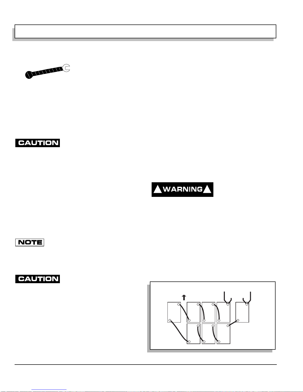
Use care to connect battery cables as shown in the following illustration (Ref Fig. 1 on page B-10). Connect
the positive (+) battery cable first, other battery connecting cables, and then connect the negative (-) cable
last. Ensure that all battery terminals are installed with
crimp up. Tighten the battery post hardware to 50 - 70 in.
lbs. (6 - 8 Nm).
cable terminals with a commercially available protective
coating.
Front of Vehicle
Protect the battery terminals and battery
-
To
Charger
+
+
-
BL+ to
Solenoid
+
-
+
-
-
+
-
-
BL- to Bon ESC
-
Turn vehicle key to ‘OFF’ and remove. Insure all optional
electrical accessories are turned OFF.
Using an insulated wrench, remove the negative (-) cable
first, the positive (+) cable and then all other cables from
Page B-10
Repair and Service Manual
+
Fig. 1 Battery Connections
+
+
SAFETY
Read all of Section A and this section before attempting any procedure. Pay particular attention to all Notes, Cautions and Warnings
LIFTING THE VEHICLE
Tool List Qty. Required
Floor jack ............................................ .... ... ... ... ........... 1
Jack stands......................................... ........................ 4
Chocks........................................................................ 4
Some servicing operations may require the vehicle be
raised.
Center of
Front Axle
To prevent possible
injury or death
resulting from a
vehicle falling from a jack, be sure the vehicle is on a firm and level surface. Never get
under a vehicle while it is supported by a
jack. Use jack stands and test the stability
of the vehicle on the stands. Always place
chocks in front and behind the wheels not
being raised. Use extreme care since the
vehicle is extremely unstable during the lifting process.
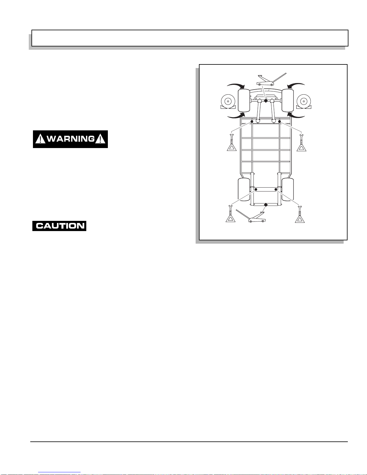
When lifting the vehicle, position
jack stands only in the areas
indicated.
To raise the entire vehicle, install chocks in front and
behind each front wheel (Ref Fig. 2 on page B-11). Center jack under the rear frame crossmember. Raise vehicle and locate a jack stand under outer ends of rear axle.
Lower the jack and test the stability of the vehicle on the
two jack stands.
Place the jack at the center of the front axle. Raise the
vehicle and position jack stands under the inner frame
member as indicated.
Lower the jack and test the stability of the vehicle on the
four jack stands.
If only the front or rear of the vehicle is to be raised, place
the chocks in front and behind each wheel not being
raised in order to stabilize the vehicle.
Lower the vehicle by reversing the lifting sequence
Center
of Rear
Bumper
View From Underside Of Vehicle
Fig. 2 Lifting the Vehicle
Flat Portion
of Frame
Outside End
of Rear Axle
Repair and Service Manual
Page B-11

SAFETY
Read all of Section A and this section before attempting any procedure. Pay particular attention to all Notes, Cautions and Warnings
Notes:
Page B-12
Repair and Service Manual

BODY
C
TABLE OF CONTENTS FOR SECTION ‘C’
SECTION TITLE PAGE NO.
BODY.............................................................................................................................................. C - 1
General................................................................................................................................. C - 1
BODY COMPONENT REPLACEMENT.......................................................................................... C - 1
Instrument Panel Replacement............................................................................................ C - 5
Cowl Replacement ............................................................................................................... C - 5
Front Shield Replacement.................................................................................................... C - 5
Rocker Panel End Replacement .......................................................................................... C - 6
Front Seat Pod Replacement............................................................................................... C - 6
Rear Body Replacement ...................................................................................................... C - 6
Foot Rest Replacement........................................................................................................ C - 7
Rear Bumper Replacement.................................................................................................. C - 7
Front Seat Replacement....................................................................................................... C - 8
Front Facing Rear Seat........................................................................................................ C - 8
Rear Facing Rear Seat......................................................................................................... C - 8
Cargo Bed Replacement...................................................................................................... C - 8
Seat/Cargo Bed Latch.......................................................................................................... C - 8
SHUTTLE / BELLHOP 2 REAR BODY........................................................................................... C - 9
Seat Support Removal ......................................................................................................... C - 9
Rocker Panel Removal....................................................................................................... C - 11
Rear Fender Removal........................................................................................................ C - 11
Rear Valence Panel Removal ............................................................................................ C - 12
Side Panel Removal........................................................................................................... C - 12
Load Deck Removal........................................................................................................... C - 12
Bulkhead Removal ............................................................................................................. C - 13
Seat Back Removal............................................................................................................ C - 13
Bed Frame Removal........................................................................................................... C - 14
Seat Frame Removal.......................................................................................................... C - 14
Mid Support Removal......................................................................................................... C - 15
Battery Rack Removal (Electric Vehicle Only) ................................................................... C - 16
Rear Bed Bracket Removal................................................................................................ C - 16
LIST OF ILLUSTRATIONS
Fig. 1 Drill Out Metal Rivet ............................................................................................................. C - 1
Fig. 2 Body Components (Front).................................................................................................... C - 2
Fig. 3 Body Components (Seats and Rear) ................................................................................... C - 3
Fig. 4 Body Components (Cargo Box, Seat, Foot Rest) ................................................................ C - 4
Fig. 5 Shuttle / Bellhop 2, Rear Body............................................................................................. C - 9
Fig. 6 Direction Selector Removal................................................................................................ C - 10
Fig. 7 Choke Cable Removal ....................................................................................................... C - 10
Fig. 8 Seat Support Removal....................................................................................................... C - 10
Fig. 9 Rocker Panel Removal....................................................................................................... C - 11
Fig. 10 Rear Fender Removal...................................................................................................... C - 11
Fig. 11 Rear Valence Panel Removal.......................................................................................... C - 12
Fig. 12 Side Panel Removal......................................................................................................... C - 12
Fig. 13 Load Deck Removal......................................................................................................... C - 13
Fig. 14 Bulkhead Removal........................................................................................................... C - 13
Fig. 15 Seat Back Removal.......................................................................................................... C - 13
Fig. 16 Bed Frame Removal ........................................................................................................ C - 14
Fig. 17 Seat Frame Removal ....................................................................................................... C - 14
Fig. 18 Mid Support Removal....................................................................................................... C - 15
Fig. 19 Battery Rack Removal...................................................................................................... C - 16
Fig. 20 Rear Bed Bracket Removal.............................................................................................. C - 16
Repair and Service Manual
Page C-i

BODY
Notes:
Page C-ii
Repair and Service Manual
 Loading...