


E-Z-GO 602080 User Manual

602080
TM
REVISED DATE: JAN. 2007
SAFETY
r
For any questions on material contai ned in this manual, contact an authorized representative for clarification.
Read and understand all labels located o n the vehi cle. Always replace any damaged or missing labe ls. See APPENDIX
A.
On steep hills it is possible for vehicles to coast at greater than normal speeds encountered on a flat surface. To pre-
vent loss of vehicle control and possible serious injury, speeds should be limited to no more than the maximum speed
on level ground. See GENERAL SPECIFICATIONS. Limit speed by applying the service brake.
Catastrophic damage to the drive train components due to excessive speed may result from driving the vehicle above
specified speed. Damage caused by excessive speed may cause a loss of vehicle control, is costly, is considered
abuse and will not be covered under warranty.
Be sure that this manual remains as part of th e permanent service record should the vehicle be sold.
For towing/transporting vehicle, refer to “TRANSPORTING VEHICLE”.
NOTES, CAUTIONS AND WARNINGS
Throughout this guide NOTE, CAUTION and WARNING
will be used.
A NOTE indicates a condition that should be
observed.
A CAUTION indicates a condition that
may result in damage to the vehicle.
A WARNING indicates a
! !
hazardous condition that
could result in severe
injury or death.
Observe these NOTES, CAUTIONS and WARNINGS;
be aware that servicing a vehicle requires mechanical
skill and a regard for conditions that could be hazardous.
Improper service or repair may damage the vehicle or
render it unsafe.
Engine exhaust from this
! !
product contains chemi-
cals known, in certain
quantities, to cause cancer, birth defects, or other
reproductive harm.
The exhaust emissions of this vehicles’ engine
complies with regulations set forth by the Environmental Protection Agency (EPA) of the United States of
America (USA) at time of manufacture. Significant fines could
result from modifications or tampering with the engine, fuel,
ignition or air intake systems.
Battery posts, terminals
! !
and related accessories
contain lead and lead
compounds. Wash hands after handling.
This spark ignition system meets all require-
ments of the Canadian Interference-Causing
Equipment Regulations.
Ce système d'allumage par étincelle de véhicule respecte
toutes les exigences du Règlement sur le matériel brouilleu
du Canada.
Read and understand the following warnings
before attempting to operate the vehicle:
To prevent personal
! !
injury or death, observe
the following:
When vehicle is to be left unattended, engage parking
brake, move direction selector to ‘F’ (forward)
position, turn key to ‘OFF’ position and remove key.
Drive vehicle only as fast as terrain and safety
considerations allow. Consider the terrain and traffic
conditions. Consider environmental factors which
effect the terrain and the ability to control the vehicle.
Avoid driving fast down hill. Sudden stops or change
of direction may result in a loss of control. Use service
brake to control speed when traveling down an incline.
Use extra care and reduced speed when driving on
poor surfaces, such as loose dirt, wet grass, gravel,
etc.
All travel should be directly up or down hills.
Use extra care when driving the vehicle across an
incline.
Stay in designated areas and avoid steep slopes. Use
the parking brake whenever the vehicle is parked.
Keep feet, legs, hands and arms inside vehicle at all
times.
Avoid extremely rough terrain.
(NOTES, CAUTIONS AND WARNINGS CONTINUED ON INSIDE OF BACK COVER)

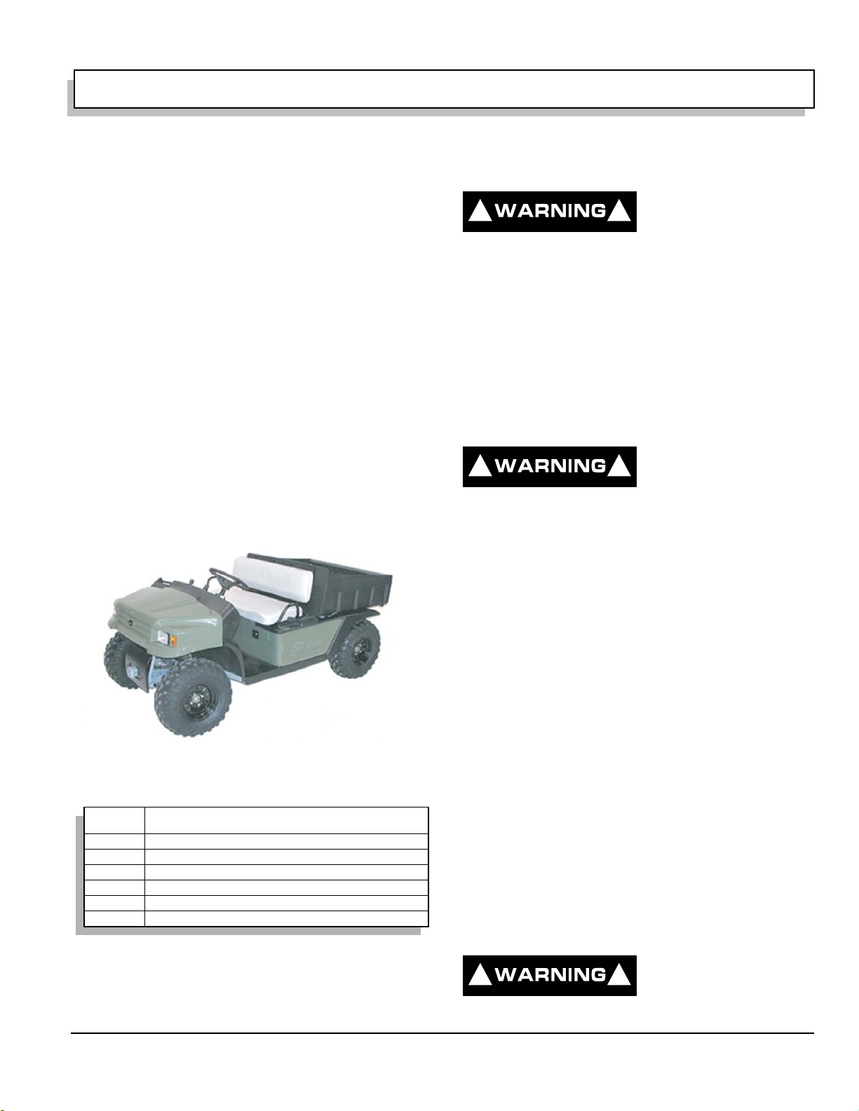
OWNER’S MANUAL
AND SERVICE GUIDE
GASOLINE POWERED
UTILITY VEHICLE
ST 4x4
STARTING MODEL YEAR 2005
E-Z-GO Division of TEXTRON, Inc. reserves the right to make design changes without obligation to make these changes on units previously sold and the information contained in this manual is subject to change without notice.
E-Z-GO Division of TEXTRON, Inc. is not liable for errors in this manual or for incidental or consequential damages that result from the use of the material in this
manual.
TO CONTACT US
NORTH AMERICA:
TECHNICAL ASSISTANCE & WARRANTY PHONE: 1-800-774-3946, FAX: 1-800-448-8124
SERVICE PARTS PHONE: 1-888-GET-EZGO (1-888-438-3946), FAX: 1-800-752-6175
INTERNATIONAL:
PHONE: 010-1-706-798-4311, FAX: 010-1-706-771-4609
E-Z-GO DIVISION OF TEXTRON, INC., 1451 MARVIN GRIFFIN ROAD, AUGUSTA, GEORGIA USA 30906-3852
Owner’s Manual and Service Guide
Page i

GENERAL INFORMATION
This vehicle has been designed and manufactured in the United States of America (USA) as
a ‘World Vehicle’. The Standards and Specifications listed in the following text originate in
the USA unless otherwise indicated.
The use of non Original Equipment Manufacturer (OEM) approved parts may void the
warranty.
Overfilling battery may void the warranty.
Tampering with or adjusting the governor to permit vehicle to operate at above factory
specifications will void the vehicle warranty.
When servicing engines, all adjustments and replacement components must be per original
vehicle specifications in order to maintain the United States of America Federal and State
emission certification applicable at the time of manufacture.
BATTERY PROLONGED STORAGE
All batteries will self discharge over time. The rate of self discharge varies depending on the
ambient temperature and the age and condition of the batteries.
A fully charged battery will not freeze in winter temperatures unless the temperature falls
below -75° F (-60° C).
Page ii
Owner’s Manual and Service Guide

TABLE OF CONTENTS
SAFETY ................................................................................................................ inside covers
GENERAL INFORMATION ...................................... ... ... ... ... .... ... ....................................... ... ... . ii
SAFETY INFORMATION ......................................................................................................... vii
WELCOME ............................... ....................... ...................... ....................... .................... .......... 1
BEFORE INITIAL USE ..............................................................................................................1
Fig.1 Initial Service Chart ...........................................................................................................1
CAPABILITIES .......................................................................................................................... 1
TERRAIN .............................................................................................................................................................1
VEHICLE CAPACITY ..........................................................................................................................................1
MODIFICATIONS TO VEHICLE ..........................................................................................................................2
COMMON SENSE OPERATION ...............................................................................................2
RUN-IN ............................ ................................................... ........................................................ 2
CONTROLS & INDICATORS ....................................................................................................3
SERVICE BRAKE PEDAL ...................................................................................................................................3
Fig. 2 Service Brake Pedal ........................................................................................................3
CHOKE ................................................................................................................................................................3
IGNITION SWITCH ..............................................................................................................................................3
DIRECTION SELECTOR .....................................................................................................................................4
2WD/4WD SELECTOR ....................................................................................................................................... 5
DIFFERENTIAL LOCK ........................................................................................................................................5
ACCELERATOR ..................................................................................................................................................6
FUEL .......................................................................................................................................... 6
FUEL GAUGE ......................................................................................................................................................6
LOW OIL PRESSURE INDICATOR LIGHT .........................................................................................................6
LIGHT SWITCHES ..............................................................................................................................................7
12 VOLT POWER OUTLET .................................................................................................................................7
STARTING AND DRIVING ... ... ... ....................................... ... .... ... ... ... .... ... ................................. 8
STARTING VEHICLE ON A HILL ........................................................................................................................8
COASTING ..........................................................................................................................................................8
LOAD BED ................................................................................................................................. 8
TAILGATE ...........................................................................................................................................................9
MANUAL LIFT BED .............................................................................................................................................9
ELECTRIC LIFT BED OPERATION ....................................................................................................................9
WINCH ....................................................................................................................................... 9
WINCH APPLICATIONS .....................................................................................................................................9
WINCH MOUNTING ..........................................................................................................................................10
WINCH OPERATION ........................................................................................................................................10
Fig. 3 Park Brake and Indicator .................................................................................................3
Fig. 4 Choke ..............................................................................................................................4
Fig. 5 Ignition Switch ..................................................................................................................4
Fig. 6 Direction Selector and Differential Locks .........................................................................4
Fig. 7 2WD/4WD Selector ..........................................................................................................5
Fig. 8 Differential Lock ...............................................................................................................5
Fig. 9 Accelerator Pedal ............................................................................................................6
Fig. 10 Fuel Tank and Gauge ....................................................................................................7
Fig. 11 Low Pressure Oil Light ...................................................................................................7
Fig. 12 Light Switches ................................................................................................................7
Fig. 13 Power Outlet ..................................................................................................................7
Fig. 14 Manual Lift Bed Release ................................................................................................9
Fig. 15 Electric Lift Bed Switch ..................................................................................................9
Fig. 16 Do Not Pull at Angle ....................................................................................................10
Fig. 17 Mounting Winch ...........................................................................................................11
Fig. 18 Use Nylon Sling and Install a Damper when Winching ................................................11
Fig. 19 Winch Operation ..........................................................................................................12
Owner’s Manual and Service Guide
Page iii

TABLE OF CONTENTS
TOP AND WINDSHIELD ..........................................................................................................12
TRANSPORTING VEHICLE ....................................................................................................12
TOWING ........................................................................................................................................................... 12
HAULING .................................................................................................................................12
TOWING A TRAILER .............................. ... ....................................... ... ... ... .... ... .......................12
OPENING THE COWL (HOOD) ........................................................... ... ... .... ... ... ....................13
Fig. 20 Unlatching Cowl .......................................................................................................... 13
DATA LABEL LOCATION .......................................................................................................13
MAINTENANCE .......................................................................................................................14
PERIODIC SERVICE SCHEDULE ...........................................................................................15
Fig. 21 Periodic Service Schedule .......................................................................................... 15
BASIC SERVICE PARTS .........................................................................................................16
Fig. 22 Basic Service Parts ..................................................................................................... 16
LIFTING THE VEHICLE ................................................ .... ... ... ... ... ....................................... ... .17
Fig. 23 Lifting the Vehicle ........................................................................................................ 17
OIL .................................... .................................... ................................ ....................................17
OIL LEVEL CHECK .......................................................................................................................................... 18
OIL CHANGE .................................................................................................................................................... 18
OIL FILTER CHANGE ...................................................................................................................................... 18
SPARK PLUGS ........................................................................................................................19
ALTERNATOR BELT ...............................................................................................................19
ADJUSTING BELT ............................................................................................................................................ 19
AIR CLEANER .............................. ... ... .... ...................................... .... ... ... ... .... ..........................20
CANISTER TYPE AIR CLEANER .................................................................................................................... 20
CLEANING AIR FILTER ELEMENT ................................................................................................................. 20
FUEL FILTER ................................ ... ....................................... ... ..............................................20
LUBRICATION POINTS ...........................................................................................................21
BATTERY ...................................... .................................... ...................................... .................21
BATTERY CLEANING ...................................................................................................................................... 22
JUMP STARTING ......................................................... .... ... ... ... ....................................... ... ....22
VEHICLE CLEANING AND CARE ..........................................................................................22
CLEANING ........................................................................................................................................................ 22
CARE PRODUCTS ........................................................................................................................................... 23
LABELS AND PICTOGRAMS .................................................................................................23
WHEELS AND TIRES ..............................................................................................................24
TIRE INSPECTION AND INFLATION .............................................................................................................. 24
REMOVAL AND INSTALLATION ..................................................................................................................... 24
Fig. 24 Recommended Oil ...................................................................................................... 17
Fig. 25 Oil Fill and Level Check .............................................................................................. 18
Fig. 26 Oil Change .................................................................................................................. 18
Fig. 27 Oil Filter Change ......................................................................................................... 19
Fig. 28 Adjusting Alternator Belt ..............................................................................................20
Fig. 29 Air Cleaner .................................................................................................................. 20
Fig. 30 Fuel Filter .................................................................................................................... 21
Fig. 31 Lubrication Points ........................................................................................................ 21
Fig. 32 Cleaning Battery .......................................................................................................... 22
Fig. 33 Jump Starting .............................................................................................................. 23
Fig. 34 Wheel Tightening Sequence ....................................................................................... 24
Page iv
Owner’s Manual and Service Guide

TABLE OF CONTENTS
LIGHT BULB REPLACEMENT ............................................................................................... 25
Fig. 35 Headlight Replacement ...............................................................................................25
FUSE REPLACEMENT ........................................................................................................... 25
SPARK ARRESTER ................................................................................................................25
Fig. 36 Cleaning Spark Arrester ..............................................................................................25
PROLONGED STORAGE ................................. ... .... ... ... ... ... ....................................... ... .... ... .. 25
FRONT AND REAR AXLES ....................................................................................................26
CHECKING LUBRICANT LEVEL ......................................................................................................................26
TRANSFER CASE ................................................................................................................... 26
CHECKING LUBRICANT LEVEL ......................................................................................................................26
AIR INTAKE AND COOLING FINS ............................... ... ... .... ... ... ... .... ... ... ............................ 26
BRAKES .................................................................................................................................. 27
PERIODIC BRAKE TEST FOR HYDRAULIC BRAKES ....................................................................................27
CAPACITIES ............................ ....................... ...................... ....................... .................... ........ 27
HARDWARE ............................................................................................................................ 28
GENERAL SPECIFICATIONS.................................................................................................. 29
VEHICLE WARRANTIES ......................................................................................................... 33
EMISSION CONTROL SYSTEM WARRANTY STATEMENT .................................................35
ENGINE OWNER WARRANTY POLICY ................................................................................. 35
INTERNATIONAL WARRANTY STATEMENT........................................................................ 35
DECLARATION OF CONFORMITY (EUROPE ONLY)............................................................ 37
LABELS AND PICTOGRAMS..... .... ... ... ... ....................................... ... .... ... ... ... ... .... ... ........... A - 1
Fig. 37 Checking Axle Lubricant ..............................................................................................26
Fig. 38 Checking Transfer Case Lubricant ..............................................................................26
Fig. 39 Cleaning Air Intake and Cooling Fins ..........................................................................27
Fig. 40 Capacities ....................................................................................................................27
Fig. 41 Torque Specifications and Bolt Grades .......................................................................28
Fig. 42 Vehicle Dimensions......................................................................................................31
Fig. 43 Vehicle Incline Specifications .......................................................................................31
Fig. 44 Vehicle Turning Clearance Diameter and Intersecting Aisle Clearance.......................32
Fig. 45 Label Locations......................................................................................... Appendix A - 3
Fig. 46 Pictogram Definitions................................................................................ Appendix A - 4
Fig. 47 Pictogram Definitions................................................................................ Appendix A - 5
Fig. 48 Pictogram Definitions................................................................................ Appendix A - 6
Fig. 49 Pictogram Definitions................................................................................ Appendix A - 7
Owner’s Manual and Service Guide
Page v

N
TABLE OF CONTENTS
otes:
Page vi
Owner’s Manual and Service Guide

SAFETY INFORMATION
This manual has been designed to assist in maintaining the vehicle in accordance with procedures developed by the
manufacturer. Adherence to these procedures and troubleshooting tips will ensure the best possible service from the
product. To reduce the chance of personal injury or property damage, the following must be carefully observed:
GENERAL
Many vehicles are used for a variety of tasks beyond the original intended use of the vehicle; therefore, it is impossible
to anticipate and warn against every possible combination of circumstances that may occur. No warnings can take the
place of good common sense and pruden t dr ivin g pr ac tice s.
Good common sense and prudent driving practices do more to prevent accidents and injury than all of the warnings
and instructions combined. The manufacturer strongly suggests that all users and maintenance personnel read this
entire manual paying particular attention to the CAUTIONS and WARNINGS contained therein.
If you have any questions regardin g this vehicle, contact your closest representative or write to the address o n the
back cover of this publication, Attention: Product Service Department.
The manufacturer reserves the right to make design changes without obligation to make these changes on units previously sold and the information contained in this manual is subject to change without notice.
The manufacturer is not liable for errors in this manual or for incidental or consequential damages that result from the
use of the material in this manual.
This vehicle conforms to the current applicable standard(s) for safety and performance requirements.
These vehicles are designed and manufactured for off-road use. They do not conform to Federal Motor Vehicle Safety
Standards of the United States of America (USA) and are not equipped for operation on public streets. Some communities may permit these vehicles to be operated on their streets on a limited basis and in accordance with local ordinances.
Refer to GENERAL SPECIFICATIONS for vehicle seating capacity.
Never modify the vehicle in any way that will alter the weight distribution of the vehicle, decrease its stability
or increase the speed beyond the factory specification. Such modifications can cause serious personal injury
or death. Modifications that increase the speed and/or weight of the vehicle will extend the stopping distance and may
reduce the stability of the vehicle. Do not make any such modifications or changes. The manufacturer prohibits and
disclaims responsibility for any such modifications or any other alteration which would adversely affect the safety of the
vehicle.
Vehicles that are capable of higher speeds must limit their speed to no more than the sp eed of other vehicles when
used in a golf course environment. Additionally, speed should be further moderated by the environmental conditions,
terrain and common sense.
GENERAL OPERATION
Always:
• Use the vehicle in a responsible manner and maintain the vehicle in safe operating condition.
• Read and observe all warnings and operation instruction labels affixed to the vehicle.
• Follow all safety rules established in the area where the vehicle is being operated.
• Reduce speed to compensate for poor terrain or conditions.
Owner’s Manual and Service Guide
Page vii

SAFETY INFORMATION
• Apply service brake to control speed on steep grades.
• Maintain adequate distance between vehicles.
• Reduce speed in wet areas.
• Use extreme caution when approaching sharp or blind turns.
• Use extreme caution when driving over loose terrain.
• Use extreme caution in areas where pedestrians are present.
MAINTENANCE
Always:
• Maintain the vehicle in accordance with the manufacturer’s periodic service schedule.
• Ensure that repairs are performed by those that are trained and qualified to do so.
• Follow the manufacturer’s maintenance procedures for the vehicle. Be sure to disable the vehicle before performing
any maintenance. Disabling includes removing the key from the key switch and removal of a battery wire.
• Insulate any tools used within the battery area in order to prevent sparks or battery explosion caused by shorting the
battery terminals or associated wiring. Remove the battery or cove r exposed terminals with an insulating material.
• Use specified replacement parts. Never use replacement parts of lesser quality.
• Use recommended tools.
• Determine that tools and procedures not specifically recommended by the manufacturer will not compromise the
safety of personnel nor jeopardize the safe operation of the vehicle.
• Support the vehicle using wheel chocks and jack stands. Never get under a vehicle that is supported by a jack. Lift
the vehicle in accordance with the manufacturer’s instructions.
• Empty the fuel tank or plug fuel hoses to prevent fuel leakage.
• Maintain the vehicle in an area away from exposed flame or perso ns who are smoking.
• Be aware that a vehicle that is not performing as designed is a potential hazard and must not be operated.
• Test drive the vehicle after any repairs or maintenance. All tests must be conducted in a sa f e area th at is free of both
vehicular and pedestrian traffic.
• Replace damaged or missing warning, caution or information labels.
• Keep complete records of the maintenance history of the vehicle.
The manufacturer cannot anticipate all situations, therefore people attempting to maintain or repair the vehicle must
have the skill and experience to recognize and protect themselves from potential situations that could result in severe
personal injury or death and damage to the vehicle. Use extreme caution and, if unsure as to the potential for injury,
refer the repair or maintenance to a qualified mechanic.
Page viii
Owner’s Manual and Service Guide

SAFETY INFORMATION
VENTILATION
Always store gasoline vehicles in a well ventilated area. Ventilation prevents gasoline fumes from accumulating.
Never fuel a vehicle in an area that is subject to flame or spar k. Pay p articular att ention to natur al gas or prop ane water
heaters and furnaces.
Never work around or operate a vehicle in an e nvironment t hat does no t ventilat e exhaust ga ses f rom the ar ea. Carb on
monoxide is a dangerous gas that can cause unconsciousne ss and is potentially lethal.
Owner’s Manual and Service Guide
Page ix

Notes:
SAFETY INFORMATION
Page x
Owner’s Manual and Service Guide

SAFETY INFORMATION
Read all of manual to become thoroughly familiar with this vehicle. Pay particular attention to all Notes, Cautions and Warnings
GENERAL
The following text is provided as recommended by part II
of SAE J2258 DEC 2003. E-Z-GO strongly endorses the
contents of this specification.
B.1 PART II
FOR THE CONTROLLING PARTY
B.1.1 Maintenance and Operations
B.1.1.1 Introduction
B.1.1.1.1 Like other machines, light utility vehicles
can cause injury if improperly used or maintained. Part II
contains broad safety practices applicable to vehicle
operations. Before operation, the controlling party shall
follow such additional specific safety practices as may
reasonably be required for safe operation.
B.1.1.1.2 Safety Survey-The controlling party shall
perform a safety survey of their premises periodically,
and as conditions warrant, identify areas where vehicles
should not be operated and to identify possible hazards.
(a) Steep Grade-In areas where steep grades exist,
vehicle operation should be restricted to the designated
vehicle's pathways where possible, and shall be identified with a suitable warning giving the following information: “Warning, steep grade, descend slowly.”
(b) Wet Areas-Wet areas could cause a vehicle to lose
traction and could affect steering, stability and braking.
(c) Sharp Turns, Blind Corners, Bridge ApproachesSharp turns, blind spots, bridge approaches, and other
potentially hazardous areas shall be identified with a suitable warning to the operator of the nature of the hazard
and stating the proper precautions to be taken to avoid
the hazard.
(d) Loose Terrain-Loose terrain could cause a vehicle
to lose traction and could affect steering, stability, and
braking.
B.1.1.1.3 Utility Vehicle/Pedestrian Interference
Areas-Areas where pedestrian and vehicle traffic could
interfere should be avoided by rerouting the vehicle or
the pedestrian traffic to eliminate t he int erf erence. If elim ination of the interference is not possible or is highly
impractical, signs shall be erected warning pedestrians
and vehicle operators of traffic cond itions and to u se caution.
B.1.1.1.4 The controlling party shall train vehicle
operators to adhere strictly to the operating instructions
stated in vehicle operator's manual and those additional
operating instructions provided by controlling party.
B.1.1.1.5 The controlling party shall survey specific
operating conditions and environment, establish safety
practices, and train vehicle operators to comply with
these practices.
B.1.1.2 Operation Experience has shown that vehicles which comply with the provisions stated in 7.8 are
stable when properly operated in accordance with specific safety rules and practices established t o meet actua l
operating terrain and conditions. However, improper
operation, faulty maintenance, or poor housekeeping
may contribute to a condition of instability and defeat the
purpose of the standard. Some conditions which could
affect stability are failure of the operator to follow safety
practices, surface conditions, grade, speed, loading,
braking, turning, improper loads, towing, attachments,
dynamic forces, and the judgment exercised by the vehicle operator.
B.1.1.3 Nameplates, Markings, Capacity, And Modifications.
B.1.1.3.1 The controlling party shall maintain in a legi-
ble condition all nameplates, warnings, and instructions
which are supplied by the vehicle manufacturer.
B.1.1.3.2 The controlling party shall not perform any
modification or addition which affects capacity or safe
operation, or make any change not in accordance with
the vehicle manual(s) without the vehicle manufacturer's
prior written authorization. Where authorized modifications have been made, the controlling party shall ensure
that capacity, operation, warning, and maintenance
instruction plates, tags, or decals are changed accordingly.
B.1.1.3.3 As required under B.1.1.3.1 or B.1.1.3.2,
the vehicle manufacturer shall be contacted to secure
new nameplates, warnings, or instructions which shall
then be affixed in their proper place on the vehicle.
B.1.1.4 Fuel Handling
B.1.1.4.1 The controlling party shall supervise the
handling of liquid fuels (when used) to be certain that it is
in accordance with appropriate sections of ANSI/NFPA
505 and ANSI/NFPA 30 or as required by local ordinance.
Owner’s Manual and Service Guide
Page xi

SAFETY INFORMATION
Read all of manual to become thoroughly familiar with this vehicle. Pay particular attention to all Notes, Cautions and Warnings
B.1.1.4.2 The controlling party shall supervise the
handling of liquefied petroleum gas fuels (when used) to
be certain it is in accordance with appropriate sections of
ANSI/NFPA 505 and ANSI/NFPA 58 or as required by
local ordinance.
B.1.1.5 Charging Storage Batteries
B.1.1.5.1 The controlling party shall require battery-
charging procedures to be in accordance with appropriate sections of ANSI/NFPA 505, ISO 3691, or local ordinance and meet any other requirements such as OSHA.
B.1.1.5.2 The controlling party shall periodically
review procedures to be certain that appropriate sections
of ANSI/ NFPA 505 or local ordinance and OSHA are
strictly complied with, and shall familiarize vehicle operators with it.
B.1.1.6 Lighting For Operating Areas
B.1.1.6.1 The controlling party, in accordance with his
responsibility to survey the environment and operating
conditions, shall determine if the vehicle requires lights
and, if so, shall equip the vehicle with appropriate lights
in accordance with the vehicle manufacturer's recommendations.
B.1.1.7 Warning Device(s)
B.1.1.7.1 The controlling party shall make periodic
inspections of the vehicle to be certain that the soundproducing and visual device(s), if so equipped, are maintained in good operating conditioning condition.
B.1.1.7.2 The controlling party shall determine if operating conditions require the vehicle to be equipped with
additional sound-producing and/or visual devices compatible with the vehicle manufacturer's recommendations, and be responsible for providing and maintaining
such devices, in accordance with the vehicle manufacturer's recommendations.
B.1.1.8 Safety Interlocks
B.1.1.8.1 The controlling party shall make periodic
inspections of the vehicle to be certain that the safety
interlock system, if so equipped, is operating properly.
B.2 Operating Safety Rules and
Practices
B.2.1 Operator Qualifications
B.2.1.1 Only persons who are trained in the proper
operation of the vehicle shall be authorized to operate
the vehicle. Operators shall be qualified as to visual,
auditory , physical, and mental ability to safely operate the
vehicle according to Section 5 and all other applicable
parts of this document and vehicle oper ator's manual.
B.2.2 Operator’s T raining
B.2.2.1 The controlling party shall develop and con-
duct an operator training program.
B.2.2.2 Successful completion of the operator training program by the operator shall be required before
operation of the vehicle. The program shall be presented
in its entirety to all new operators and not condensed for
those claiming previous experience.
B.2.2.3 The controlling party should include, as a
minimum, in the operator training progra m the follo wing :
(a) Instructional material provided by the vehicle manufacturer, including vehicle operator's manual.
(b) Emphasis on safety of passengers, vehicle operator, and other persons.
(c) Safe loading practice, including securing material
loads.
(d) General safety rules contained within this document and the additional specific rules determined by the
controlling party in accordance with this document, and
why they were formulated.
(e) Introduction of equipment, control locations, and
functions, and explanation of how they work when used
properly and the consequences of improper use; explanation of surface conditions, grade, and othe r conditions
of the environment which could affect vehicle operation .
(f) Operator competency evaluations.
B.2.3 Operator Responsibility
B.2.3.1 Read and follow operator's manual.
B.2.3.2 Do not operate vehicle under the influence of
drugs or alcohol.
B.2.3.3 Safeguard the pedestrians at all times. Do
not drive vehicle in a manner that could endanger other
persons.
Page xii
Owner’s Manual and Service Guide

SAFETY INFORMATION
Read all of manual to become thoroughly familiar with this vehicle. Pay particular attention to all Notes, Cautions and Warnings
B.2.3.4 Riding on the vehicle by persons other than
the operator is authorized only on seat( s) pro vided by the
vehicle manufacturer. All parts of each person's body
shall remain within the plan view outline of the vehicle
while the vehicle is in motion.
B.2.3.5 When a vehicle is to be left unattended, stop
vehicle, apply the parking brake, turn off the control or
ignition circuit, and remove the key if provided. Block the
wheels if vehicle is on an incline.
B.2.3.6 Maintain a safe distance from potential hazards.
B.2.3.7 Use only approved vehicles in hazardous
locations, as defined in the appropriate safety standards.
B.2.3.8 Report all accidents involving personnel,
building structures, and equipment.
B.2.3.9 Do not add to, or modify, the vehicle.
B.2.3.10 Slow down or stop, as conditions dictate, and
activate a sound-producing warning device, if so
equipped, at intersections and when visibility is
obstructed at other locations.
B.2.3.11 Ascend or descend grades slowly, avoid
turning if possible; normally travel straight up and down.
B.2.3.12 Under all travel conditions, operate vehicle at
speeds that will permit it to be brought to a stop in a safe
manner.
B.2.4.4 Avoid material loads exceeding the physical
dimensions of the vehicle or as specified by the vehicle
manufacturer.
B.2.5 Operator Care of Light Utility
Vehicles
B.2.5.1 Follow Operator's Manual.
B.2.5.2 At the beginning of each operating period
during which the vehicle will be used, the operator shall
check the vehicle condition and inspect the tires, warning
devices, safety interlocks, lights, battery(s), fuel system,
speed and directional controllers, brakes, and steering
mechanism. If the vehicle is found to be in nee d of rep air,
or in any way unsafe, the matter shall be reported immediately to the controlling party and the vehi cle shall not be
operated until it has been restored to safe operating condition.
B.2.5.3 If during operation the vehicle becomes
unsafe in any way, the matter shall be reported immediately to the controlling party, and the vehicle shall not be
operated until it has been restored to safe operating condition.
B.2.5.4 Repairs and adjustments shall only be performed by specifically trained and authorized persons.
B.3 Maintenance Practices
B.2.3.13 Use caution and slow down when approach-
ing or on wet or slippery surfaces, loose or unfamiliar terrain.
B.2.3.14 Avoid sudden starts, stops, turns, or direction
reversals so as not to shift the load, endanger passengers, or lose control of the vehicle.
B.2.3.15 Do not operate vehicle in a dangerous manner, such as stunt driving or horseplay.
B.2.3.16 Avoid running over loose objects, potholes,
and bumps.
B.2.4 Loading
B.2.4.1 Refer to operator's manual for loading
instructions.
B.2.4.2 Transport only stable and safely arranged
loads secured to prevent movement. Avoid loads which
cannot be centered.
B.2.4.3 Transport only loads within the gross vehi cle
weight capacity.
Owner’s Manual and Service Guide
B.3.1 Maintenance Procedures
B.3.1.1 Maintenance and inspection of all vehicles
shall be performed in conformance with the vehicle manufacturer's recommendations and the following practices,
if applicable. Only trained and authorized personnel shall
be permitted to maintain, repair, adjust, and inspect vehicles.
(a) A scheduled preventive ma intenance, lubrication,
and inspection system shall be followed.
(b) Before undertaking maintenance or repair, follow
the vehicle manufacturer's recommendations for immobilizing the vehicle.
(c) Chock wheels and block chassis before working
underneath it.
(d) Before disconnecting any part of the fuel syste m of
a gasoline-powered vehicle, be sure shutoff valve, if so
equipped, is closed, and run engine until fuel system is
depleted, engine stops running, and is allowed to cool.
Before disconnecting any part of the engine fuel system
of a diesel-powered vehicle, be sure shutoff valve, if so
Page xiii

SAFETY INFORMATION
Read all of manual to become thoroughly familiar with this vehicle. Pay particular attention to all Notes, Cautions and Warnings
equipped, is closed, following vehicle manufacturer's recommended practice.
(e) Before disconnecting any part of the f ue l syst em of
LP/CNG powered vehicles, close the fuel cylinder valve
and run the engine until fuel in the system is depleted,
the engine stops running, and is allowed to cool
(f) Disconnect battery(s).
(g) Operation to check performance of the vehicle
shall be conducted in an authorized area where suitable
conditions exist, free of vehicular and pedestrian traffic.to
cool.
(h) Before returning the vehicle to s ervice, follow the
vehicle manufacturer's recommended procedures.
(i) Avoid fire hazards and have fire protection equipment present in the work area. Do not use an open flame
to check level or leakage of fuel, battery electrolyte, or
coolant.
(j) Properly ventilate the work area in accordance with
applicable regulations or local ordinances.
(k) Handle fuel cylinders carefully. Physical damage,
such as dents, scrapes, or gouges, may dangerously
weaken cylinders and make them unsafe for use.
(l) Brake mechanisms, steering mechanisms, speed
and directional control mechanisms, warning devices,
electrical systems, governors, guards, exhaust system,
and safety devices shall be inspected regularly and
maintained in accordance with the vehicle manufacturer's recommended procedures.
(m) Vehicles or devices designed and approved for
hazardous area operation shall be inspected to ensure
that maintenance preserves the original approved operating features.
(n) Fuel systems shall be checked for leaks and condition of parts. If a leak is found, action shall be taken to
prevent the use of the vehicle until the cause of the leak
has been repaired.
(o) The vehicle manufacturer's capacity, operation,
and maintenance instruction plates, tags, and safety
labels shall be maintained in legible condition.
(p) Batteries, motors, speed and directional controllers, limit switches, protective devices, electrical conductors/insulators, and connections shall be inspected and
maintained in accordance with vehicle manufacturer's
recommended procedures.
(q) Vehicles shall be kept in a clean condition to minimize fire hazards and facilitate the detection of components needing service.
(r) Hydraulic systems, if so equipped, shall be
checked for leaks and condition of parts. Keep body and
hands away from pin hole leaks or nozzles that eject
hydraulic fluid under high pressure. Use paper or cardboard, not hands, to search for leaks.
(s) Modifications and additions which affect capacity
and safe machine operation sha ll not be pe rformed wit hout vehicle manufacturer's prior written authorization.
Where authorized modifications have been made, the
controlling party shall ensure that capacity, operation,
warning, and maintenance instruction plates, tags, and
safety labels are changed accordingly.
(t) Care shall be taken to ensure that all replacement
parts are interchangeable with the original parts and of a
specification at least equal to that provided in the original
equipment.
End of SAE J2258 DEC 2003, Part II
Page xiv
Owner’s Manual and Service Guide
OPERATION AND SERVICE INFORMATION
Read all of manual to become thoroughly familiar with this vehicle. Pay particular attention to all Notes, Cautions and Warnings
WELCOME
Thank you for purchasing this utility vehicle. Before driving vehicle, we ask you to spend some time reading this
Owner’s Manual and Service Guide and the Owner’s
Manual provided by Honda Motor Co., Ltd. These manuals contain information to assist you in safe operation of
vehicle. They will also assist you in maintaining vehicle.
Some illustrations may show items that are optional.
Most service procedures in this guide can be accomplished using common automotive hand tools. Otherwise, contact your service representative to schedule
maintenance performed by a technician. Any servicing
must be done per the Periodic Service Sched ule foun d in
this manual and the Maintenance Schedule found in the
engine manual.
Service Parts Manuals, Technician’s Repair and Service
Manuals and engine Repair Manuals are available from a
local Distributor, an authorized Branch or the Service
Parts Department. When ordering parts or requesting
information for your vehicle, provide vehicle model, serial
number and manufacture date code.
Maintaining good performance depends, to a large
extent, on owner/operator.
To reduce possibility of
! !
severe injury or death,
do not use vehicle
improperly such as engaging in horseplay or attempting to perform tasks for which it is not designed.
This vehicle is a utility vehicle. It is NOT a toy or an all
terrain vehicle (ATV).
Before new vehicle is put into opera tion, items shown in
INITIAL SERVICE CHART must be performed (Ref. Fig.
1 on page 1).
CAPABILITIES
TERRAIN
To reduce possibility of
! !
of the following:
Environmental hazards such as steep slopes,
overhanging limbs, etc.
Danger of fire when vehicle is operated over dry
combustible organic material.
severe injury or death
while driving, be aware
Ref Int 1
BEFORE INITIAL USE
ITEM SERVICE OPERATION
Seats Remove protective plastic covering
Brakes Check operation and brake fluid level
Tires Check air pressure (see SPECIFICATIONS)
Fuel Fill tank with correct fuel
Engine Check oil level
Keys Record key number and store in a safe location
Fig. 1 Initial Service Chart
Read, understand and follow safety label on driver side
fender well (Ref Appendix A). Be sure you understand
how to safely operate vehicle and its equipment.
Vehicle is designed for: improved roads (not public highways), established trails, open terrain free from stumps,
large rocks or holes, crossing water no deeper than 8
inches (20 cm).
Slow down when: traveling unfamiliar terrain, cresting a
hill.
Be aware of hazards such as: steep slopes, overhanging
limbs, danger of fire when vehicle is operated over dry
combustible organic material.
On steep slopes: do not turn vehicle or stop and turn
around, always travel straight up and down, control
speed with service brake when going downhill.
Vehicle stop ping distance increases: when driving on wet
grass, dirt roads or loose surfaces, when crossing
streams or bodies of water that soak the brakes.
Remember to lightly apply brakes and use friction to dry
braking surfaces.
VEHICLE CAPACITY
To reduce possibility of
! !
severe injury or death
due to the variety of
Owner’s Manual and Service Guide
Page 1
OPERATION AND SERVICE INFORMATION
Read all of manual to become thoroughly familiar with this vehicle. Pay particular attention to all Notes, Cautions and Warnings
ways the vehicle may be used, it is important the
operator consider any potential hazards before use to
prevent serious injury or death.
See GENERAL SPECIFICATIONS section of this manual for load and seating capacity.
Never carry passengers in load bed.
The weight of driver and passenger plus any options or
accessories must be deducted from total payload rating
to determine load bed capacity.
Stopping distance increases as vehicle load increases.
Load weight can be misleading. Loads consisting of dry
sand, fertilizer, sod, etc. will, when wet, grossly overload
vehicle and increase potential for roll over and vehicle
damage.
Towing a loaded trailer reduces capacity of vehicle load
bed. (Ref. TOWING A TRAILER on page 12)
MODIFICATIONS TO VEHICLE
Changes to weight distri-
! !
bution or center of gravi-
ty may make vehicle
unstable or prone to roll over which could result in
injury or death to operator or passenger.
Do not modify vehicle in any manner that will change
weight distribution.
Changes to weight distribution or center of gravity may
make it unstable or prone to roll over which could result
in injury or death to operator or passenger.
Do not tamper with governor. It is set for maximum safe
vehicle speed.
Do not tamper with exhaust system. It is matched with
engine for optimum performance.
Removal of muffler or other mod ificat ion s to exhaust system will: annoy others, not improve performance of vehicle, increase possibility of starting a fire.
COMMON SENSE OPERATION
To reduce possibility of
! !
bystanders, do not operate vehicle improperly and/or
irresponsibly.
If vehicle is operated improperly and/or irresponsibly,
severe injury or death to operator, passenger or bystanders can occur.
All operators should possess a valid driver’s license.
severe injury or death to
operator, passenger or
Children may not have the skill, judgement or strength to
operate this or similar vehicles and shou ld not be perm itted to do so.
Alcohol, drugs and many over-the-counter medications
reduce ability of driver to operate vehicle safely. Always
review side effects of any medication with a doctor or
pharmacist before operating vehicle.
If the vehicle is to be used in areas where steep slopes,
overhanging limbs or other adverse conditions may be
encountered, protective clothing an d a n a pp r ove d mo to rcycle helmet are recommended for both operator and
passenger.
Plan carefully before using vehicle to go significant distances over questionable terrain. Remember that a one
hour drive may take many hours to walk out should vehicle run out of fuel or be stranded by becoming stuck on
unsuitable terrain.
Respect private property and comply with all local laws
and regulations governing use of utility vehicles.
RUN-IN
Check for oil or fuel leaks that could have developed in
shipment from factory. Avoid full throttle starts and rapid
acceleration until engine has achieved operating temperature.
All engines consume more oil than normal during the first
hours of operation. As internal moving parts are run-in,
oil consumption should gradually decrease until rate of
consumption stabilizes.
Check oil level See OIL LEVEL CHECK on page 18. Add
oil if level on dipstick is at lower hole.
Do not overfill engine. Too much oil
may cause smoking or allow oil to enter
the air filter enclosure.
Both the oil dipstick and fill cap must be in
place before operating the engine. Failure to
install the dipstick and fill cap will result in oil becoming contaminated and/or being discharged into the engine compartment.
Oil should be changed, while engine is warm, at end of
run-in period (Ref. Periodic Service Schedule on page
15).
Page 2
Owner’s Manual and Service Guide
OPERATION AND SERVICE INFORMATION
8 16 0 4/4
Read all of manual to become thoroughly familiar with this vehicle. Pay particular attention to all Notes, Cautions and Warnings
CONTROLS & INDICATORS
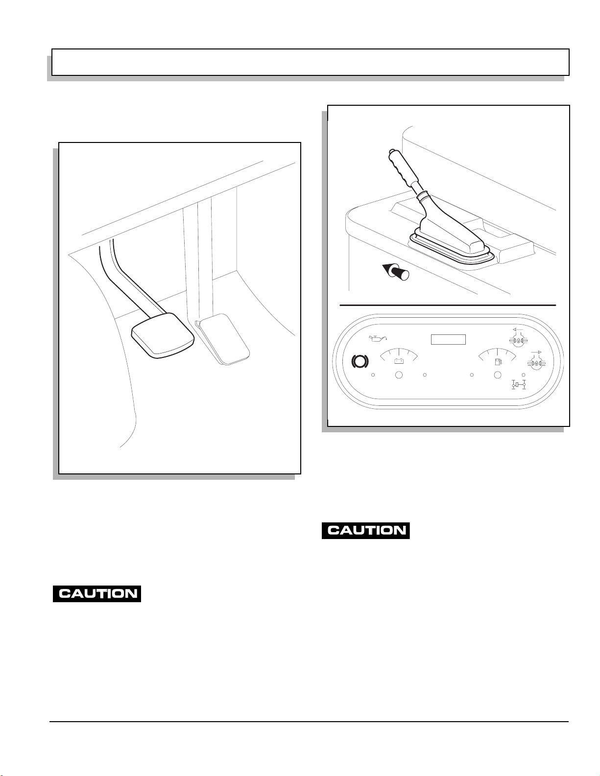
SERVICE BRAKE PEDAL
Front of Vehicle
HOURS
P
Ref Sbp 1
Fig. 2 Service Brake Pedal
The service brake is a hydraulic front disc/rear drum
brake system.
Push foot operated service brake pedal to activate wheel
brakes, slowing or stopping vehic le (Ref. Fig. 2 on page
3).
PARKING BRAKE
Drive vehicle with park brake fully
released. Failure to do so will prema-
turely wear rear brakes.
The park brake is a mechanical system using rear drum
service brakes.
To engage, pull park brake handle up. An indicator light
will illuminate in gauge cluster reminding operator to
release park brake before driving (Ref. Fig. 3 on page 3).
To disengage, pull up slightly and push in release button
at end of handle, then fully lower park brake handle.
Ref Pbh 2
Fig. 3 Park Brake and Indicator
CHOKE
Starting a cold engine may require use of choke. To use,
pull choke knob out and hold while starting engine (Ref.
Fig. 4 on page 4). Once started and engine begins to
warm, release choke knob.
Do not allow starter to operate continu-
ously for more than 10 seconds. Allow
30 seconds between starting attempts. If vehicle does not start
on third attempt, turn key switch off, set park brake and determine cause of problem.
IGNITION SWITCH
Ignition switch has three positions: ‘OFF’, ‘ON’ and
‘START’ (Ref. Fig. 5 on page 4).
Insert key into switch and turn clockwise to ‘ON’ to
enable starting system.
Continue to turn clockwise to “START” to activate starter.
Once engine starts, release key allowing return to ‘ON’.
To prevent inadvertent operation of vehicle when left
unattended, turn key to ‘OFF’ position and remove key.
Owner’s Manual and Service Guide
Page 3

OPERATION AND SERVICE INFORMATION
R
Read all of manual to become thoroughly familiar with this vehicle. Pay particular attention to all Notes, Cautions and Warnings
Choke
Pull
Out
ef Chk 4
Fig. 4 Choke
If
vehicle is equipped with factory installed cus-
tom accessories, some accessories remain
operational with key switch in ‘OFF’ position.
To prevent draining the battery, always
place differential lock switches in the
‘unlocked’ position, turn the key switch to ‘off’ and remove the
key.
If one or both of the differential locks is engaged and the
key left in the ‘on’ position, the differential lock solenoid(s) will be activated (Ref. Fig. 6 on page 4) and (Ref.
Fig. 8 on page 5). Over time the solenoids will drain the
battery to a point where the vehicle will be unable to be
started.
Ref Kes 5
OFF
ON
START
73767G01
Fig. 5 Ignition Switch
Forward Engaged
DIRECTION SELECTOR
73777G01
To reduce possibility of drivetrain dam-
age, vehicle must completely stop
before moving direction selector (Ref. Fig. 6 on page 4).
Reverse
Ref Dsl 5
Neutral Disengaged
Direction selector offers choice of three positions: forward, neutral and reverse (Ref. Fig. 6 on page 4).
Selector must be in neutral to start engine.
Fig. 6 Direction Selector and Differenti al Locks
Always bring vehicle to a complete stop before changing
selection.
Page 4
Owner’s Manual and Service Guide