

Page 1

OWNER’S G UIDE
Page 2

WELCOME
Thank you for purchasing this vehicle. Before driving the vehicle, we ask you to spend some time reading this
Owner’s Guide. This guide contains the information that will assist you in maintaining this highly reliable
vehicle. Some illustrations may show items that are optional for your vehicle. This guide covers the operation
of several vehicles; therefore, some illustrations may not represent your vehicle. Physical differences in
controls will be illustrated.
Most of the service procedures in this guide can be accomplished using common, automotive hand tools.
Contact your service representative on servicing the vehicle in accordance with the Periodic Service
Schedule.
Service Parts Manuals, as well as Repair and Service Manuals, are available from a local Distributor, an
authorized Branch, Genuine E-Z-GO Parts & Accessories Department or at www.shopezgo.com. When
ordering parts or requesting information for your vehicle, provide the vehicle model and VIN.
The following information is needed when contacting E-Z-GO concerning service or parts for your vehicle:
VIN_____________________________________________________________________________________
Vehicle Model ____________________________________________________________________________
Manufacturing Date Code __________________________________________________________________
E-Z-GO 2Five is a motor vehicle that can only be operated by a licensed driver, and must be driven in
accordance with all State traffic laws and the insurance requirements for motor vehicles.
Page 3

FOREWORD
2Five OWNER’S GUIDE
ELECTRIC POWERED
LOW-SPEED VEHICLE
2Five TWO-PASSENGER
2Five FOUR-PASSENGER
STARTING MODEL YEAR 2010
ISSUED JUNE 2009 REVISED MARCH 2013
2Five Owner’s Guide
610598
i
Page 4

FOREWORD
Read all of this manual to become thoroughly familiar with this vehicle. Pay particular attention to all Notices, Cautions, Warnings, and Dangers.
E-Z-GO Division of TEXTRON Inc. reserves the right to incorporate engineering and design changes to products in this Manual, without
obligation to include these changes on units leased/sold previously.
The information contained in this Manual may be revised periodically by E-Z-GO, and therefore is subject to change without notice.
E-Z-GO DISCLAIMS LIABILITY FOR ERRORS IN THIS MANUAL, and E-Z-GO SPECIFICALLY DISCLAIMS LIABILITY FOR INCIDENTAL
AND CONSEQUENTIAL DAMAGES resulting from the use of the information and materials in this Manual.
TO CONTACT US
NORTH AMERICA:
TECHNICAL ASSISTANCE & WARRANTY GENUINE E-Z-GO PARTS & ACCESSORIES
PHONE: 1-800-774-3946 PHONE: 1-888-GET-EZGO (1-888-438-3946)
FAX: 1-800-448-8124 FAX: 1-800-752-6175
INTERNATIONAL:
SALES PHONE: 001-706-798-4311
FAX: 001-706-771-4609
This vehicle is covered by one or more of the following U. S. patents:
7,267,388 / 7,270,363 / 7,332,881 / 7,392,997 / 7,416,238 / D539,702 / D542,723 / D546,271 / D548,661 / D548,991 /
D552,508 / D554.574 / D558,641 / D562,743 / D562,744
E-Z-GO DIVISION OF TEXTRON INC.
1451 MARVIN GRIFFIN ROAD, AUGUSTA, GEORGIA 30906-3852, USA
ii
2Five Owner’s Guide
Page 5

FOREWORD
Read all of this manual to become thoroughly familiar with this vehicle. Pay particular attention to all Notices, Cautions, Warnings, and Dangers.
This vehicle has been designed and manufactured in the United States of America (USA). The Standards and Specifications listed in the following text originate in the USA unless otherwise indicated.
The use of non-Original Equipment Manufacturer (OEM) approved parts may void the warranty.
Overfilling batteries may void the warranty.
BATTERY PROLONGED STORAGE
All batteries will self-discharge over time. The rate of self-discharge varies depending on the ambient
temperature and the age and condition of the batteries.
A fully charged battery will not freeze in winter temperatures unless the temperature falls below
-75° F (-60° C).
For winter storage, the batteries must be clean, fully charged and disconnected from any source of
electrical drain.
The batteries must be checked and recharged as required or at a minimum of 30 day intervals.
2Five Owner’s Guide
iii
Page 6

FOREWORD
Read all of this manual to become thoroughly familiar with this vehicle. Pay particular attention to all Notices, Cautions, Warnings, and Dangers.
Notes:
iv
2Five Owner’s Guide
Page 7

TABLE OF CONTENTS
TITLE PAGE NO.
SAFETY INFORMATION SECTION ................................................................................................... 1
GENERAL SPECIFICATIONS SECTION ......................................................................................... 23
INTRODUCTION SECTION .............................................................................................................. 35
OPERATING PROCEDURES SECTION .......................................................................................... 53
MAINTENANCE PROCEDURES SECTION..................................................................................... 71
REGISTRATION AND WARRANTY ............................................................................................... 113
2Five Owner’s Guide v
Page 8

TABLE OF CONTENTS
Read all of this manual to become thoroughly familiar with this vehicle. Pay particular attention to all Notices, Cautions, Warnings, and Dangers.
Notes:
vi 2Five Owner’s Guide
Page 9

SAFETY INFORMATION
TABLE OF CONTENTS FOR SAFETY INFORMATION SECTION
TITLE PAGE NO.
GENERAL ................................................................................................................................................................................... 3
NOTICES, CAUTIONS, WARNINGS, AND DANGERS.............................................................................................................. 4
GENERAL OPERATION ............................................................................................................................................................. 8
MAINTENANCE ....................................................................................................................................................................... 13
VENTILATION........................................................................................................................................................................... 14
SEAT BELTS............................................................................................................................................................................. 15
Seat Belt Operation ........................................................................................................................................................ 17
REPORTING SAFETY DEFECTS ............................................................................................................................................ 18
LABELS AND PICTOGRAMS ................................................................................................................................................... 19
2Five Owner’s Guide 1
Page 10

SAFETY INFORMATION
Read all of this manual to become thoroughly familiar with this vehicle. Pay particular attention to all Notices, Cautions, Warnings, and Dangers.
Notes:
2 2Five Owner’s Guide
Page 11

SAFETY INFORMATION
Read all of this manual to become thoroughly familiar with this vehicle. Pay particular attention to all Notices, Cautions, Warnings, and Dangers.
GENERAL
For any questions on material contained in this manual, contact an authorized representative for clarification.
Read all labels located on the vehicle. Always replace any damaged or missing labels.
On steep hills it is possible for vehicles to coast at greater speeds. To prevent loss of vehicle control and
possible serious injury, speeds should be limited to no more than 25 mph.
Catastrophic damage to the drivetrain components due to excessive speed may result from driving the
vehicle above 25 mph. Damage caused by excessive speed may cause a loss of vehicle control, is costly, is
considered abuse, and will not be covered under warranty.
2Five Owner’s Guide 3
Page 12

SAFETY INFORMATION
DANGER
Read all of this manual to become thoroughly familiar with this vehicle. Pay particular attention to all Notices, Cautions, Warnings, and Dangers.
NOTICES, CAUTIONS, WARNINGS, AND DANGERS
Throughout this guide NOTICE, CAUTION, WARNING, and DANGER will be used. Please observe these
NOTICES, CAUTIONS, WARNINGS, and DANGERS; be aware that servicing a vehicle requires mechanical
skill and a regard for conditions that could be hazardous. Improper service or repair may damage the vehicle
or render it unsafe.
Address practices not related to personal injury.
Indicates a hazardous situation which, if not avoided, could result in minor or moderate injury.
Indicates a hazardous situation which, if not avoided, could result in death or
serious injury.
Indicates a hazardous situation which, if not avoided, will result in death or
serious injury.
4 2Five Owner’s Guide
Page 13

SAFETY INFORMATION
Read all of this manual to become thoroughly familiar with this vehicle. Pay particular attention to all Notices, Cautions, Warnings, and Dangers.
This manual has been designed to assist in maintaining the vehicle in accordance with procedures developed
by the manufacturer. Adherence to these procedures and troubleshooting tips will ensure the best possible
service from the product. To reduce the chance of personal injury or property damage, the following must be
carefully observed:
THE E-Z-GO 2Five SHALL BE OPERATED ONLY BY PERSONS WITH VALID DRIVERS LICENSES,
AND IN ACCORDANCE WITH APPLICABLE STATE REQUIREMENTS. THIS IS A LEGAL
REQUIREMENT AND IS IMPORTANT TO THE SAFE USE AND OPERATION OF THE PRODUCT.
All customers should adhere to this SAFETY RESTRICTION, in connection with the use of all E-Z-GO
products, new and used, in personal transportation applications.
Federal Low-Speed Vehicle Standard (FMVSS 571.500) can be obtained at Title 49 of the Code of Federal
Regulations, section 571.500, or through the Internet at the website for the U.S. Department of
Transportation - at Dockets and Regulation, then to Title 49 of the Code of Federal Regulations
(Transportation).
All vehicles can be used for a variety of tasks often beyond the original intended use of the vehicle; therefore,
it is impossible to anticipate and warn against every possible combination of circumstances that may occur.
No warning can replace good common sense and prudent driving practices.
2Five Owner’s Guide 5
Page 14

SAFETY INFORMATION
Read all of this manual to become thoroughly familiar with this vehicle. Pay particular attention to all Notices, Cautions, Warnings, and Dangers.
Good common sense and prudent driving practices do more to prevent accidents and injury than all warnings
and instructions combined. E-Z-GO strongly suggests that all users and maintenance personnel read this
entire manual paying particular attention to the CAUTIONS, WARNINGS, and DANGERS contained therein.
If you have any questions regarding this vehicle, contact your authorized E-Z-GO 2Five dealer or write to the
address on the back cover of this publication, Attention: Customer Quality Department.
E-Z-GO reserves the right to make design changes without obligation to make these changes on units
previously sold. The information contained in this manual is subject to change without notice.
E-Z-GO IS NOT LIABLE FOR ERRORS IN THIS MANUAL. E-Z-GO IS NOT LIABLE FOR INCIDENTAL OR
CONSEQUENTIAL DAMAGES THAT RESULT FROM THE USE OF, AND THE RELIANCE ON, THE
MATERIAL IN THIS MANUAL.
This vehicle is designed and manufactured in accordance with FMVSS 571.500.
Be sure that all electrical accessories are grounded directly to the battery (-) post. Never use the chassis or
body as a ground connection.
Refer to GENERAL SPECIFICATIONS for vehicle seating capacity.
6 2Five Owner’s Guide
Page 15

SAFETY INFORMATION
Read all of this manual to become thoroughly familiar with this vehicle. Pay particular attention to all Notices, Cautions, Warnings, and Dangers.
Never modify the vehicle in any way that will alter the weight distribution
of the vehicle, decrease its stability, or increase the speed or extend the stopping
distance beyond the factory specification. Such modifications can result in
serious personal injury or death.
Do not make any such modifications or changes. E-Z-GO prohibits and disclaims responsibility for all such
modifications and alterations, which would adversely affect the safety of the vehicle.
Vehicles that are capable of higher speeds must limit their speed to no more than the speed of other vehicles
when used in a golf course environment. Additionally, speed should be further moderated by the
environmental conditions, terrain, and common sense.
2Five Owner’s Guide 7
Page 16

SAFETY INFORMATION
Read all of this manual to become thoroughly familiar with this vehicle. Pay particular attention to all Notices, Cautions, Warnings, and Dangers.
GENERAL OPERATION
Read the following warnings before attempting to operate the vehicle
:
To prevent personal injury or death, observe the following:
When vehicle is to be left unattended, turn key to OFF position AND REMOVE KEY.
Drive vehicle only as fast as terrain and safety considerations allow. Consider the
terrain and traffic conditions. Consider environmental factors which affect the
terrain and the ability to control the vehicle.
Avoid driving fast downhill. Sudden stops or change of direction may result in a
loss of control. Use brake to control speed when traveling down an incline.
Use extra care and reduced speed when driving in poor driving conditions or on
poor surfaces.
8 2Five Owner’s Guide
Page 17

SAFETY INFORMATION
Read all of this manual to become thoroughly familiar with this vehicle. Pay particular attention to all Notices, Cautions, Warnings, and Dangers.
Stay in designated areas where provided and avoid steep slopes.
Seat belts must be worn at all times while operating the vehicle.
Keep feet, legs, hands, and arms inside vehicle at all times.
Avoid extremely rough terrain.
Check area behind the vehicle before operating in reverse.
Make sure the direction selector is in correct position before depressing the
accelerator pedal.
Slow down before and during turns.
Always bring vehicle to a complete stop before shifting the direction selector.
See GENERAL SPECIFICATIONS for vehicle load and seating capacity.
2Five Owner’s Guide 9
Page 18

SAFETY INFORMATION
Read all of this manual to become thoroughly familiar with this vehicle. Pay particular attention to all Notices, Cautions, Warnings, and Dangers.
Read the following text and warnings before attempting to service vehicle:
In any product, components may eventually fail to perform properly as the result of normal use, age, wear, or
abuse.
It is impossible to anticipate all possible component failures or the manner in which each component may fail.
A vehicle requiring repair is no longer functioning as designed and therefore could be potentially hazardous.
Therefore, use extreme care when working on any vehicle. When diagnosing, removing, or replacing any
components that are not operating correctly, take time to consider the safety of yourself and others around
you.
Some components are heavy, spring-loaded, highly corrosive, explosive, may produce high amperage, or
reach high temperatures. Exposure to battery acid and hydrogen gas could result in serious bodily injury. Be
careful to protect hands, face, feet, and body from injury.
Always use the appropriate tools listed in the tool list and wear approved safety equipment.
10 2Five Owner’s Guide
Page 19

SAFETY INFORMATION
Read all of this manual to become thoroughly familiar with this vehicle. Pay particular attention to all Notices, Cautions, Warnings, and Dangers.
.
Before working on the vehicle, remove all jewelry.
Be sure no loose clothing or hair can contact moving parts.
Use care not to touch hot objects.
Wear eye protection when working on or around the vehicle. In particular, use care
when working around batteries, using solvents or compressed air.
Hydrogen gas is formed when charging batteries. Do not charge batteries without
adequate ventilation.
Do not permit open flame or anyone to smoke in an area that is being used for
charging batteries.
2Five Owner’s Guide 11
Page 20

SAFETY INFORMATION
Read all of this manual to become thoroughly familiar with this vehicle. Pay particular attention to all Notices, Cautions, Warnings, and Dangers.
ALWAYS:
• use the vehicle in a responsible manner and maintain the vehicle in safe operating condition
• read and observe all warnings and operation instruction labels affixed to the vehicle
• use extreme caution in areas where pedestrians are present
• maintain adequate distance between vehicles
• follow all safety rules established in the area where the vehicle is being operated
• reduce speed to compensate for poor terrain or conditions
• apply brake to control speed on steep grades
• reduce speed in wet areas
• use extreme caution when approaching sharp or blind turns
• use extreme caution when driving over loose terrain
12 2Five Owner’s Guide
Page 21

SAFETY INFORMATION
Read all of this manual to become thoroughly familiar with this vehicle. Pay particular attention to all Notices, Cautions, Warnings, and Dangers.
MAINTENANCE
ALWAYS:
• replace damaged or missing warning, caution, or information labels
• maintain the vehicle in accordance with the manufacturer’s periodic service schedule
• ensure that repairs are only performed by trained and qualified personnel
• follow the manufacturer’s maintenance procedures
• insulate any tools used within the battery area in order to prevent sparks or battery explosion
• use specified replacement parts. Never use replacement parts of lesser quality
• use recommended tools
• maintain the vehicle in an area away from exposed flame or persons who are smoking
• test drive the vehicle after all repairs or maintenance in a safe area that is free of both vehicular and
pedestrian traffic
• keep complete records of the maintenance history of the vehicle
2Five Owner’s Guide 13
Page 22

SAFETY INFORMATION
Read all of this manual to become thoroughly familiar with this vehicle. Pay particular attention to all Notices, Cautions, Warnings, and Dangers.
VENTILATION
ALWAYS:
• charge the vehicle in a well-ventilated area
• charge in an area free of flammable liquids and items
• charge a vehicle in an area that is free from flame or spark, pay particular attention to natural gas or
propane water heaters and furnaces.
• use a dedicated 15-amp circuit for each battery charger, DO NOT permit other appliances to be plugged
into the receptacle when the charger is in operation.
• operate the charger in accordance with E-Z-GO’s recommendations or applicable electrical codes
14 2Five Owner’s Guide
Page 23

SAFETY INFORMATION
Read all of this manual to become thoroughly familiar with this vehicle. Pay particular attention to all Notices, Cautions, Warnings, and Dangers.
SEAT BELTS
Always operate the vehicle with seat belts properly fastened.
Be certain the seat belts are latched securely and are free from twists.
Position the shoulder belt across the top of the shoulder. Do not place the
shoulder belt under an arm.
Loose fitting safety belts significantly reduce protection. Keep belts snug and
positioned low on the hips.
Do not exceed the recommended number of occupants for the vehicle;
Bucket seats are designed for one occupant only.
Bench seats are designed for two occupants only.
2Five Owner’s Guide 15
Page 24

SAFETY INFORMATION
Read all of this manual to become thoroughly familiar with this vehicle. Pay particular attention to all Notices, Cautions, Warnings, and Dangers.
The driver and all passengers must wear seat belts, one person per belt.
The two-passenger 2Five has two bucket seats and is equipped with two safety belts, one for the driver and
one for the passenger. The four-passenger 2Five has a rear-facing bench seat with two additional
passenger seat belts. The safety belts must be used at all times while operating the vehicle.
This vehicle has not been tested for use with automotive style child safety seats or booster seats.
Do not use automotive style child safety seats or booster seats with this vehicle.
Inspect the safety belt webbing and hardware periodically. Check for cuts, frays or loose parts. Replace
components if excessive wear or damage is noticed.
Keep safety belts clean and dry. To clean, use mild soap and warm water. Do not use bleach, dye or
abrasive cleaners as this will weaken the belt webbing material.
Do not insert any foreign objects into the retractor mechanism.
Periodically check for smooth operation and replace if the mechanism is not operating properly.
Pregnant, disabled, or injured persons should consult their doctor for specific recommendations before
using the 2Five.
16 2Five Owner’s Guide
Page 25

SAFETY INFORMATION
Read all of this manual to become thoroughly familiar with this vehicle. Pay particular attention to all Notices, Cautions, Warnings, and Dangers.
Seat Belt Operation
To properly secure the seat belts, pull the metal tab out away from the retractor and insert into the appropriate
buckle located near the center of the seat. A click will be heard when the tab is securely latched. Position the
lap belt as low as possible on the hips, not the waist. Properly adjust and ensure a snug fit by pulling the
shoulder portion upward.
The retractor will lock the belt during sudden stops. It may also lock if the person leans forward too quickly.
Slow, easy motions will allow for free travel.
To release the safety belt, press the buckle release button and allow the belt to retract. If the belt does not
retract, check for twists.
2Five Owner’s Guide 17
Page 26

SAFETY INFORMATION
Read all of this manual to become thoroughly familiar with this vehicle. Pay particular attention to all Notices, Cautions, Warnings, and Dangers.
REPORTING SAFETY DEFECTS
If you believe that your vehicle has a defect which could cause a crash or could cause injury or death, you
should immediately inform the National Highway Traffic Safety Administration (NHTSA) in addition to notifying
E-Z-GO Division of Textron Inc.
If NHTSA receives similar complaints, it may open an investigation, and if it finds that a safety defect exists in
a group of vehicles, it may order a recall and remedy campaign. However, NHTSA cannot become involved in
individual problems between you, your dealer, or E-Z-GO Division of Textron Inc.
To contact NHTSA, you may call the Vehicle Safety Hotline toll-free at 1-888-327-4236 (TTY: 1-800-424-
9153); go to http://nhtsa.safercar.gov; or write to:
Administrator, NHTSA
1200 New Jersey Avenue SE
Washington, DC 20590
You can also obtain other information about motor vehicle safety from http://www.safercar.gov
18 2Five Owner’s Guide
Page 27
SAFETY INFORMATION
Read all of this manual to become thoroughly familiar with this vehicle. Pay particular attention to all Notices, Cautions, Warnings, and Dangers.
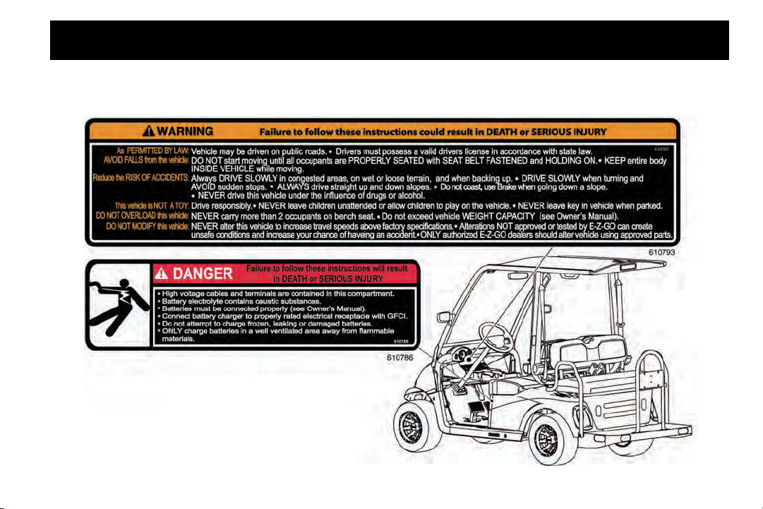
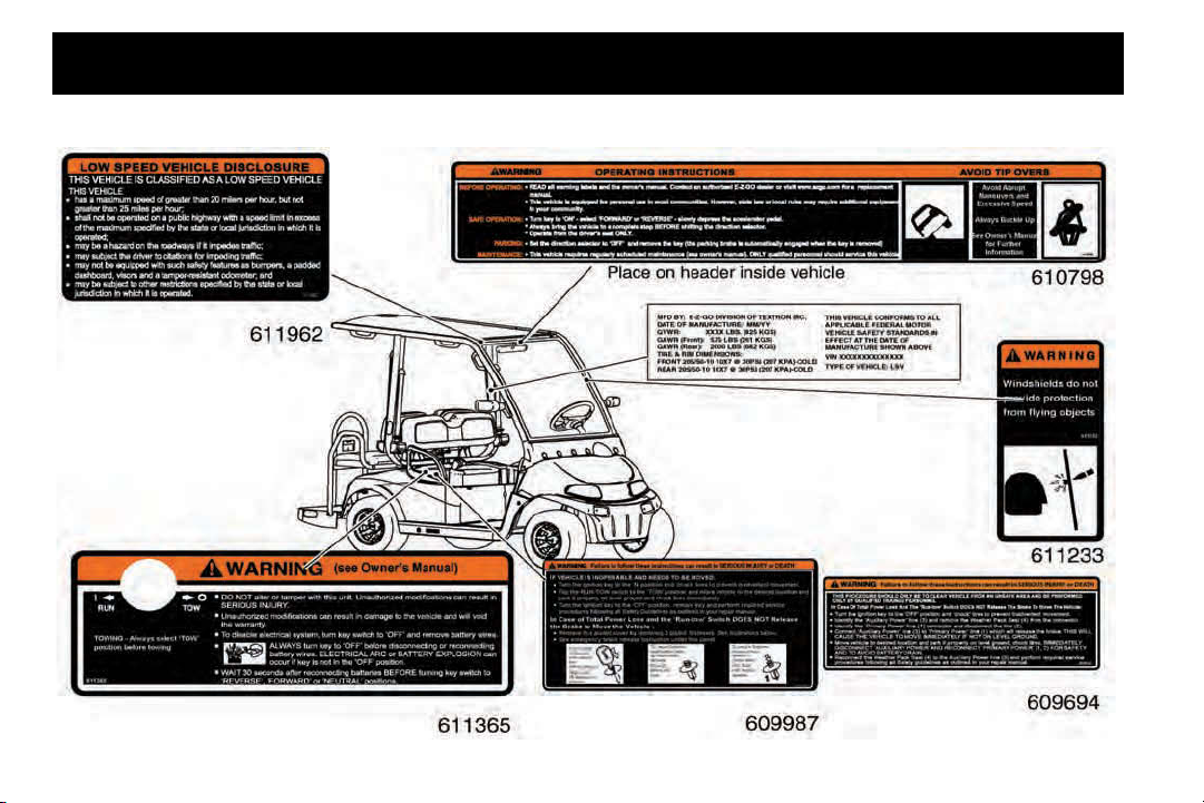
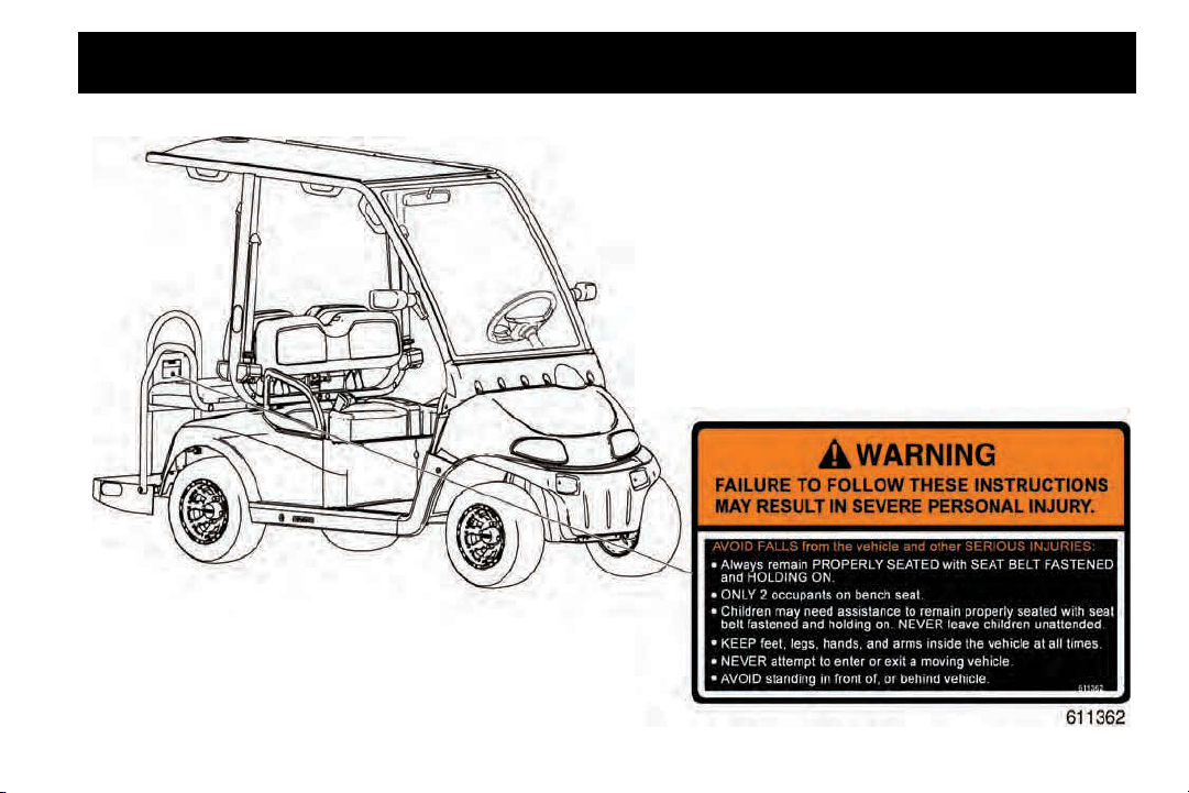
LABELS AND PICTOGRAMS
2Five Owner’s Guide 19
Page 28
SAFETY INFORMATION
Read all of this manual to become thoroughly familiar with this vehicle. Pay particular attention to all Notices, Cautions, Warnings, and Dangers.
20 2Five Owner’s Guide
Page 29
SAFETY INFORMATION
Read all of this manual to become thoroughly familiar with this vehicle. Pay particular attention to all Notices, Cautions, Warnings, and Dangers.
2Five Owner’s Guide 21
Page 30

SAFETY INFORMATION
Read all of this manual to become thoroughly familiar with this vehicle. Pay particular attention to all Notices, Cautions, Warnings, and Dangers.
Notes:
22 2Five Owner’s Guide
Page 31

GENERAL SPECIFICATIONS
TABLE OF CONTENTS FOR GENERAL SPECIFICATIONS SECTION
TITLE PAGE NO.
2Five TWO-PASSENGER SPECIFICATIONS.......................................................................................................................... 25
2Five FOUR-PASSENGER SPECIFICATIONS........................................................................................................................ 27
2Five Owner’s Guide 23
Page 32

GENERAL SPECIFICATIONS
Read all of this manual to become thoroughly familiar with this vehicle. Pay particular attention to all Notices, Cautions, Warnings, and Dangers.
Notes:
24 2Five Owner’s Guide
Page 33

GENERAL SPECIFICATIONS
Read all of this manual to become thoroughly familiar with this vehicle. Pay particular attention to all Notices, Cautions, Warnings, and Dangers.
2Five TWO-PASSENGER SPECIFICATIONS
BATTERIES Four 12 Volt deep cycle (70 minute minimum, 150 Amp-Hour discharge rate)
SPEED CONTROLLER Solid state, 235 amp capacity
MOTOR 3 phase AC induction
TRANSAXLE 14.76:1 Reverse helical geared with input pinion splined to the motor shaft
BRAKES 4 Wheel hydraulic disc
PARKING BRAKE Automatic parking brake function
FRONT SUSPENSION Coil springs over hydraulic shock absorbers
REAR SUSPENSION Leaf springs with hydraulic shock absorbers
STEERING Single reduction rack and pinion
STEERING WHEEL Dual handgrips with textured rubber overmold
SEATING Split bench, foam cushion with vinyl cover and hip restraints/hand holds
SEATING CAPACITY Operator and one passenger
TOTAL LOAD CAPACITY 800 lbs. (363 kg) including operator, passenger, accessories and cargo
SPEED Up to 25 mph (40 kph) in forward
CHASSIS Welded tubular steel, powder coated (DuraShield™)
2Five Owner’s Guide 25
Page 34

GENERAL SPECIFICATIONS
Read all of this manual to become thoroughly familiar with this vehicle. Pay particular attention to all Notices, Cautions, Warnings, and Dangers.
BODY Flexible, impact-resistant, injection-molded TPO (Thermoplastic Polyolefin) with
Base Coat / Clear Coat
DASH PANEL Scuff-resistant plastic with four drink holders, storage, and 12-volt receptacle for
accessories
TIRES 205/50-10**
TIRE PRESSURE 30 psi (207 kPa)**
GROUND CLEARANCE 4.7 inches (11.9 cm) at differential
WEIGHT 822 lbs (373 kg) without batteries
OPERATING CONTROLS &
INSTRUMENTATION
LIGHTS Headlights, taillights, brake lights, turn signal/hazard light
BATTERY CHARGER
WITH
DC TO DC CONVERTER
** DO NOT use low inflation pressure tires on any E-Z-GO vehicle. DO NOT use any tire which has a recommended inflation pressure
less than the inflation pressure recommended in the Owner’s Guide.
Removable key, ’deadman’ accelerator control, speedometer/odometer, horn,
rabbit/turtle speed control switch, direction selector, audible reverse warning, state
of charge meter
On-board battery charger with anti-drive away interlock and integrated 48-volt to
12-volt DC to DC converter with 30-amp output for accessories. Charger will
accept 110-230 VAC input, charging the batteries with 48-volt DC, 13-amp output.
Charger is UL Listed and CSA Certified
26 2Five Owner’s Guide
Page 35

GENERAL SPECIFICATIONS
Read all of this manual to become thoroughly familiar with this vehicle. Pay particular attention to all Notices, Cautions, Warnings, and Dangers.
2Five FOUR-PASSENGER SPECIFICATIONS
BATTERIES Four 12 Volt deep cycle (70 minute minimum, 150 Amp-Hour discharge rate)
SPEED CONTROLLER Solid state, 235 amp capacity
MOTOR 3 phase AC induction
TRANSAXLE 14.76:1 Reverse helical geared with input pinion splined to the motor shaft
BRAKES 4 Wheel hydraulic disc
PARKING BRAKE Automatic parking brake function
FRONT SUSPENSION Coil springs over hydraulic shock absorbers
REAR SUSPENSION Leaf springs with hydraulic shock absorbers
STEERING Single reduction rack and pinion
STEERING WHEEL Dual handgrips with textured rubber overmold
SEATING Front: Split bench foam cushion with vinyl cover and hip restraints/hand holds
Rear: Bench-style foam cushion with vinyl cover and hip restraints/hand holds
SEATING CAPACITY Operator and three passengers
TOTAL LOAD CAPACITY 800 lbs. (363 kg) including operator, passengers, accessories and cargo
SPEED Up to 25 mph (40 kph) in forward
CHASSIS Welded tubular steel, powder coated (DuraShield™)
2Five Owner’s Guide 27
Page 36

GENERAL SPECIFICATIONS
Read all of this manual to become thoroughly familiar with this vehicle. Pay particular attention to all Notices, Cautions, Warnings, and Dangers.
BODY Flexible, impact-resistant, injection-molded TPO (Thermoplastic Polyolefin) with
Base Coat / Clear Coat
DASH PANEL Scuff-resistant plastic with four drink holders, storage, and 12-volt receptacle for
accessories
TIRES 205/50-10**
TIRE PRESSURE 30 psi (207 kPa)**
GROUND CLEARANCE 4.5 inches (11.4 cm) at differential
WEIGHT 872 lbs (397 kg) without batteries
OPERATING CONTROLS &
INSTRUMENTATION
LIGHTS Headlights, taillights, brake lights, turn signal/hazard light
BATTERY CHARGER
WITH
DC to DC CONVERTER
** DO NOT use low inflation pressure tires on any E-Z-GO vehicle. DO NOT use any tire which has a recommended inflation pressure
less than the inflation pressure recommended in the Owner’s Guide.
Removable key, ’deadman’ accelerator control, speedometer/odometer, horn,
rabbit/turtle speed control switch, direction selector, audible reverse warning, state
of charge meter
On-board battery charger with anti-drive away interlock and integrated 48-volt to
12-volt DC to DC converter with 30-amp output for accessories. Charger will
accept 110-230 VAC input, charging the batteries with 48-volt DC, 13-amp output.
Charger is UL Listed and CSA Certified
28 2Five Owner’s Guide
Page 37

GENERAL SPECIFICATIONS
Read all of this manual to become thoroughly familiar with this vehicle. Pay particular attention to all Notices, Cautions, Warnings, and Dangers.
Fig. 1 2Five Two-Passenger Dimensions
2Five Owner’s Guide 29
Page 38

GENERAL SPECIFICATIONS
Read all of this manual to become thoroughly familiar with this vehicle. Pay particular attention to all Notices, Cautions, Warnings, and Dangers.
Fig. 2 2Five Four-Passenger Dimensions
30 2Five Owner’s Guide
Page 39

GENERAL SPECIFICATIONS
Read all of this manual to become thoroughly familiar with this vehicle. Pay particular attention to all Notices, Cautions, Warnings, and Dangers.
Fig. 3 2Five Two- and Four-Passenger Dimensions
2Five Owner’s Guide 31
Page 40

GENERAL SPECIFICATIONS
Read all of this manual to become thoroughly familiar with this vehicle. Pay particular attention to all Notices, Cautions, Warnings, and Dangers.
Fig. 4 2Five Two- and Four-Passenger Dimensions
32 2Five Owner’s Guide
Page 41

GENERAL SPECIFICATIONS
19.7 ft
(6.0 m)
MAX RAMP GRADE 25% OR 14°
MAX SIDE TILT 25% OR 14°
Read all of this manual to become thoroughly familiar with this vehicle. Pay particular attention to all Notices, Cautions, Warnings, and Dangers.
Fig. 5 Vehicle Incline Specifications and Turning Diameter
2Five Owner’s Guide 33
Page 42

GENERAL SPECIFICATIONS
Read all of this manual to become thoroughly familiar with this vehicle. Pay particular attention to all Notices, Cautions, Warnings, and Dangers.
Notes:
34 2Five Owner’s Guide
Page 43

INTRODUCTION
TABLE OF CONTENTS FOR INTRODUCTION SECTION
TITLE PAGE NO.
FEATURES ............................................................................................................................................................................... 37
General Information........................................................................................................................................................ 37
Parking Brake ................................................................................................................................................................. 38
Key Switch/Direction Selector ........................................................................................................................................ 41
High/Low Speed Switch.................................................................................................................................................. 41
Accelerator Pedal ........................................................................................................................................................... 41
Brake Pedal.................................................................................................................................................................... 41
Horn................................................................................................................................................................................ 41
Headlight Switch............................................................................................................................................................. 43
State of Charge Meter .................................................................................................................................................... 43
Speedometer .................................................................................................................................................................. 43
Odometer........................................................................................................................................................................ 43
12V Accessory Plug ....................................................................................................................................................... 43
Steering Wheel............................................................................................................................................................... 45
Turn Signal/Hazard Switch ............................................................................................................................................. 45
Rear View Mirror............................................................................................................................................................. 45
Side View Mirrors ........................................................................................................................................................... 45
Windshield Wiper Switch (optional) ................................................................................................................................ 45
2Five Owner’s Guide 35
Page 44

INTRODUCTION
Locking Glovebox (optional) ........................................................................................................................................... 45
Cup Holder...................................................................................................................................................................... 45
Front Seats ..................................................................................................................................................................... 47
Hip Restraint - Front........................................................................................................................................................ 47
Grab Handles - Front Passenger .................................................................................................................................... 47
Seat Belts - Front ............................................................................................................................................................ 47
Windshield Wiper (if equipped) ....................................................................................................................................... 47
Headlamps...................................................................................................................................................................... 47
Front Turn Signals .......................................................................................................................................................... 47
Rear Seat........................................................................................................................................................................ 49
Seat Belts - Rear............................................................................................................................................................. 49
Rear Restraints............................................................................................................................................................... 49
Grab Handles - Rear Passenger..................................................................................................................................... 49
Brake Light/Turn Signal .................................................................................................................................................. 49
Brake Light (Overhead)................................................................................................................................................... 49
Rear Storage Compartment Release Handle .................................................................................................................49
License Plate Holder....................................................................................................................................................... 49
On-board Charger with DC to DC Converter ..................................................................................................................51
On-board Charger Receptacle........................................................................................................................................ 51
Brake Master Cylinder .................................................................................................................................................... 51
Battery Compartment...................................................................................................................................................... 51
Run/Tow Switch .............................................................................................................................................................. 51
36 2Five Owner’s Guide
Page 45

INTRODUCTION
Read all of this manual to become thoroughly familiar with this vehicle. Pay particular attention to all Notices, Cautions, Warnings, and Dangers.
FEATURES
General Information
If the vehicle is equipped with factory installed custom accessories, some accessories remain operational with the key
switch in the ‘OFF’ position.
ALL accessories that do NOT use the accessory wiring harness MUST
be connected to draw from the entire 48 Volt battery pack. A DC to DC
converter is required for accessories that require voltage other than 48
volts to operate properly.
Accessories connected to this vehicle that do not use the accessory harness must be connected to the DC to DC converter.
2Five Owner’s Guide 37
ATTACH NEGATIVE WIRE
FROM ACCESSORY TO
(-) BATTERY TERMINAL
ATTACH POWER WIRE
FROM ACCESSORY TO
(+) BATTERY TERMINAL
Page 46

INTRODUCTION
Read all of this manual to become thoroughly familiar with this vehicle. Pay particular attention to all Notices, Cautions, Warnings, and Dangers.
Parking Brake
This vehicle is equipped with an automatic parking brake; when the vehicle is stopped the parking brake is
automatically set. The parking brake is released when the key switch/direction selector is in forward (’F’) or
reverse (’R’) and the accelerator is depressed. The parking brake is also released when the Run/Tow switch
is placed in the ’TOW’ position with the key switch turned to neutral (’N’).
38 2Five Owner’s Guide
Page 47

INTRODUCTION
Read all of this manual to become thoroughly familiar with this vehicle. Pay particular attention to all Notices, Cautions, Warnings, and Dangers.
Notes:
2Five Owner’s Guide 39
Page 48

INTRODUCTION
Read all of this manual to become thoroughly familiar with this vehicle. Pay particular attention to all Notices, Cautions, Warnings, and Dangers.
40 2Five Owner’s Guide
Page 49

INTRODUCTION
Read all of this manual to become thoroughly familiar with this vehicle. Pay particular attention to all Notices, Cautions, Warnings, and Dangers.
1. Key Switch/Direction Selector
To reduce the possibility of component damage, the vehicle must be stopped before moving the key
switch/direction selector.
Located on the dash panel, the key switch/direction selector enables the electrical system of the vehicle to be
turned on and off by turning the key; it also functions as the direction selector for forward, neutral or reverse.
To prevent inadvertent operation of the vehicle when left unattended, the key should be turned to the ‘OFF’
position and removed.
2. High/Low Speed Switch
Located above the four-cup console, this switch allows operator to select between High/Rabbit and Low/Turtle speeds for on-road and golf course operation. High/Rabbit allows maximum speed of 25 mph for on-road
use. Low/Turtle allows maximum speed of 14 mph for golf course use.
3. Accelerator Pedal
With the key switch in the ’F’ or ’R’ position, depressing the accelerator pedal starts the motor and will move
the vehicle in the direction indicated on the key switch/direction selector.
4. Brake Pedal
This vehicle is equipped with 4 wheel hydraulic disc brakes; the brake master cylinder is located under the
seat on the driver-side of the vehicle.
5. Horn
The horn button is located on the driver’s side floorboard; depressing the button will sound the vehicle’s horn.
2Five Owner’s Guide 41
Page 50

INTRODUCTION
Read all of this manual to become thoroughly familiar with this vehicle. Pay particular attention to all Notices, Cautions, Warnings, and Dangers.
42 2Five Owner’s Guide
Page 51

INTRODUCTION
Read all of this manual to become thoroughly familiar with this vehicle. Pay particular attention to all Notices, Cautions, Warnings, and Dangers.
6. Headlight Switch
The headlight ON/OFF switch is located on the instrument panel to the left of the speedometer.
7. State of Charge Meter
The vehicle is equipped with a state of charge meter located in the dash panel below the speedometer. The
state of charge meter indicates the amount of usable power in the batteries. The state of charge meter shows
the condition of the battery pack with F indicating a full charge on the battery pack and E indicating the battery
pack needs to be charged.
8. Speedometer
The digital speedometer is located on the dash in front of the steering wheel and indicates vehicle speed.
9. Odometer
The digital odometer is located directly below the speedometer and indicates total miles driven on the vehicle.
The odometer will also display warning or error codes to alert the driver to potential problems with the vehicle.
10. 12V Accessory Plug
The 12-volt accessory plug is located on the center of the dash to the left of the passenger-side glovebox.
The 12-volt accessory plug can be used to run a variety of approved 12-volt accessories. Total current draw
must be 10 amps or less. The accessory plug can be used with the key switch in any position.
2Five Owner’s Guide 43
Page 52

INTRODUCTION
13
11
14
15
12
16
17
Read all of this manual to become thoroughly familiar with this vehicle. Pay particular attention to all Notices, Cautions, Warnings, and Dangers.
44 2Five Owner’s Guide
Page 53

INTRODUCTION
Read all of this manual to become thoroughly familiar with this vehicle. Pay particular attention to all Notices, Cautions, Warnings, and Dangers.
11. Steering Wheel
The steering wheel located in front of the driver seat is used to steer the vehicle. The steering wheel does not
contain an airbag.
12. Turn Signal/Hazard Switch
The switch is mounted on the steering column. To activate the hazard lights, pull the hazard switch away from
the steering column. To deactivate, temporarily flip the turn signal switch in either direction.
13. Rear View Mirror
The rear view mirror is a two-position mirror manually adjusted for day and nighttime conditions.
14. Side View Mirrors
A driver-side mirror is standard, passenger-side is offered as an option. Side view mirrors are manually
adjusted.
15. Windshield Wiper Switch (optional)
The windshield wiper switch is located on the wiper motor cover plate. It is a two-speed rocker switch that has
LOW/HIGH/OFF positions.
16. Locking Glove Box
A passenger-side locking glove box is standard, driver-side is offered as an option. A separate key is used for
the locking glove boxes.
17. Cup Holder
A cup holder is provided for convenience of both the driver and front passenger. No cup holder is available for
rear seat occupants.
2Five Owner’s Guide 45
Page 54

INTRODUCTION
Read all of this manual to become thoroughly familiar with this vehicle. Pay particular attention to all Notices, Cautions, Warnings, and Dangers.
46 2Five Owner’s Guide
Page 55

INTRODUCTION
Read all of this manual to become thoroughly familiar with this vehicle. Pay particular attention to all Notices, Cautions, Warnings, and Dangers.
18. Front Seats
The split bench front seat is designed for one occupant on each side of the center console. There is a seat
belt for the passenger and one for the driver.
19. Hip Restraint - Front
The front hip restraints are designed to help keep the occupants properly positioned in the event of sudden
vehicle position changes.
20. Grab Handles - Front Passenger
The vehicle is equipped with grab handles.
21. Seat Belts - Front
Two seat belts are located for the front seat occupants (driver and passenger).
22. Windshield Wiper (optional)
A two-speed windshield wiper is available as an option.
23. Head Lamps
The vehicle is equipped with two single element head lamps.
24. Front Turn Signals
Vehicle is equipped with front and rear turn signals.
2Five Owner’s Guide 47
Page 56

INTRODUCTION
Read all of this manual to become thoroughly familiar with this vehicle. Pay particular attention to all Notices, Cautions, Warnings, and Dangers.
30
28
26
27
32
31
25
27
29
48 2Five Owner’s Guide
Page 57

INTRODUCTION
Read all of this manual to become thoroughly familiar with this vehicle. Pay particular attention to all Notices, Cautions, Warnings, and Dangers.
25. Rear Seat
The rear seat is for two passengers only.
26. Seat Belts - Rear
Two rear seat belts are provided for the rear seat occupants.
27. Rear Restraints
There are two hip restraints and one hand hold to help keep occupants properly positioned in the event of
sudden vehicle position change.
28. Grab Handles - Rear Passenger
The vehicle is equipped with grab handles.
29. Brake Light/Turn Signal
The combination brake light/turn signal assemblies are located on the rear fenders.
30. Brake Light (Overhead)
The vehicle is equipped with an overhead brake light.
31. Rear Storage Compartment
The rear storage compartment can be accessed by raising the back edge of the rear seat bottom.
32. License Plate Holder
The rear license plate is mounted to the rear crossmember behind the front seats on the two-passenger vehicle. The license plate is mounted to the rear hand hold on the four-passenger vehicle.
2Five Owner’s Guide 49
Page 58

INTRODUCTION
Read all of this manual to become thoroughly familiar with this vehicle. Pay particular attention to all Notices, Cautions, Warnings, and Dangers.
36
38
34
50 2Five Owner’s Guide
33
37
35
Page 59

INTRODUCTION
Read all of this manual to become thoroughly familiar with this vehicle. Pay particular attention to all Notices, Cautions, Warnings, and Dangers.
33. Battery Compartment
The battery compartment can be accessed by raising the front seat to perform battery maintenance and
access the Run/Tow switch.
34. On-board Charger Receptacle
The charging cord is to be connected to this receptacle while the vehicle is being charged.
35. On-board Charger with DC to DC Converter
On-board charger is used to charge battery while vehicle is parked and the DC to DC converter is used to
power accessories.
36. Fuse Block
The Fuse Block is used to provide electrical protection to some accessories and options.
37. Brake Master Cylinder
The Brake Master Cylinder fluid level must be kept between the MIN and MAX lines on the master cylinder.
38. Run/Tow Switch
The Run/Tow switch is used when the vehicle has become stalled or inoperative.
Chock tires before placing the vehicle in neutral and moving Run/Tow to ‘TOW’
position. Vehicle could roll and cause serious injury or death.
2Five Owner’s Guide 51
Page 60

INTRODUCTION
Read all of this manual to become thoroughly familiar with this vehicle. Pay particular attention to all Notices, Cautions, Warnings, and Dangers.
Before attempting to move the vehicle, turn the key switch to ’N’ and move the Run/Tow switch to the
‘TOW’ position. Failure to do so will damage the controller or motor.
The Run/Tow switch should always be returned to the ’RUN-STORAGE’ position after moving a stalled vehicle. If the
switch is left in the ’TOW’ position for an extended period of time, it will drain the batteries.
The Run/Tow switch is located under the seat on the passenger side of the vehicle.
With the switch in the ‘TOW’ position and the key in ’N’:
• the electronic parking brake is deactivated, which allows a stalled vehicle to be moved or roll freely,
except in the event of a controller failure
• the brake is still active
• the reverse warning beeper is deactivated
With the switch in ‘RUN-STORAGE’ position:
• the electronic parking brake is activated and the reverse warning beeper features are activated
52 2Five Owner’s Guide
Page 61

OPERATING PROCEDURES
TABLE OF CONTENTS FOR OPERATING PROCEDURES SECTION
TITLE PAGE NO.
SERIAL NUMBER LOCATION.................................................................................................................................................. 55
VEHICLE IDENTIFICATION NUMBER (VIN) .......................................................................................................................... 57
VEHICLE DATA PLATE ............................................................................................................................................................ 58
BEFORE INITIAL USE .............................................................................................................................................................. 59
ON-BOARD CHARGER ............................................................................................................................................................ 61
Understanding the Charger ............................................................................................................................................ 62
Maintenance Instructions................................................................................................................................................ 64
OPERATING THE VEHICLE..................................................................................................................................................... 65
Regenerative Braking ..................................................................................................................................................... 67
Pedal-Up Braking ........................................................................................................................................................... 67
Parking Brake ................................................................................................................................................................. 68
High Pedal Disable Feature............................................................................................................................................ 68
Starting and Driving ........................................................................................................................................................ 68
Starting Vehicle on a Hill ................................................................................................................................................ 69
Coasting ......................................................................................................................................................................... 69
Labels and Pictograms ................................................................................................................................................... 69
Sun Top and Windshield ................................................................................................................................................ 70
2Five Owner’s Guide 53
Page 62

OPERATING PROCEDURES
Read all of this manual to become thoroughly familiar with this vehicle. Pay particular attention to all Notices, Cautions, Warnings, and Dangers.
Notes:
54 2Five Owner’s Guide
Page 63

Read all of this manual to become thoroughly familiar with this vehicle. Pay particular attention to all Notices, Cautions, Warnings, and Dangers.
Serial Number
SERIAL NUMBER LOCATION
Three serial number and manufacture date code labels are on the vehicle. One is placed on the steering
column (Ref. Fig. 1), the second is located on the frame member under the front splash shield on the driver side (Ref. Fig. 2) and the third is located on the passenger side frame rail at the rear of the vehicle (Ref.
Fig. 3).
In order to obtain correct components for the vehicle, the manufacture date code, serial number and vehicle model must be provided when ordering service parts.
OPERATING PROCEDURES
Fig. 1 Serial Number Location on
Steering Column
2Five Owner’s Guide 55
Page 64

OPERATING PROCEDURES
Serial Number
Serial Number
Read all of this manual to become thoroughly familiar with this vehicle. Pay particular attention to all Notices, Cautions, Warnings, and Dangers.
Fig. 3 Serial Number on Rear Frame
Fig. 2 Serial Number on Front Frame
56 2Five Owner’s Guide
Page 65

OPERATING PROCEDURES
Read all of this manual to become thoroughly familiar with this vehicle. Pay particular attention to all Notices, Cautions, Warnings, and Dangers.
VEHICLE IDENTIFICATION NUMBER (VIN)
The Vehicle Identification Number (VIN) is located on the far left side of the header (Ref. Fig. 4). It may be
necessary to provide the VIN when service or parts are needed for the vehicle. The VIN must not be removed
from the vehicle.
Fig. 4 VIN on Header
2Five Owner’s Guide 57
Page 66

OPERATING PROCEDURES
Read all of this manual to become thoroughly familiar with this vehicle. Pay particular attention to all Notices, Cautions, Warnings, and Dangers.
VEHICLE DATA PLATE
The vehicle data plate is located on the inside surface of the canopy strut (Ref. Fig. 5). The data plate contains information concerning the Date of Manufacture, GVWR, GAWR (Front), GAWR (Rear), Tire and Rim
Dimensions, VIN, and Type of Vehicle.
Fig. 5 Vehicle Data Plate on Header
58 2Five Owner’s Guide
Page 67

OPERATING PROCEDURES
Read all of this manual to become thoroughly familiar with this vehicle. Pay particular attention to all Notices, Cautions, Warnings, and Dangers.
BEFORE INITIAL USE
Read and follow the safety instructions on the cup holder and header. Understanding how to use this vehicle and its accessories is essential to safety and good performance. Maintaining good performance depends to a large extent on the operator.
Hydrogen gas is generated as a natural part of the lead acid battery charging process. A 4% concentration of hydrogen gas is explosive and could cause severe
injury or death. Charging must take place in an area that is adequately ventilated
(minimum of five air exchanges per hour).
To reduce the chance of battery explosion that could result in severe injury or
death, never smoke around or charge batteries in an area that has open flame or
electrical equipment that could cause an electrical arc.
Before a new vehicle is put into operation, the items shown in the INITIAL SERVICE CHART must be performed (Ref. Fig. 6).
The vehicle batteries must be fully charged before initial use.
Check for correct tire inflation. See GENERAL SPECIFICATIONS.
Check fluid level in the brake master cylinder.
Check the operation of the brakes.
2Five Owner’s Guide 59
Page 68

OPERATING PROCEDURES
ITEM SERVICE OPERATION
Batteries Charge batteries
Seats Remove protective plastic covering
Brakes Check master cylinder fluid level & brake operation
Perform brake burnishing procedure
Establish acceptable stopping distance
Tires Check air pressure (see SPECIFICATIONS)
Read all of this manual to become thoroughly familiar with this vehicle. Pay particular attention to all Notices, Cautions, Warnings, and Dangers.
Remove the protective clear plastic from the seat bottom and back rest before placing the vehicle in service.
Fig. 6 Initial Service Chart
BRAKE BURNISHING PROCEDURE:
For new vehicles or after replacement of brake pads or rotors, it is recommended that approximately 20
stops with moderate braking from 20 mph to 5 mph should be made without coming to a complete stop.
This procedure will assure that your new brakes will function to their full potential and maintain maximum
wear resistance.
Determine and record the braking distance required to stop the vehicle for future brake performance tests.
60 2Five Owner’s Guide
Page 69

OPERATING PROCEDURES
DANGER
Read all of this manual to become thoroughly familiar with this vehicle. Pay particular attention to all Notices, Cautions, Warnings, and Dangers.
ON-BOARD CHARGER WITH DC TO DC CONVERTER
Risk of electric shock. Connect charger power cord to an outlet that has been properly installed and grounded in accordance with all local codes and ordinances. A
grounded outlet is required to reduce risk of electric shock – do not use ground
adapters or modify plug. Do not touch uninsulated portion of output connector or
uninsulated battery terminal.
Disconnect the DC supply before making or breaking the connections to the battery
while charging. Do not open or disassemble charger. Do not operate charger if the AC
supply cord is damaged or if the charger has been damaged in any way – refer all
repair work to qualified personnel.
Use charger ONLY on 48 volt battery systems. Other usage may cause personal injury
and damage. Lead acid batteries may generate explosive hydrogen gas during normal
operation. Keep sparks, flames, and smoking materials away from batteries. Provide
adequate ventilation during charging. Never charge a frozen battery. Study all battery
manufacturers’ specific precautions such as recommended rates of charge and
removing or not removing cell caps while charging.
An ungrounded electrical device may become a physical hazard that could result in an
electrical shock or electrocution.
2Five Owner’s Guide 61
Page 70

OPERATING PROCEDURES
Read all of this manual to become thoroughly familiar with this vehicle. Pay particular attention to all Notices, Cautions, Warnings, and Dangers.
Understanding the Charger
The vehicle is equipped with an on-board charger and DC to DC converter to power 12 volt accessories.
This allows your accessories to draw from the full battery pack, so that one battery is not damaged due to
the increased current draw on a single battery.
The charger automatically starts as the AC plug is plugged into the receptacle. NOTE: a spark may be visible when as the plug is connected, this is normal and not a safety issue. The charger must be connected
to a dedicated 15-amp (minimum) circuit.
Within two seconds after the AC plug has been engaged, the receptacle LED shall perform a <3 second
RED/GREEN self-test flash. The receptacle LED will then flash SHORT GREEN to indicate “CHARGING
<80%” and a low charge current shall be applied for a minimum of five seconds until the battery voltage
reaches a minimum 1.95Vpc, or a time-out error condition has occurred. Receptacle LED will flash SHORT
AMBER if charger is operating in reduced output mode due to thermal cutback.
The charger output will turn off and the receptacle LED will continuously illuminate GREEN to indicate
‘CHARGED’.
If left plugged into the vehicle, the charger will automatically restart if the battery pack drops below 2.08
Vpc (Volts per cell).
If the AC is removed, the charger will turn off the receptacle LED and the charger will terminate charging.
• Charger input voltage 95 to 230 VAC power.
• 9 Amp input current required.
• Frequency 45-65 hertz.
The charger will output 13A at 48V, and the DC to DC converter will output 30A at 12V.
62 2Five Owner’s Guide
Page 71

OPERATING PROCEDURES
Read all of this manual to become thoroughly familiar with this vehicle. Pay particular attention to all Notices, Cautions, Warnings, and Dangers.
To prevent a physical hazard that could result in an electrical shock or electrocution, be sure that the charger plug is not damaged and is inserted into a grounded
receptacle.
The optional charging (AC) cord is equipped with a polarized connector that
fits into a matching receptacle on the vehicle. The receptacle is located on
the driver side of the vehicle just below the seat bottom.
E-Z-GO offers a charging cord with a ground fault circuit interrupt (GFCI). If
the car is not charged from a GFCI receptacle, E-Z-GO recommends that the
GFCI charging cord be purchased. If using a charging cord other than one
purchased from E-Z-GO, the cord must be a 3 conductor #14 SJO, or equivalent.
2Five Owner’s Guide 63
Page 72

OPERATING PROCEDURES
Read all of this manual to become thoroughly familiar with this vehicle. Pay particular attention to all Notices, Cautions, Warnings, and Dangers.
Maintenance Instructions
1. For flooded lead-acid batteries, regularly check the water levels of each battery cell after charging and add
distilled water as required to the level specified by the battery manufacturer. Follow the safety instructions
recommended by the battery manufacturer.
2. Make sure the charger connections to the battery terminals are tight and clean. Check for any deformations or cracks in the plastic parts. Check the charger harness for chaffing and rubbing. Inspect all wiring
for fraying, loose terminals, chaffing, corrosion or deterioration of the insulation.
3. Keep the cooling fins free of dirt and debris. Do not expose the charger to oil, dirt, mud or to direct heavy
water spray when cleaning equipment.
4. Inspect the ends of the charge cord and the vehicle receptacle housing for dirt or debris. Clean the connector monthly or more often if needed.
64 2Five Owner’s Guide
Page 73

OPERATING PROCEDURES
Read all of this manual to become thoroughly familiar with this vehicle. Pay particular attention to all Notices, Cautions, Warnings, and Dangers.
OPERATING THE VEHICLE
Improper use of the vehicle or the lack of proper maintenance may result in damage or decreased performance.
Read the following warnings before attempting to operate the vehicle.
To reduce the possibility of severe injury or death resulting from loss of vehicle
control, the following warnings must be observed:
When driving vehicle, consider the terrain, traffic conditions, and the environmental factors which effect the terrain and the ability to control the vehicle.
Use extra care and reduced speed when driving in poor driving conditions or on
poor surfaces.
Maintain a safe speed when driving down hill. Use the brake to reduce speed when
traveling down an incline. A sudden stop or change of direction may result in loss
of control.
Slow down before and during turns. All turns should be made at reduced speed.
Never drive vehicle perpendicular to an incline that exceeds 14° (25% grade).
2Five Owner’s Guide 65
Page 74

OPERATING PROCEDURES
Read all of this manual to become thoroughly familiar with this vehicle. Pay particular attention to all Notices, Cautions, Warnings, and Dangers.
Refer to GENERAL SPECIFICATIONS for seating capacity.
To prevent inadvertent movement when the vehicle is to be left unattended, turn
key to ‘OFF’ position and remove the key.
Make sure that the direction selector is in correct position before attempting to
start the vehicle.
Always bring the vehicle to a complete stop before shifting the direction selector.
Check the area behind the vehicle before operating in reverse.
All occupants must be seated and wearing their seat belt. Keep entire body inside
vehicle and hold on while vehicle is in motion.
Reduced vehicle range and performance can occur in steep terrain and low temperature operating
conditions.
66 2Five Owner’s Guide
Page 75

OPERATING PROCEDURES
Read all of this manual to become thoroughly familiar with this vehicle. Pay particular attention to all Notices, Cautions, Warnings, and Dangers.
Regenerative Braking
To prevent the possibility of loss of control that could cause severe injury or
death, use brake to reduce speed.
This vehicle is equipped with a regenerative motor control system. If the vehicle is being driven down a slope
and the driver attempts to exceed the specified top speed (with the accelerator pedal depressed or released),
the regenerative braking will limit the speed of the vehicle to the specified top speed. When the regenerative
braking system is activated by this sequence of events, the motor generates power that is returned to the batteries.
When the vehicle speed is reduced below the maximum by using the brake, the speed will not increase
unless the throttle is increased. When the brake pedal is released, the vehicle will slow down as it does with
pedal up braking.
Pedal-Up Braking
Pedal-up braking is regenerative braking that occurs when the accelerator pedal is released while the
vehicle is moving. If the vehicle is being driven down a slope and the accelerator pedal is released, pedalup braking will slow the vehicle until the vehicle stops, or the accelerator pedal is applied. When pedal-up
braking system is activated by this sequence of events, the motor generates power that is returned to the
batteries.
2Five Owner’s Guide 67
Page 76

OPERATING PROCEDURES
Read all of this manual to become thoroughly familiar with this vehicle. Pay particular attention to all Notices, Cautions, Warnings, and Dangers.
Parking Brake
In the event that the vehicle will not move in forward or reverse, the automatic parking brake can be released using the instructions located on the controller splash shield beneath the seat on the passenger
side of the vehicle. Refer to the Maintenance Procedures section of this manual for in-depth instructions.
High Pedal Disable Feature
High pedal disable prevents acceleration if the key is turned on while the accelerator is depressed.
Starting and Driving
All vehicles are equipped with an interlock system that disables the controller and prevents the vehicle from
being operated while the charger is connected. Unplug the cord from the vehicle receptacle and properly
store the cord prior to moving the vehicle.
To operate the vehicle:
• Place the key in the key switch and turn the direction selector to the direction desired.
• Slowly depress the accelerator pedal to start the motor.
• When the accelerator pedal is released, the motor controls the deceleration. To stop the vehicle more
quickly, depress the brake pedal.
When the direction selector is in the reverse position, a warning signal will sound to indicate that the vehicle is ready to
run in reverse.
68 2Five Owner’s Guide
Page 77

OPERATING PROCEDURES
Read all of this manual to become thoroughly familiar with this vehicle. Pay particular attention to all Notices, Cautions, Warnings, and Dangers.
Starting Vehicle on a Hill
The parking brake will activate automatically when the vehicle comes to a stop. To start the vehicle on a
hill, depress the accelerator pedal and the parking brake will be released.
Coasting
Uncontrolled coasting does not occur with this model. However, this is not a substitute for the brake which
should be used to slow the speed of the vehicle quickly.
.
This model is equipped with a feature (pedal-up braking) that slows the vehicle’s speed when the accelerator pedal is
released, until the vehicle stops.
Labels and Pictograms
Vehicles may be labeled with pictograms as a method of conveying information or warnings. The Safety Information - Labels and Pictograms section of this manual explains the labels that are used on this vehicle.
2Five Owner’s Guide 69
Page 78

OPERATING PROCEDURES
Read all of this manual to become thoroughly familiar with this vehicle. Pay particular attention to all Notices, Cautions, Warnings, and Dangers.
Top and Windshield
Always keep arms and legs inside of the vehicle when the car is moving.
The top and windshield are designed to provide protection from the elements, but the operator and passengers may not remain dry during severe weather. The windshield does not provide protection from flying
objects. If the vehicle is equipped with the optional strobe light overhead clearance will be reduced.
70 2Five Owner’s Guide
Page 79

MAINTENANCE PROCEDURES
TABLE OF CONTENTS FOR MAINTENANCE PROCEDURES SECTION
TITLE PAGE NO.
VEHICLE CLEANING AND CARE ............................................................................................................................................ 73
Vehicle Cleaning............................................................................................................................................................. 73
REPAIR..................................................................................................................................................................................... 75
Lifting the Vehicle ........................................................................................................................................................... 76
WHEELS AND TIRES ............................................................................................................................................................... 78
Tire Repair...................................................................................................................................................................... 79
Wheel Installation ........................................................................................................................................................... 80
LIGHT BULB REPLACEMENT ................................................................................................................................................. 81
Headlight Bulb Replacement .......................................................................................................................................... 81
Turn Signal Bulb Replacement....................................................................................................................................... 82
Taillight/Brake Light Bulb Replacement.......................................................................................................................... 83
TRANSPORTING VEHICLE .................................................................................................................................................... 84
Hauling ........................................................................................................................................................................... 84
In Case of Total Power Loss .......................................................................................................................................... 85
SERVICE AND MAINTENANCE............................................................................................................................................... 89
2Five Owner’s Guide 71
Page 80

MAINTENANCE PROCEDURES
ROUTINE MAINTENANCE ....................................................................................................................................................... 91
Tire Inspection ................................................................................................................................................................ 91
Rear Axle ........................................................................................................................................................................ 91
Brake Master Cylinder .................................................................................................................................................... 91
Error and Warning Codes ............................................................................................................................................... 92
Hardware ........................................................................................................................................................................ 93
CAPACITIES AND REPLACEMENT PARTS............................................................................................................................ 94
PERIODIC SERVICE SCHEDULE ............................................................................................................................................ 95
BATTERY CHARGING AND MAINTENANCE .......................................................................................................................... 98
Batteries.......................................................................................................................................................................... 98
At Each Charging Cycle................................................................................................................................................ 101
Monthly ......................................................................................................................................................................... 101
Electrolyte Level and Water .......................................................................................................................................... 102
Battery Charging ........................................................................................................................................................... 106
Battery Removal and Installation .................................................................................................................................. 107
Cleaning Batteries......................................................................................................................................................... 109
Battery Disposal............................................................................................................................................................ 111
Prolonged Storage........................................................................................................................................................ 112
72 2Five Owner’s Guide
Page 81

MAINTENANCE PROCEDURES
Read all of this manual to become thoroughly familiar with this vehicle. Pay particular attention to all Notices, Cautions, Warnings, and Dangers.
VEHICLE CLEANING AND CARE
Vehicle Cleaning
To reduce the possibility of severe injury or vehicle damage, read all instructions
supplied by the manufacturer of the pressure washer.
When pressure washing the exterior of the vehicle, do not use pressure in excess of 700 psi. To reduce
the possibility of cosmetic damage, do not use any abrasive or reactive solvents to clean plastic parts.
It is important that proper techniques and cleaning materials be used. Using excessive water pressure may
cause severe injury to the operator or bystander, damage to the seals, plastics, seat material, body finish, or
electrical system. Do not use pressure in excess of 700 psi to wash the exterior of the vehicle.
Clean the windshield with lots of water, a mild soap, and a clean cloth.
Normal cleaning of vinyl seats and plastic or rubber trim requires the use of a mild soap solution applied with
a sponge or soft brush and wiped with a damp cloth.
Removal of oil, tar, asphalt, shoe polish, etc., requires the use of a commercially available vinyl/rubber
cleaner.
2Five Owner’s Guide 73
Page 82

MAINTENANCE PROCEDURES
Read all of this manual to become thoroughly familiar with this vehicle. Pay particular attention to all Notices, Cautions, Warnings, and Dangers.
The painted surfaces of the vehicle provide attractive appearance and durable protection. Frequent washing
with lukewarm or cold water and mild detergent is required to preserve the painted surfaces.
Occasional cleaning and waxing with non-abrasive products designed for ‘clear coat’ automotive finishes will
enhance the appearance and durability of the painted surfaces.
Corrosive materials used as fertilizers or for dust control can collect on the underbody of the vehicle.
These materials will cause corrosion of underbody parts unless flushed occasionally with plain water. Thoroughly clean any areas where mud or other debris can collect. Sediment packed in closed areas should be
loosened to ease its removal, taking care not to chip or otherwise damage paint.
74 2Five Owner’s Guide
Page 83

MAINTENANCE PROCEDURES
Read all of this manual to become thoroughly familiar with this vehicle. Pay particular attention to all Notices, Cautions, Warnings, and Dangers.
REPAIR
Some servicing operations may require the front wheels, the rear wheels, or the entire vehicle to be
raised.
To reduce the possibility of severe injury or death from a vehicle falling from a
jack:
Always place chocks in front and behind the wheels not being raised.
Be sure the vehicle is on a firm and level surface.
Never get under a vehicle while it is supported by a jack.
Use jack stands and test the stability of the vehicle on the stands.
Use extreme care since the vehicle is extremely unstable during the lifting pro-
cess.
When lifting the vehicle, position the jacks and jack stands at the areas indicated only.
2Five Owner’s Guide 75
Page 84

MAINTENANCE PROCEDURES
Read all of this manual to become thoroughly familiar with this vehicle. Pay particular attention to all Notices, Cautions, Warnings, and Dangers.
Lifting the Vehicle
Tool List Qty.
Floor jack ............................................................................................................................................. 1
Jackstands........................................................................................................................................... 4
Wheel Chocks...................................................................................................................................... 4
Remove payload from vehicle before lifting. No person(s) should be in or on the vehicle while lifting.
To raise the entire vehicle, install the wheel chocks in front and behind each front wheel.
Center the jack under the rear axle tube next to differential housing. Raise the vehicle
and position the jack stands under the frame where the leaf spring mounting bracket is
welded to the frame.
Lower the jack and test the stability of the vehicle on the two jack stands.
Place the jack under the center front of the car just behind the bumper. Raise the vehicle
and position the jack stands under the frame where the instrument panel support is
attached to the frame.
Lower the jack and test the stability of the vehicle on all four jackstands.
76 2Five Owner’s Guide
Page 85

MAINTENANCE PROCEDURES
Read all of this manual to become thoroughly familiar with this vehicle. Pay particular attention to all Notices, Cautions, Warnings, and Dangers.
To raise only the front or rear of the vehicle, place the wheel chocks in
front and behind the wheels that are not to be raised. The jack may be
left under the center front of the frame while the front end of the vehicle
is on the jackstands.
Lower the vehicle by reversing the lifting sequence.
2Five Owner’s Guide 77
Page 86

MAINTENANCE PROCEDURES
Read all of this manual to become thoroughly familiar with this vehicle. Pay particular attention to all Notices, Cautions, Warnings, and Dangers.
WHEELS AND TIRES
A tire explosion can cause severe injury or death. Never exceed the inflation pressure rating on the tire sidewall.
To reduce the possibility of tire explosion, pressurize tire with small amounts of
air applied intermittently to seat beads. Due to the low volume of the small tires,
overinflation can occur in seconds. Never exceed the tire manufacturer’s recommendation when seating a bead. Protect face and eyes from escaping air when
removing a valve core.
DO NOT use low inflation tires on any E-Z-GO vehicle. DO NOT use any tire which
has a recommended inflation pressure less than the inflation pressure recommended in the owner’s guide.
Use caution when inflating tires. Overinflation could cause the tire to separate
from the wheel or cause the tire to explode, either of which could cause severe
injury.
78 2Five Owner’s Guide
Page 87

MAINTENANCE PROCEDURES
Read all of this manual to become thoroughly familiar with this vehicle. Pay particular attention to all Notices, Cautions, Warnings, and Dangers.
To reduce the possibility of severe injury caused by a broken socket when removing wheels, use only sockets designed for impact wrench use.
Tire Repair
Tool List Qty.
Lug Wrench, 3/4"................................................................................................................................. 1
Impact Socket, 3/4".............................................................................................................................. 1
Impact Wrench .................................................................................................................................... 1
Torque Wrench, ft. lbs.......................................................................................................................... 1
Use caution when inflating tires. Due to the low volume of the small tires, overinflation can occur in seconds.
Overinflation could cause the tire to separate from the wheel or cause the tire to explode.
See GENERAL SPECIFICATIONS section for recommended tire inflation pressure. Under no condition
should inflation pressure be higher than recommended on tire sidewall. All four tires should have the same
pressure for optimum handling characteristics. Be sure to install the valve stem dust cap after checking or
inflating. The vehicle is fitted with low volumn tubeless tires mounted on one piece rims.
2Five Owner’s Guide 79
Page 88

MAINTENANCE PROCEDURES
Valve Stem Cap
Cross Sequence
Tire style may vary
1
Read all of this manual to become thoroughly familiar with this vehicle. Pay particular attention to all Notices, Cautions, Warnings, and Dangers.
Wheel Installation
To reduce the possibility of component damage, do not tighten
lug nuts to more than 85 ft. lbs. (115 Nm) torque.
It is important to follow the ‘cross sequence’ pattern when installing
lug nuts. This will assure even seating of the wheel against the
hub.
With the valve stem to the outside, mount the wheel onto the hub
with lug nuts. Finger tighten the lug nuts (1) in a ‘cross sequence’
pattern. Tighten the lug nuts to 50 to 85 ft. lbs. (68 to 115 Nm)
torque in 20 ft. lbs. (27 Nm) increments following the ‘cross
sequence’ pattern.
80 2Five Owner’s Guide
Page 89

MAINTENANCE PROCEDURES
3
5
Read all of this manual to become thoroughly familiar with this vehicle. Pay particular attention to all Notices, Cautions, Warnings, and Dangers.
LIGHT BULB REPLACEMENT
To reduce the possibility of premature bulb failure, do not touch new bulbs with bare fingers. Use clean,
dry tissue or paper towel to handle the glass portion of the bulb.
Headlight Bulb Replacement
Make sure that the vehicle key switch is in the OFF position and
the key has been removed. For vehicles equipped with lights
mounted in the cowl, locate the headlight bulb socket on the
backside of the light assembly.
1. Disconnect the accessory harness (5) from the light bulb.
2. Turn the headlight bulb (3) clockwise and pull to remove.
3. Align the bulb with the opening in the back of the headlight
assembly.
4. Turn the bulb (3) counterclockwise until it stops.
5. Connect the accessory harness (5) to the light bulb (3).
.
2Five Owner’s Guide 81
Page 90

MAINTENANCE PROCEDURES
8
7
9
Read all of this manual to become thoroughly familiar with this vehicle. Pay particular attention to all Notices, Cautions, Warnings, and Dangers.
Turn Signal Bulb Replacement
Make sure that the vehicle key switch is in the
OFF position and the key has been removed.
1. Remove the two Phillips head screws (7) that
secure the lens (8) to the fascia (9).
2. Remove the light bulb.
3. Install the new light bulb.
4. Install the lens (8) and secure in place with the
two Phillips head screws (7).
82 2Five Owner’s Guide
Page 91

MAINTENANCE PROCEDURES
Read all of this manual to become thoroughly familiar with this vehicle. Pay particular attention to all Notices, Cautions, Warnings, and Dangers.
Taillight/Brake Light Bulb Replacement
Make sure that the vehicle key switch is in the
OFF position and the key has been removed.
1. Remove the two Phillips head screws (10)
that secure the lens (11) to the taillight
assembly.
2. Remove the light bulb.
3. Install the new light bulb.
4. Install the lens (11) and secure in place
with the two Phillips head screws (10).
2Five Owner’s Guide 83
Page 92

MAINTENANCE PROCEDURES
Read all of this manual to become thoroughly familiar with this vehicle. Pay particular attention to all Notices, Cautions, Warnings, and Dangers.
TRANSPORTING VEHICLE
Hauling
To reduce the possibility of severe injury or death while transporting the vehicle:
Secure the vehicle and contents.
Never ride on the vehicle being transported.
The vehicle must be transported in the forward-facing position.
Maximum speed while hauling the vehicle is 70 mph (112 kph).
If the vehicle is to be transported at highway speeds, the seat bottom and controls must be secured. Always
check that the vehicle and contents are adequately secured before transporting. The rated capacity of the
trailer or truck must exceed the weight of the vehicle (see GENERAL SPECIFICATIONS for vehicle weight)
and the load plus 1000 lbs. (454 kg). Secure the vehicle using ratchet tiedowns.
In the event that the vehicle will not move in forward or reverse, the parking brake can be released using the
Run/Tow switch located under the seat on the passenger side. With the switch toggled to the ‘TOW’ position
and the key switch in neutral (N) position, the vehicle will roll freely without activating the reverse warning
beeper or damaging the controller and motor. After moving the vehicle, return the Run/Tow switch to the
‘RUN-STORAGE’ position; leaving the switch in the ‘TOW’ position will drain the batteries.
84 2Five Owner’s Guide
Page 93

MAINTENANCE PROCEDURES
DO NOT alter or tamper with this unit. Unauthorized modifications can result in
SERIOUS INJURY or damage to the vehicle and will void the warranty.
WAIT 30 seconds after reconnecting batteries BEFORE turning key switch to
‘REVERSE’, ‘FORWARD’ or ‘NEUTRAL’ positions.
TOWING - Always select ‘TOW’
position before towing
612594
To disable electrical system, turn key switch to ‘OFF’ and remove battery wires.
ALWAYS turn key to ‘OFF’ before disconnecting or reconnecting
battery wires. ELECTRICAL ARC or BATTERY EXPLOSION can
occur if key is not in the ‘OFF’ position.
Splash Shield
Run Tow Switch
Read all of this manual to become thoroughly familiar with this vehicle. Pay particular attention to all Notices, Cautions, Warnings, and Dangers.
In Case of Total Power Loss
In case of total power loss and the Run/Tow does not release the parking brake, the instructions below the
controller splash shield must be used. Chock the tires to prevent the vehicle moving when the brake is released.
2Five Owner’s Guide 85
Page 94

MAINTENANCE PROCEDURES
Read all of this manual to become thoroughly familiar with this vehicle. Pay particular attention to all Notices, Cautions, Warnings, and Dangers.
To access the instructions remove three re-usable plastic rivets securing the controller
splash shield to the body and the controller. To remove the re-usable rivets, press the
center of the rivet with the vehicle key, when the center pin snaps into place the rivet can
be removed, repeat the process for each remaining rivet. Turn the splash shield over to
reveal the instructions for releasing the parking brake.
To reinstall the controller splash shield, position the splash shield by aligning the mounting holes with the holes in the body, push the center pin of each rivet upward so that the
top of the pin is above the rivet head.
Place a rivet in each mounting hole of the controller splash shield and push down on the
center pin until the top of the pin is flush with the rivet head.
86 2Five Owner’s Guide
Page 95

MAINTENANCE PROCEDURES
Read all of this manual to become thoroughly familiar with this vehicle. Pay particular attention to all Notices, Cautions, Warnings, and Dangers.
THIS PROCEDURE SHOULD ONLY BE PERFORMED BY QUALIFIED TRAINED
PERSONNEL.
Make sure that the key is in the ’OFF’ position and the tires are chocked to prevent the vehicle moving;
then perform the following:
1. Locate the ’Auxiliary Power’ line (3) and remove the weather pack seal (4) from the connector.
2. Locate the ’Primary Power’ line connector (1) and disconnect it from line (2).
3. Connect the ’Auxiliary Power’ line (3) to the ’Primary Power’ line (1) which will release the brake. If the
tires are not chocked and the vehicle is not on flat ground the vehicle will move immediately.
4. Move the vehicle to desired, safe location and chock the tires immediately.
5. Disconnect the ’Auxiliary Power’ line (3) from the ’Primary Power’ line (1).
6. Connect the ’Primary Power’ line (1) to line (2).
7. Replace the weather pack seal (4) on the ’Auxiliary Power’ line connector (3).
2Five Owner’s Guide 87
Page 96

MAINTENANCE PROCEDURES
Read all of this manual to become thoroughly familiar with this vehicle. Pay particular attention to all Notices, Cautions, Warnings, and Dangers.
Fig. 1 Controller Splash Shield
88 2Five Owner’s Guide
Page 97

MAINTENANCE PROCEDURES
Read all of this manual to become thoroughly familiar with this vehicle. Pay particular attention to all Notices, Cautions, Warnings, and Dangers.
SERVICE AND MAINTENANCE
To reduce the possibility of severe injury or death from improper servicing techniques:
DO NOT attempt any type of servicing operations before reading all notes, cautions and warnings in this manual.
Never depress the accelerator pedal with drive wheels off the ground.
Wear eye protection when working on the vehicle. Use extra
care when working around batteries, or using solvents or
compressed air.
To reduce the possibility of causing an electrical arc, which
could result in a battery explosion, turn off all electrical loads
from the battery before removing battery wires.
Wrap wrenches with vinyl tape to reduce the possibility of a
dropped wrench ‘shorting out’ a battery, which could result in
an explosion.
2Five Owner’s Guide 89
Page 98

MAINTENANCE PROCEDURES
Read all of this manual to become thoroughly familiar with this vehicle. Pay particular attention to all Notices, Cautions, Warnings, and Dangers.
The electrolyte in a battery is an acid solution which can cause severe burns to
the skin and eyes. Treat all electrolyte spills to the body and eyes with extended
flushing with clear water. Contact a physician immediately.
Any electrolyte spills should be neutralized with a solution of 2 teaspoons (10
ml) sodium bicarbonate (baking soda) dissolved in 1 quart (1 liter) of water and
flushed with water.
Aerosol containers of battery terminal protectant must be used with extreme
care. Insulate metal container to reduce the possibility of can contacting battery
terminals which could result in an explosion.
It is in the best interest of both vehicle owner and service technician to carefully follow the procedures recommended in this manual. Preventative maintenance, applied at recommended intervals, is the best guarantee
for keeping the vehicle both dependable and economical.
This vehicle will give years of satisfactory service, providing it receives regular maintenance. Refer to the
Periodic Service Schedule for appropriate service intervals.
90 2Five Owner’s Guide
Page 99

MAINTENANCE PROCEDURES
Read all of this manual to become thoroughly familiar with this vehicle. Pay particular attention to all Notices, Cautions, Warnings, and Dangers.
ROUTINE MAINTENANCE
To prolong vehicle life, some maintenance items must be serviced more frequently on vehicles used
under severe driving conditions such as extreme temperatures, extreme dust/debris conditions, or frequent use with maximum load.
To access the powertrain for routine maintenance, lift or remove the seat and remove the rear access panel.
For major repair, refer to the appropriate Technician’s Repair and Service Manual.
Some service procedures may require the vehicle to be lifted. Refer to LIFTING THE VEHICLE for proper lifting procedure and safety information.
Tire Inspection
Tire condition should be inspected per the Periodic Service Schedule. Inflation pressures should be checked
when the tires are cool. Be sure to install the valve dust cap after checking or inflating.
Rear Axle
The only maintenance required for the first five years is the periodic inspection of the rear axle for lubricant
leakage. Unless leakage is evident, the lubricant need only be replaced after five years. Refer to the Service
and Repair Manual for the fluid replacement procedure.
Brake Master Cylinder
Fluid level in the Brake Master Cylinder should be checked per the Periodic Service Schedule. Brake fluid
level must be maintained between the MIN and MAX indicators on the master cylinder body. Make sure that
the area is clean and free of dirt before removing cap from the master cylinder to add fluid.
2Five Owner’s Guide 91
Page 100

MAINTENANCE PROCEDURES
Read all of this manual to become thoroughly familiar with this vehicle. Pay particular attention to all Notices, Cautions, Warnings, and Dangers.
Error and Warning Codes
Error and Warning Codes will display in the odometer window as a four or five digit number to indicate a
potential problem with the vehicle. If an error or warning code is displayed contact your E-Z-GO service representative.
CODE DESCRIPTION CODES DESCRIPTION
1000
1001
1002
1003
1004
1005
1006
1007
1008
8976
9024
12576
Parking Brake Pad Wear Warning
Power Reduction to Motor
Motor Speed Sensor
Controller Default Parameter
State of Charger Meter Calibration
Controller Temperature Low
Charger Connected
Throttle Switch Closed at Start Up
Reverse Alarm Test Failed
Controller AC Over Current
Controller AC Short Circuit
Controller Charging Time-out
12818
12833
20753
20755
21008
21520
16912
17912
20755
21008
21520
25108
Battery Voltage High
Battery Voltage Low
15V Supply Low Voltage
Sensor Power Error
Current Sensor Error
Electrical Short Detected
Motor Temperature High
Controller Temperature High
Sensor Power Error
Current Sensor Error
Electrical Short Detected
Parking Brake Sensor Error
92 2Five Owner’s Guide
 Loading...