

Page 1
Installation Guide
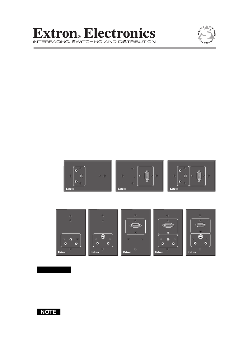
The Extron Wallplates are wall- or furniture-mountable
accessories that provide a convenient way to make pass-through
connections from audio and video source devices.
• WP 120, WP 130, WP 150, WP 170, and WP 180 fit into a
standard U.S. one-gang wall box.
• WP 120 AUS, WP 150 AUS, and WP 170 AUS fit into a
standard Australian wall box.
For step-by-step installation instructions and further details, see
the Wallplates Installation Manual, which is available at
www.extron.com.
68-606-02 Rev. A
02 05
CAUTION
L
VIDEO
R
WP 120 AUS
VIDEO
L
R
WP 120
S-VIDEO
L
R
WP 130
COMPUTER
COMPUTER
AUDIO
WP 150 AUS
COMPUTER
AUDIO
WP 150
L
COMPUTER
AUDIO
VIDEO
R
COMPUTER
AUDIO
VIDEO
L
R
WP 170
AUDIO
S-VIDEO
L
Installation and service must be performed by authorized
personnel only. These units must be installed with accordance
with the National Electrical Code and with local electrical codes.
Use cable clamps to hold the cables in place for strain relief. Trim
back/insulate exposed cable shields with heat shrink to reduce the
chance of short circuits.
These wallplates are passive devices and do not provide buffering or
other processing.
WP 170 AUS
R
WP 180
WP Series Wallplates • Installation
14
Page 2
Installation
Front Panel Features and Cabling
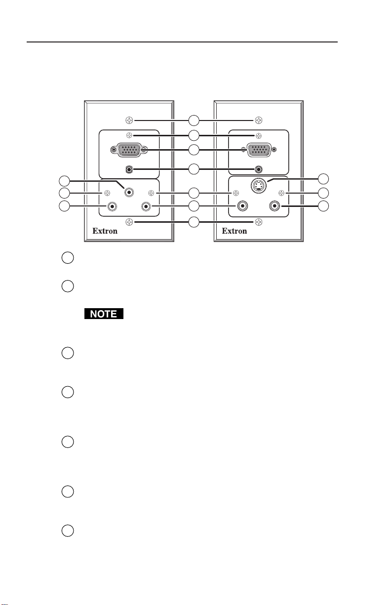
The WP 170 and WP 180 shown below together include all the
front panel connectors that are available in the WP wallplates.
1
COMPUTER
AUDIO
6
2
5
Mounting screws — These fasten the wallplate onto the
1
VIDEO
RL
WP 170
electrical wall box, mud rings, or furniture.
Circuit board attachment screws (all models) — These three
2
small screws fasten the circuit board to the faceplate.
Do not remove these screws while the wallplate is
attached to the wall or furniture or the circuit board may
fall into the wall or furniture.
2
3
4
2
5
1
COMPUTER
S-VIDEO
L
AUDIOAUDIO
7
R
WP 180
2
5
Computer video input (WP 150, WP 150 AUS, WP 170,
3
WP 170 AUS, WP 180) — Attach an RGB computer video source
here. Signals are routed out rear panel female BNC connectors.
Computer Audio input (WP 150, WP 150 AUS, WP 170,
4
WP 170 AUS, WP 180) — Connect computer audio input here.
The signal is routed out the rear panel mini 3.5 mm direct
insertion captive screw connector.
RCA (L and R) audio input (WP 120, WP 120 AUS, WP 130,
5
WP 170, WP 170 AUS, WP 180) — Connect an unbalanced stereo
audio device via these connectors. The signal is routed out the
rear panel RCA direct insertion captive screw connector.
Composite video (Video) input (WP 120, WP 120 AUS, WP 170,
6
WP 170 AUS) — A composite video signal input here is routed
to the rear panel Video BNC connector.
S-video input (WP 130, WP 180) — An S-video signal input here
7
is routed to the rear panel S-video connector.
WP SeriesWallplates • Installation
Page 3

Rear Panel Connectors and Cabling
The WP wallplates share a similar circuit board design: each type of
connector will be in the same place on each model, but the quantity
and selection of connectors differs from model to model. The cabling
and wiring instructions here apply to any wallplate with a particular
connector.
1
2
7
8 8
5
WP 120
Rear
Composite video (Video) output — A female BNC connector.
1
S-video (SVideo) output — A 4-pin mini DIN connector for S-video
2
3
WP 180
Rear
output.
Computer video output:
Blue,
= horizontal sync (H), 7 = vertical sync (V)
6
= Red, 4 = Green, 5 =
3
— Connect coaxial cables to these female BNC
connectors for the appropriate RGB signal format.
RCA audio output — Unbalanced stereo
8
audio from the front panel RCA connectors is
output here. Wire this direct insertion captive
screw connector as shown at right.
The printing on the circuit board may
or may not match the wiring pattern.
Mini 3.5 computer audio output — Unbalanced stereo audio from the
9
LR
front panel mini stereo jack is output here.
Wire this connector as shown at right.
CAUTION
Connect the sleeve to ground
(Gnd). Connecting the sleeve to
a negative (-) terminal may
damage audio circuits in the
TSR
audio device, switcher, or projector.
6
9
4
RED
BLU
RGBHV
Left
L
Ground (Sleeve)
Right
R
RCA
Audio Output
Connector
Tip (Left, +)
T
Sleeve (Ground)
S
Ring (Right, -)
R
Mini 3.5 mm
Audio Output
Connector
HV
GRN
WP Series Wallplates • Installation
32
Page 4

Template
Use the dimensions in the cut-out template below as a guide for
cutting a hole in the wall or furniture. The template is not
100% size. See the full WP Series Installation Manual for a
template for AUS models
WP Series (1-gang) cut-out template
Cut-out area (4.13" H x 2.3" W)
for a regular electrical wall box.
www.extron.com
Cut-out area (3.13" H x
2.13" W) for a compact,
adjustable electrical
wall box
Extron Electronics, USA
1230 South Lewis Street
Anaheim, CA 92805
USA
714.491.1500
Fax 714.491.1517
Cut-out area (2.8"H x 1.9" W)
to install the wallplate without
a wall box
Extron Electronics, Europe
Beeldschermweg 6C
3821 AH Amersfoort
The Netherlands
+31.33.453.4040
Fax +31.33.453.4050
© 2005 Extron Electronics. All rights reserved.
Extron Electronics, Asia
135 Joo Seng Road, #04-01
PM Industrial Building
Singapore 368363
+65.6383.4400
Fax +65.6383.4664
Extron Electronics, Japan
Kyodo Building
16 Ichibancho
Chiyoda-ku, Tokyo 102-0082 Japan
+81.3.3511.7655
Fax +81.3.3511.7656
 Loading...