

Page 1
x
Se
lf-
M
eta
(
(4) 1/
Ass
e
ve
(
l
M
ou
lat
e
K
WMK 160 • Installation Guide
IMPORTANT SAFETY INSTRUCTIONS
Read all instructions before using this furnishing.
When using this furnishing, basic precautions should always be followed, including the following:
DANGER: Risk of Electric Shock. Disconnect power to this furnishing before cleaning.
WARNING: Risk of Electric Shock. Devices used in this furnishing should be connected to a properly grounded outlet only.
See Grounding Instructions in the device manual.
WARNING: Risk of Personal Injury. Read and follow the steps below to reduce the risk of burns, fire, electric shock, or injury
to persons.
1. Always unplug devices installed in this furnishing from outlets before putting on or taking off parts.
2. Close supervision is necessary when this furnishing is used by, or near children, invalid, or disabled persons.
3. Use this furnishing only for its intended use as described in these instructions. Do not use attachments not recommended by
the manufacturer.
4. Never operate a device in this furnishing if it is not working properly, if it has been dropped or damaged, or dropped into
water. Return the device used in this furnishing to a service center for examination and repair.
5. Never operate the furnishing with the air openings blocked. Keep the air openings free of lint, hair, and the like.
6. Never drop or insert any object into any opening.
7. Do not use outdoors.
8. Do not operate where aerosol (spray) products are being used or where oxygen is being administered.
9. To disconnect the devices, turn all controls to the off position, then remove plugs from outlet.
SAVE THESE INSTRUCTIONS
GROUNDING INSTRUCTIONS
This product must be connected to a grounded metal, permanent wiring system, or an equipment-grounding conductor must
be run with the circuit conductors and connected to the equipment-grounding terminal or lead on the product.
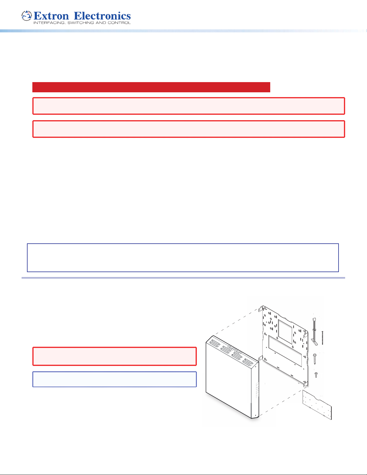
The Extron® WMK 160 Wall Mount Kit is used for hanging WallVault®
System AV products on a wall near a at screen display or short throw projector.
The WMK 160 has a 17.3 x 16.5 x 2.75 inches (43.9 x 41.9 x 6.9
cm) enclosure, and a base plate on which to mount the switcher (for
example the PVS 405D) and the associated power supply, with room
for cable management.
In addition, an accessory device can be mounted on the base plate.
The cover has knockouts on three sides that allow external raceways
to be used where needed for cabling.
WARNING: Risk of Personal Injury. Maximum load for the
WMK 160 is 15 lbs (7 kg)
NOTE: The WMK 160 is to be used only with Extron UL listed
products.
The key components (base plate, cover, and PVS switcher mounting
plate) of the WMK 160 are shown in gure 1. Included in the kit are the
following:
(4) ¼-20 x 2" pan head bolts, (4) ¼" KapToggle® assemblies,
(2) #14 x 1¾" self tapping metal/wood screws,
(4) cover screws.
Not shown but included are (3) 4-40 x ¼" screws, (2) tie wraps (15"),
(8) 4-40 x 3/16" screws (used to attach other Extron devices).
160 Base P
1) WM
(1) WMK 160 Base Plate
(1) WMK 160 Cover
Figure 1. WMK 160 parts
4"
(4) 1/4" KapToggle
Assemblies
4)
(4) 1/4-20 x 2"
Pan Head Bolts
(2) #14 x 1 3/4"
(2) #14
Self-tapping
Metal/Wood Screws
(4) Cover Screws
(4) Co
(1) PoleVault Switcher
1) Po
Mounting Plate
®
1
Page 2
WMK 160 • Installation Guide (Continued)
Mounting
WMK 160
Base Plate
Installation
NOTE: Refer to local building standards and codes to verify that the installation will meet the regulatory requirements.
Observe all local and national building and safety codes, UL requirements, and ADA accessibility guidelines.
Before installation identify the type of wall (masonry or non-masonry) and the location where the WMK 160 will be installed.
This determines the installation approach and type of fasteners needed to secure the plate to the wall.
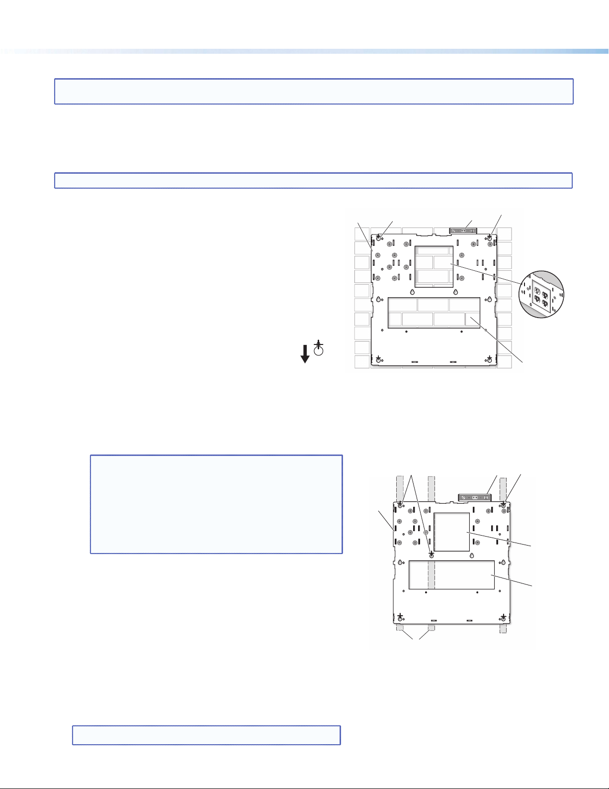
Step 1. — Mount the Base Plate
Follow the steps within 1A or 1B, as applicable.
NOTE: The base plate can be installed over an existing electrical outlet (see figure 2).
1A. To mount the WMK 160 onto masonry walls:
i. Hold the base against the wall, level it, and mark the
positions of four slotted mounting holes (indicated by
+ marks in gure2). Set the plate aside.
ii. Using a masonry drill bit, drill 1¾ inch (4.4 cm) deep
pilot holes at the marked locations.
iii. Screw in ¼ x 1¾ inch masonry screws (not supplied)
until a gap of about 3/8 inch (9 mm) remains between
the wall and the screw heads.
iv. Align the slotted mounting holes of the base plate
over the installed screws, then slide the plate
down so the screws t into the slots.
v. Verify level and position and tighten all the screws to secure
the plate ush to the wall.
Proceed to step 2.
1B. To mount the WMK 160 onto a non-masonry wall:
i. At the desired site, locate and mark the wall studs.
NOTES:
• For ideal installation secure the base plate to at least
one wall stud (see figure 3). Drywall KapToggles can be
used for holes not aligned with studs.
• Always use the widest spacing of screws and
KapToggles.
• The base plate can be installed over an existing
electrical outlet (see figure 2).
ii. Hold and level the base plate against the wall and mark
the positions of the slotted mounting holes that are on
the stud lines (see gure 3, indicated by + marks). Where
applicable, mark the mounting holes on the wall for
drywall toggles.
iii. If the cables are to be run behind the wall to the
WMK 160 location, mark the cutout area on the wall for
the signal cable access hole (see gure 3). Remove the base
plate and set the plate aside.
iv. Drill 1¾ inch (4.4 cm) deep pilot holes at the hole marks.
v. Cut out the marked area for cable access.
vi. At the pilot holes, screw in the screws until a gap of about
3/8 inch (9 mm) remains between the wall and the screw heads.
WMK 160
Base Plate
Mounting
Holes
Figure 2. Masonry wall mounting
Holes
Wall Studs
Figure 3. Non-masonry wall mounting
Level
Marker for
Pilot Hole
Level
Cutout for
Electical
Outlet
Cutout for
Signal Cable
Access
Marker for
Pilot Hole
Cutout for
Electrical
Outlet
Cutout for
Signal Cable
Access
NOTE: If using toggle assemblies, see gure 4 for method.
2
Page 3

vii. Align the slotted mounting holes in the base plate
a. Grasp handle, collapse
toggle and inser
b. Slide plastic washer
over the installed screws, then slide the plate down so
the screw t into the slots.
viii. Verify level and position, and tighten down all the
screws to secure the plate ush to the wall.
Step 2. — Mount the Switcher, Power Supply, and Accessory Device
NOTE: Always use a power supply supplied or specified by Extron. Use of an unauthorized power supply voids all
regulatory compliance certification and may cause damage to the supply and the end product. Unless otherwise stated,
the AC/DC adapters are not suitable for use in air handling spaces or in wall cavities. The installation must always be
in accordance with the applicable provisions of National Electrical Code ANSI/NFPA 70, article 75 and the Canadian
Electrical Code part 1, section 16. The power supply shall not be permanently fixed to a building structure or similar
structure.
a. Invert the switcher and place it (base up) on a at surface.
Place the mounting plate at on the switcher base with the plate
tabs (raised section up) over the edge of the front panel. Align the
two mounting holes in the switcher base with the corresponding
holes on the mounting plate. Secure the plate to the switcher with
the supplied 4-40 x ¼ inch screws.
b. Secure the switcher mounting plate (with switcher
attached) to the base plate by sliding the two tabs into
the slots at the bottom edge of the base plate. Secure to
the standoffs with 4-40 x 3/16 inch screws (see gure 5).
c. Secure the power supply to the right of the electrical outlet cutout
by threading the supplied tie wraps through the loops on the
base plate. Attach it so the cables are easily and safely routed
to the electrical outlet and switcher alike.
d. An optional ¼ rack, 3 inch deep accessory device, such as the
Extron IPL TS2, can be installed on the WMK 160 base plate.
To do so, place the device towards the top of the base plate,
align the holes on the base plate and the device, and secure with
the supplied 4-40 x 3/16 inch screws.
t into wall.
c. Cut off handle close to wall.
down into pilot hole.
d. Hand screw in pan head
bolt until 1/8" gap remains.
Figure 4. Toggle assembly installation
(2) 4-40 x 3/16" screws
LAN 1 LAN 2 LAN 3
G
TxRx
R
G
RS-232
S
REMOTE
Ω
L
4/8
IR
OUTPUTS
SPEAKER
OVER PVT
OR SHORT
GROUND
DO NOT
AMPLIFIED AUDIO OUT
VOICELIFT
AUX
+V
R
PVS 405SA IP
L
SENSOR
INPUT 5
PAGING
R
L
PVT IN
HDMI
AUDIO OUT
LINK
OUTPUT
PVT IN
3/4
1/2
SIG LINK SIG
INPUTS
3A MAX
12V
POWER
(2) 4-40 x 1/4" screws
Figure 5. Attach the switcher to the mounting
plate and secure both to the base plate.
Step 3. — Run Cables
Run signal cables from the proposed PVT input wallplates, control
device location, and the speakers to the WMK 160 location. Cables can
be routed behind the walls, or through a surface raceway (for example,
Wiremold® V700 or 2400 series) directly to the WMK 160.
3A. If running cable behind the walls:
3B. If using a surface raceway:
i. Run all the cables from the various locations to the WMK and through
the access cutout.
i. Slide the WMK cover over the base plate, then identify and
mark the most suitable raceway entrance to the WMK 160.
ii. Run the raceway from the signal source, speaker, and display
locations to the marked raceway entrance at the WMK.
iii. Remove the WMK cover, and remove the desired knockout.
iv. Attach the raceway to the wall. Run cables from the sources
and outputs through the raceway to the WMK.
V700
2400
Raceway Option
Signal Cable
Access Cutout
Figure 6. Cabling run options
Electrical Access
Cutout
3
Page 4

WMK 160 • Installation Guide (Continued)
Line Out
Step 4. — Cable the Switcher
a. Connect the cables from the PVT wallplates, control device (MediaLink Controller), speakers, and optional accessories
(VoiceLift® and Page Sensor Kit) to the rear ports of the switcher (see gure 7 below).
Refer to the PVS 405D Setup Guide for additional details.
NOTE: If using a device other than a PVS 405D (such as a PVS 305SA IP), refer to the user guide for that device.
b. Run an HDMI cable from the switcher to the output display device through the wall or, where tted, the raceway.
c. Connect the power supply to the switcher and plug it in to the electrical outlet.
NOTE: If the electrical outlet is outside the WMK, pass the IEC power cable out through one of the raceway
knockouts.
Power Connector
Supplied PVS Switcher
External Power Supply
(12 VDC, 4 A max.)
POWER
12V
3A MAX
Output (Audio)
INPUTS OUTPUT AUDIO OUT
1/2
3/4
AUDIO
IN OUT
VGA IN
LOCAL OUT
HDMI
HDMI
Connector
HDMI Output
to Display Device
SIG LINKSIG LINK
PVT IN PVT IN
HDMI/RGB
AUDIO IN
HDMI IN
IR OUT
S
G
PVT SW HDMI RGB D
HDMI or RGB video/audio, Inputs1/2 and 3/4
1 CAT 5e cable with RJ-45 connectors
L
R
INPUT 5
L
R
Aux Audio
Input 5
Audio Output to Speakers
Paging
Sensor
+V
PVS 405SA IP
PAGING
SENSOR
VOICELIFT
+V
AUX OVER PVT REMOTE
Aux
VoiceLift
Input
Receiver
PVS terminal
Speaker
(left and right)
wire color
Red Positive (+)
Black Negative (-)
AMPLIFIED AUDIO OUT
DO NOT
GROUND
OR SHORT
SPEAKER
OUTPUTS
IR
SG G
SG
IR control
Tx Rx
Figure 7. Cabling the switcher (PVS 405D shown)
LR
4/8
Ω
RS-232
MLC 104 IP Plus
RS-232 input
NOTE: You must connect
a ground wire between
the MLC and PVS.
Ground (Gnd)
Receive (Rx)
Transmit (Tx)
Transmit (Tx)
Receive (Rx)
B
A
NOTE: If you use cable that has
a drain wire, tie the drain wire
to ground at both ends.
3-port 10/100 Ethernet Switch
Connect to ports as follows:
1. TCP/IP network
2. MLC controller
3. Optional network device
LAN 1 LAN 2 LAN 3
MLC
wire color
White Tx on RS-232 port
Violet Rx on RS-232 port
Drain wire Ground (G)
Black Po wer Supply (–)
Red Power Supply (+)
B
A
Tx
Rx
AB
GROUND
GROUND
MLS PWR
RS-232 12V
To PVS terminal
B
Ground
+12 VDC input
MLC 104 IP Plus right side
+12V IN
panel MLS and Power ports
To Supplied
PVS Switcher
Power Supply
(12 VDC, 4 A max.)
4
Page 5

Step 5. — Final Installation.
a. After completing cabling, place the cover over the installed plate,
and secure at each corner with the provided cover screws.
NOTE: Ensure any cables exiting the box to a display
device and external electrical outlet pass through a
raceway knockout.
b. Switch on the display device, control device, signal sources,
and then adjust and congure the system as needed.
For full conguration and setup details, refer to the PoleVault System
Installation Guide (featuring the PVS 405D Switcher), the MLC 104
Plus Series Reference Guide, and the PVS 405D User Guide, all
available online at www.extron.com.
LAN 1 LAN 2 LAN 3
TxRx
G G
RS-232
S
REMOTE
Ω
L R
4/8
IR
OUTPUTS
SPEAKER
OVER PVT
OR SHORT
GROUND
DO NOT
AMPLIFIED AUDIO OUT
VOICELIFT
AUX
+V
R
PVS 405SA IP
L
INPUT 5
SENSOR
PAGING
R
L
PVT IN
HDMI
AUDIO OUT
LINK
OUTPUT
PVT IN
3/4
1/2
SIG LINK SIG
INPUTS
3A MAX
12V
POWER
Figure 8. Attach WMK 160 cover
5
Page 6

WMK 160 • Installation Guide (Continued)
1.50"
Bottom View
WMK 160 Dimensions
Side View
(5.08 cm)
Both Sides
2.75"
(6.99 cm)
16.37"
(32.69 cm)
Base Front View
Top View
Both Sides
17.07"
(39.04 cm)
15.50"
(39.04 cm)
Extron Headquarters
+1.800.633.9876 (Inside USA/Canada Only)
Extron Europe
+31.33.453.4040
© 2013 Extron Electronics — All rights reserved. All trademarks mentioned are the property of their respective owners. www.extron.com
6
Both
Sides
Extron Asia
+65.6383.4400
Extron Japan
+81.3.3511.7655
16.51"
(33.02 cm)
Cover Front View
Extron China
+86.21.3760.1568
Extron Middle East
+971.4.299.1800
17.27"
(39.37 cm)
Extron Korea
+82.2.3444.1571
Extron India
+91.80.3055.3777
68-2384-01
Rev. A
08 13
 Loading...