

Page 1
User’s Manual
www.extron.com
Extron Electronics, USA
1230 South Lewis Street
Anaheim, CA 92805
USA
714.491.1500
Fax 714.491.1517
© 2006 Extron Electronics. All rights reserved.
Extron Electronics, Europe
Beeldschermweg 6C
3821 AH Amersfoort
The Netherlands
+31.33.453.4040
Fax +31.33.453.4050
Extron Electronics, Asia
135 Joo Seng Road, #04-01
PM Industrial Building
Singapore 368363
+65.6383.4400
Fax +65.6383.4664
Extron Electronics, Japan
Kyodo Building
16 Ichibancho
Chiyoda-ku, Tokyo 102-0082 Japan
+81.3.3511.7655
Fax +81.3.3511.7656
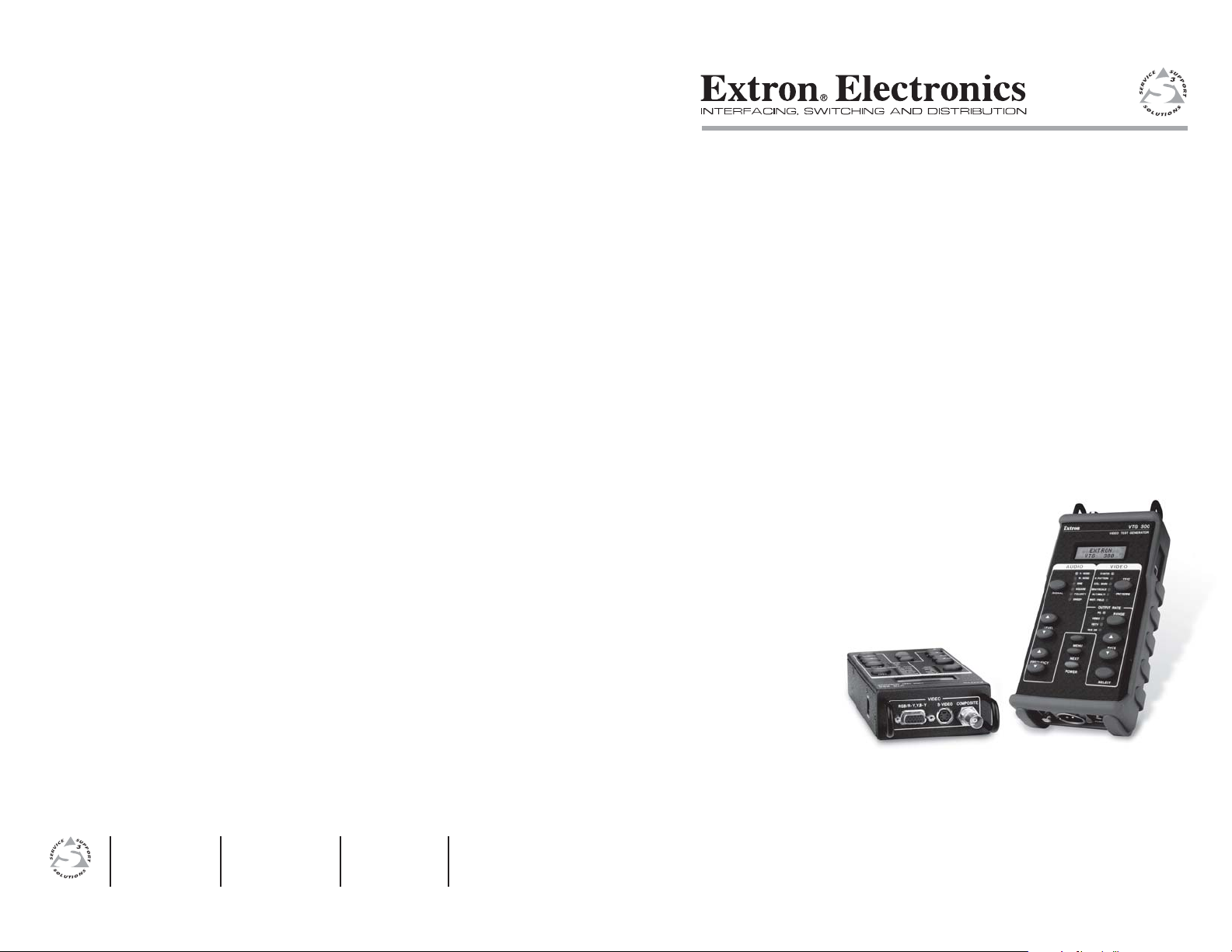
VTG 300/300R
Video Test Generator with Audio
68-737-01 Rev. D
06 06
Page 2

Precautions
Safety Instructions • English
This symbol is intended to alert the user of
important operating and maintenance (servicing)
instructions in the literature provided with the
equipment.
This symbol is intended to alert the user of the
presence of uninsulated dangerous voltage within
the product's enclosure that may present a risk of
electric shock.
Caution
Read Instructions • Read and understand all safety and operating
instructions before using the equipment.
Retain Instructions • The safety instructions should be kept for future
reference.
Follow Warnings • Follow all warnings and instructions marked on the
equipment or in the user information.
Consignes de Sécurité • Français
Ce symbole sert à avertir l’utilisateur que la
documentation fournie avec le matériel contient des
instructions importantes concernant l’exploitation
et la maintenance (réparation).
Ce symbole sert à avertir l’utilisateur de la présence
dans le boîtier de l’appareil de tensions
dangereuses non isolées posant des risques
d’électrocution.
Attention
Lire les instructions• Prendre connaissance de toutes les consignes de
sécurité et d’exploitation avant d’utiliser le matériel.
Conserver les instructions• Ranger les consignes de sécurité afin de
pouvoir les consulter à l’avenir.
Respecter les avertissements • Observer tous les avertissements et
consignes marqués sur le matériel ou présentés dans la documentation
utilisateur.
Sicherheitsanleitungen • Deutsch
Dieses Symbol soll dem Benutzer in der im
Lieferumfang enthaltenen Dokumentation
besonders wichtige Hinweise zur Bedienung und
Wartung (Instandhaltung) geben.
Dieses Symbol soll den Benutzer darauf
aufmerksam machen, daß im Inneren des
Gehäuses dieses Produktes gefährliche
Spannungen, die nicht isoliert sind und die einen
elektrischen Schock verursachen können,
herrschen.
Achtung
Lesen der Anleitungen • Bevor Sie das Gerät zum ersten Mal verwenden,
sollten Sie alle Sicherheits-und Bedienungsanleitungen genau
durchlesen und verstehen.
Aufbewahren der Anleitungen • Die Hinweise zur elektrischen Sicherheit
des Produktes sollten Sie aufbewahren, damit Sie im Bedarfsfall darauf
zurückgreifen können.
Befolgen der Warnhinweise • Befolgen Sie alle Warnhinweise und
Anleitungen auf dem Gerät oder in der Benutzerdokumentation.
Instrucciones de seguridad • Español
Este símbolo se utiliza para advertir al usuario
sobre instrucciones importantes de operación y
mantenimiento (o cambio de partes) que se desean
destacar en el contenido de la documentación
suministrada con los equipos.
Este símbolo se utiliza para advertir al usuario
sobre la presencia de elementos con voltaje
peligroso sin protección aislante, que puedan
encontrarse dentro de la caja o alojamiento del
producto, y que puedan representar riesgo de
electrocución.
Precaucion
Leer las instrucciones • Leer y analizar todas las instrucciones de
operación y seguridad, antes de usar el equipo.
Conservar las instrucciones • Conservar las instrucciones de seguridad
para futura consulta.
Obedecer las advertencias • Todas las advertencias e instrucciones
marcadas en el equipo o en la documentación del usuario, deben ser
obedecidas.
Avoid Attachments • Do not use tools or attachments that are not recommended by the
equipment manufacturer because they may be hazardous.
Warning
Power sources • This equipment should be operated only from the power source
indicated on the product. This equipment is intended to be used with a main
power system with a grounded (neutral) conductor. The third (grounding) pin is
a safety feature, do not attempt to bypass or disable it.
Power disconnection • To remove power from the equipment safely, remove all
power cords from the rear of the equipment, or the desktop power module (if
detachable), or from the power source receptacle (wall plug).
Power cord protection • Power cords should be routed so that they are not likely to
be stepped on or pinched by items placed upon or against them.
Servicing • Refer all servicing to qualified service personnel. There are no user-
serviceable parts inside. To prevent the risk of shock, do not attempt to service
this equipment yourself because opening or removing covers may expose you to
dangerous voltage or other hazards.
Slots and openings • If the equipment has slots or holes in the enclosure, these are
provided to prevent overheating of sensitive components inside. These openings
must never be blocked by other objects.
Lithium battery • There is a danger of explosion if battery is incorrectly replaced.
Replace it only with the same or equivalent type recommended by the
manufacturer. Dispose of used batteries according to the manufacturer's
instructions.
Eviter les pièces de fixation • Ne pas utiliser de pièces de fixation ni d’outils non
recommandés par le fabricant du matériel car cela risquerait de poser certains dangers.
Avertissement
Alimentations• Ne faire fonctionner ce matériel qu’avec la source d’alimentation indiquée
sur l’appareil. Ce matériel doit être utilisé avec une alimentation principale comportant
un fil de terre (neutre). Le troisième contact (de mise à la terre) constitue un dispositif de
sécurité : n’essayez pas de la contourner ni de la désactiver.
Déconnexion de l’alimentation• Pour mettre le matériel hors tension sans danger,
déconnectez tous les cordons d’alimentation de l’arrière de l’appareil ou du
module d’alimentation de bureau (s’il est amovible) ou encore de la prise secteur.
Protection du cordon d’alimentation • Acheminer les cordons d’alimentation de
manière à ce que personne ne risque de marcher dessus et à ce qu’ils ne soient
pas écrasés ou pincés par des objets.
Réparation-maintenance • Faire exécuter toutes les interventions de réparation-
maintenance par un technicien qualifié. Aucun des éléments internes ne peut être
réparé par l’utilisateur. Afin d’éviter tout danger d’électrocution, l’utilisateur ne
doit pas essayer de procéder lui-même à ces opérations car l’ouverture ou le
retrait des couvercles risquent de l’exposer à de hautes tensions et autres dangers.
Fentes et orifices • Si le boîtier de l’appareil comporte des fentes ou des orifices,
ceux-ci servent à empêcher les composants internes sensibles de surchauffer. Ces
ouvertures ne doivent jamais être bloquées par des objets.
Lithium Batterie • Il a danger d'explosion s'll y a remplacment incorrect de la
batterie. Remplacer uniquement avec une batterie du meme type ou d'un ype
equivalent recommande par le constructeur. Mettre au reut les batteries usagees
conformement aux instructions du fabricant.
Keine Zusatzgeräte • Verwenden Sie keine Werkzeuge oder Zusatzgeräte, die nicht
ausdrücklich vom Hersteller empfohlen wurden, da diese eine Gefahrenquelle darstellen
können.
Vorsicht
Stromquellen • Dieses Gerät sollte nur über die auf dem Produkt angegebene
Stromquelle betrieben werden. Dieses Gerät wurde für eine Verwendung mit
einer Hauptstromleitung mit einem geerdeten (neutralen) Leiter konzipiert. Der
dritte Kontakt ist für einen Erdanschluß, und stellt eine Sicherheitsfunktion dar.
Diese sollte nicht umgangen oder außer Betrieb gesetzt werden.
Stromunterbrechung • Um das Gerät auf sichere Weise vom Netz zu trennen,
sollten Sie alle Netzkabel aus der Rückseite des Gerätes, aus der externen
Stomversorgung (falls dies möglich ist) oder aus der Wandsteckdose ziehen.
Schutz des Netzkabels • Netzkabel sollten stets so verlegt werden, daß sie nicht
im Weg liegen und niemand darauf treten kann oder Objekte darauf- oder
unmittelbar dagegengestellt werden können.
Wartung • Alle Wartungsmaßnahmen sollten nur von qualifiziertem
Servicepersonal durchgeführt werden. Die internen Komponenten des Gerätes
sind wartungsfrei. Zur Vermeidung eines elektrischen Schocks versuchen Sie in
keinem Fall, dieses Gerät selbst öffnen, da beim Entfernen der Abdeckungen die
Gefahr eines elektrischen Schlags und/oder andere Gefahren bestehen.
Schlitze und Öffnungen • Wenn das Gerät Schlitze oder Löcher im Gehäuse
aufweist, dienen diese zur Vermeidung einer Überhitzung der empfindlichen
Teile im Inneren. Diese Öffnungen dürfen niemals von anderen Objekten
blockiert werden.
Litium-Batterie • Explosionsgefahr, falls die Batterie nicht richtig ersetzt wird.
Ersetzen Sie verbrauchte Batterien nur durch den gleichen oder einen
vergleichbaren Batterietyp, der auch vom Hersteller empfohlen wird. Entsorgen
Sie verbrauchte Batterien bitte gemäß den Herstelleranweisungen.
Evitar el uso de accesorios • No usar herramientas o accesorios que no sean
especificamente recomendados por el fabricante, ya que podrian implicar riesgos.
Advertencia
Alimentación eléctrica • Este equipo debe conectarse únicamente a la fuente/tipo de
alimentación eléctrica indicada en el mismo. La alimentación eléctrica de este equipo debe
provenir de un sistema de distribución general con conductor neutro a tierra. La tercera
pata (puesta a tierra) es una medida de seguridad, no puentearia ni eliminaria.
Desconexión de alimentación eléctrica • Para desconectar con seguridad la acometida
de alimentación eléctrica al equipo, desenchufar todos los cables de alimentación en el
panel trasero del equipo, o desenchufar el módulo de alimentación (si fuera
independiente), o desenchufar el cable del receptáculo de la pared.
Protección del cables de alimentación • Los cables de alimentación eléctrica se deben
instalar en lugares donde no sean pisados ni apretados por objetos que se puedan
apoyar sobre ellos.
Reparaciones/mantenimiento • Solicitar siempre los servicios técnicos de personal
calificado. En el interior no hay partes a las que el usuario deba acceder. Para
evitar riesgo de electrocución, no intentar personalmente la reparación/
mantenimiento de este equipo, ya que al abrir o extraer las tapas puede quedar
expuesto a voltajes peligrosos u otros riesgos.
Ranuras y aberturas • Si el equipo posee ranuras o orificios en su caja/alojamiento,
es para evitar el sobrecalientamiento de componentes internos sensibles. Estas
aberturas nunca se deben obstruir con otros objetos.
Batería de litio • Existe riesgo de explosión si esta batería se coloca en la posición
incorrecta. Cambiar esta batería únicamente con el mismo tipo (o su equivalente)
recomendado por el fabricante. Desachar las baterías usadas siguiendo las
instrucciones del fabricante.
FCC Class A Notice
Note: This equipment has been tested and found to comply with the limits for a
Class A digital device, pursuant to part 15 of the FCC Rules. These limits are designed
to provide reasonable protection against harmful interference when the equipment is
operated in a commercial environment. This equipment generates, uses and can
radiate radio frequency energy and, if not installed and used in accordance with the
instruction manual, may cause harmful interference to radio communications.
Operation of this equipment in a residential area is likely to cause harmful
interference, in which case the user will be required to correct the interference at his
own expense.
Note: This unit was tested with shielded cables on the peripheral devices. Shielded
cables must be used with the unit to ensure compliance.
Extron’s Warranty
Extron Electronics warrants this product against defects in materials and
workmanship for a period of three years from the date of purchase. In the event of
malfunction during the warranty period attributable directly to faulty workmanship
and/or materials, Extron Electronics will, at its option, repair or replace said products
or components, to whatever extent it shall deem necessary to restore said product to
proper operating condition, provided that it is returned within the warranty period,
with proof of purchase and description of malfunction to:
USA, Canada, South America, Europe, Africa, and the Middle East:
and Central America:
Extron Electronics Beeldschermweg 6C
1001 East Ball Road 3821 AH Amersfoort
Anaheim, CA 92805, USA The Netherlands
Asia: Japan:
Extron Electronics, Asia Kyodo Building
135 Joo Seng Road, #04-01 16 Ichibancho
PM Industrial Bldg. Chiyoda-ku, Tokyo 102-0082
Singapore 368363 Japan
This Limited Warranty does not apply if the fault has been caused by misuse,
improper handling care, electrical or mechanical abuse, abnormal operating conditions
or non-Extron authorized modification to the product.
If it has been determined that the product is defective, please call Extron and ask for
an Applications Engineer at (714) 491-1500 (USA), 31.33.453.4040 (Europe),
65.6383.4400 (Asia), or 81.3.3511.7655 (Japan) to receive an RA# (Return
Authorization number). This will begin the repair process as quickly as possible.
Units must be returned insured, with shipping charges prepaid. If not insured,
you assume the risk of loss or damage during shipment. Returned units must
include the serial number and a description of the problem, as well as the name of
the person to contact in case there are any questions.
Extron Electronics makes no further warranties either expressed or implied with
respect to the product and its quality, performance, merchantability, or fitness for any
particular use. In no event will Extron Electronics be liable for direct, indirect, or
consequential damages resulting from any defect in this product even if Extron
Electronics has been advised of such damage.
Please note that laws vary from state to state and country to country, and that some
provisions of this warranty may not apply to you.
Extron Electronics, Europe
Extron Electronics, Japan
Page 3

ᅝܼ乏ⶹ•Ё᭛
䖭Ͼヺোᦤ⼎⫼᠋䆹䆒⫼᠋ݠЁ
᳝䞡㽕ⱘ᪡㓈ᡸ䇈ᯢDŽ
䖭Ͼヺো䄺⫼᠋䆹䆒ᴎݙ᳝
䴆ⱘ䰽⬉ˈ᳝㾺⬉䰽DŽ
⊼ᛣ
䯙䇏䇈ᯢк• 䑩ㅸỀ䑩嬦嫿 ⡈⼆枼敆嬼䍇 夤ㆁ㙊
⫊₩⏍Ề䑩嬵㕏ɿ
ֱᄬ䇈ᯢк• 䑩ㅸⷕ⪙⫊₩嬵㕏ᶧḦ⡈⭇㚦 Ề䑩ɿ
䙉ᅜ䄺• 䑩ㅸⷕ徶⫉␂⏍䑩ㅸ㉈⊘ᵋ䗅ㆁ㙊⫊₩
⏍㐎ẝ嬵㕏ɿ
䙓ܡ䗑ࡴ• ᵎ壂Ề䑩嬦␂⋃⒇㯢㙊㋩劑䗅₸ㅗ弾
⇡嫿⡈澤Ḧ忀₎⊲斪ɿ
䄺
⬉⑤• 嬦嫿⡈⌫倾Ề䑩␂ ᵋ㝈㕏䗅䑶㷑ɿ嫿⡈⼆枼
Ề䑩㙊♱一䗅Ờ䑶䰼丠Ờ䑶ɿ䩭ᵊ 㚢一澠♱一澡㕰
⫊₩嫿㓾澤ᵎ倾ᵎ䑩ㅗ崴弈ɿ
ᢨᥝ⬉⑤• ᵻ⫊₩♱ḏ嫿⡈㈕㋊䑶㷑澤嬸㈕㋊ㆁ㙊嫿
⡈⍏ㅗ㞍暣䑶㷑䗅䑶㷑一澤ㅗḼẖ㋦ⅱⵃ䑶䰼丠䗅
䑶㷑一ɿ
⬉⑤㒓ֱᡸ• ⣦Ⓟⵄ一澤忀₎埬嵪嵐澤ㅗ愎䆪㉥⋌ɿ
㓈ᡸ•ㆁ㙊丵Ἧ⼆枼䑲嫥嬂䗅丵Ἧ⎙弜垍ɿ嫿⡈
怩㯢㙊䑩ㅸ⌰Ḧ㘵㊣䗅昷ḷɿᵻ忀₎℻䋱大䑶⊲斪
ᵎ壂儫ⴲ嬖☿㆔⹁嫿⡈䘗⪑丵Ἧ嬦嫿⡈ɿ
䗮亢ᄨ• 㙊嫿⡈㙻⠴ᵋ㙊彛栏㤾ㅗ⪕澤⫄ḭ㕰䑩 㚦
敳㪣㙻㒐だ₄ḷ弈䀮ɿᵎ壂䑩Ḽẖ ᵝ壀㉢Ẑ彛
栏⪕ɿ
䫖⬉∴ • ᵎ㪤䞯䗅㘵㊣䑶㮡ṛ㙊䅇㿹䗅⊲斪ɿ⼆枼Ề䑩
ᵏ⋃⫷㋩劑 䗅䘹⍍ㅗ 䘹弒 ⛌⌸䗅䑶㮡ɿ㉊䂨䑠 ⋃
䗅⸻嫯⡅ 䍇ⷠ⹄䑶㮡ɿ
Page 4
Quick Start Guide — VTG 300/300R
RGB/Y,R-Y,R-Y S-VIDEO COMPOSITE
VIDEO
Top panel
AUDIO
3
2
1
Bottom panel
CAUTION
Operation and service must be performed by authorized
personnel only. These units must be operated in
accordance with national and local electrical codes.
Prior to using the VTG 300R for the first time, please be
sure that the batteries are fully charged.
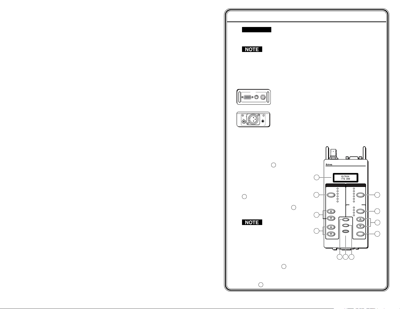
To operate the VTG 300/300R, follow these steps and see chapter 2.
Step 1
Connect a video device to one of the top panel connectors or
connect an audio device to one of the bottom panel connectors.
The video connectors located on the top panel will
accommodate RGB, component, S-video, and
composite video output.
The audio connectors located on the bottom panel
will accommodate unbalanced mono audio on the
RCA jack, balanced mono audio on the 3-pin XLR
connector, and unbalanced mono audio (both left
and right channels) on the 3.5 mm mini jack.
Step 2
Power up the VTG 300/300R.
Using either the external
power supply or internal
batteries, hold down the
Power button 7 for one
second.
Step 3
1
If generating an audio signal,
press the audio Signal button
2
to select an audio signal, as
2
indicated by the lit LED. Press
the audio Level buttons 3 to
adjust the RMS signal level.
3
See the Audio
Setup menu
section in chapter 2
4
to specify either dBu
or dBV as the signal
level unit.
When the signal type is either a
sine or square wave, press the
Frequency buttons 4 to adjust the frequency from 20 Hz to 20 kHz
(sine) or 20 Hz to 5 kHz (square).
When the signal type is frequency sweep, press the Frequency
buttons
4
to adjust the sweep interval from 1.5 sec to 150 sec.
VTG 300/300R • Quick Start Guide
Front panel
AUDIO VIDEO
P.NO IS E
W. NOISE
SINE
SQUARE
SIGNAL
POLARITY
SWEEP
LEVEL
FREQUENCY
5
VIDEO TEST GENERATOR
X-HATCH
H PATTERN
COL. BARS
GRAYSCALE
ALT/ MULTI
WHT. FIELD
OUTPUT RATE
PC
VIDEO
HDTV
16:9 HR
MENU
NEXT
POWER
7
6
VTG 300
TEST
PATTERNS
RANGE
RATE
SELECT
8
9
10
11
QS-1
Page 5
Quick Start Guide — VTG 300/300R, cont’d
Table of Contents
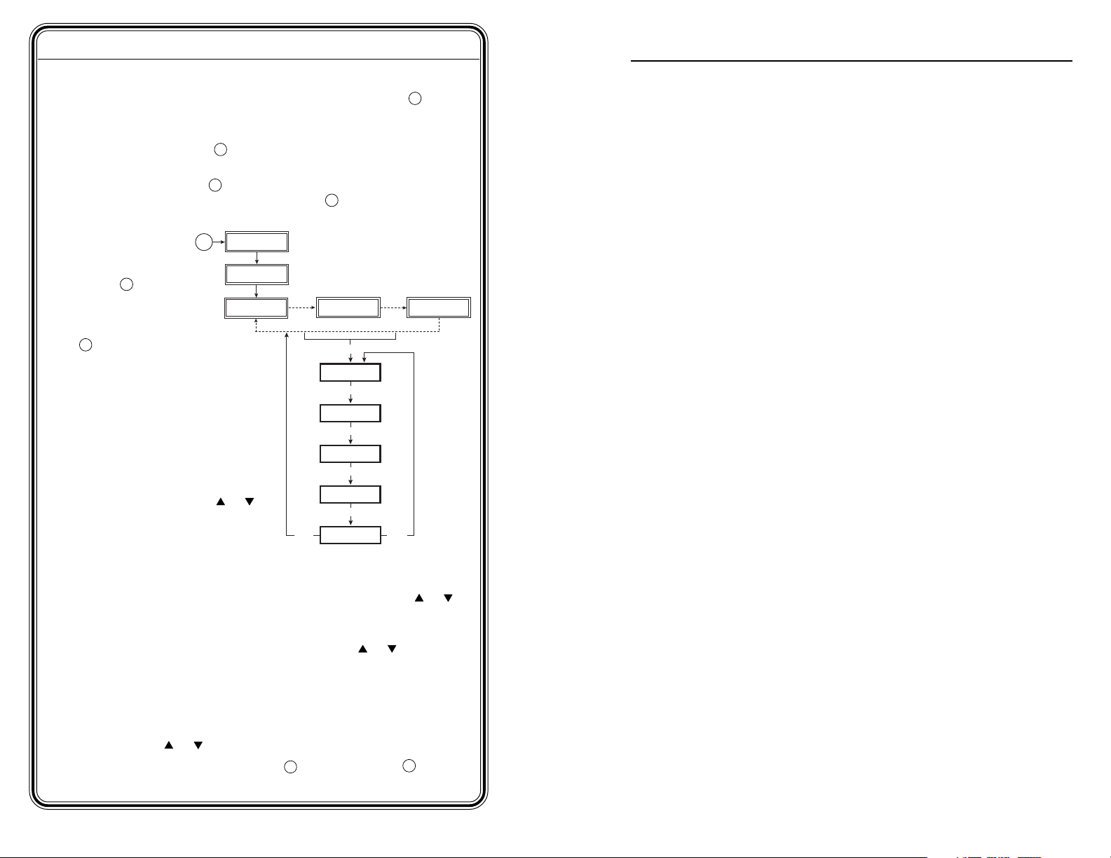
Step 4
If generating a video signal, press the Test Patterns button 8 to
select a test pattern type, as indicated by the lit LED. See Selecting a
Video Test Pattern in chapter 2.
9
Press the Range button
range types, as indicated by the lit LED.
Press the Rate buttons
selected range, then press the Select button 11 to activate the
selection.
Menu System
Use the Menu
button 5 to
advance through
the main menus.
Use the Next button
6
to navigate through the
submenu system. See the
Menus, Configuration, and
Adjustments section in chapter 2.
Grayscale or white field: To
select a grayscale or white field
test pattern, select the Test
Pattern Setup main menu, then
go to the the Grayscale
submenu or the White Field
submenu and press any
button to make a selection. The
grayscale choices are 32-level
split and ramp. The white field
choices are full field, 80% window, and 20% window.
To select the audio level unit dBV or dBu: Select the Audio units
submenu from the Audio setup main menu, then press any
button to make a selection.
To select RGB or Y, B-Y, R-Y: Select the HD15 Video format submenu
from the Video Setup main menu, then press any
make a selection.
Enable@Power Up feature: Select which outputs (audio or video) are
enabled when the VTG is turned on. This feature is only available
when the unit is disconnected from AC power. Select the
Enable@PwrUp submenu from the Advanced Setup main menu,
then press any
Button Lock mode: Press the Signal
simultaneously for 2 seconds to enable/disable front panel buttons.
or button to make a selection.
to select from among the four video
10
to select from among the scan rates for the
or
EXTRON
VTG 300
60-543-01
FW Ver. 1.00
VGA 31.5kHz
640x480 @60
3 sec.
NEXT
AUDIO LEVEL
-10dBu 245mV
MENU
TEST PATTERN
SETUP
MENU
AUDIO
SETUP
MENU
VIDEO
SETUP
MENU
ADVANCED
SETUP
MENU
TO EXIT MENU
PRESS NEXT
3 sec.
MENU
Power
on
or button to
2
and Test Patterns 8 buttons
AUDIO FREQ.
800 Hz
3 sec.
or
Chapter 1 • Introduction ..........................................................1-1
About the VTG 300/300R .................................................... 1-2
Features ...................................................................................... 1-2
Chapter 2 • Operation ................................................................2-1
Front Panel Features ............................................................ 2-2
Left Side Panel LED (VTG 300R model only) ...........2-4
Right Side Panel Power Input ......................................... 2-4
Top Panel Video Output ...................................................... 2-4
Bottom Panel Audio Output .............................................2-4
Example Applications ......................................................... 2-5
Connecting Audio Outputs ................................................2-5
Output 1 ................................................................................. 2-5
Output 2 ................................................................................. 2-6
Output 3 ................................................................................. 2-6
Menus, Configuration, and Adjustments................... 2-6
Moving through menus by using front panel controls ......... 2-6
Default menu ......................................................................... 2-7
Main menus ............................................................................2-8
Test Pattern Setup menu ...................................................... 2-8
Grayscale submenu ................................................................ 2-9
White field submenu ............................................................. 2-9
Audio Setup menu ................................................................. 2-9
Audio units submenu (Units) ................................................ 2-9
Output 3 submenu .............................................................. 2-10
Video Setup menu ............................................................... 2-10
HD15 Video format submenu (HD15 Format) .................... 2-10
RGB Sync format submenu (RGB Sync Fmt) ....................... 2-11
Raster border submenu (RasterBorder)............................... 2-11
Advanced Setup menu......................................................... 2-11
Power off timer submenu (PwrOff Timer) .......................... 2-11
Screen saver timer submenu (ScrSvr Timer) ........................ 2-12
Screen saver mode submenu (ScrSvr Mode) ....................... 2-12
Enable at power up submenu (Enable@PwrUp)................. 2-13
Backlight submenu (BackLight) .......................................... 2-13
Unit Reset submenu (Press & Hold) ..................................... 2-14
Exit menu ............................................................................. 2-14
Additional Functions .......................................................... 2-15
Low Battery mode ............................................................... 2-15
QS-2
VTG 300/300R • Quick Start Guide
VTG 300/300R • Table of Contents
i
Page 6

Table of Contents, cont’d
Button Lock mode ................................................................2-15
Audio Testing Features .....................................................2-17
Selecting audio signals .........................................................2-17
Setting the audio level.........................................................2-17
Setting the audio frequency ................................................ 2-18
Video Testing Features ..................................................... 2-19
Selecting a video test pattern .............................................2-21
Setting a signal range ..........................................................2-22
Setting the scan rate ........................................................... 2-22
Installing the VTG 300 Batteries .................................2-23
Conserving the VTG 300 Battery Life ........................2-24
Recharging the VTG 300R ................................................ 2-25
Installing the Protective Boot ....................................... 2-25
Appendix A • Specifications and Part Numbers ..... A-1
Specifications ......................................................................... A-2
Included Parts ......................................................................... A-5
All trademarks mentioned in this manual are the properties of their respective
owners.
VTG 300/300R Video Test Generator
Chapter One
1
Introduction
About the VTG 300/300R
Features
68-737-01 Rev. D
ii
VTG 300/300R • Table of Contents
06 06
Page 7

Introduction
About the VTG 300/300R
The Extron VTG 300/300R is a portable, hand-held video and
audio test generator. The VTG 300R features an integrated
battery pack and charger, otherwise both models offer the same
functions and features. Both models are herein referred to as
the “VTG” throughout this manual. Also, “VTG” and “video
test generator” will be used interchangeably.
The VTG will generate video signals for computer, standard
resolution video, HDTV, and 16:9 high resolution output rates.
The composite video format conforms to the SMPTE 170M
video standard. There are also six test pattern categories
available for optimizing the display output: crosshatch,
H pattern, color bars, grayscale, alternating pixels/multiburst,
and white field.
For audio signals, the VTG offers basic audio test signals
including sine and square waves, pink noise, white noise,
polarity testing, and a frequency sweep from 20 Hz to 20 kHz.
Video output connectors include BNC, 4-pin mini DIN, and
15-pin HD connectors. Audio output is provided through RCA,
3-pin XLR, and 3.5 mm phone jack connectors.
The VTG 300 is powered by the included external power supply
or four AA-type batteries (not included). The VTG 300R is
powered by both the included external power supply and the
built-in rechargeable batteries.
VTG 300/300R Video Test Generator
Chapter Two
Operation
Front Panel Features
Left Side Panel LED (VTG 300R model only)
Right Side Panel Power Input
Top Panel Video Output
2
Bottom Panel Audio Output
Features
1-2
VTG 300/300R • Introduction
Multiple video outputs — Video output rates include:
• computer video (RGB)
• standard definition video (NTSC/PAL) – composite,
S-video, component video, or RGB
• HDTV (component, RGB)
• 16:9 high resolution (RGB)
Scan rates and test patterns — The VTG outputs 37 different
scan rates and offers thirteen different test patterns in six
categories.
Multiple audio outputs — Audio output is provided through
RCA, 3-pin XLR, and 3.5 mm phone jack connectors.
Automatic recall — Whenever the VTG is powered down, the
most recent settings are saved and then recalled when the
unit is powered back up.
Protective boot — To help protect the VTG from physical
damage, a special protective rubber boot is included.
Example Applications
Connecting Audio Outputs
Menus, Configuration, and Adjustments
Additional Functions
Audio Testing Features
Video Testing Features
Installing the VTG 300 Batteries
Conserving the VTG 300 Battery Life
Recharging the VTG 300R
Installing the Protective Boot
Page 8

Operation
Front Panel Features
LCD — A two-
1
row liquid
crystal display
for viewing the
VTG status,
menus, and
options.
Audio signal
2
type (Signal) —
Press this button
to select from
among six
different audio
signals, as
indicated by
green LEDs to
the right: pink
noise (P. Noise),
white noise (W.
Noise), sine
wave (Sine),
square wave
(Square),
polarity test
(Polarity), and
swept sine wave
(Sweep).
Audio output
3
signal level
adjustment
(Level) — Press the button to increase the RMS signal level
and the button to decrease the RMS signal level. See the
Audio Setup menu section in this chapter to specify either dBu or
dBV as the signal level unit.
The audio output level settings for all audio signal types (see
above) are retained after the VTG is powered off. The default
setting is -28 dBu for polarity and -10 dBu for all other signal
types.
If the Level buttons are held down for more than one
second, the VTG will automatically increment the level
adjustment in the direction indicated by the button.
Audio frequency adjustment (Frequency) — When the audio
4
signal type is either a sine or square wave (see 2 above), the
Front panel
audio frequency can be adjusted from 20 Hz to 20 kHz (sine) or
20 Hz to 5 kHz (square). Press the button to increase the
frequency and the
button to decrease the frequency. The
adjustment is in 1/3 octave steps. See Setting the Audio
Frequency in this chapter.
VTG 300
VIDEO TEST GENERATOR
Menu selection (Menu) — Press the Menu button to advance
5
through the four main menus. See the Menus, Configuration, and
Adjustments section in this chapter.
1
AUDIO VIDEO
P.NOISE
X-HATCH
W. NOISE
H PATTERN
COL. BARS
ALT/ MULTI
WHT. FIELD
OUTPUT RATE
PC
VIDEO
HDTV
16:9 HR
TEST
PATTERNS
RANGE
RATE
SELECT
8
9
10
11
2
3
4
FREQUENCY
SIGNAL
LEVEL
SINE
SQUARE
POLARITY
SWEEP
GRAYSCALE
MENU
NEXT
POWER
Next — Press the Next button to step through the submenus.
6
See the Menus, Configuration, and Adjustments section in this
chapter.
Power — Power up or power down the VTG 300 by holding
7
down the Power button for one second.
If the Power button is held down for more than three
seconds, the VTG will automatically turn off. This
feature will prevent the VTG from being left on
unintentionally should the power button be
unknowingly pressed.
Video test patterns (Test Patterns) — Press this button to select
8
from among 13 different test patterns in six categories, as
indicated by green LEDs to the left of each category: crosshatch
(X-hatch), H pattern, color bars (Col. Bars), grayscale,
alternating pixels/multiburst (Alt./Multi), or white field (Wht.
Field). See Selecting a Video Test Pattern in this chapter.
Video output range (Range) — Select the video output signal
5
7
6
9
range, as indicated by green LEDs to the left: computer scan
rates (PC), video scan rates (Video), HDTV scan rates (HDTV),
or 16:9 HR scan rates.
Video output rate adjustment (Rate) — Press the button or
10
button to vary the scan rate for a selected output range.
Select video output rate (Select) — Select and activate the
2
11
desired output rate for a given range by pressing this button.
2-2
VTG 300/300R • Operation
VTG 300/300R • Operation
2-3
Page 9

Operation, cont’d
Tip (+)
Sleeve ( )
Left Side Panel LED (VTG 300R
model only)
Battery charge status LED — The
1
amber LED lights steadily when the
VTG is being charged, and blinks
steadily when the the VTG is fully
charged.
Right Side Panel Power Input
12 VDC power input — The included
1
external 12 VDC, 100 VAC to 240 VAC,
50/60 Hz power supply plugs into this
connector located on the right side
panel.
Top Panel Video Output
RGB/R-Y, Y, B-Y output — RGBHV,
1
RGBS, RGsB, RsGsBs, and
component video are output
through the 15-pin HD connector.
For NTSC/PAL rates, the
component video output
is intended for signal
verification and alignment, and should not be used as a
reference.
S-video output — S-video is output through the 4-pin mini DIN
2
connector.
Composite video output — Composite video is output through
3
the BNC connector.
Left side panel
CHARGE
STATU S
1
Right side panel
12 VDC 1A
Top panel
VIDEO
RGB/R-Y,Y,B-Y S-VIDEO COMPOSITE
1 2 3
Output 2: 3-pin XLR connector — Balanced mono audio is
2
output from this male connector.
Output 3: 3.5 mm mini stereo phone jack — Unbalanced mono
3
audio on both left and right channels is output from this female
mini phone jack.
See Connecting Audio Outputs in this chapter for
audio wiring instructions.
Example Applications
The following illustrations are examples of using the video and
audio testing features of the VTG.
Extron 15 pin HD
VGA Cable
Top view
Front view
1
RGB/Y,R-Y,R-Y S-VIDEO COMPOSITE
VIDEO
100-240V
VTG 300
VIDEO TEST GENERATOR
VIDEO
AUDIO
P.NOISE
CROSSHATCH
W. NOISE
H. PATTERN
TEST
SINE
COLOR BARS
SQUARE
GRAYSCALE
SIGNAL
PATTERNS
POLARITY
ALT / MULTI
SWEEP
WHITE FIELD
OUTPUT RATE
PC
RANGE
VIDEO
HDTV
LEVEL
16:9 HR
MENU
RATE
Extron
NEXT
FREQUENCY
VTG 300
POWER
SELECT
Video and Audio Test Generator
1.0A MAX.
Extron
MLS 406MA
MediaLink
Switcher
50-60Hz
INPUTS
1
2
70V Mono Distribution
OUTPUTS
Y
R
G
B
4
3
H
C
V
VIDEO
AUX/MIX
AUDIO INPUTS
INPUTS
5
AUDIO
AUDIO
6
MONITOR OUT
1
L
ADJUST
-42dB
TO
+24dB
LINE LEVEL
MONO
R
1
Bottom view
Tx
RxIR
12V
20 WATTS MONO
AMPLIFIED OUTPUT
2
3
L
L
XFMR
4/8 ohm
COM
100V
70V
A
B
C
RS-232/MLC/IR
INPUT 4
LINEOUT PREAMP
R
R
DIRECT
2
3
AUDIO
Connecting Audio Outputs
The VTG has three types of audio output connectors: an RCA
jack, a 3-pin XLR connector, and a 3.5 mm mini stereo phone
jack.
Output 1
Unbalanced mono audio is output from this connector. Wire the
RCA connector as shown here.
Bottom Panel Audio Output
Output 1: RCA jack —
1
Unbalanced mono audio is output
from this female jack.
2-4
Bottom panel
2
1
1
3
AUDIO
2
3
VTG 300/300R • OperationVTG 300/300R • Operation
2-5
Page 10

Operation, cont’d
60-543-02
FW Ver. 1.00
EXTRON
VTG 300R
Output 2
Balanced mono audio is output from this
connector. Wire the female XLR connector as
shown here.
3-pin XLR Pin Configuration
Application Pin 1 Pin 2 Pin 3
Balanced audio (std.) gnd (shield) positive (+) negative (-)
(on sending/ female connector) (hot/live) (cold/return)
Output 3
Unbalanced mono audio on both left and right channels is
output from this connector. Wire the mini phono plug as shown
here. See the Output 3 submenu section in this chapter.
Tip (L)
Ring (R)
Sleeve ( )
Menus, Configuration, and Adjustments
VTG configuration and adjustments are performed by using the
front panel controls and the menus that are displayed on the
LCD screen.
1
Default menu
2
3
The default menus appear on the LCD when no adjustments are
actively being made. They cycle between the screens showing
the currently selected horizontal scan frequency of the video
output signal, the audio output level, and the audio frequency,
as shown below.
Power
on
EXTRON
VTG 300
60-543-01
FW Ver. 1.00
VGA 31.5kHz
640x480 @60
or
3 sec.
EXTRON
VTG 300R
60-543-02
FW Ver. 1.00
AUDIO LEVEL
-10dBu 245mV
3 sec.
AUDIO FREQ.
800 Hz
3 sec.
Figure 2-1 — Default menu cycle
From any menu or submenu, after 20 seconds of
inactivity the VTG will save all adjustment settings and
time out to the default menus.
A different default menu is displayed when the screen
saver option is active. See Screen saver timer
submenu (ScrSvr Timer) in this chapter.
If an output was disabled at power up, the menu will
display “Audio disabled” or “Video disabled” instead of
the normal menu. See Enable at power up submenu
(Enable@PwrUp) in this chapter.
Moving through menus by using front panel
controls
Menu button — Press the Menu button to step through the
main menus. After 20 seconds of inactivity, the VTG will
time-out and return to the default menu cycle.
Next button — Press the Next button to move between the
submenus of a selected main menu.
Up (
) and Down ( ) buttons — Use any of these buttons
(Level, Frequency, or Rate), to increase (
submenu values, or to alternate between submenu
options. Refer to the flowcharts in this chapter and to
specific sections for explanations on submenu adjustments.
2-6
) or decrease ( )
VTG 300/300R • OperationVTG 300/300R • Operation
2-7
Page 11

Operation, cont’d
Main menus
The main menus are as shown in the following flowchart. Use
the Menu button to step between main menus.
Power
on
EXTRON
VTG 300
60-543-01
FW Ver. 1.00
VGA 31.5kHz
640x480 @60
3 sec.
NEXT
AUDIO LEVEL
-10dBu 245mV
TEST PATTERN
ADVANCED
TO EXIT MENU
PRESS NEXT
Figure 2-2 — Main menus for the VTG 300/300R
If you press the Menu button while a submenu is active,
the next main menu will become active.
To return to the default menu cycle, let the VTG timeout for 20 seconds, or press the Menu button until the
Exit Menu menu appears, then press the Next button.
Test Pattern Setup menu
The following flowchart illustrates the Test Pattern Setup menu.
MENU
SETUP
MENU
AUDIO
SETUP
MENU
VIDEO
SETUP
MENU
SETUP
MENU
3 sec.
MENU
AUDIO FREQ.
800 Hz
3 sec.
Grayscale submenu
Select the grayscale test pattern from among two types.
Press any
or button to select from the different test
patterns:
• 32-level split bars (default) — to set grayscale tracking
and evaluate contrast linearity.
• Ramp — to evaluate pixel bit depth capability.
White field submenu
There are three types of white field test patterns.
Press any or button to select the test pattern:
• Full field (default) — evaluate white field and color
uniformity.
• 80% window — fine tune color balance and gain (drive)
for each of the red, green, and/or blue color
adjustments.
• 20% window — fine tune color balance and bias (offset)
for each of the red, green, and/or blue color
adjustments.
Audio Setup menu
The following flowchart illustrates the Audio Setup menu.
Extron
VTG 300
MENU
AUDIO
SETUP
Figure 2-4 — Audio Setup menu
NEXT
Units
dBu
Audio level units
• dBV
• dBu
NEXT
Output 3
LEFT ONLY
Audio output
• Both left+right channels
• Right channel only
• Left channel only
NEXT
2-8
Extron
VTG 300
MENU
TEST PATTERN
SETUP
NEXT
Grayscale
32-Level
Grayscale test patterns
• 32-level split (default)
• Ramp
NEXT
Figure 2-3 — Test Pattern Setup menu
White Field
Window 20%
White field test patterns
• Full field (default)
• 80% window
• 20% window
NEXT
Audio units submenu (Units)
The audio level scale is selectable.
Press any
or button to select from the different audio level
units:
• dBV
• dBu (default)
VTG 300/300R • OperationVTG 300/300R • Operation
2-9
Page 12

Operation, cont’d
Output 3 submenu
Output 3 may be set to output audio through the left and/or
right channel(s).
Press any
or button to select the audio output from
Output 3’s phono jack:
• Left and right channel (default) — output audio from
both left and right channels of Output 3.
• Right only — output audio from the right channel and
disable the left channel, and disable Output 1 (RCA)
and Output 2 (XLR).
• Left only — output audio from left channel only and
disable the right channel.
Video Setup menu
The following flowchart provides an overview of the Video
Setup menu.
Extron
VTG 300
MENU
VIDEO
SETUP
NEXT
HD15 Format
RGB
HD15 Video formats
• RGB (default)
• Y, R-Y, B-Y
NEXT
RGB Sync Fmt
RGBHV
NEXT
RasterBorder
On
NEXT
RGB Sync formats
• RGBHV (default)
• RsGsBs
• RGsB
• RGBS
Raster Border
• On
• Off (default)
RGB Sync format submenu (RGB Sync Fmt)
The VTG offers a choice of four RGB sync formats. Press any
or button to select from among the formats:
• RGBHV (default)
• RGBS
• RGsB
• RsGsBs
Raster border submenu (RasterBorder)
A white border may be placed around the active area of a video
signal. Press any
or button to enable (On) or disable (Off)
the border:
• On
• Off (default)
Advanced Setup menu
The following flowchart provides an overview of the Advanced Setup
menu.
ADVANCED
SETUP
NEXT
PwrOff Timer
15 min
Power Off Timer
• Disabled
• 5 minutes
• 15 minutes (default)
• 30 minutes
MENU
NEXT
Extron
VTG 300
ScrSvr Timer
Disabled
Screen Saver Timer
• Disabled (default)
• 5 minutes
• 10 minutes
• 15 minutes
NEXT
Select Screen Saver
• Blank - black screen
• Cycle - cycles through all
six test pattern categories
ScrSvr Mode
CYCLE
NEXT
2-10
Figure 2-5 — Video Setup menu
HD15 Video format submenu (HD15 Format)
There are two video formats that can be output from the 15-pin
HD connector.
Press any
or button to select from among the formats:
• RGB (default)
• Y, R-Y, B-Y
NEXT
Press & Hold
& to reset
Unit Reset
• Simultaneously press and
hold any of the three and
button pairs for two seconds
to reset the VTG to factory
default settings.
NEXT
BackLight
Off
Enable BackLight*
• Off (default)
• On
*This menu is displayed only when
the VTG is powered by batteries.
NEXT
Enable@PwrUp
Last Used
Enable Outputs at Power Up
• Last Used (default)
• Vid Only
• Aud Only
• Aud+Vid
Figure 2-6 — Advanced Setup menu
Power off timer submenu (PwrOff Timer)
When enabled, this feature allows the VTG to be automatically
powered off after a certain period of button inactivity has
elapsed. This power off feature conserves battery power.
When the VTG is powered by the external power
supply, this power off feature is disabled.
VTG 300/300R • OperationVTG 300/300R • Operation
2-11
Page 13

Operation, cont’d
Press any or button to select from among the power off
timer options:
• Disable - disable this timer feature
• 5-minute power off time out
• 15-minute power off time out (default)
• 30-minute power off time out
Screen saver timer submenu (ScrSvr Timer)
This feature protects against CRT/plasma burn-in. When
enabled, this feature allows the VTG to set the screen saver
inactivity timer. This timer will activate the screen saver after
the selected timer interval has elapsed without any button being
pressed. See the Screen saver mode submenu (ScrSvr) description
in this chapter for selecting a screen saver display.
Press any
or button to select from among the screen saver
timer options:
• Disable - disable this timer feature (default)
• 5-minute screen saver time out
• 10-minute screen saver time out
• 15-minute screen saver time out
Selecting any of the time outs will result in a modified default
menu cycle, as shown below. While timed out, pressing any
front panel button will cancel (disable) the time out.
Power
on
EXTRON
VTG 300
60-543-01
FW Ver. 1.00
VGA 31.5kHz
640x480 @60
3 sec.
AUDIO LEVEL
-10dBu 245mV
3 sec.
3 sec.
AUDIO FREQ.
SCREEN SAVER
800 Hz
ACTIVE
3 sec.
blacked out screen, and the Cycle mode will display all six
categories of test patterns at four-second intervals.
Although the output screen will be blacked out when the
Blank screen saver mode has been selected, the output
sync will still remain active.
Press any or button to select from among the screen saver
modes:
• Blank – displays a black screen
• Cycle – displays the six test pattern categories:
crosshatch, H pattern, color bars, grayscale,
alternating pixels/multiburst, and white field
Figure 2-7 shows the modified default menu cycle whenever the
screen saver feature is activated. The additional “Screen Saver
Active” menu will be displayed in the default menu cycle.
Enable at power up submenu (Enable@PwrUp)
This submenu only displays when the VTG is powered by
batteries. When enabled, this feature allows the VTG to set the
active audio and/or video output during power up. This is a
power saving feature of the VTG. Press any
or button to
enable the selected output(s):
• Last used (default) – only the last used functions (audio
or video) output is enabled during power up.
• Video only (Vid) – the video outputs are enabled and the
audio outputs are disabled.
• Audio only (Aud) – the audio outputs are enabled and
the video outputs are disabled.
• Audio and video (Aud+Vid) – both audio and video
outputs are enabled, regardless of which outputs
were last used.
If an output is disabled at power up, it can be reactivated
by pressing one of its function buttons.
When the VTG is powered by the external power
supply, both audio and video outputs are enabled
regardless of the setting.
2-12
Figure 2-7 — Screen saver default menu cycle
Screen saver mode submenu (ScrSvr Mode)
If the screen saver timer has been enabled (see the previous
screen saver timer submenu), the resulting screen saver display
may be in one of two modes. The Blank mode will display a
Backlight submenu (BackLight)
This submenu only displays when the VTG is powered by
batteries. When set to off (default), this feature does not
illuminate the backlight of the LCD. This is a power saving
feature of the VTG to extend battery life. Press any or
button to turn the backlight on. When set on, the backlight
goes inactive (the backlight goes off, but the backlight status is
VTG 300/300R • OperationVTG 300/300R • Operation
2-13
Page 14

Operation, cont’d
still set on) after 2 seconds of button inactivity, but will light
again when any button is pressed.
When the VTG is powered by both the external power
supply and batteries, the external power supply provides
the power, not the batteries.
Unit Reset submenu (Press & Hold)
The VTG can be reset to factory default values. Any of the
adjacent and button pairs (Level, Frequency, or Rate) will
activate the reset.
Press and hold both
and buttons simultaneously for two
seconds to reset the VTG to its factory defaults.
• The message “Unit Reset to Factory Defs” will be
displayed.
Exit menu
The following flowchart describes the Exit menu.
Pressing the Next button from this menu will return you to the
default menu cycle.
EXTRON
VTG 300
60-543-01
FW Ver. 1.00
Additional Functions
In addition to the main menu system, there are several other
functions that are featured by the VTG. A low battery warning
message and a button lock mode that locks out all front panel
buttons except the power button are also featured.
Low Battery mode
When the batteries in the VTG are low and the external power
supply is not connected, the message “Warning: Battery Low!”
flashes on the LCD for one second every 30 seconds. To end
this cycle, the external power supply needs to be connected or
the batteries need to be recharged or replaced. See Installing the
VTG 300 Batteries in this chapter.
Power
on
EXTRON
VTG 300
60-543-01
FW Ver. 1.00
VGA 31.5kHz
640x480 @60
3 sec.
AUDIO LEVEL
-10dBu 245mV
* WARNING: *
BATTERY LOW!
3 sec.
AUDIO FREQ.
800 Hz
3 sec.
VGA 31.5kHz
640x480 @60
NEXT
AUDIO LEVEL
3 sec.
-10dBu 245mV
MENU
AUDIO
SETUP
MENU
VIDEO
SETUP
MENU
ADVANCED
SETUP
MENU
TO EXIT MENU
PRESS NEXT
Figure 2-8 — Exit menu
MENU
3 sec.
AUDIO FREQ.
800 Hz
3 sec.
Figure 2-9 — Low battery warning mode
Button Lock mode
To prevent accidental changes to settings, simultaneously press
and hold the Signal and the Test Patterns buttons for two
seconds to enable the VTG’s Button Lock mode. See the
following menu flowchart. Button Lock mode locks all front
panel buttons except Power. When Button Lock mode has been
enabled, the message “Button Lock Enabled” is displayed for 2
seconds before the VTG returns to the default cycle.
VTG 300/300R • OperationVTG 300/300R • Operation
2-152-14
Page 15

Operation, cont’d
Power
on
EXTRON
VTG 300
60-543-01
FW Ver. 1.00
VGA 31.5kHz
640x480 @60
AUDIO LEVEL
3 sec.
-10dBu 245mV
TEST
SIGNAL
Simultaneously press both buttons for
two seconds to enable button lock mode
PATTERNS
3 sec.
AUDIO FREQ.
800 Hz
3 sec.
Audio Testing Features
The VTG can output from among six different audio signal
formats. The audio level can also be selected from a range of
levels available for each audio format.
Depending on the audio signal format, the audio frequency may
be selected from a range of values.
See the Front Panel Features section in this chapter for button
descriptions.
Selecting audio signals
The following table summarizes the six audio signal formats
available through the VTG. Pressing the Signal button
repeatedly will scroll through the signals and light the green
LED indicators.
Button Lock
Enabled
TEST
SIGNAL
Simultaneously press both buttons for
two seconds to disable button lock mode
Button Lock
Disabled
PATTERNS
Figure 2-10 — Button Lock mode
When the VTG is in Button Lock mode and powered off
and then on again, the VTG will still remain in Button
Lock mode until that mode is disabled.
To disable Button Lock mode, simultaneously press and hold the
Signal and the Test Patterns buttons for two seconds. When
Button Lock mode has been disabled, the message “Button Lock
Disabled” is displayed for 2 seconds before the VTG returns to
the default cycle.
AUDIO
SIGNAL FORMAT
Pink Noise
White Noise
Sine Wave
Square Wave
Proprietary waveform used in verifying the polarity of audio
Polarity test
Varies the frequency of a sine wave signal continuously from
Swept Sine Wave
20 Hz to 20 kHz. Used to detect driver defects and
Random noise that has constant energy per octave.
Used in loudspeaker testing and calibration.
Random noise that has an equal energy distribution
across all frequencies between 20 Hz and 20 kHz.
Used in detecting distortion. The frequency can be set
from 20 Hz to 20 kHz (in 1/3 octave steps).
Used in amplitude and phase vs. frequency measurements.
The frequency can be set from 20 Hz to 5 kHz.
wiring.
mechanical sources of distortion.
DESCRIPTION
Setting the audio level
The audio level for each audio signal type is selected from a
range of values using the or Level buttons. The following
table lists the range of values.
Audio Audio Level Range Audio Level Range
Signal Format (in 2 dBu increments) (in 2 dBV increments)
Pink Noise -8 dBu to -56 dBu -10 dBV to -58 dBV
White Noise +6 dBu to -72 dBu +4 dBV to -74 dBV
Sine Wave +6 dBu to -72 dBu +4 dBV to -74 dBV
Square Wave +6 dBu to -72 dBu +4 dBV to -74 dBV
Polarity Test -18 dBu to -72 dBu -20 dBV to -74 dBV
Swept Sine Wave +6 dBu to -72 dBu +4 dBV to -74 dBV
2-16
VTG 300/300R • OperationVTG 300/300R • Operation
2-17
Page 16

Operation, cont’d
Displayed levels are for high impedance loads. For
600-ohm loads, there is a -.7 dB (unbalanced) / -1.3 dB
(balanced) difference between the displayed and actual
levels.
Setting the audio frequency
The audio frequency for each audio signal type is selected from a
range of values using the or Frequency buttons and
observing the LCD. The following table lists the available
frequencies.
Audio
Signal Format Audio Frequencies
Pink Noise N/A
White Noise N/A
Sine Wave 20 Hz, 25 Hz, 31.5 Hz, 40 Hz, 50 Hz, 63 Hz, 80 Hz, 100 Hz,
125 Hz, 160 Hz, 200 Hz, 250 Hz, 315 Hz, 400 Hz, 500 Hz,
630 Hz, 800 Hz, 1.0 kHz, 1.25 kHz, 1.6 kHz, 2.0 kHz,
2.5 kHz, 3.15 kHz, 4.0 kHz, 5.0 kHz, 6.3 kHz, 8.0 kHz,
10 kHz, 12.5 kHz, 16 kHz, 20 kHz
Square Wave 20 Hz, 25 Hz, 31.5 Hz, 40 Hz, 50 Hz, 63 Hz, 80 Hz, 100 Hz,
125 Hz, 160 Hz, 200 Hz, 250 Hz, 315 Hz, 400 Hz, 500 Hz,
630 Hz, 800 Hz, 1.0 kHz, 1.25 kHz, 1.6 kHz, 2.0 kHz,
2.5 kHz, 3.15 kHz, 4.0 kHz, 5.0 kHz
Polarity Test 1 Hz
Swept Sine Wave Sweep speed (in seconds): 150, 120, 90, 60, 30, 15, 1.5
Video Testing Features
The VTG can output a total of 13 different test patterns by
selecting from among six categories of test patterns: crosshatch,
H pattern, color bars, grayscale, alternating/multiburst, and
white field. See figure 2-12..
The output rate is selected by setting the signal range and the
scan rate. See the Front Panel Features section in this chapter for
descriptions of the Test Patterns button, the Range button, and
the Select button.
Refer to Test Pattern Setup menu in this chapter to
change the current Grayscale or White Field pattern.
If the audio signal format is specified as swept sine wave,
the default menu cycle will not indicate an audio
frequency. A sweep speed will be displayed instead as
shown in the following flowchart.
Power
on
EXTRON
VTG 300
60-543-01
FW Ver. 1.00
VGA 31.5kHz
640x480 @60
3 sec.
AUDIO LEVEL
-72dBu 0.20mV
Figure 2-11 — Sweep speed submenu
3 sec.
Sweep Speed
30 sec
3 sec.
VTG 300/300R • OperationVTG 300/300R • Operation
2-192-18
Page 17

Operation, cont’d
Window
20%
Selecting a video test pattern
Pressing the Test Patterns button will determine what category
of test pattern to display. The signal range and/or the output
rate also determine the actual test pattern. See the following
illustration for a description of the available test patterns.
Window
80%
White Field
Field
Full
Multiburst
Alt/Multi
Pixels
Alternating
Split
32-Level
EBU Split Ramp
Pattern
32 x 18 SMPTE
Crosshatch Color Bars GrayscaleH
32 x 24
Test
Pattern
Signal
Range
PC
VIDEO
Crosshatch - 32 x 24
Static and Dynamic Convergence This pattern can be used to set projector
focus and geometry. For CRT projec tors,
this pattern is for examining and adjusting
both static and dynamic convergence, so
that the red, green, and blue video signals
are aligned throughout the image. This
pattern is also useful for evaluating some
optical qualities of projector lenses, such as
chromatic aberration.
Crosshatch - 32 x 18
16:9 Static and Dynamic Convergence This pattern can be used to set projector
focus and geometry. For CRT projec tors,
this pattern is for examining and adjusting
both static and dynamic convergence, so
that the red, green, and blue video signals
are aligned throughout the image. This
pattern is also useful for evaluating some
optical qualities of projector lenses, such as
chromatic aberration.
H Pattern - white on black
Resolution/High Frequency Response This pattern can be used to check display
focus or video pulse response on PC, video,
HDTV, and 16:9 HR equipment.
Color Bars
8-color split bars This pattern is used for testing all of the
video color channels and setting video drive
levels. It is also used to check low frequency
crosstalk between the red, green, and blue
color channels. Color levels are set to
NTSC only PAL only
100% (100 IRE).
SMPTE Color Bars
SMPTE with PLUGE For NTSC video equipment, the SMPTE
color bars are used to set up tint and color,
while the PLUGE video pattern is used for
adjusting brightness and contrast. Color
levels are set to 75% (75 IRE).
Except 480p
and 576p
480p and
576p only
HDTV
16:9 HR
EBU Color Bars
EBU The EBU color bars are primarily used to set
up color for PAL video equipment.
Grayscale - 32-level split
Video level tracking and video gain linearity This pattern is used for setting and assessing
grayscale tracking, and evaluating contrast
linearity on displays. The pattern consists of
two opposing rows of 32 stepped bars of gray
between the lowest and highest levels.
Grayscale - ramp
Pixel bit depth This pattern is used to evaluate the performance
of a display or video processor on the basis of its
pixel bit depth capability. The pattern should
appear to be smooth, with no contouring or
stepping.
Alternating Pixels
Monitor performance This "one pixel on, one pixel off" pattern is used
for assessing the performance of high
resolution monitors and projectors, EMI testing
for worst case radiation, and pixel clocking and
pixel phasing adjustments on a digital display.
Multiburst
Bandwidth performance This pattern, consisting of sine wave bursts of
increasing frequency, tests bandwidth
performance over the NTSC and PAL video
channel.
Flat Field (Full Field)
White field uniformity This pattern is used to evaluate white field
uniformity.
White Field - 80% window
Color balance adjustment A window at 80% (80 IRE) video level,
surrounded by black, is used in fine tuning
the color balance (or grayscale) of a display
with the aid of a color analyzer. The gain
(or drive) setting is fine tuned for each of
the red, green, and/or blue color
adjustments.
White Field - 20% window
Color balance adjustment A window at 20% (20 IRE) video level,
surrounded by black, is used in fine tuning
the color balance (or grayscale) of a display
with the aid of a color analyzer. The bias
(or offset) setting is fine tuned for each of
the red, green, and/or blue color
adjustments.
2-20
Figure 2-12 — Six categories of test patterns
Figure 2-13 — VTG 300/300R test patterns
VTG 300/300R • OperationVTG 300/300R • Operation
2-21
Page 18

Operation, cont’d
Selecting a signal range
Press the Range button to select from either a computer output
rate (PC), video output rate (NTSC, PAL, etc.), HDTV output
rate, or 16:9 HR output rate.
Setting the scan rate
The scan rate for a signal range is selected from a list of rates
using the or Rate buttons and observing the LCD. The
scan rate options are as follows:
Output type Rate
PC ............. VGA 31.5 kHz, 640x480 @ 60 Hz
............. VGA 37.5 kHz, 640x480 @ 75 Hz
............. SVGA 37.9 kHz, 800x600 @ 60 Hz
............. SVGA 46.9 kHz, 800x600 @ 75 Hz
............. XGA 48.4 kHz, 1024x768 @ 60 Hz
............. XGA 56.4 kHz, 1024x768 @ 70 Hz
............. XGA 60.0 kHz, 1024x768 @ 75 Hz
............. SXGA 64.0 kHz, 1280x1024 @ 60 Hz
............. SXGA 91.1 kHz, 1280x1024 @ 85 Hz
............. SXGA+1 64.0 kHz, 1400x1050 @ 60 Hz
............. SXGA+2 65.0 kHz, 1400x1050 @ 60 Hz
............. UXGA 75.0 kHz, 1600x1200 @ 60 Hz
............. UXGA 87.5 kHz, 1600x1200 @ 70 Hz
............. UXGA 106.3 kHz, 1600x1200 @ 85 Hz
............. LCoS 80.0 kHz, 1360x1024 @ 75 Hz
............. LCoS 65.2 kHz, 1365x1024 @ 60 Hz
Video........ NTSC 15.7 kHz, @ 59.94/29.97 Hz
............. NTSC 0 IRE 15.7 kHz, @ 59.94/29.97 Hz
............. PAL - I 15.6 kHz, @ 50/25 Hz
............. PAL - B, G, H 15.6 kHz, @ 50/25 Hz
............. PAL - N 15.6 kHz, @ 50/25 Hz
HDTV ...... 480p: 31.5 kHz, 720x480 @ 60 Hz
............. 576p: 31.5 kHz, 720x576 @ 50 Hz
............. 720p: 45 kHz, 1280x720 @ 60 Hz
............. 1080i: 33.75 kHz, 1920x1080 @ 60/30 Hz
............. 1080i: 28.12 kHz, 1920x1080 @ 50/25 Hz
............. 1080p: 67.5 kHz, 1920x1080 @ 60 Hz
............. 1080p: 56.2 kHz, 1920x1080 @ 50 Hz
............. 1080pSF: 27.0 kHz, 1920x1080 @ 24 Hz
16:9 HR .... 31.0 kHz, 848x480 @ 60 Hz
............. 31.8 kHz, 852x480 @ 60 Hz
............. 45.1 kHz, 1280x768 @ 56 Hz
............. 48.0 kHz, 1280x768 @ 60 Hz
............. 47.7 kHz, 1360x765 @ 60 Hz
............. 47.8 kHz, 1366x768 @ 60 Hz
............. 67.2 kHz, 1920x1080 @ 60 Hz
............. 74.6 kHz, 1920x1200 @ 60 Hz
For NTSC/PAL rates, the component video output is
intended for signal verification and alignment, and
should not be used as a reference.
Installing the VTG 300 Batteries
Four AA batteries (rechargeable or alkaline) may power the
VTG 300 and are easily installed. With the protective boot
removed, use a flat blade screwdriver to loosen the captive
screw and remove the rear battery pack cover. Replace the
batteries while observing the correct polarity molded in the
battery cradle as the batteries are installed. Reinstall the cover.
See the illustration below.
Figure 2-14 — Battery installation
Conserving the VTG 300 Battery Life
In order to conserve battery life, batteries should be removed
from the VTG 300 if it will not be used for an extended period of
time. For information specific to the VTG 300R charging
system, see the following section Recharging the VTG 300R.
Use these battery-saving features whenever possible to
maximize the operational life of the VTG 300/300R batteries:
• Backlight mode (set to “Off”)
• Enable at power up (set to “Last Used”)
• Power off timer (set to as short an interval as possible)
Battery Operational Life Expectancy (VTG 300 only)
Battery Type
Alkaline 1:10 to 2:45
Rechargeable (NiMH) 1:20 to 3:10
For best results, use high quality alkaline batteries or
high current-capacity (2000 mA or greater) NiMH
rechargeable batteries.
Range (hours:minutes)
2-22
VTG 300/300R • OperationVTG 300/300R • Operation
2-23
Page 19

Operation, cont’d
Recharging the VTG 300R
Prior to using the VTG 300R for the first time, please be
sure that the batteries are fully charged. The VTG 300R
batteries are not covered under Extron’s three year
warranty.
A fully discharged VTG 300R may take up to eight hours to
reach the fully charged state. The charging process will
automatically end after the batteries are fully charged or after
eight hours have elapsed, whichever occurs first
Once fully charged, the VTG 300R may operate for up to five
hours of normal use.
Although the VTG 300R may operate with the charger still
actively powered and connected to the unit, the built-in batteries
will have a longer life if the charger is used to fully charge the
VTG 300R whenever the VTG 300R is powered off.
The amber charge status LED on the side of the VTG 300R will:
• blink steadily when the unit is fully charged.
• light steadily while the unit is being charged.
• not light if there is no input power to the charging
circuit.
During the recharging process, a faint buzzing sound
may be heard from the VTG 300R and/or the power
supply. This is a normal occurrence and should be no
cause for concern.
The VTG 300R charging circuit features short circuit
protection. If a short occurs, a heat sensitive thermal
fuse will cause an open circuit and prevent damage to
the charging system.
When the batteries become fully charged or the charging
time exceeds eight hours, the charging process will
automatically end.
Installing the Protective Boot
The included protective rubber boot protects the VTG from
abuse and shock while it is in use. The boot may also be
reversed to protect the front panel when not in use, as shown
below.
Front panel accessible
for normal operation
E
IT
S
O
P
M
O
C
O
E
ID
-V
S
-Y
,B
-Y
,R
/Y
B
G
R
V
ID
E
O
V
T
T
E
G
S
T
G
3
E
0
N
0
E
R
A
T
O
R
A
U
D
I
O
TO CHARGE
PRESS HERE
P
.
N
O
I
S
E
12 VDC 1.0 A
W
.
N
O
I
C
S
POWER
R
V
E
O
I
S
S
D
S
S
I
E
H
I
G
N
A
O
E
N
T
C
A
H
H
L
.
P
S
A
Q
T
T
U
E
A
R
R
C
N
E
O
L
O
P
R
O
B
L
A
A
R
R
S
I
G
T
Y
R
A
Y
S
S
W
T
C
E
E
A
E
L
S
P
E
T
A
L
T
/
M
U
L
T
W
I
H
I
T
E
F
I
E
L
P
D
A
T
T
E
R
L
N
E
V
S
O
E
U
L
T
P
U
T
P
R
C
A
T
E
V
I
D
E
O
R
A
H
D
N
T
G
V
E
1
6
:
9
H
R
F
M
R
E
E
N
Q
U
U
E
N
C
Y
N
E
X
T
R
A
T
E
P
O
W
E
R
S
E
L
E
C
T
Figure 2-15 — Boot installation
E
IT
S
O
P
M
O
C
O
E
ID
-V
S
Y
,B
-Y
,R
/Y
B
G
R
VID
E
O
V
T
T
E
G
S
T
G
3
E
0
N
0
E
R
A
T
O
R
A
U
D
I
O
TO CHARGE
PRESS HERE
P
.
N
O
I
S
E
W
.
N
O
I
C
S
POWER
R
V
E
O
I
S
S
D
S
S
I
E
H
I
G
N
A
O
E
N
T
C
A
H
H
L
.
P
S
A
Q
T
T
U
E
A
R
R
C
N
E
O
L
O
P
R
O
B
L
A
A
R
R
S
I
G
T
Y
R
A
Y
S
S
W
T
C
E
E
A
E
L
S
P
E
T
A
L
T
/
M
U
L
T
W
I
H
I
T
E
F
I
E
L
P
D
A
T
T
E
R
L
N
E
V
S
O
E
U
L
T
P
U
T
P
R
C
A
T
E
V
I
D
E
O
R
A
H
D
N
T
G
V
E
1
6
:
9
H
R
F
M
R
E
E
N
Q
U
U
E
N
C
Y
N
E
X
T
R
A
T
E
P
O
W
E
R
S
E
L
E
C
T
Protecting front panel
by reversing the boot
2-24
During the recharging process, the VTG 300R case
should never feel so hot to the touch such that it
cannot be held. Should this unlikely event occur,
please discontinue the recharging process and
contact your Extron representative.
VTG 300/300R • OperationVTG 300/300R • Operation
2-25
Page 20

Operation, cont’d
VTG 300/300R Video Test Generator
Appendix
A
2-26
Specifications and
Part Numbers
Specifications
Included Parts
VTG 300/300R • Operation
Page 21

Specifications and Part Numbers
Specifications
Video signal characteristics
Dot clock ....................................... 108 MHz (max.)
Pixel clock accuracy ..................... 100 ppm
Horizontal frequency .................. 15 kHz to 127 kHz
Vertical frequency ....................... 30 Hz to 85 Hz
Rise/fall time
Composite and S-video .. 140 ns
All other signal types ...... <4 ns
Video output
Number/signal type ................... 1 RGBHV, RGBS, RGsB, RsGsBs,
component video, S-video, composite
video
Connectors ................................... (1) 15-pin HD female (RGB/component)
(1) 4-pin mini DIN female (S-video)
1 BNC female (composite video)
Nominal level ............................... 1 Vp-p for Y of component video and
S-video, and for composite video, and also
R-Y and B-Y of component video (tri-level
sync)
0.7 Vp-p for RGB and for R-Y and B-Y of
component video (bi-level sync)
0.286 Vp-p (burst) for C of S-video
Minimum/maximum levels ....... 0.0 V to 1.0 Vp-p
Impedance .................................... 75 ohms
Resolutions ................................... Computer (VGA–UXGA), video (NTSC,
PAL), HDTV, and 16:9 high resolutions
Return loss .................................... -30 dB @ 5 MHz
DC offset ....................................... ±5 mV for RGB and component video,
±30 mV for S-video and composite video
Sync
Output type .................................. RGBHV, RGBS, RGsB, RsGsBs (for RGB
signals)
Tri-level on Y, R-Y, B-Y channels
(component video 720p, 1080i, 1080p)
Bi-level on Y channel (for all other
component video rates)
Standards ...................................... NTSC 3.58, PAL, SMPTE 170M, SMPTE
274M, SMPTE 293M, SMPTE 295M, SMPTE
296M
Output level .................................. 0.3 Vp-p for component video (bi-level
sync)
0.6 Vp-p for component video (tri-level
sync)
TTL: 5.0 Vp-p, unterminated for RGBHV,
RGBS
Output impedance ....................... 60 ohms
Max. rise/fall time ....................... 5 ns (TTL sync)
Polarity .......................................... Positive or negative (signal dependent)
Audio
THD + Noise................................. 0.06% @ 1 kHz at nominal level
Flatness .......................................... ±0.1 dB
Accuracy ........................................ ±0.7 dB
Audio output
Number/signal type ................... 1 mono, balanced
2 mono, unbalanced
Connectors ................................... (1) 3.5 mm mini stereo jack (unbalanced
mono left and right, tip-ring-sleeve)
1 female RCA jack (unbalanced, tip-ring)
(1) male 3-pin XLR (balanced)
Impedance .................................... 50 ohms unbalanced, 100 ohms balanced
Waveforms ................................... Pink noise, white noise, sine wave (fixed/
swept), square wave, polarity test
Level ranges ................................. Pink noise: -56 dBu to -8 dBu (-58 dBV to
-10 dBV) (1.25 mV to 316 mVrms)
Polarity test: -72 dBu to -18 dBu (-74 dBV
to -20 dBV) (0.20 mV to 100 mVrms)
All other signal types: -72 dBu to +6 dBu
(-74 dBV to +4 dBV) (0.20 mV to 1.6 Vrms)
Maximum level (Hi-Z) ................ >+6 dBu, balanced or unbalanced at 1%
THD+N
Maximum level (600 ohm) ......... >+5.30 dBu, balanced or unbalanced at 1%
THD+N
Crest factor (pink noise) ............. 3.06 (9.73 dB)
Crest factor (white noise) ........... 1.73 (4.75 dB)
0 dBu = 0.775 V, 0 dBV = 1 V, 0 dBV 2 dBu.
General
Power ............................................ Supplied by internal batteries or an
external power supply
A-2
VTG 300/300R • Specifications and Part Numbers
VTG 300/300R • Specifications and Part Numbers
A-3
Page 22

Specifications and Part Numbers, cont’d
External power supply................ 100 VAC to 240 VAC, 50/60 Hz, external,
autoswitchable; to 12 VDC, 1 A, regulated
Power input requirements ......... 12 VDC, 1 A
Batteries (VTG 300)
Number/type .................. 4 AA batteries (1.5 V alkaline or 1.2 V
rechargeable)
Operating time (h:mm)... Alkaline batteries: 1:10 to 2:45, continuous
use
Rechargeable NiMH batteries: 1:20 to 3:10,
continuous use
Batteries (VTG 300R)
Number/type .................. 1 rechargeable battery pack (4.8 V NiMH,
4000 mAh)
Operating time (h:mm) ... 5:10 (continuous use)
Recharging time ............... 8 hours
Temperature/humidity .............. Storage: -40 to +158°F (-40 to +70 °C) /
10% to 90%, noncondensing
Operating: +32 to +122°F (0 to +50 °C) /
10% to 90%, noncondensing
Rack mount .................................. No
Enclosure type .............................. Metal
Enclosure dimensions ................. 6.9" H x 3.4" W x 1.5" D
17.5 cm H x 8.6 cm W x 3.8 cm D
(Excluding the rubber boot, connectors,
and handles.)
8.3" H x 3.9" W x 2.1" D
21.0 cm H x 9.9 cm W x 5.4 cm D
(Including the rubber boot, connectors,
and handles.)
Product weight ............................. 1.2 lbs (0.5 kg)
Shipping weight ........................... 4 lbs (2 kg)
Vibration ....................................... ISTA 1A in carton
(International Safe Transit Association)
Listings (VTG 300 only) .............. UL, CUL
Compliances ................................. CE, FCC Class A, VCCI, AS/NZS, ICES
MTBF ............................................. 30,000 hours
Warranty
Product .............................. 3 years parts and labor, excluding the
VTG 300R’s rechargeable battery pack
VTG 300 R battery pack .. 90 days
Included Parts
These items are included in each order for a VTG 300/300R.
Included parts Part number
VTG 300 60-543-01
or
VTG 300R 60-543-02
Rubber boot (blue) 70-370-01
VTG 300/300R User’s Manual
Label
External power supply 70-055-03
A-4
All nominal levels are at ±10%
Specifications are subject to change without notice.
VTG 300/300R • Specifications and Part NumbersVTG 300/300R • Specifications and Part Numbers
A-5
 Loading...