

Page 1

VSC 200/200D
VSC 300/300D
Video Scan Converters
68-396-01
Printed in the USA
Page 2

Precautions
Safety Instructions • English
This symbol is intended to alert the user of important operating and maintenance
(servicing) instructions in the literature provided with the equipment.
This symbol is intended to alert the user of the presence of uninsulated dangerous
voltage within the product's enclosure that may present a risk of electric shock.
Caution
Read Instructions • Read and understand all safety and operating instructions before using the
equipment.
Retain Instructions • The safety instructions should be kept for future reference.
Follow Warnings • Follow all warnings and instructions marked on the equipment or in the user
information.
Avoid Attachments • Do not use tools or attachments that are not recommended by the equipment
manufacturer because they may be hazardous.
Consignes de Sécurité • Français
Ce symbole sert à avertir l’utilisateur que la documentation fournie avec le matériel
contient des instructions importantes concernant l’exploitation et la maintenance
(réparation).
Ce symbole sert à avertir l’utilisateur de la présence dans le boîtier de l’appareil de
tensions dangereuses non isolées posant des risques d’électrocution.
Attention
Lire les instructions• Prendre connaissance de toutes les consignes de sécurité et d’exploitation avant
d’utiliser le matériel.
Conserver les instructions• Ranger les consignes de sécurité afin de pouvoir les consulter à l’avenir.
Respecter les avertissements • Observer tous les avertissements et consignes marqués sur le matériel ou
présentés dans la documentation utilisateur.
Eviter les pièces de fixation • Ne pas utiliser de pièces de fixation ni d’outils non recommandés par le
fabricant du matériel car cela risquerait de poser certains dangers.
Sicherheitsanleitungen • Deutsch
Dieses Symbol soll den Benutzer auf wichtige Anleitungen zur Bedienung und
Wartung (Instandhaltung) in der Dokumentation hinweisen, die im Lieferumfang
dieses Gerätes enthalten ist.
Dieses Symbol soll den Benutzer darauf aufmerksam machen, daß im Inneren des
Gehäuses dieses Produktes gefährliche Spannungen, die nicht isoliert sind und
die einen elektrischen Schock verursachen können, herrschen.
Achtung
Lesen der Anleitungen • Bevor Sie das Gerät zum ersten Mal verwenden, sollten Sie alle Sicherheits-
und Bedienungsanleitungen genau durchlesen und verstehen.
Aufbewahren der Anleitungen • Die Sicherheitsanleitungen sollten aufbewahrt werden, damit Sie
später darauf zurückgreifen können.
Befolgen der Warnhinweise • Befolgen Sie alle Warnhinweise und Anleitungen auf dem Gerät oder in
der Benutzerdokumentation.
Keine Zusatzgeräte • Verwenden Sie keine Werkzeuge oder Zusatzgeräte, die nicht ausdrücklich vom
Hersteller empfohlen wurden, da diese eine Gefahrenquelle darstellen können.
Warning
Power sources • This equipment should be operated only from the power source indicated on the
product. This equipment is intended to be used with a main power system with a grounded
(neutral) conductor. The third (grounding) pin is a safety feature, do not attempt to bypass or
disable it.
Power disconnection • To remove power from the equipment safely, remove all power cords from
the rear of the equipment, or the desktop power module (if detachable), or from the power
source receptacle (wall plug).
Power cord protection • Power cords should be routed so that they are not likely to be stepped on or
pinched by items placed upon or against them.
Servicing • Refer all servicing to qualified service personnel. There are no user-serviceable parts
inside. To prevent the risk of shock, do not attempt to service this equipment yourself because
opening or removing covers may expose you to dangerous voltage or other hazards.
Slots and openings • If the equipment has slots or holes in the enclosure, these are provided to
prevent overheating of sensitive components inside. These openings must never be blocked by
other objects.
Lithium battery • There is a danger of explosion if battery is incorrectly replaced. Replace it only
with the same or equivalent type recommended by the manufacturer. Dispose of used batteries
according to the manufacturer's instructions.
Avertissement
Alimentations• Ne faire fonctionner ce matériel qu’avec la source d’alimentation indiquée sur
l’appareil. Ce matériel doit être utilisé avec une alimentation principale comportant un fil de
terre (neutre). Le troisième contact (de mise à la terre) constitue un dispositif de sécurité :
n’essayez pas de la contourner ni de la désactiver.
Déconnexion de l’alimentation• Pour mettre le matériel hors tension sans danger, déconnectez tous
les cordons d’alimentation de l’arrière de l’appareil ou du module d’alimentation de bureau (s’il
est amovible) ou encore de la prise secteur.
Protection du cordon d’alimentation • Acheminer les cordons d’alimentation de manière à ce que
personne ne risque de marcher dessus et à ce qu’ils ne soient pas écrasés ou pincés par des
objets.
Réparation-maintenance • Faire exécuter toutes les interventions de réparation-maintenance par un
technicien qualifié. Aucun des éléments internes ne peut être réparé par l’utilisateur. Afin
d’éviter tout danger d’électrocution, l’utilisateur ne doit pas essayer de procéder lui-même à ces
opérations car l’ouverture ou le retrait des couvercles risquent de l’exposer à de hautes tensions
et autres dangers.
Fentes et orifices • Si le boîtier de l’appareil comporte des fentes ou des orifices, ceux-ci servent à
empêcher les composants internes sensibles de surchauffer. Ces ouvertures ne doivent jamais
être bloquées par des objets.
Lithium Batterie • Il a danger d'explosion s'll y a remplacment incorrect de la batterie. Remplacer
uniquement avec une batterie du meme type ou d'un ype equivalent recommande par le
constructeur. Mettre au reut les batteries usagees conformement aux instructions du fabricant.
Vorsicht
Stromquellen • Dieses Gerät sollte nur über die auf dem Produkt angegebene Stromquelle betrieben
werden. Dieses Gerät wurde für eine Verwendung mit einer Hauptstromleitung mit einem
geerdeten (neutralen) Leiter konzipiert. Der dritte Stift oder Kontakt ist für einen Erdschluß, und
stellt eine Sicherheitsfunktion dar und sollte nicht umgangen oder außer Betrieb gesetzt werden.
Stromunterbrechung • Um das Gerät auf sichere Weise vom Netz zu trennen, sollten Sie alle
Netzkabel aus der Rückseite des Gerätes oder aus dem Desktop-Strommodul (falls dies möglich
ist) oder aus der Wandsteckdose ziehen.
Schutz des Netzkabels • Netzkabel sollten stets so verlegt werden, daß sie nicht im Weg liegen und
niemand darauf treten kann oder Objekte darauf- oder unmittelbar dagegengestellt werden
können.
Wartung • Alle Wartungsmaßnahmen sollten nur von qualifiziertem Servicepersonal durchgeführt
werden. Im Inneren des Gerätes sind keine Teile enthalten, die vom Benutzer gewartet werden können.
Zur Vermeidung eines elektrischen Schocks versuchen Sie in keinem Fall, dieses Gerät selbst zu
warten, da beim Öffnen oder Entfernen der Abdeckungen die Gefahr eines elektrischen Schlags
oder andere Gefahren bestehen.
Schlitze und Öffnungen • Wenn das Gerät Schlitze oder Löcher im Gehäuse aufweist, dienen diese
zur Vermeidung einer Überhitzung der empfindlichen Teile im Inneren. Diese Öffnungen
dürfen niemals von anderen Objekten blockiert werden.
Litium-Batterie • Explosionsgefahr, falls die Batterie nicht richtig ersetzt wird. Ersetzen Sie nur
durch die gleiche oder einen vergleichbaren Batterietyp, der auch vom Hersteller empfohlen
wird. Entsorgung der verbrauchten Batterien bitte gemäß den Herstelleranweisungen.
Instrucciones de seguridad • Español
Este símbolo se utiliza para advertir al usuario sobre instrucciones importantes de
operación y mantenimiento (o cambio de partes) que se desean destacar en el
contenido de la documentación suministrada con los equipos.
Este símbolo se utiliza para advertir al usuario sobre la presencia de elementos con
voltaje peligroso sin protección aislante, que puedan encontrarse dentro de la caja
o alojamiento del producto, y que puedan representar riesgo de electrocución.
Precaucion
Leer las instrucciones • Leer y analizar todas las instrucciones de operación y seguridad, antes de usar
el equipo.
Conservar las instrucciones • Conservar las instrucciones de seguridad para futura consulta.
Obedecer las advertencias • Todas las advertencias e instrucciones marcadas en el equipo o en la
documentación del usuario, deben ser obedecidas.
Evitar el uso de accesorios • No usar herramientas o accesorios que no sean especificamente
recomendados por el fabricante, ya que podrian implicar riesgos.
Advertencia
Alimentación eléctrica • Este equipo debe conectarse únicamente a la fuente/tipo de alimentación
eléctrica indicada en el mismo. La alimentación eléctrica de este equipo debe provenir de un
sistema de distribución general con conductor neutro a tierra. La tercera pata (puesta a tierra) es
una medida de seguridad, no puentearia ni eliminaria.
Desconexión de alimentación eléctrica • Para desconectar con seguridad la acometida de
alimentación eléctrica al equipo, desenchufar todos los cables de alimentación en el panel trasero
del equipo, o desenchufar el módulo de alimentación (si fuera independiente), o desenchufar el
cable del receptáculo de la pared.
Protección del cables de alimentación • Los cables de alimentación eléctrica se deben instalar en
lugares donde no sean pisados ni apretados por objetos que se puedan apoyar sobre ellos.
Reparaciones/mantenimiento • Solicitar siempre los servicios técnicos de personal calificado. En el
interior no hay partes a las que el usuario deba acceder. Para evitar riesgo de electrocución, no
intentar personalmente la reparación/mantenimiento de este equipo, ya que al abrir o extraer las
tapas puede quedar expuesto a voltajes peligrosos u otros riesgos.
Ranuras y aberturas • Si el equipo posee ranuras o orificios en su caja/alojamiento, es para evitar el
sobrecalientamiento de componentes internos sensibles. Estas aberturas nunca se deben obstruir
con otros objetos.
Batería de litio • Existe riesgo de explosión si esta batería se coloca en la posición incorrecta.
Cambiar esta batería únicamente con el mismo tipo (o su equivalente) recomendado por el
fabricante. Desachar las baterías usadas siguiendo las instrucciones del fabricante.
Page 3

Quick Start — VSC 200/200D/300/300D
Installation
Step 1
Install feet on the bottom of the scan
converter (1A), or mount the scan
converter in a rack (1B).
Step 2
Turn off power to the input and output
devices, and remove their power cords.
Step 3
Attach the input and output devices to
the scan converter:
Input cabling (3A):
1. Connect the local monitor to its corresponding (Mac or VGA) 15-pin input/
loop-out (loop-through) connector.
(For 13W3, use the VGA/13W3 cable
provided with the VSC 300/300D.)
2. Connect the computer to the scan converter’s other input connector. (For
13W3, use the Mac/13W3 cable that is
provided with the VSC 300/300D.)
If no local monitor is installed, set the 75
ohm/Hi Z switch to 75W (3C).
Output options (3B) are:
Composite video (connected to VIDEO)
and
only any one of the following:
S-video (connected to S-VIDEO)
Digital (connected to D1; VSC
200D/300D)
Component (connected to R/R-Y,
G/Y, and B/B-Y)
RGsB (connected to R/R-Y, G/Y,
and B/B-Y)
RGBS (connected to R/R-Y, G/Y, B/
B-Y, and H/HV)
RGBHV (connected to R/R-Y, G/Y,
B/B-Y, H/HV, and V)
Scaled VGA (connected to VGA
OUT; VSC 300/300D)
Step 4
For RGsB, RGBS, or RGBHV output, set
the sync selection switch (4). (H =
RGBHV, HV = RGSB, SOG = RGsB.)
Step 5
Plug all of the devices into a grounded
AC source, and turn on the input and
output devices.
Step 6
Use the LCD menu screens to configure
the scan converter (see the next page).
3B
100-240
C
E
N
T
E
R
I
N
G
/
P
A
N
Rubber Feet
1A
Bottom Side
(4 Plcs)
3A
INPUT/LOOP OUT
VGA
Tape Deck
VIDEO
Monitor
H
HV
V
SOG
H
HV
V
SOG
H
HV
V
SOG
H
HV
V
SOG
100-240
INPUT/LOOP OUT
MAC
VIDEO
VIDEO
VIDEO
VIDEO
Mac Input
50/60 Hz 0.5A
Sun/SGI Input
PC Input
VGA
DIGITAL
OUT
R/R-Y G/Y B/B-Y H/HV
S-VIDEO
DIGITAL
OUT
R/R-Y G/Y B/B-Y H/HV
S-VIDEO
DIGITAL
OUT
R/R-Y G/Y B/B-Y H/HV
S-VIDEO
DIGITAL
OUT
R/R-Y G/Y B/B-Y H/HV
S-VIDEO
MAC
Composite
S-video
Digital
Component
3C 4
INPUT/LOOP OUT
VGA
50/60 Hz 0.5A
MAC
VIDEO
G
E
N
L
O
C
F
R
E
E
R
E
S
E
C
O
M
P
U
T
E
1B
K
Z
E
/
T
V
S
C
2
0
0
R
T
O
V
I
D
E
O
S
C
A
N
C
O
N
V
E
R
T
E
R
Mounting Bracket
Each Side with
or
M
E
N
U
N
E
X
T
# 8 Screw (4 Plcs)
External
Genlock
VIDEO
VIDEO
VIDEO
VIDEO
Timing
VSC 300
H
HV
V
SOG
DIGITAL
OUT
R/R-Y G/Y B/B-Y H/HV
S-VIDEO
DIGITAL
OUT
R/R-Y G/Y B/B-Y H/HV
S-VIDEO
DIGITAL
OUT
R/R-Y G/Y B/B-Y H/HV
S-VIDEO
DIGITAL
OUT
R/R-Y G/Y B/B-Y H/HV
S-VIDEO
G
E
N
L
O
C
K
VGA OUT
MAC
RGsB
RGBS
RGBHV
Scaled VGA
H
HV
SOG
H
HV
V
SOG
IN
RS-232
OUT
REMOTE
INPUT/LOOP OUT
VGA OUT
Betacam
DIGITAL
OUT
R/R-Y G/Y B/B-Y H/HV
S-VIDEO
VCR
or
Videoconferencing System
INPUT/LOOP OUT
VGA
MAC
PC InputSun/SGI Input Mac Input
VGA OUT
VGA OUT
VGA OUT
VGA OUT
DIGITAL
OUT
R/R-Y G/Y B/B-Y H/HV
S-VIDEO
RS-232
Control
VGA
H
HV
SOG
H
HV
SOG
H
HV
SOG
H
HV
SOG
G
E
N
L
O
C
K
VGA OUT
V
VGA OUT
V
VGA OUT
V
VGA OUT
V
IN
RS-232
OUT
REMOTE
Page 4

Quick Start — VSC 200/200D/300/300D, cont’d
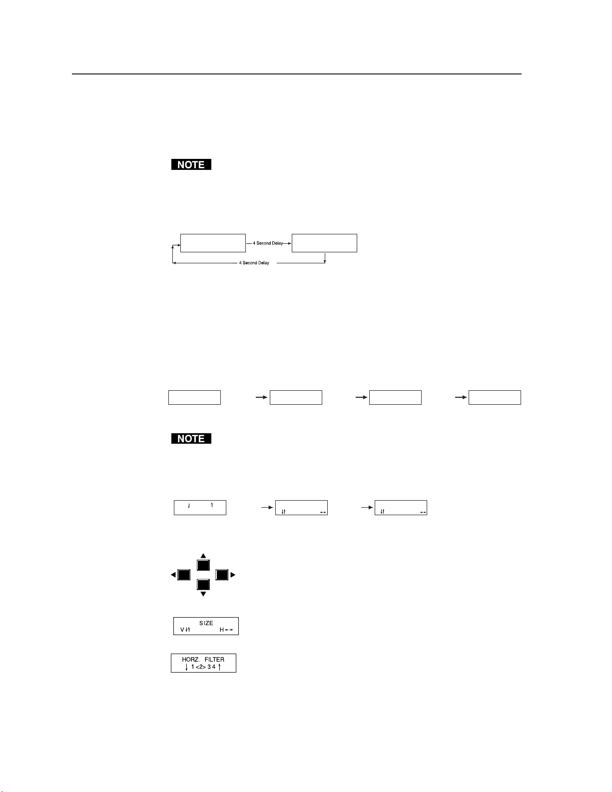
Using the LCD Screen
The scan converter’s LCD screen informs you of status changes, allows you to configure the scan
converter, and provides access to menus that allow you to adjust the image. The screen normally
cycles through two default screens continuously. The first displays the scan converter model, and the
second displays the output frequencies. If the video scan rate is out of range, the default cycle screens
change to “Signal Out of Range” followed by the output frequency screen.
The Menu button allows you to exit the default screens and advance from one menu to the next. The
Next button allows you to step through the adjustment/selection screens within a menu. The front
panel cursor buttons (Up, Down, Left, and Right) can be used from the menu screens to make
adjustments and set parameters. The menu sequence is:
Menu button: Zoom/size/pan controls
Next button: Zoom — Adjust the magnification of an image.
Next button: Size — Adjust the horizontal and vertical dimensions of the image.
Next button: Centering/pan — Shift the horizontal and vertical position of the image.
Menu button: Filter controls
Next button: Horz. filter — Select from any of 4 (VSC 200/200D) or 8 (VSC 300/300D) filters.
Select the filter that improves the image detail the most.
Next button: Vertical filter — Select from any of 5 (VSC 200/200D) or 10 (VSC 300/300D)
filters. Select the filter that reduces the amount of image flicker the most.
Menu button: Configuration controls
Next button: Output res. — Select an output resolution (VSC 300/300D only):
NTSC/PAL, 15 kHz Macintosh, 832 x 624 XGA, 1024 x 768
VGA, 640 x 480 Plasma, 852 x 480 HDTV, 720p
SVGA, 800 x 600
Next button: Output — Select the format used by the output device: SVID (S-video), RGB
(RGsB, RGBS, RGBHV), or YUV (component video; R-Y, G, B-Y).
Next button: Standard — Select NTSC or PAL.
Next button: Encoder filter — Select from any of 3 encoder filters. Select the filter that
provides the sharpest overall image.
Next button: Phase adjust — Adjust the horizontal phase and subcarrier phase. Press Up
or Down to adjust the horizontal phases. Press Left or Right to adjust the subcarrier
phases. See “Setting Up Genlock and Vertical Interval Switching” on page 3-6.
Next button: System reset — Erase all user preset memory. (Resetting does not affect factory
presets.) Press Up and Down simultaneously to continue to the confirm reset
screen, or press Next to cancel the system reset.
Next button: Confirm reset — Confirm that you want to perform a system reset. Press Up
and Down simultaneously to perform the system reset, or press Next to cancel the
system reset.
Front Panel Controls
Centering/pan controls — Shifts the physical position of the displayed image vertically and
horizontally if the default cycle or the centering/pan screen is active.
Freeze/reset — Locks the output display to the current image if the default cycle is active. When the
freeze function is active, the freeze LED is lit. To freeze the image, press the Freeze/reset button
once. To unfreeze the image, press the Freeze/reset button again.
If the zoom, size, or centering/pan screen is active, pressing the Freeze/reset button resets the
adjustments for all three of the screens.
If the horizontal filter, vertical filter, or any output resolution screen is active, pressing the Freeze/reset
button resets the setting of only the active screen.
Executive mode — Makes the LCD menus unavailable. To enable executive mode, press Up and
Down simultaneously. To disable executive mode, press Up and Down simultaneously again.
When executive mode is enabled, the centering/pan controls and the RS-232 port remain active.
Page 5

Table of Contents
Chapter 1 • Introduction ....................................................................................................... 1-1
Features ................................................................................................................................... 1-2
Chapter 2 • Installation .......................................................................................................... 2-1
Front and Rear Panels ....................................................................................................... 2-2
Front panel features .......................................................................................................... 2-2
Rear panel features ........................................................................................................... 2-3
Installation Overview ....................................................................................................... 2-4
Mounting the scan converter ............................................................................................ 2-5
Rack mounting ............................................................................................................. 2-5
Tabletop/desktop placement ........................................................................................ 2-6
Cabling ............................................................................................................................... 2-6
Cable Connector Pin Assignments .............................................................................2-9
Mac-HV/VGA cable ............................................................................................................. 2-9
VGA/13W3 cable ................................................................................................................ 2-9
Mac/13W3 cable ............................................................................................................... 2-10
Chapter 3 • Operation ............................................................................................................. 3-1
Front Panel Operation ...................................................................................................... 3-2
Default screens ................................................................................................................... 3-2
Using the LCD menus ......................................................................................................... 3-2
Zoom/size/pan controls menu ....................................................................................... 3-3
Filter controls menu ............................................................................................................ 3-3
Configuration controls menu ....................................................................................... 3-3
Front panel controls .......................................................................................................... 3-4
Preset Memory ..................................................................................................................... 3-5
Optimizing the Image ....................................................................................................... 3-5
Setting Up Genlock and Vertical Interval Switching ........................................ 3-6
Vertical interval switching setup....................................................................................... 3-6
Genlock setup ....................................................................................................................3-7
Oscilloscope displays .......................................................................................................... 3-8
Chapter 4 • Serial Communication ................................................................................. 4-1
RS-232 Programmer’s Guide .......................................................................................... 4-2
VSC-initiated messages ...................................................................................................... 4-3
VSC error responses ........................................................................................................... 4-3
Using the command/response table ................................................................................. 4-3
Command/response table .................................................................................................. 4-4
Control Software for Windows.................................................................................... 4-5
Installing the software ...................................................................................................... 4-5
Using the software ............................................................................................................ 4-5
VSC 200/200D/300/300D Table of Contents
i
Page 6

Table of Contents, cont’d
Chapter 5 • Troubleshooting .............................................................................................. 5-1
If the image does not appear ........................................................................................... 5-2
If the image is not displayed correctly .............................................................................. 5-2
If the scan converter does not respond to controls ......................................................... 5-3
Appendix A • Specifications .............................................................................................. A-1
VSC 200/200D ....................................................................................................................... A-2
VSC 300/300D ....................................................................................................................... A-3
Appendix B • Reference Information ...........................................................................B-1
Upgrades and Repairs ....................................................................................................... B-2
Internal access ....................................................................................................................B-2
Installing the Digital Module (D-1) upgrade kit ..............................................................B-2
Replacing the AC fuse .......................................................................................................B-4
Installing a firmware update ............................................................................................B-5
Part Numbers ........................................................................................................................ B-6
VSC 200/200D part numbers .............................................................................................. B-6
Related part numbers ................................................................................................... B-6
VSC 300/300D part numbers .............................................................................................. B-6
Related part numbers ................................................................................................... B-6
BNC cables ..........................................................................................................................B-7
Bulk cable .....................................................................................................................B-7
Assorted connectors ..................................................................................................... B-7
Precut cables .................................................................................................................B-7
All trademarks mentioned in this manual are the properties of their respective owners.
ii VSC 200/200D/300/300D Table of Contents
68-396-01 Rev. F
Printed in the USA
05 02
Page 7

VSC 200/200D/300/300D
Chapter One
1
Introduction
Features
Page 8

Introduction, cont’d
Introduction
This manual contains installation, configuration, and operation information for
Extron’s VSC 200, VSC 200D, VSC 300, and VSC 300D scan converters.
The VSC 200 and VSC 300 down-convert computer video to NTSC or PAL format,
which can be recorded, used for videoconferencing, or viewed on an NTSC or PAL
monitor or other display device. The VSC 300 also outputs VGA/SVGA for
display on a PC or Mac monitor.
An optional digital module adds a digital video output. The VSC 200D and the
VSC 300D models include the module, and the VSC 200 and VSC 300 models can
be upgraded to include the module. The upgrade can be performed as a field
upgrade, or the scan converter can be returned to Extron for upgrade.
Features
Autoscanning — Automatically recognizes and converts the incoming computer
image. The VSC 200/VSC 200D supports up to 1280 x 1024 resolution,
70 kHz horizontal and 120 Hz vertical scan rates. The VSC 300/300D
supports up to 1600 x 1280 resolution, 100 kHz horizontal and 120 Hz vertical
scan rates.
NTSC and PAL output — The scan converters are compatible with any display or
recording device that uses the NTSC or PAL standard.
VGA/Mac input — Accepts 15-pin D and HD connectors, allowing easy connection
to most computers. The passive local monitor output allows you to display
the same image on the local monitor as is displayed or recorded on an
external device.
13W3 compatible — Using the VGA/13W3 cable and Mac/13W3 cable that are
provided with the VSC 300/300D, a 13W3 computer and local monitor can be
attached.
High quality zoom control — Uses increased pixel clocking for variable zoom,
providing better quality of the displayed image.
Horizontal and vertical controls — Provides controls for sizing and centering the
image. This provides increased flexibility for panning across the image while
zooming.
Horizontal and vertical filtering — The VSC 200/200D provides four levels of
horizontal and five levels of vertical filter control. The VSC 300/300D
provides eight levels of horizontal and ten levels of vertical filter control.
These user-selectable filtering controls reduce flicker and ensure that no
picture detail is dropped during scan conversion.
High quality color sampling — Uses 24-bit sampling and provide 8 bits per color,
for a total of 16.8 million colors.
Memory presets — Uses approximately 130 memory locations to store presets that
include size, zoom, pan, centering, and filter control settings for various scan
rates. The user can specify 30 of these presets, and the remainder were set at
the factory. The scan converter automatically loads the control settings from
the preset associated with the scan rate of the input video signal.
RS-232 control — Provides control for third-party remote control of features and
functions that can be programmed by using Extron’s Simple Instruction Set™
TM
(SIS
Outputs — Outputs NTSC and PAL video as composite, Y/C (S-video), component
(R-Y, B-Y, Y), and RGBHV. The VSC 300 and VSC 300D also output scalable
SVGA/VGA.
) or Extron’s control software for Windows.
VSC 200/200D/300/300D Introduction1-2
Page 9

Genlock — Allows the integration of the scan converted images into a professional
broadcast environment. Genlocking provides for seamless vertical interval
switching of converted high resolution sources with other video sources.
Digital video output (optional) — Available as standard on the VSC 200D and
VSC 300D, or can be added to the VSC 200 and VSC 300 via the VSC 200/300
D1 Module.
LCD menu display — Informs you of status changes, allows you to configure the
scan converter, and provides access to menus that allow you to adjust the
image.
1-3VSC 200/200D/300/300D Introduction
Page 10

Introduction, cont’d
VSC 200/200D/300/300D Introduction1-4
Page 11

VSC 200/200D/300/300D
Chapter Two
2
Installation
Front and Rear Panels
Installation Overview
Cable Connector Pin Assignments
Page 12

Installation, cont’d
Installation
Front and Rear Panels
Front panel features
9
CENTERING/PAN
MENU
NEXT
1 2 3 4 5 6 7 8
Figure 1 — VSC 200/200D front panel
CENTERING/PAN
MENU
NEXT
1 2 3 4 5 6 7
Figure 2 — VSC 300/300D front panel
Power indicator LED — Lights to indicate that the scan converter is receiving
1
power.
Vertical centering/pan control — Allows you to pan or center the image
2
vertically. See “Front panel controls” on page 3-4 for more information.
Horizontal centering/pan control — Allows you to pan or center the image
3
horizontally. See “Front panel controls” on page 3-4 for more information.
LCD — Displays status information and menu screens. See “Front Panel
4
Operation” on page 3-2 for more information.
GENLOCK
FREEZE/
RESET
COMPUTER TO VIDEO SCAN CONVERTER
9
FREEZE/
RESET
COMPUTER TO VIDEO SCAN CONVERTER
8
VSC 200
10
GENLOCK
VSC 300
10
Menu button — Steps through the LCD menus. See “Using the LCD Menus”
5
on page 3-2 for more information.
Next button — Steps through LCD screens within a menu. See “Using the
6
LCD Menus” on page 3-2 for more information.
Cursor buttons — Allow you to adjust the image and select video
7
parameters. See “Using the LCD Menus” on page 3-2 for more information.
Freeze/reset button — Freezes/unfreezes the displayed image, or resets the
8
zoom and size values. See “Front panel controls” on page 3-4 for more
information.
Freeze LED — Lights to indicate the that the freeze feature is active.
9
Genlock LED — Lights to indicate that a valid reference signal is present on
10
the genlock input BNC. See “Setting Up Genlock and Vertical Interval
Switching” on page 3-6.
VSC 200/200D/300/300D Installation2-2
Page 13

Rear panel features
19
100-240
100-240
50/60 Hz 0.5A
1
50/60 Hz 0.5A
1
INPUT/LOOP OUT
MAC
2
D1
VGA
3
VIDEO
5
4
7
S-VIDEO
9
R/R-Y G/Y B/B-Y H/HV
10 11 12 13
8
OUTPUTS
G
E
H
HV
V
SOG
16
15
N
L
O
C
K
14
Figure 3 — VSC 200/200D rear panel
INPUT/LOOP OUT
MAC
2
D1
VGA
3
VIDEO
4
5
6
S-VIDEO
7
9
8
R/R-Y G/Y B/B-Y H/HV
10
OUTPUTS
H
HV
V
SOG
13
15
12
11
16
VGA OUT
17
G
E
N
L
O
C
K
18
14
Figure 4 — VSC 300/300D rear panel
AC power connector — Standard AC power connector attaches the scan
1
converter to any power source from 100VAC to 240VAC, operating at 50 Hz or
60 Hz.
15-pin D connector — Mac input/loop out (loop through) computer video
2
connector.
IN
RS-232
OUT
REMOTE
20
21
19
IN
RS-232
OUT
REMOTE
21
20
15-pin HD connector — VGA input/loop out (loop through) computer video
3
connector.
75 ohm/Hi-Z switch — Provides termination for computer video input. Set
4
the switch to 75
ΩΩ
Ω if no local monitor is attached to the scan converter. Set the
ΩΩ
switch to Hi-Z if a local monitor is attached.
Composite video output connector
5
Composite video LED (VSC 300/300D only) — Lights to indicate that the
6
composite video output is active.
Digital video output (ITU-R BT.601) connector (VSC 200D/300D only) —
7
Follows composite video out: If composite video is active, digital video is
active.
S-video output connector
8
S-video LED — Lights to indicate that the S-video output is active.
9
R/R-Y output connector — Red video output (RGB) or R-Y video output
10
(component video).
G/Y output connector — Green video output (RGB) or Y video output
11
(component video).
B/B-Y output connector — Blue video output (RGB) or B-Y video output
12
(component video).
H/HV output connector — Horizontal sync output (RGBHV) or composite
13
sync output (RGBS).
2-3VSC 200/200D/300/300D Installation
Page 14

Installation, cont’d
RGB/R-Y, Y, B-Y LED — Lights to indicate that the RGB or component video
14
output is active.
Sync selection switch — Allows you to choose how the sync output signals
15
for RGsB/RGBS/RGBHV are routed:
H — If the switch is set to H, the scan converter outputs separate horizontal
HV — If the switch is set to H/V, the scan converter outputs a composite sync
SOG — If the switch is set to SOG (sync on green), the scan converter outputs
V output connector — Vertical sync output (RGBHV).
16
15-pin VGA output connector (VSC 300/300D only) — Scaled VGA output.
17
VGA LED (VSC 300/300D only) — Lights to indicate that the VGA output is
18
active.
Component video (R-Y, Y, B-Y) is referred to as YUV in the front panel LCD
menus.
and vertical sync signals; only horizontal sync is routed through the
H/HV output connector.
signal (H and V combined) on the H/HV output connector.
a composite sync signal on the green video signal via the G/Y output
connector.
Genlock input connector — Genlock reference signal input.
19
Genlock output connector — Passes the genlock reference signal to the next
20
device. If the signal is not passed to another device, connect a 75-ohm
termination adapter.
RS-232 connector — 9-pin D female connector that allows you to attach a
21
computer or controlling device for remote control of the scan converter.
Installation Overview
To install the scan converter, follow these general steps:
If desired, mount the scan converter in a rack (see “Mounting the scan
1
converter” on page 2-5). Otherwise, install the rubber feet (see “Tabletop/
desktop placement” on page 2-6).
Turn off power to the input and output devices, and unplug the power cables
2
from them.
Attach the input device and the output device to the scan converter. See
3
“Cabling” on page 2-6.
Set the configuration switches.
4
Plug the scan converter, input device, and output device into a grounded AC
5
source.
Turn on the input and output devices.
6
Use the LCD menu screens to configure the scan converter. See “Front Panel
7
Operation”, page 3-2.
The image from the input device should appear on the output device. If it
8
does not, double check steps 3 and 4 and make adjustments as needed. See
chapter 5 for additional assistance.
Optimize the image for your display environment. See “Optimizing the
9
image” on page 3-5.
VSC 200/200D/300/300D Installation2-4
Page 15

Mounting the scan converter
The scan converter ships with four uninstalled rubber feet. If you are going to rack
mount the unit, do so before cabling the unit, and do not install the rubber feet. If
you are not rack mounting the scan converter, skip to “Tabletop/desktop
placement” on page 2-6.
Rack mounting
To rack mount the scan converter, do the following:
1. Attach the mounting brackets (supplied with the scan converter) on either
side of the scan converter, as shown in figure 5. Use four screws per
mounting bracket.
INPUT/LOOP OUT
MAC
OUT
VGA OUT
OUTPUTS
VGA
A
5
.
0
#8 Screw (4 Plcs) Each Side
z
H
0
6
/
0
5
0
4
2
-
0
0
1
Figure 5 — Installing mounting brackets
C
E
N
T
E
R
IN
G
/P
A
N
G
E
N
L
O
C
M
E
N
U
N
E
X
T
K
F
R
E
E
Z
E
/
R
E
S
E
T
VSC 200
C
O
M
P
U
T
E
R
T
O
V
ID
E
O
S
C
A
N
C
O
N
V
E
R
T
E
R
Figure 6 — Mounting the scan converter
2. Using two screws per mounting bracket, attach the scan converter to the rack
as shown in figure 6.
2-5VSC 200/200D/300/300D Installation
Page 16

Installation, cont’d
Tabletop/desktop placement
For tabletop or desktop placement, install the self-adhesive rubber feet/pads
(provided) onto the four corners of the bottom of the enclosure.
Cabling
The scan converter connects to a source computer, such as a Macintosh or
VGA-type personal computer or a Sun workstation, and to an output device, such
as a video recorder, videoconferencing system, CRT monitor, or LCD projector.
Figure 10 shows the entire system as it looks after it is hooked up.
1. For a Mac or VGA-type PC, connect the local monitor to its corresponding
(Mac or VGA) 15-pin input/ loopout connector on the scan converter’s rear
panel, using the monitor’s video cable.
For a Sun workstation, connect the 13W3 end of the VGA/13W3 cable
(provided with the VSC 300/300D) to the local monitor, and connect the VGA
end to the HD 15-pin input/loopout connector (VGA).
2. For a Mac or VGA-type PC, connect the computer to the scan converter’s
other input connector, using the included Mac-VGA cable. See figure 7 and
the pin assignment information on page 2-9.
• If the source computer is a Macintosh, plug the VGA (15-pin HD) end of
• If the source computer is a VGA-type PC, plug the Mac (15-pin D) end of
the Mac-VGA cable into the scan converter, and plug the other (15-pin D)
end into the computer’s video output connector.
the Mac-VGA cable into the scan converter, and plug the other
(15-pin HD) end into the computer’s video output connector.
INPUT/LOOP OUT
INPUT/LOOP OUT
MAC
VGA
MAC
VGA
PC Input Mac Input
Figure 7 — Mac-VGA cable local monitor connections
For a Sun workstation, connect the 13W3 end of the Mac/13W3 cable
(provided with the VSC 300/300D) to the computer, and connect the Mac end
to the 15-pin D connector (Mac; figure 8).
INPUT/LOOP OUT
MAC
VGA
Sun/SGI Input
Figure 8 — Sun workstation local monitor connections
VSC 200/200D/300/300D Installation2-6
Page 17

If a local monitor will not be used, set the 75 ohm/Hi Z switch to 75 Ω.
If no input signal is present, by default the output display is blank. However,
using RS-232 commands, you can set the scan converter to display
NTSC/PAL composite video color bars when no input signal is present. See
the command/response table on page 4-4 for details.
3. Connect a composite video display or recording device to the composite video
DIGITAL
OUT
VIDEO
R/R-Y G/Y B/B-Y H/HV
S-VIDEO
Composite
H
HV
VGA OUT
V
SOG
output connector.
4. Select the format of the second output using the output configuration menu.
If RGB video, set the sync selection switch.
5. Connect a cable from the input of the second video display or recording
device (projector, monitor, VCR, etc.) to the appropriate rear panel output
connectors on the scan converter.
Only one of the following is available at a time.
S-video — Connect a coax cable to the S-video connector.
DIGITAL
OUT
S-VIDEO
R/R-Y G/Y B/B-Y H/HV
S-video
VIDEO
H
HV
VGA OUT
V
SOG
Digital video (VSC 200D and 300D only) — Connect a coax cable to the D1
DIGITAL
OUT
VIDEO
R/R-Y G/Y B/B-Y H/HV
S-VIDEO
Digital
H
HV
VGA OUT
V
SOG
connector.
Component video — Connect coax cables to the R/R-Y, G/Y, and B/B-Y
DIGITAL
OUT
VIDEO
R/R-Y G/Y B/B-Y H/HV
S-VIDEO
Component
H
HV
VGA OUT
V
SOG
connectors.
RGsB — Connect coax cables to the R/R-Y, G/Y, and B/B-Y connectors.
DIGITAL
OUT
VIDEO
R/R-Y G/Y B/B-Y H/HV
S-VIDEO
RGsB
H
HV
VGA OUT
V
SOG
RGBS — Connect coax cables to the R/R-Y, G/Y, B/B-Y, and H/HV
DIGITAL
OUT
VIDEO
R/R-Y G/Y B/B-Y H/HV
S-VIDEO
RGBS
H
HV
VGA OUT
V
SOG
(composite sync) connectors.
RGBHV — Connect coax cables to the R/R-Y, G/Y, B/B-Y, H/HV, and V
DIGITAL
OUT
VIDEO
R/R-Y G/Y B/B-Y H/HV
S-VIDEO
RGBHV
H
HV
VGA OUT
V
SOG
connectors.
Scaled VGA — Connect a 15-pin HD cable to the scan converter’s 15-pin HD
DIGITAL
OUT
VIDEO
R/R-Y G/Y B/B-Y H/HV
S-VIDEO
Scaled VGA
H
HV
VGA OUT
V
SOG
connector (VSC 300/300D only).
Connect cables for only one output in addition to the composite video
output. Do not connect cables to the outputs that will not be used for your
application. Connecting cables to more outputs will overload the circuits
and yield weak signals.
2-7VSC 200/200D/300/300D Installation
Page 18

Installation, cont’d
6. Connect the coax cable from the genlock device (or the genlock output of
another device that shares the genlock signal) to the Genlock In connector. If
no genlock device will be used, do not attach cables to these connectors.
If another device in the system will use genlock, connect the device to the
Genlock Out connector (figure 9). Otherwise, attach a termination adapter to
the Genlock Out connector. If the genlock signal is connected to several
devices in a daisy chain configuration, the last device must provide genlock
termination. See “Setting Up Genlock and Vertical Interval Switching” on
page 3-6.
Figure 9 — Connecting genlock
7. If RS-232 control will be used, connect the RS-232 remote control or computer
to the RS-232 connector.
8. Connect power cords and turn on all equipment.
Figure 10 shows typical system installation and cable connections.
G
E
N
L
O
C
K
OUT
OUT
Timing Source
IN
RS-232
REMOTE
VSC 200
Rear Panel
IN
G
E
N
L
OUT
O
C
K
or Other Device
RS-232
REMOTE
VSC 200
IN
To Next Device
or Terminate
External
T
U
O
T
S
U
T
O
A
PU
T
U
VG
O
T
U
O
P
O
O
/L
T
U
P
IN
A
G
V
C
A
M
A
5
.
0
z
H
0
6
/
0
VSC 300
5
0
4
2
0
0
1
or or
Sun/SGI Input
Mac InputVGA Input
and other High-Resolution Computers and Workstations
Genlock
Timing
Composite
S-Video
Video
RS-232 Control
LCD Projector
Betacam
Tape Deck
Video Outputs
VCR
Videoconferencing
System
or
Monitor
Figure 10 — Typical scan converter application
See the next chapter, “Operation”, for information on configuring and using the
scan converter.
VSC 200/200D/300/300D Installation2-8
Page 19

Cable Connector Pin Assignments
Mac-HV/VGA cable
Figure 11 shows the pin locations on the 15-pin connectors at opposite ends of the
Mac-HV/VGA cable that is used for connecting a computer to the scan converter.
HD15 Connector
Male
610
51
DB15 Connector
Male
81
1511
159
Figure 11 — VGA (HD15) and Mac (DB15) connector pin locations
The table below lists signals and their pin assignments for the
VGA (15-pin HD) and Mac (15-pin D) connectors of this cable.
VGA Pin Function Mac Pin
1 Red video 2
2 Green video 5
3 Blue video 9
4 ID bit 4
5 ID bit 8
6 Red ground 1
7 Green ground 6
8 Blue ground 13
9 Not used —
10 Composite & vertical sync gnd 11, 14
11 ID bit 7
12 ID bit 10
13 Horizontal sync 15
14 Vertical sync 12
15 ID bit/composite sync 3
VGA/13W3 cable
Figure 12 shows the pin locations on the 13W3 and 15-pin connectors at opposite
ends of the VGA/13W3 cable that is used for local monitor loop-through
(VSC 300/300D).
13W3 Connector
Female
15
610
Figure 12 — 13W3 and VGA (HD15) connector pin locations
The table on the next page lists signals and their pin assignments for the 13W3 and
VGA (15-pin HD) connectors of this cable.
HD15 Connector
A2 A3A1
Male
610
51
1511
2-9VSC 200/200D/300/300D Installation
Page 20

Installation, cont’d
13W3 Pin Function VGA Pin
A1 Red video 1
Gnd Red ground *6
A2 Green video 2
Gnd Green ground *7
A3 Blue video 3
Gnd Blue ground *8
1 ID bit 4
2 Ground *10
3 ID bit 5
4 ID bit ground *10
5 Composite sync 13
6 ID bit 11
7 ID bit 12
8 ID bit 14
9 ID bit 15
10 Composite sync ground *10
* The ground pins are shorted together, then connected to the shell.
Mac/13W3 cable
Figure 13 shows the pin locations on the 13W3 and 15-pin connectors at opposite
ends of the Mac/13W3 cable that connects the computer to the scan converter
(VSC 300/300D).
13W3 Connector
A2A3 A1
Male
DB15 Connector
Male
15
81
610
159
Figure 13 — Mac (DB15) and 13W3 connector pin locations
The table below lists signals and their pin assignments for the 13W3 and Mac
(15-pin D) connectors of this cable.
13W3 Pin Function Mac Pin
A1 Red video 2
Gnd Red ground *1
A2 Green video 5
Gnd Green ground *6
A3 Blue video 9
Gnd Blue ground *13
1 ID bit 4
2 Ground *11
3 ID bit 8
4 ID bit ground *11
5 Composite sync 15
6 ID bit 7
7 ID bit 10
8 ID bit 12
9 ID bit 3
10 Composite sync ground *14
* The ground pins are shorted together, then connected to the shell.
VSC 200/200D/300/300D Installation2-10
Page 21

VSC 200/200D/300/300D
Chapter Three
3
Operation
Front Panel Operation
Preset Memory
Optimizing the Image
Setting Up Genlock and Vertical Interval Switching
Page 22
Operation, cont’d
Operation
Front Panel Operation
The front panel includes an LCD screen that displays the current status of the scan
converter and the scan rate of the current video input signal. You can also use
controls on the front panel to configure the scan converter and control the image
display.
Default screens
By default, the LCD toggles between two screens every four seconds. One screen
displays the product name, and the other shows the input frequencies (figure 14
shows an example).
EXTRON VSC 200
Scan Converter
Figure 14 — Default screens
Using the LCD menus
The LCD menus and front panel controls allow you to configure the scan converter
and make adjustments to the displayed image.
To access the menus, press the Menu button on the front panel. The zoom/size/pan
controls menu appears in the LCD screen. If you want to display a different menu,
press and release the Menu button until the desired menu appears
(figure 15).
ZOOM/SIZE/PAN
CONTROLS
Diagrams of the front panels are shown on page 2-2.
Horz. 00.00 kHz
Vert. 00.00 Hz
Menu button
FILTER
CONTROLS
Menu button
CONFIGURATION
CONTROLS
Menu button
EXIT
MENU
Figure 15 — Selecting a menu
If the signal is out of range, the LCD menus are not available.
After you have selected the desired menu, press the Next butt on to access the
screens that are available within the menu. If you want to display a different
screen, press and release the Next button until the desired screen appears
(figure 16).
ZOOM
Next button
SIZE
V H
Next button
CENTERING/PAN
V H
Figure 16 — Selecting a screen
You can press the front panel cursor buttons (Up, Down, Left, and Right) to make
adjustments or selections from the menu screens. The menu
screens display arrows to indicate the cursor buttons that apply
to that adjustment or selection.
For example, the size screen indicates that the Up and Down buttons increase or
decrease the vertical (V) size, and the Left and Right buttons
decrease and increase the horizontal (H) size.
The horizontal filter screen indicates that you can press the Up and Down buttons to
change the filter selection. The current selection appears in
brackets.
You can press the cursor buttons from the default screens to center the displayed
output image.
VSC 200/200D/300/300D Operation3-2
Page 23

Zoom/size/pan controls menu
Zoom — Changes the magnification of the image. Press the Up cursor button to
zoom in, or press the Down button to zoom out.
Size — Increases or decreases the vertical and horizontal dimensions of the
displayed image. Press the Up cursor button to increase the vertical size of
the image, or press the Down button to decrease the vertical size. Press the
Left cursor button to decrease the horizontal size of the image, or press the
Right button to increase the horizontal size.
Centering/pan — Shifts the physical position of the displayed image vertically and
horizontally. Press the Up cursor button to shift the image up, or press the
Down button to shift it down. Press the Left cursor button to shift the image
to the left, or press the Right button to shift the image to the right.
Filter controls menu
Horizontal filter — Applies one of the available filters to improve the detail of the
image. The VSC 200/200D provides four levels, and the VSC 300/300D
provides eight levels, of horizontal filter control. Press the Up or Down
cursor buttons to move through the filters. Choose the filter that provides the
most improvement to the image detail.
Vertical filter — Applies one of the available filters to decrease flicker in the image.
The VSC 200/200D provides five levels, and the VSC 300/300D provides ten
levels, of vertical filter control. Press the Up or Down cursor buttons to move
through the filters. Choose the filter that provides the greatest reduction of
flicker while maintaining image sharpness.
Configuration controls menu
Output resolutions (VSC 300/300D only) — Specifies the resolution used by the
output device. Press the Up or Down cursor buttons to move through the
resolutions:
• NTSC/PAL, 15.75 kHz
• VGA, 640 x 480
• SVGA, 800 x 600
• Macintosh, 832 x 624
• Plasma, 852 x 480
• XGA, 1024 x 768
• HDTV, 720p
For any choice other than NTSC/PAL, only the VGA 15-pin HD output
connector can be used.
Output — Specifies the format used by the output device. Press the Left or Right
cursor buttons to move through the formats:
• SVID (S-video)
• RGB (RGsB, RGBS, or RGBHV)
• YUV (component video; R-Y/G/B-Y)
Standard — Specifies the video standard used by the output device. Press the Left
or Right cursor buttons to move through the standards:
• NTSC
•PAL
3-3VSC 200/200D/300/300D Operation
Page 24

Operation, cont’d
Encoder filter — Applies one of the encoder filters to improve the overall image
sharpness. Press the Left or Right cursor buttons to move through the filters:
• STD
• KIL3.58
•HI
Phase adjust — Adjusts the signal’s horizontal phase (the phasing between the
horizontal sync pulses of the video output and the genlock sync pulses) and
subcarrier phase (the phasing between the color burst signal of the video
output and the genlock color burst signal). Press the Up or Down cursor
buttons to adjust the horizontal phase, or press the Left or Right cursor
buttons to adjust the subcarrier phase. See “Setting Up Genlock and Vertical
Interval Switching” on page 3-6 for more information.
System reset — Erases all user preset memory. This has no effect on the factory
preset memory. Press the Up and Down cursor buttons simultaneously to
reset the system, and the confirm reset screen appears. Or, press the Next
button to cancel the system reset.
Confirm reset — Allows you to confirm that you want to erase all user preset
memory. Press the Up and Down cursor buttons simultaneously to reset the
system, or press the Next button to cancel the system reset. If you press the
Up and Down buttons, the user preset memory is erased.
If you previously issued an RS-232 command to enable NTSC/PAL composite
video color bars, performing a system reset will disable the color bars. To reenable the color bars, issue the RS-232 command again (see the command/
response table on page 4-4 for more information).
Front panel controls
Centering/pan controls — Shift the physical position of the displayed image
CENTERING/PAN
Freeze/reset — Locks the output display to the current image if the default cycle is
active. When freeze mode is active, the freeze LED is lit. To freeze the image,
press the Freeze/reset button once. To unfreeze the image, press the Freeze/
reset button again. No front panel adjustments can be made until freeze
mode is inactive.
If the zoom, size, or centering/pan screen is active, pressing the Freeze/reset
button resets adjustments for all three of the screens.
If any other screen is active, pressing the Freeze/reset button resets the
setting for only the active screen.
Executive mode — Makes the LCD menus unavailable. This is useful for situations
in which many end users operate the scan converter, and you want to prevent
them from changing the adjustments you have made. To enable executive
mode, press the Up and Down cursor buttons simultaneously while the
default cycle is active. To disable executive mode, press the Up and Down
buttons simultaneously again.
When executive mode is enabled, the centering/pan controls, Freeze/reset
button, and RS-232 port remain active.
vertically and horizontally if the default cycle or the centering/
pan screen is active.
VSC 200/200D/300/300D Operation3-4
Page 25

Preset Memory
FILTER
CONTROLS
ZOOM/SIZE/PAN
CONTROLS
Menu button
CONFIGURATION
CONTROLS
Menu button
OUTPUT RES.
xxxxxxxx
Next button
OUTPUT
SVID <RGB> YUV
Next button
STANDARD
<NTSC> PAL
Next button
Menu button
The scan converter preset memory contains 130 locations that store scan rates and
associated size, zoom, pan, centering, and filter controls. The 30 user presets can be
changed or erased. The remaining locations are factory-loaded, permanent presets
that cannot be changed or erased.
When a video input is connected, the scan converter automatically scans the user
presets and then the factory presets, looking for a match to the input scan rate. If a
match is found, the stored settings become the active settings. If no match is found,
a user preset is created automatically using the default settings. If the user preset
memory is full, the new user preset overwrites the oldest user preset.
If a user preset is active and changes are made to the zoom, size, pan, or filter
controls, the changed settings are stored automatically in the preset memory for the
active scan rate. If a factory preset is used and changes are made to the zoom, size,
pan, or filter controls, a new user preset that includes the new settings is created.
To reset all user presets, perform a system reset (see page 3-4).
Preset memory does not include selections from the configuration controls
menu. The scan converter uses only the most recently applied configuration
controls selections.
Optimizing the Image
Follow the procedures in this section, in sequence, after you have installed the scan
converter. This will help you configure the scan converter for the best settings for
your display environment.
1. Select the output standard:
a. Press and release the Menu button until the configuration controls menu
appears.
b. Press and release the Next button until the standard screen appears.
c. Press the Left or Right cursor button to select NTSC or PAL.
Figure 17 — Selecting the output standard
2. Size the image to fill the screen:
a. Press and release the Menu button.
b. Press and release the Next button.
c. Press the Left or Right cursor buttons until the image fills the width of
the screen. Press the Up or Down cursor buttons until the image fills the
height of the screen.
Turn the rotary knobs to keep the image centered while sizing it.
Menu button
ZOOM/SIZE/PAN
CONTROLS
Next button
ZOOM
Next button
SIZE
V H
Figure 18 — Sizing the image
3-5VSC 200/200D/300/300D Operation
Page 26

Operation, cont’d
3. Select the filters:
a. Press and release the Menu button until the filter controls menu appears.
b. Press the Next button.
c. Press the Up or Down cursor buttons to select the horizontal filter that
d. Press the Next button.
e. Press the Up or Down cursor buttons to select the vertical filter that
provides the most improvement to the image detail. You can use an
alternating pixel pattern to perform this adjustment.
provides the greatest reduction of flicker while maintaining image
sharpness. You can use an image pattern of horizontal lines, such as a
crosshatch, to perform this adjustment.
Menu button
HORZ. FILTER
1 <2> 3 4
ZOOM/SIZE/PAN
CONTROLS
Next button
Menu button
VERTICAL FILTER
0 1 <2> 3 4
FILTER
CONTROLS
Next button
Figure 19 — Selecting the filters
If the filters are set before the image size is adjusted, you must set the filters
again after adjusting the image size.
4. Select the encoder filter:
a. Press and release the Menu button until the configuration controls menu
appears.
b. Press and release the Next button until the encoder filter screen appears.
c. Press the Left or Right cursor buttons to select the encoder filter that
provides the sharpest overall image. You can use a text pattern to
perform this adjustment.
Menu button
OUTPUT RES.
xxxxxxxx
ZOOM/SIZE/PAN
CONTROLS
Next button
Menu button
OUTPUT
SVID <RGB> YUV
FILTER
CONTROLS
Next button
Menu button
STANDARD
<NTSC> PAL
CONFIGURATION
CONTROLS
Next button
Next button
ENCODER FILTER
STD <KIL3.58> HI
Figure 20 — Selecting the encoder filter
Setting Up Genlock and Vertical Interval Switching
A genlock (black burst generator) device can be connected to the scan converter to
synchronize it with other system components for seamless vertical interval
switching between sources.
Vertical interval switching setup
For vertical interval switching (to allow clean switching between signals from
several devices during the vertical blanking period of each signal), a composite
sync signal can be applied at the Genlock In connector, and also passed to another
device via the Genlock Out connector.
VSC 200/200D/300/300D Operation3-6
Page 27

If the genlock connectors are used only for vertical interval switching, no horizontal
or subcarrier phase adjustments are required, and the genlock LED does not light.
Genlock setup
Genlock differs from simple vertical interval switching in that an external device (a
black burst generator) generates a reference sync signal for the system, and every
device that uses that signal has its output signal’s horizontal and subcarrier phases
adjusted to exactly match that of the generator to allow precise timing and full
synchronization. Genlocked systems produce cleaner switches between inputs
than do those without this type of synchronization.
An oscilloscope is required for genlock setup, and a vectorscope is recommended.
Waveform monitors of types other than a vectorscope may give the appearance that
timing is adjusted correctly when it is 180 degrees out of phase, which will result in
incorrect colors or picture artifacts.
To synchronize the scan converter’s video output with a genlock signal, follow
these steps:
1. Power up and turn on all the devices that will use the genlock signal. The
devices must be on for at least 15 to 20 minutes before proceeding with any
adjustments.
2. Connect the active timing source signal to the Genlock In connector on the
rear panel (figure 21).
50/60 Hz 0.5A
100-240
All equipment in the system must be powered up and turned on for at least 15
to 20 minutes before genlock setup adjustments can be made and before the
equipment is used in a genlocked application.
Timing Source
OUT
Computer Video
Signal In
INPUT/LOOP OUT
MAC
DIGITAL
OUT
VGA
VIDEO
R/R-Y G/Y B/B-Y H/HV
S-VIDEO
H
HV
V
SOG
IN
G
E
N
RS-232
L
OUT
O
C
K
REMOTE
To Scope Probe B
To Scope Probe A
and Termination
Figure 21 — Cable connections for genlock setup
3. Connect the active computer video input signal to the appropriate input as
explained in step 2 of the cabling section on page 2-6. Ensure that the input is
properly terminated either by connecting a local monitor to the other input/
loopout (loop through) connector, or by setting the 75 ohm/Hi Z switch to
75Ω. The Genlock LED lights to indicate that the scan converter is receiving
an acceptable genlock (black burst) sync signal via the Genlock In connector.
4. Connect oscilloscope (“scope”) probe A to the Genlock Out connector. This
will provide the scope’s reference signal. In order to avoid altering the
genlock signal, use the cabling configuration that will be used in the
installation. Either connect the genlock signal cable from the scope to the next
device in the system to be timed, or provide 75 ohm termination at the scope’s
genlock output.
5. Connect scope probe B to the scan converter’s composite video output
connector. Ensure that the standard screen of the configuration controls menu is
set to the desired standard (NTSC or PAL; see page 3-3).
3-7VSC 200/200D/300/300D Operation
Page 28

Operation, cont’d
6. Using the instructions for the scope you are using, set the scope to view the
signals’ horizontal phases. From the phase adjust screen of the configuration
controls menu, adjust the scan converter’s horizontal phase control until there
is no (0º) difference between the composite video output’s horizontal sync
phase and the genlock signal’s horizontal phase. See “Oscilloscope displays”
on page 3-8, and “Configuration controls menu” on page 3-3.
7. Set the scope to view the subcarrier signals. From the phase adjust screen of
the configuration controls menu, adjust the scan converter’s subcarrier phase
until there is a zero phase difference between the genlock signal and the
NTSC/PAL output. The Genlock LED should light.
8. View the horizontal phases again. If the phase difference is not zero, repeat
steps 6 and 7 until the settings do not change.
9. After the settings are stable and the Genlock LED lights, disconnect the
oscilloscope, and reconnect the genlock cables and terminator to the proper
devices in the system.
10. Check the display for proper colors and for undesirable artifacts in the image.
Make adjustments as necessary. After the genlock timing has been adjusted, it
should not require readjustment when changing to a new computer video
signal input.
11. If other scan converters are part of this genlock daisy chain, connect the
oscilloscope to each device, and repeat this procedure.
If the Genlock LED does not light at this point, either adjust the horizontal or
subcarrier phases further, or use a different genlock source.
The subcarrier adjustment range is +/- 180 degrees from 0 for a total
adjustment range of 360 degrees.
If the Genlock LED does not light at all when genlock is active and the
horizontal and subcarrier phases have been adjusted to match the genlock
signal, do not continue with this procedure. A different, more stable or timebase-corrected sync signal must be used for the genlock timing source.
Oscilloscope displays
What you see on the oscilloscope while adjusting the scan converter to match the
genlock signal depends on the type of signal used, the type of oscilloscope, and the
procedure the scope requires. This section shows some examples of oscilloscope
displays.
Figure 22 shows the genlock input signal (top) and an out-of-alignment NTSC
composite sync output signal (bottom) displayed on a waveform monitor to check
for alignment. When the phases are aligned, the wave peaks on the bottom
waveform should line up with those in the reference signal above it.
VSC 200/200D/300/300D Operation3-8
Page 29

With this method there is no way to know if the signals are 180º out of phase. A
delayed sweep on a time-based scope would allow a more accurate display of the
input and output signal phase relationships.
Figure 22 — Superimposed waveforms
0
350
340
330
320
310
300
290
280
270
260
250
240
230
220
210
200
190
10
20
30
40
50
60
70
80
90
100
110
120
130
140
150
160
170
180
3-9VSC 200/200D/300/300D Operation
Page 30

Operation, cont’d
A vectorscope is more accurate than a waveform monitor. Figure 23 shows an
example of a vectorscope display when the horizontal phase is adjusted to align it
with the burst (genlock) vector. Adjust the horizontal phase until the difference
+40
A1
A2
A3
B1
B2
-40
B3
0
350
340
330
320
310
300
290
280
270
260
250
240
230
220
210
200
190
10
20
30
40
50
60
70
80
90
100
110
120
130
140
150
160
170
180
between the two vectors is 0º. This example shows black burst only (with no color).
The burst vector is pointing to the left from the center.
Figure 23 — Vectorscope screen during horizontal phase adjustment
Figure 24 shows an example of a view of a vectorscope during adjustment of the
color subcarrier phase. The subcarrier phase should be aligned to 0º (indicated in
the figure by the triangle).
Figure 24 — Vectorscope screen during color subcarrier phase
adjustment
VSC 200/200D/300/300D Operation3-10
Page 31

VSC 200/200D/300/300D
Chapter Four
4
Serial Communication
RS-232 Programmer’s Guide
Control Software for Windows
Page 32

Serial Communication, cont’d
Serial Communication
The scan converter’s RS-232 connector can be connected to the serial port output of
a host device such as a computer or control system. This connection makes
software control of the scan converter possible. Figure 25 shows a scan converter
RS-232 connection to a host serial port connector.
U
O
T
U
O
T
S
U
T
O
U
A
P
T
G
V
T
U
O
P
O
O
/L
T
U
P
IN
A
G
V
C
A
M
z 0.5A
0 H
/6
50
40
00-2
1
RS-232
Control Cable
Computer Control
Figure 25 — Scan converter RS-232 to host connection
The RS-232 connector on the scan converter is a 9-pin D female connector with the
following pin assignments:
Pin Description
1 Not used
2 Transmit data
3 Receive data
4 Not used
5 Signal ground
6 Not used
7 Not used
8 Not used
9 Not used
The protocol is 9600 baud, 8-bit, 1 stop bit, no parity, and no flow control.
RS-232 Programmer’s Guide
The scan converter accepts SIS (Simple Instruction Set) commands through the
RS-232 port. SIS commands consist of one or more characters per command field.
They do not require any special characters to begin or end the command character
sequence. Each scan converter response to an SIS command ends with a carriage
return and a line feed (CR/LF =
character string. A string is one or more characters.
VSC 200/200D/300/300D Serial Communication4-2
), which signals the end of the response
Page 33

VSC-initiated messages
When a local event such as a front panel operation occurs, the scan converter
responds by sending a message to the host. The VSC-initiated messages are listed
below (underlined).
(C) Copyright 1998-1999, Extron Electronics, VSC 200/300, Vx.xx
The copyright message is initiated by the scan converter when it is first powered
on. Vx.xx is the firmware version number.
Reconfig
The Reconfig message is initiated by the scan converter when the resolution of the
input signal is changed and when the front panel LCD menus are exited, indicating
that there may have been a change to the adjustments or parameters.
The scan converter does not expect a response from the host, but, for example, the
host program might request a new status.
VSC error responses
When the scan converter receives an SIS command and determines that it is valid, it
performs the command and sends a response to the host device. If the scan
converter is unable to perform the command because the command is invalid or
contains invalid parameters, the scan converter returns an error response to the
host. The error response codes are:
E09 — Invalid function number (too large)
E10 — Invalid command
E13 — Invalid value (out of range)
Using the command/response table
The command/response table is shown on the next page. Lower case characters
are acceptable in the command field only where indicated. Symbols are used
throughout the table to represent variables in the command/response fields.
Symbol definitions are shown at the beginning of the table, as is an ASCII-tohexadecimal conversion table. Command and response examples are shown
throughout the table.
4-3VSC 200/200D/300/300D Serial Communication
Page 34

Serial Communication, cont’d
Command/response table
Symbol Definitions:
ASCII to HEX Conversion Table
Space
= CR/LF, • = space
X1
= Horizontal VSC 200: 1–4
filtering level VSC 300: 1–8
X2
= Vertical VSC 200: 0–4
filtering level VSC 300: 0–9
X3
= Input 1 = S-video
2 = RGB
3 = Component
X4
=Output 1 = NTSC
2 = PAL
3–8 Scaled output resolutions (VSC 300 only)
3 = 640x480
4 = 800x600
5 = 832x624
6 = 852x480
X5
= 1 = On, 0 = Off
X6
= xxx.xx Hrt = Horizontal rate = kHz
7 = 1024x768
8 = 720p
= xxx:xx Signal out of range
COMMAND ASCII RESPONSE DESCRIPTION
Horizontal Shift
Shift Right {H Hph+
Shift Left }H Hph–
Shift image right one step
Shift image left one step
Vertical Shift
Shift Down {/ Vph+
Shift Up }/ Vph–
Shift image down one step
Shift image up one step
Horizontal Size
Increase Size {: Hsz+
Decrease Size }: Hsz–
Increase horizontal size by one step
Decrease horizontal size by one step
Vertical Size
Increase Size {; Vsz+
Decrease Size }; Vsz–
Increase vertical size by one step
Decrease vertical size by one step
Zoom
Zoom In {+ Zom+
Zoom Out }+ Zom–
Increase image size by one step
Decrease image size by one step
Horizontal Filter (Detail)
X1
Specific Value
DDhz
Increment Up {D Dhz
Increment Down }D Dhz
X1
X1
X1
Select horizontal filter X1 (Dhz)
Select next higher horizontal filter (Dhz + 1)
Select next lower horizontal filter (Dhz – 1)
Vertical Filter (Detail)
X2
Specific Value
d Dvt
Increment Up {d Dvt
Increment Down }d Dvt
X2
X2
X2
Select vertical filter X2 (Dvt)
Select next higher vertical filter (Dvt + 1)
Select next lower vertical filter (Dvt – 1)
Freeze
Enable F Frz1
Disable f Frz
Ø
Set freeze mode to On (freeze current displayed image)
Set freeze mode to Off
Vrt = Vertical rate = Hz
VSC 200/200D/300/300D Serial Communication4-4
Page 35

COMMAND ASCII RESPONSE DESCRIPTION
Executive Mode
Enable X Exe1
Disable x Exe
Set Output Mode
Set Output Standard
X3
\Typ
X4
# Fnc
Ø
X3
X4
Set executive mode to On
Set executive mode to Off
Set video output type, (S-video, RGB or component)
Set video output standard (NTSC or PAL)
Color Bars
Disable B Blk
1
Disable display of NTSC/PAL composite video color
bars when no signal is present
Enable b Blk
Ø
Enable display of NTSC/PAL composite video color
bars when no signal is present
Query Software Version Q/q Ver
X.XX Example response: Ver1.23
Request Part Number N/n Nxx-xxx-xx VSC 2ØØ = 6Ø-274-Ø2, VSC 2ØØD = 6Ø-274-Ø1
ØØ
VSC 3
Request Information I/i DhzX1·DvtX2·TypX3·FncX4·FrzX5·ExeX5·HrtX6·VrtX6·Blk
= 6Ø-275-Ø2, VSC 3ØØD = 6Ø-275-Ø1
X5
Control Software for Windows
The VSC and DDS Control Program (Extron part number 29-038-01), which is used
by the VSC 200/200D/300/300D, is compatible with Windows® 3.1, 3.11, 95/98,
and NT. It provides remote control of input selection.
Installing the Software
The program is contained on a single 3.5” diskette, and it can run from the floppy
drive. However, it is usually more convenient to load and run the program from
the hard drive.
To install the software from the floppy disk onto the hard drive, run SETUP.EXE
from the floppy disk, and follow the instructions that appear on the screen. The
program occupies approximately 1 MB (megabyte) of hard-drive space.
By default, the Windows installation creates a C:\VSC200 directory, and it will
place two icons (VSC + DDS Control Pgm and VSC + DDS Help) into a group or
folder named “Extron Electronics”.
Using the Software
1. To run the VSC and DDS Control Program, double-click on the VSC + DDS
Control Pgm icon (left) in the Extron Electronics group or folder.
2. Click on the comm port that is connected to the RS-232 port of
the VSC 200/200D/300/300D.
The Extron VSC and DDS Control Program window appears (see figure 26).
It displays the current settings and the detected input scan rate.
4-5VSC 200/200D/300/300D Serial Communication
Page 36

Serial Communication, cont’d
Figure 26 — VSC and DDS Control Program window
3. Using normal Windows controls, you can perform many of the same
adjustments as from the front panel.
For information about program features, you can access the help program in any of
the following ways:
• From the Extron Electronics program folder or group, double-click on the
VSC + DDS Help icon (shown at left).
• From within the VSC and DDS Control Program, click on the Help menu on the
main screen.
• From within the VSC and DDS Control Program, press the F1 key.
VSC 200/200D/300/300D Serial Communication4-6
Page 37

VSC 200/200D/300/300D
Chapter Five
5
Troubleshooting
Page 38

Troubleshooting, cont’d
Troubleshooting
The image should be displayed properly on the screen.
If the image does not appear
1. Ensure that all devices are plugged in.
2. Make sure that each device is receiving power. If the scan converter does not
power on, and the AC power source is functioning correctly, the AC fuse may
be blown. See “Replacing the AC fuse” on page B-4.
3. Check the cabling, wiring, and grounding, and make adjustments as needed.
Ensure that the sync selection switch and output and standard screens of the
configuration controls menu are set for the formats that match the cable
configuration and the requirements of the display/recording devices.
4. Verify that the 75 ohm/Hi-Z switch has been set correctly.
5. To test the system setup and output, substitute a video test generator for the
computer input.
6. Confirm that the input is receiving a signal with a compatible scan rate
(horizontal frequency between 24 kHz and 80 kHz, and a vertical frequency of
50 Hz to 120 Hz, for the VSC 200/200D; horizontal frequency between 24 kHz
and 100 kHz, and a vertical frequency of 50 Hz to 120 Hz, for the
VSC 300/300D).
7. Call Extron’s customer support hotline if needed. Be prepared to discuss the
steps you have taken and the equipment involved.
If the image is not displayed correctly
smotpmyS snoituloS
sierutcipehT
ehtffodetfihs
.segdeneercs
siegamiehT
sahtitub,elbats
rognitsohg
.gnimoolb
sierutcipehT
,tuostucrotniaf
.kaew
.roloc
,metsys
silangisehtdna
dnaoediv-Seht.emitemasehttastuptuotnenopmoc/BGR
erutcipehT
tuohtiwsraeppa
dekcolneganI
rolocdeyalpsid
.tcerrocnisi
llitsegamiehT
deyalpsidtonsi
.yltcerroc
.slortnocgnizisdnagniretnecehttsujdA
t’nseodtahtfI.noitanimrettupnioedivZhgih/mho57ehtegnahC
.elbactupnitnereffidaesu,melborpehtevlos
arorotinomlacolafI.detanimret-elbuodebyamtupnioediV
tuptuorotinomlacolehtotdehcattasiretpadanoitanimret
.)Z-iHottessihctiwsZ-iH/mho57ehttahterusekam,rotcennoc
htobotselbactcennoctonoD.selbactuptuodesunullatcennocsiD
.ecivedyalpsidehtnoslortnocrolocdnatnit/euhehttsujdA
ehtgnisusitnempiuqegnidrocer/yalpsidoedivehttahterusekaM
.retrevnocnacsehtsa)LAProCSTN(dradnatsemas
.tnemtsujdaereriuqerthgimesahpreirracbusrolocehT
.eniltohtroppusremotsucs’nortxEllaC
VSC 200/200D/300/300D Troubleshooting5-2
Page 39

If the scan converter does not respond to controls
smotpmyS snoituloS
noevomtonseoderutcipehT
dnalatnozirohehtnehwneercs
eraslortnocgniretneclacitrev
gniretlifehtnehwegnahctonod
.desserperaslortnoc
otesnopseronsierehT
232-SRehtmorfsdnammoc
.rellortnoc
ehTretrevnocnacs.edomevitucexEroftesebyam
sgnittesgniretlifehtdna,detator
dnanwoDsnottubrosrucrofylsuoenatlumis2.sdnoces
.4-3egapeeS
ro,lortnoc232-SRaivedamebnacstnemtsujdA
ehtgnisserpybffodenrutebnacedomevitucexEpU
dna)duab0069(etarduabehttahterusnE
.2-4egapeeS.yltcerrocteseralocotorpnoitacinummoc
5-3VSC 200/200D/300/300D Troubleshooting
Page 40

Troubleshooting, cont’d
VSC 200/200D/300/300D Troubleshooting5-4
Page 41

VSC 200/200D/300/300D
Appendix A
A
Specifications
Page 42

Specifications, cont’d
Specifications
VSC 200/200D
Video input
Number/signal type ................... 1 VGA, 1 Mac RGBHV, RGBS, and RGsB
Connectors .................................... VGA ........... 1 15-pin HD female + adapter cables and
Mac ............ 1 15-pin D female
Minimum/maximum levels ...... Analog ....... 0V to 2.0V p-p with no offset at unity gain
Impedance .................................... 75 ohms or High Z (switchable)
Horizontal frequency .................. Autoscan 24 kHz to 81 kHz
Vertical frequency ....................... Autoscan 50 Hz to 120 Hz
Resolution range .......................... Autoscan 560 x 384 to 1280 x 1024
External sync (genlock) ............... 0.3V to 1.0V p-p
The color subcarrier adjustment range is ±180 degrees from 0 for a total adjustment range of 360
degrees.
Video processing
Encoder ......................................... 10 bit digital
Digital sampling .......................... 24 bit, 8 bits per color; 80 MHz
Colors ............................................ 16.8 million
Horizontal filtering ..................... 4 levels
Vertical filtering ........................... 5 levels
Encoder filtering .......................... 3 levels
Video output
Number/signal type ................... 1 RGBHV/RGBS/RGsB or component video, or
1 digital component video (CCIR 601/ITU-R BT.601) (VSC 200D only), or
1 S-video, or
1 NTSC/PAL composite video
Connectors .................................... 5 BNC female .......................... RGBHV/RGBS/RGsB or component video
1 BNC female .......................... digital component video — VSC 200D only
1 4-pin mini-DIN female....... S-video
1 BNC female .......................... composite video
Minimum/maximum levels ...... 0.0V to 1.0V p-p
Impedance .................................... 75 ohms
Sync
Input type ..................................... Autodetect RGBHV, RGBS and RGsB
Output type .................................. RGBHV, RGBS, RGsB (All RGB formats are switch-selectable.)
Genlock connectors ..................... 1 BNC female ........... genlock input
1 BNC female ........... genlock output (terminate w/75 ohms if unused)
Standards ...................................... NTSC 3.58 and PAL
Input level ..................................... 1.5V to 5.0V p-p
Output level.................................. 5V p-p
Input impedance.......................... 75 ohms
Output impedance ...................... 75 ohms
Polarity .......................................... Negative
Control/remote — scan converter
Serial control port ........................ RS-232, 9-pin female D connector
Baud rate and protocol ............... 9600, 8-bit, 1 stop bit, no parity
VSC 200/200D/300/300D SpecificationsA-2
Page 43

Serial control pin configurations 2 = TX, 3 = RX, 5 = GND
Program control ........................... Extron’s Simple Instruction Set™ – SIS™
Extron’s control program for Windows®
General
Power............................................. 100VAC to 240VAC, 50/60 Hz, 30 watts, internal, auto-switchable
Temperature/humidity .............. Storage -40° to +158°F (-40° to +70°C) / 10% to 90%, non-condensing
Operating +32° to +122°F (0° to +50°C) / 10% to 90%, non-condensing
Rack mount................................... Yes, with included kit
Enclosure type.............................. Metal
Enclosure dimensions ................. 1.75" H x 17.1" W x 9.5" D (1U high, full rack width)
4.4 cm H x 43.4 cm W x 24.1 cm D
Product weight
VSC 200 ............................. 5.6 lbs (2.5 kg)
VSC 200 D ......................... 5.7 lbs (2.6 kg)
Shipping weight ........................... 10 lbs (4.5 kg)
Vibration ....................................... ISTA/NSTA 1A in carton (International Safe Transit Association)
Listings .......................................... UL, CUL
Compliances ................................. CE, FCC Class A
MTBF ............................................. 30,000 hours
Warranty ....................................... 3 years parts and labor
Specifications are subject to change without notice.
VSC 300/300D
Video input
Number/signal type ................... 1 VGA, 1Mac analog RGBHV, RGBS, and RGsB
Connectors .................................... VGA ........... 1 15-pin HD female + adapter cables
Mac ............ 1 15-pin D female
Minimum/maximum level(s) .... Analog ....... 0V to 2V p-p with no offset at unity gain
Impedance .................................... 75 ohms/High Z (switchable)
Horizontal frequency .................. Autoscan 24 kHz to 100 kHz
Vertical frequency ....................... Autoscan 50 Hz to 120 Hz
Resolution range .......................... Autoscan 560 x 384 to 1600 x 1280
External sync (genlock) ............... 0.3V to 1.0V p-p
The color subcarrier adjustment range is ±180 degrees from 0 for a total adjustment range of 360
degrees.
Video processing
Encoder ......................................... 10 bit digital
Digital sampling .......................... 24 bit, 8 bits per color; 80 MHz
Colors ............................................ 16.8 million
Horizontal filtering ..................... 8 levels
Vertical filtering ........................... 10 levels
Encoder filtering .......................... 3 levels
A-3VSC 200/200D/300/300D Specifications
Page 44

Specifications, cont’d
Video output
Number/signal type ................... 1 RGBHV/RGBS/RGsB or component video, or
1 RGB scaled VGA, or
1 digital component video (CCIR 601/ITU-R BT.601) (VSC 300D only), or
1 S-video, or
1 NTSC/PAL composite video
Connectors .................................... 5 BNC female .......................... RGBHV/RGBS/RGsB (including scaled VGA)
or component video
1 BNC female .......................... digital component video — VSC 300D only
1 4-pin mini-DIN female....... S-video
1 BNC female .......................... composite video
Minimum/maximum levels ...... 0.0V to 1.0V p-p
Impedance .................................... 75 ohms
Scaled VGA resolution ............... 640x480, 800x600, 832x624, 852x480, 1024x768 and 720p
Sync
Input type ..................................... Autodetect RGBHV, RGBS and RGsB
Output type .................................. Autodetect RGBHV, RGBS, RGsB (RGB formats are toggle switch-
selectable)
Genlock connectors ..................... 1 BNC female ........... genlock input
1 BNC female ........... genlock output (terminate w/75 ohms if unused)
Standards ...................................... NTSC and PAL
Input level ..................................... 1.5V to 5V p-p
Input impedance.......................... 75 ohms
Output impedance ...................... 75 ohms
Polarity .......................................... Negative
Control/remote — scan converter
Serial control port ........................ RS-232, 9-pin female D connector
Baud rate and protocol ............... 9600, 8-bit, 1 stop bit, no parity
Serial control pin configurations .... 2 = TX, 3 = RX, 5 = GND
Program control ........................... Extron’s control program for Windows®
Extron’s Simple Instruction Set™ – SIS™
General
Power............................................. 100VAC to 240VAC, 50/60 Hz, 30 watts, internal
Temperature/humidity .............. Storage -40° to +158°F (-40° to +70°C) / 10% to 90%, non-condensing
Operating +32° to +122°F (0° to +50°C) / 10% to 90%, non-condensing
Rack mount................................... Yes
Enclosure type.............................. Metal
Enclosure dimensions ................. 1.75" H x 17.5" W x 9.4" D (1U high, full rack width)
4.4 cm H x 44.4 cm W x 23.9 cm D
Product weight............................. 5.7 lbs (2.6 lbs)
Shipping weight ........................... 11 lbs (5.0 kg)
Vibration ....................................... ISTA/NSTA 1A in carton (International Safe Transit Association)
Listings .......................................... UL, CUL
Compliances ................................. CE, FCC Class A
MTBF ............................................. 30,000 hours (demonstrated)
Warranty ....................................... 3 years parts and labor
Specifications are subject to change without notice.
VSC 200/200D/300/300D SpecificationsA-4
Page 45

VSC 200/200D/300/300D
Appendix B
B
Reference Information
Upgrades and Repairs
Part Numbers
Page 46

Reference Information, cont’d
Reference Information
Upgrades and Repairs
You can perform the following upgrades and repairs to the scan converter:
• Installing the VSC 200/300 D1 Module (VSC 200/300 only; see below).
• Replacing the AC fuse (see page B-4).
• Installing a firmware update (see page B-5).
Before completing any of these procedures, follow the instructions in “Internal
access”, below.
Internal access
Upgrades and fuse replacement require access to the internal areas of the scan
converter. To access the internal areas, do the following:
1. Remove the power cable from the scan converter.
Do not open the cover of the scan converter without unplugging the power cord.
2. If the scan converter is rack mounted, remove the input and output cables
from it, remove the unit from the rack, and remove the rack mount brackets
(see figure 27). If the scan converter is not rack mounted, you do not need to
remove the input and output cables.
Lift Cover
Remove
D1 Connector
Plug
straight up
Figure 27 — Removing the cover
3. Remove 14 screws from the sides and top of the cover (figure 27).
4. Remove the cover by slightly lifting each side alternately until the cover is
free.
Reverse this procedure to reinstall the cover.
Installing the Digital Module (D-1) upgrade kit
After following the instructions in “Internal access” to remove the cover, do the
following to install the upgrade kit:
1. Remove the jumper on pins 6 and 8 of connector J16 (see exploded view 1 in
figure 28).
2. Locate the D1 plug directly above the S-video connector on the rear panel (see
figure 27). Remove the plug by pushing it out from the inside.
Remove (14)
Screws
Remove #8 Screw
(4 Plcs) Each Side
and Bracket
VSC 200/200D/300/300D Reference InformationB-2
Page 47

2
E
G
A
T
L
O
V
H
G
I
H
N
IO
T
U
A
C
3
1
J16
Figure 28 — Installing the Digital Module upgrade kit
3. Remove the nut from the circuit card BNC connector and set it aside. Insert
the D-1 circuit card BNC connector through the hole that was created in the
rear panel in step 2.
4. Carefully align the D1 circuit card 20-pin female connector with the J16 pins
on the VSC 200/300 motherboard (see exploded view 2 in figure 28). With the
pins aligned, press down gently on the D-1 circuit card. Very little pressure is
required to plug the connector onto the J16 pins. Check the alignment of the
D-1 circuit card connector and VSC J16 pins if necessary.
Do not force the connection, or you might damage the D-1 circuit card or
the VSC 200/300 motherboard.
5. Lay a straight edge across the top of the front and rear panels. If the circuit
card is seated properly, the rubber spacer on the D-1 circuit card is flush with
the top of the case.
6. Install and tighten the BNC nut that was set aside in step 3 (see exploded
view 3 in figure 28).
7. Reinstall the cover of the scan converter.
8. If rack mount brackets were removed earlier, reinstall them.
9. Attach the power cord to the scan converter and to the AC power source.
Make sure the scan converter is working correctly.
B-3VSC 200/200D/300/300D Reference Information
Page 48

Reference Information, cont’d
10. If the scan converter is rack mounted, remove the power cable from the scan
converter, and reattach the rack mount brackets. Reattach the scan converter
to the rack, and reconnect the power cord and input and output cables.
Replacing the AC fuse
If the scan converter does not power on, and the AC power source is functioning
correctly, the AC fuse may be blown. The fuse is located on the internal power
supply.
Replace the fuse only with a 5 x 20 mm, 0.5A/250V fast blow fuse.
1. Remove the cover of the scan converter. See “Internal access” on
page B-2.
2. Locate the fuse on the power supply, and remove it from its retaining clips
(see figure 29).
Fuse
E
G
A
T
L
O
V
H
G
I
H
N
O
I
T
U
A
C
Figure 29 — Replacing the fuse
3. If test equipment is available, you can check the fuse’s functionality.
4. Place a new fuse in the fuse retaining clips.
5. Reinstall the cover of the scan converter.
6. If rack mount brackets were removed earlier, reinstall them.
7. Attach the power cord to the scan converter and to the AC power source.
Make sure the scan converter is working correctly.
8. If the scan converter is rack mounted, remove the power cable from the scan
converter, and reattach the rack mount brackets. Reattach the scan converter
to the rack, and reconnect the power cord and input and output cables.
If you choose to check the power before putting the cover back on, make sure that
tools and hands are outside the scan converter, and then connect the power cord to
the scan converter and to an AC source. The scan converter should power up
normally. Unplug the AC power cord, and follow steps 5 through 8.
VSC 200/200D/300/300D Reference InformationB-4
Page 49

Installing a firmware update
To install a firmware update, you may need to replace IC (integrated circuit)
U41, U69, or U70, or any combination of these. Replacing these ICs may
result in loss of presets and other settings.
1. Remove the cover of the scan converter. See “Internal access” on page B-2.
Make sure you are electrically grounded before touching IC chips.
Electrostatic discharge (ESD) can damage IC chips, even if you cannot
feel, see, or hear the discharge.
2. Locate the ICs to be replaced (see figure 30). The update kit will list the
specific ICs.
U69
U70
Align Notches
U41
Figure 30 — Locating and replacing ICs
3. Remove the existing chip and set it aside.
To remove IC U41, use the PLCC (plastic leadless chip carrier) IC puller to
remove the old IC. Align the hooks on the puller with the slots provided in
opposite corners of chip socket U41. Insert the hooks, squeeze gently, and
pull the IC straight out of the socket.
To remove IC U69 or U70, use a standard IC removal tool.
4. Install the new chip.
To install IC U41, locate the angled corner of the new chip. Orient the corner
to match the angled corner of the socket, and press the IC into place.
To install IC U69 or U70, locate a notch or a printed dot on top of the IC.
Align the notch or dot with the notch on the socket or circuit board. Align the
IC pins with the holes in the socket, and gently press the IC into the socket.
B-5VSC 200/200D/300/300D Reference Information
Page 50

Reference Information, cont’d
5. Reinstall the cover of the scan converter.
6. If rack mount brackets were removed earlier, reinstall them.
7. Attach the power cord to the scan converter and to the AC power source.
Make sure the scan converter is working correctly.
8. If the scan converter is rack mounted, remove the power cable from the scan
converter, and reattach the rack mount brackets. Reattach the scan converter
to the rack, and reconnect the power cord and input and output cables.
Part Numbers
VSC 200/200D part numbers
Extron Part Part #
VSC 200 60-274-02
VSC 200D 60-274-01
VSC 200/300 D-1 Module 70-065-01
VSC and DDS Control Program 29-038-01
VSC 200/200D/300/300D 68-396-01
User’s Manual
Related part numbers
Extron Part Part #
*BNC 75 ohm termination plug 26-300-01
*Mac/VGA cable, 6 feet 26-462-01
*S-video cable, 6 feet 26-316-02
RCA (female) BNC (male) adapter 10-264-01
SVHS - BNC adapter 26-353-01
GLI 250 (ground loop isolator, 60-123-01
250 MHz RGBHV)
* These items are supplied with the VSC 200/200D.
VSC 300/300D part numbers
Extron Part Part #
VSC 300 60-275-02
VSC 300D 60-275-01
VSC 200/300 D-1 Module 70-065-01
VSC and DDS Control Program 29-038-01
VSC 200/200D/300/300D 68-396-01
User’s Manual
Related part numbers
Extron Part Part #
*BNC 75 ohm termination plug 26-300-01
*Mac/VGA cable, 6 feet 26-462-01
*Mac/13W3 cable, 6 feet 26-465-01
*VGA/13W3 cable, 1 foot 26-466-01
*S-video cable, 6 feet 26-316-02
SY-VGA cable, 6 feet 26-397-01
RCA (female) BNC (male) adapter 10-264-01
SVHS - BNC adapter 26-353-01
GLI 250 (ground loop isolator, 60-123-01
250 MHz RGBHV)
* These items are supplied with the VSC 300/300D.
VSC 200/200D/300/300D Reference InformationB-6
Page 51

BNC cables
Extron SHR BNC cables are super high resolution BNC cables. Extron recommends
that when using signals with a scanning frequency of 15–125 kHz and running
distances of 100 feet or more, high resolution BNC cables should be used to achieve
maximum performance.
Bulk cable
Extron Part Part #
SHR bulk cable
Bulk SHR-1, 500’ 22-098-02
Bulk SHR-1, 1000’ 22-098-03
Bulk SHR-4, 500’ 22-099-02
Bulk SHR-5, 500’ 22-100-02
BNC SHR crimp connectors, qty. 50 100-075-51
BNC-4 mini-HR bulk cable
Bulk BNC 4-500’ HR 22-032-02
Bulk BNC 4-1000’ HR 22-032-03
BNC 5 mini-HR bulk cable
Bulk BNC 5-500’ HR 22-020-02
Bulk BNC 5-1000’ HR 22-020-03
BNC 5 plenum mini-HR bulk cable
Bulk BNC 5-500’ HRP 22-103-02
Bulk BNC 5-1000’ HRP 22-103-03
Install plenum bulk cable
Bulk Install Plenum, 500’ 22-111-03
Bulk Install Plenum, 1000’ 22-111-04
Assorted connectors
Extron Part Part #
BNC connectors
BNC mini-HR crimp connectors, qty. 50 100-074-51
BNC SHR crimp connectors, qty. 50 100-075-51
BNC bulkhead connectors, qty. 50 100-076-51
(for custom wall plates)
Pre-cut cables
BNC-4 HR cable is used for RGBS cable runs and BNC-5 is used for RGBHV cable
runs. Either type can also be used for composite video, S-video, or RGB with sync
on green. All Extron BNC cables have male gender connectors at both ends. A
plenum version of the BNC-5 HR cable is also available.
Extron Part Part #
BNC-4 HR cable
BNC-4-25’HR (25 feet/7.5 meters) 26-210-04
BNC-4-50’HR (50 feet/15.0 meters) 26-210-05
BNC-4-75’HR (75 feet/23.0 meters) 26-210-06
BNC-4-100’HR (100 feet/30.0 meters) 26-210-07
BNC-4-150’HR (150 feet/45.0 meters) 26-210-08
BNC-4-200’HR (200 feet/60.0 meters) 26-210-09
BNC-4-250’HR (250 feet/75.0 meters) 26-210-54
BNC-4-300’HR (300 feet/90.0 meters) 26-210-53
Continued on the next page
B-7VSC 200/200D/300/300D Reference Information
Page 52

Reference Information, cont’d
BNC-5 HR cable
BNC-5-25’HR (25 feet/7.5 meters) 26-260-03
BNC-5-50’HR (50 feet/15.0 meters) 26-260-04
BNC-5-75’HR (75 feet/23.0 meters) 26-260-16
BNC-5-100’HR (100 feet/30.0 meters) 26-260-05
BNC-5-150’HR (150 feet/45.0 meters) 26-260-12
BNC-5-200’HR (200 feet/60.0 meters) 26-260-06
BNC-5-250’HR (250 feet/75.0 meters) 26-260-18
BNC-5-300’HR (300 feet/90.0 meters) 26-260-14
Bulk cable in lengths up to 5000' rolls is available with or without connectors.
VSC 200/200D/300/300D Reference InformationB-8
Page 53

FCC Class A Notice
Note: This equipment has been tested and found to comply with the limits for a Class A digital
device, pursuant to part 15 of the FCC Rules. These limits are designed to provide reasonable
protection against harmful interference when the equipment is operated in a commercial
environment. This equipment generates, uses and can radiate radio frequency energy and, if not
installed and used in accordance with the instruction manual, may cause harmful interference to
radio communications. Operation of this equipment in a residential area is likely to cause harmful
interference, in which case the user will be required to correct the interference at his own expense.
Note: This unit was tested with shielded cables on the peripheral devices. Shielded cables must be
used with the unit to ensure compliance.
Extron’s Warranty
Extron Electronics warrants this product against defects in materials and workmanship for a period
of three years from the date of purchase. In the event of malfunction during the warranty period
attributable directly to faulty workmanship and/or materials, Extron Electronics will, at its option,
repair or replace said products or components, to whatever extent it shall deem necessary to restore
said product to proper operating condition, provided that it is returned within the warranty period,
with proof of purchase and description of malfunction to:
USA, Canada, South America, Europe, Africa, and the Middle East:
and Central America:
Extron Electronics, Europe
Extron Electronics Beeldschermweg 6C
1230 South Lewis Street 3821 AH Amersfoort
Anaheim, CA 92805, USA The Netherlands
Asia: Japan:
Extron Electronics, Japan
Extron Electronics, Asia Daisan DMJ Bldg. 6F,
135 Joo Seng Road, #04-01 3-9-1 Kudan Minami
PM Industrial Bldg. Chiyoda-ku, Tokyo 102-0074
Singapore 368363 Japan
This Limited Warranty does not apply if the fault has been caused by misuse, improper handling
care, electrical or mechanical abuse, abnormal operating conditions or non-Extron authorized
modification to the product.
If it has been determined that the product is defective, please call Extron and ask for an Applications
Engineer at (714) 491-1500 (USA), 31.33.453.4040 (Europe), 65.6383.4400 (Asia), or 81.3.3511.7655 (Japan)
to receive an RA# (Return Authorization number). This will begin the repair process as quickly as
possible.
Units must be returned insured, with shipping charges prepaid. If not insured, you assume the risk
of loss or damage during shipment. Returned units must include the serial number and a
description of the problem, as well as the name of the person to contact in case there are any
questions.
Extron Electronics makes no further warranties either expressed or implied with respect to the
product and its quality, performance, merchantability, or fitness for any particular use. In no event
will Extron Electronics be liable for direct, indirect, or consequential damages resulting from any
defect in this product even if Extron Electronics has been advised of such damage.
Please note that laws vary from state to state and country to country, and that some provisions of
this warranty may not apply to you.
Page 54

www.extron.com
Extron Electronics, USA
1230 South Lewis Street
Anaheim, CA 92805
USA
714.491.1500
Fax 714.491.1517
Extron Electronics, Europe
Beeldschermweg 6C
3821 AH Amersfoort
The Netherlands
+31.33.453.4040
Fax +31.33.453.4050
Extron Electronics, Asia
135 Joo Seng Road, #04-01
PM Industrial Building
Singapore 368363
+65.6383.4400
Fax +65.6383.4664
© 2002 Extron Electronics. All rights reserved.
Extron Electronics, Japan
Daisan DMJ Building 6F
3-9-1 Kudan Minami
Chiyoda-ku, Tokyo 102-0074 Japan
+81.3.3511.7655
Fax +81.3.3511.7656
 Loading...