

Page 1
VN-QUANTUM
VN-QUANTUM
I M A G E D I S P L A Y P R O C E S S O R
IMAGE DISPLAY PROCESSOR
Page 2

Contents VN-QUANTUM User Guide
VN-QUANTUM PROCESSOR USER GUIDE
Part No. I455GB issue 8 (6 August 2009)
Copyright © 2007 Electrosonic Ltd.
All rights reserved.
No part of this documentation may be reproduced or transmitted in any form or by any means,
electronic or mechanical, including photocopying and recording, without the prior written
permission of Electrosonic Ltd.
The information in this documentation is supplied without warranty of any kind, either directly
or indirectly, and is subject to change without prior written notice. Electrosonic, its employees or
appointed representatives will not be held responsible for any damages to software, hardware, or
data, howsoever arising as a direct or indirect result of the product(s) mentioned herein.
Issued by:
Product Support,
Electrosonic Ltd.,
Hawley Mill,
Hawley Road,
Dartford,
Kent,
DA2 7SY,
United Kingdom.
Documentation written and designed by Andrew M. Bailey.
Printed in the United Kingdom.
Page 2 I455GB issue 8
Page 3
VN-QUANTUM User Guide Contents
IMPORTANT SAFETY MARKINGS
The following symbols are used on the throughout this User Guide to advise you of important
instructions:
This symbol warns the presence of a voltage of sufficient magnitude to cause a
severe or fatal electric shock. Follow the appropriate instructions carefully to
avoid the risk of injury.
This symbol indicates an important instruction for the correct and safe installation,
operation or maintenance of your VN-QUANTUM PROCESSOR system. Failure to
comply with such instructions may result in injury to personnel or damage to the VNQUANTUM PROCESSOR hardware.
This product conforms with the protection requirements of the EC Directive
89/336/EEC (relating to Electromagnetic Compatibility) and EC Directive 73/23/EEC
(relating to Low Voltage) by application of the following standards:
EN 55103-1:1996; EN 55103-2:1996; EN60950:2000
Provided that:
• The product is used in accordance with the manufacturer’s instructions.
• The product is not connected to any peripheral equipment that is not CE marked.
This product has been tested by Underwriters Laboratories Inc.® (file no. E163058)
and found to be fully compliant with the following safety standards:
UL 60950-1:2003
Information Technology Equipment Safety - Part 1: General Requirements
CSA C22.2 No. 60950-1-03
Information Technology Equipment Safety - Part 1: General Requirements
This device complies with part 15 of the FCC Rules. Operation is subject to the
following two conditions:
(1) This device may not cause harmful interference, and
(2) This device must accept any interference received, including interference that
may cause undesired operation.
I455GB issue 8 Page 3
Page 4

Contents VN-QUANTUM User Guide
This page is intentionally left blank.
Page 4 I455GB issue 8
Page 5

VN-QUANTUM User Guide Contents
Contents
Contents .............................................................................. 5
SECTION 1: .......................................................................... 9
Installation & Setup.................................................................................9
Unpacking Procedure................................................................................................. 10
Checking the Supplied Components..........................................................................................11
ES3301-2 Check List ..............................................................................................................11
ES3302 & ES3304 Check List ................................................................................................12
Fitting the Power Supply Units (ES3301-2 only)........................................................................ 13
ES3301-2 Installation Overview................................................................................. 14
ES3302 & ES3304 Installation Overview ................................................................... 15
Installing the Card Frame........................................................................................... 16
Choosing a Suitable Location ....................................................................................................16
Lifting and Moving the VN-QUANTUM Processor .....................................................................16
Environmental Requirements .....................................................................................................17
Orientation .............................................................................................................................. 17
Temperature ........................................................................................................................... 17
Ventilation ...............................................................................................................................17
Humidity & Water....................................................................................................................17
Rack-mount Requirements ........................................................................................................18
Mounting & Support ................................................................................................................18
Ventilation ...............................................................................................................................18
Mains Supply .......................................................................................................................... 18
Connecting the Mains Supply.................................................................................... 19
Supply Requirements .................................................................................................................19
Mains Power Cord......................................................................................................................20
Fitting a Mains Plug ................................................................................................................ 21
Wiring Details ................................................................................................................................ 21
External Supply Protection .....................................................................................................22
Fused Plugs (UK-style) ................................................................................................................. 22
Unfused Plugs or Hard-wired Installation ...................................................................................... 22
Power-up Test (ES3301-2 only) .............................................................................................23
Connecting Sources................................................................................................... 24
Video Sources ............................................................................................................................24
Input Channel Identification ....................................................................................................24
Connection Example...............................................................................................................25
RGB Graphics & HD Video Sources ..........................................................................................26
Input Channel Identification ....................................................................................................26
Connection Example...............................................................................................................27
DVI Sources ............................................................................................................................... 28
Input Channel Identification ....................................................................................................28
Connection Example...............................................................................................................29
Connecting the Display.............................................................................................. 30
Output Channel Identification .................................................................................................30
Output Channel Mapping........................................................................................................30
Connection / Mapping Examples............................................................................................31
Connecting to a Network ........................................................................................... 32
Network Settings.....................................................................................................................32
Connecting a Keyboard, Mouse & Monitor............................................................... 33
I455GB issue 8 Page 5
Page 6

Contents VN-QUANTUM User Guide
Connection Example (ES3301-2 Card Frame)....................................................................... 34
Connection Example (ES3302 & 3304 Card Frame) .............................................................35
Changing Network Settings (using the VN-QUANTUM Control Panel) .................................36
Connecting the Control PC........................................................................................ 37
Control Port Settings...............................................................................................................37
Installing VN-COMMANDER Software.......................................................................................38
Computer Specification ..........................................................................................................38
Installation Procedure .............................................................................................................38
SECTION 2: ........................................................................ 39
Hardware Overview ..............................................................................39
Introduction ................................................................................................................ 40
Hardware Block Diagram (ES3301-2 Card Frame)................................................................ 41
Hardware Block Diagram (ES3302 & 3304 Card Frame)....................................................... 42
15-slot Card Frame (ES3301-2).................................................................................. 43
Front Panel Features..................................................................................................................43
Status Indicators............................................................................................................................ 44
Lower Access Panel & Latch......................................................................................................... 44
Power On/Off Button ..................................................................................................................... 44
O/S Reset Button .......................................................................................................................... 44
Flash Drive .................................................................................................................................... 44
Power Supply Units (PSU) ............................................................................................................ 45
Upper Access Panel...................................................................................................................... 45
Cooling Fans ................................................................................................................................. 45
Internal Components ..................................................................................................................46
CPU / Operating System ............................................................................................................... 46
PCI Bus ......................................................................................................................................... 46
RAPT Image Bus........................................................................................................................... 46
Rear Panel Features .................................................................................................................. 47
Mains Inlet Connector & Latch ...................................................................................................... 47
Network Ports................................................................................................................................ 47
Control Port ................................................................................................................................... 47
Monitor Output............................................................................................................................... 48
PS/2 Ports ..................................................................................................................................... 48
USB Ports ..................................................................................................................................... 48
8-slot Card Frame ....................................................................................................... 49
Front Panel (ES3302).................................................................................................................49
Front Panel (ES3304 QUANTUM CONNECT) ..........................................................................50
Front Panel Features..................................................................................................................50
Status Indicators............................................................................................................................ 50
Lower Access Panel & Latch......................................................................................................... 50
Power On/Off Button ..................................................................................................................... 50
O/S Reset Button .......................................................................................................................... 50
Removable Hard Disk Drive .......................................................................................................... 50
Cooling Fans ................................................................................................................................. 51
Internal Components ..................................................................................................................52
CPU / Operating System ............................................................................................................... 52
PCI Bus ......................................................................................................................................... 52
RAPT Image Bus........................................................................................................................... 52
Rear Panel Features .................................................................................................................. 53
Mains Inlet Connector ................................................................................................................... 53
Network Ports................................................................................................................................ 53
Control Port ................................................................................................................................... 53
Monitor Output............................................................................................................................... 54
PS/2 Port....................................................................................................................................... 54
USB Ports ..................................................................................................................................... 54
Input / Output Cards................................................................................................... 55
12-Channel Video Input Card (ES3311-2) .................................................................................55
2-Channel RGB Input Card (ES3312)........................................................................................55
Page 6 I455GB issue 8
Page 7

VN-QUANTUM User Guide Contents
2-Channel DVI Input Card (ES3314)..........................................................................................56
2-Channel Output Card (ES3310) ..............................................................................................56
Card Arrangement......................................................................................................................57
SECTION 3: ........................................................................ 58
Functional Overview .............................................................................58
System Overview........................................................................................................ 59
External Sources ........................................................................................................ 60
12-Channel Video Input Card (ES3311-2) .................................................................................60
Card Architecture....................................................................................................................60
Auto-detection of Source Types .............................................................................................61
Timebase Correction (Frame Synchronization)...................................................................... 61
Macrovision-encoded Sources ...............................................................................................61
De-interlacing..........................................................................................................................62
Down-Scaling of Video Sources ............................................................................................. 62
Source Transfer ......................................................................................................................62
2-Channel RGB Input Card (ES3312)........................................................................................63
Card Architecture....................................................................................................................63
Auto-detection of Source Types .............................................................................................63
Timebase Correction (Frame Synchronization)...................................................................... 63
De-interlacing..........................................................................................................................64
Down-Scaling of RGB / HD Video Sources ............................................................................ 64
Source Transfer ......................................................................................................................64
2-Channel DVI Input Card (ES3314)..........................................................................................65
Card Architecture....................................................................................................................65
Auto-detection of Source Types .............................................................................................65
Timebase Correction (Frame Synchronization)...................................................................... 65
De-interlacing..........................................................................................................................66
Down-Scaling of DVI Video Sources ......................................................................................66
Source Transfer ......................................................................................................................66
Network Sources ........................................................................................................ 67
VN-GLIMPSE RGB Graphics Sources.......................................................................................67
Source Transfer ......................................................................................................................67
Image Files.................................................................................................................................68
RAPT Image Bus......................................................................................................... 69
Guaranteed Real-Time Performance ......................................................................................... 69
RAPT Bandwidth Management..................................................................................................70
Target Display............................................................................................................. 71
ES3310 2-Channel Output Card ................................................................................................71
Card Architecture....................................................................................................................71
Source Delivery ......................................................................................................................72
Source Palette ........................................................................................................................ 72
Up-Scaling .............................................................................................................................. 73
Output Channels.....................................................................................................................73
Understanding the Display Architecture .................................................................................74
Rectangulation Limit (RAPT Source Layer)................................................................................... 74
Advanced Operating Principles................................................................................. 75
Source Scaling ........................................................................................................................... 75
De-interlacing ............................................................................................................................. 76
Input & Output Card Grouping ...................................................................................................77
Control ........................................................................................................................ 78
VN-QUANTUM Control Panel ....................................................................................................78
VN-COMMANDER (Quantum Edition).......................................................................................78
Remote Control .......................................................................................................................... 79
of VN-COMMANDER..............................................................................................................79
of External Devices.................................................................................................................79
I455GB issue 8 Page 7
Page 8

Contents VN-QUANTUM User Guide
Understanding the Capabilities of VN-QUANTUM.................................................... 80
Overview ....................................................................................................................................80
Example Scenarios ....................................................................................................................80
Scenario 1 – Maximum number of video sources on a single screen ....................................81
Scenario 2 – Maximum number of Full Res video sources on a tiled display ........................ 82
Scenario 3 – Maximum number of video sources on a tiled display ...................................... 83
Scenario 4 – Maximum number of video sources on the largest display ...............................84
SECTION 4: ........................................................................ 86
Maintenance .........................................................................................86
Component Replacement Procedures...................................................................... 87
Removing and Replacing a PSU (ES3301-2 only) ....................................................................87
Removing and Replacing a Cooling Fan ...................................................................................88
Cleaning the Ventilation Grilles & Filters....................................................................................88
SECTION 5: ........................................................................ 90
Technical Data......................................................................................90
ES3301-2 15-Slot Card Frame.................................................................................... 91
Mechanical Data .....................................................................................................................91
Power Supply..........................................................................................................................91
Operating Environment...........................................................................................................91
Conformance .......................................................................................................................... 91
Operating System ...................................................................................................................92
ES3302 & 3304 8-Slot Card Frame............................................................................. 93
Mechanical Data .....................................................................................................................93
Power Supply..........................................................................................................................93
Operating Environment...........................................................................................................93
Conformance .......................................................................................................................... 93
Operating System ...................................................................................................................94
Control Inputs/Outputs .............................................................................................. 95
CONTROL Port ............................................................................................................................. 95
MEDIA I & II Ports (Not supported on the ES3304 VN-QUNATUM CONNECT) ........................... 95
Keyboard/Mouse (PS/2 Port) ........................................................................................................ 96
Monitor .......................................................................................................................................... 96
USB Port ....................................................................................................................................... 97
ES3310 Output Card................................................................................................... 98
ES3311-2 Video Input Card ........................................................................................ 99
ES3311-CA Breakout Cable (for video input card) ..................................................................100
ES3312 RGB Input Card........................................................................................... 101
ES3314 DVI Input Card............................................................................................. 102
APPENDIX A:.................................................................... 103
Guide to IP Addressing.......................................................................103
What is an IP Address?............................................................................................................104
Choosing IP Addresses............................................................................................................105
Subnet Mask.........................................................................................................................106
Using the ‘Ping’ Utility to Test Communications ......................................................................107
Response Messages ............................................................................................................107
Page 8 I455GB issue 8
Page 9

VN-QUANTUM User Guide Section 1: Installation & Setup
SECTION 1:
Installation & Setup
I455GB issue 8 Page 9
Page 10
Section 1: Installation & Setup VN-QUANTUM User Guide
B
B
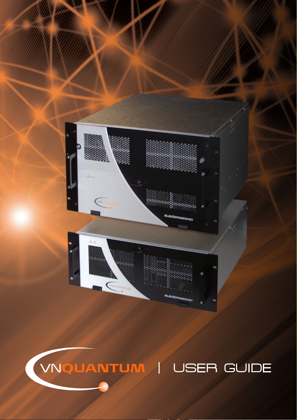
Unpacking Procedure
The VN-QUANTUM Processor, together with various cables and accessories, is shipped in a sturdy
wooden crate.
CAUTION: The crate is extremely heavy and two-person lifting is required.
To unpack the contents...
Remove the eight screws (A) around the
bottom edge of the crate.
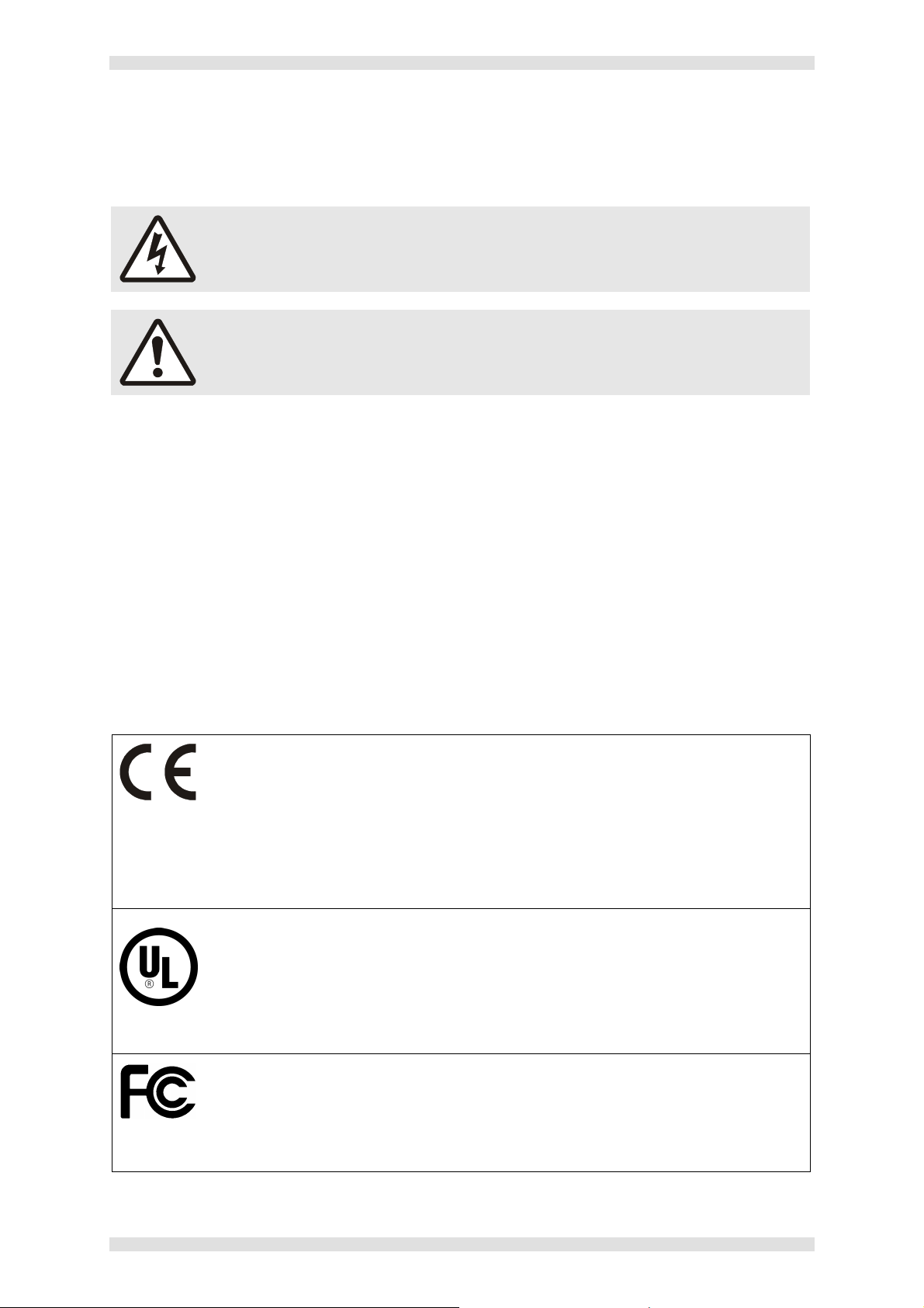
Using the lifting handles, carefully lift the top
half of the crate up and away from the
internal packaging and components.
HINT: You can also remove the eight screws
around the top edge of the crate. This will allow
the top panel to be removed, and the sides to be
folded flat for easy storage. It is recommended
that you retain the crate and all packaging for any
future transportation.
A
A
A
A
Page 10 I455GB issue 8
Page 11
VN-QUANTUM User Guide Section 1: Installation & Setup
Checking the Supplied Components
Before installing or using the VN-QUANTUM processor please check that all of the following items
have been supplied in the shipping crate and have not been damaged during transit
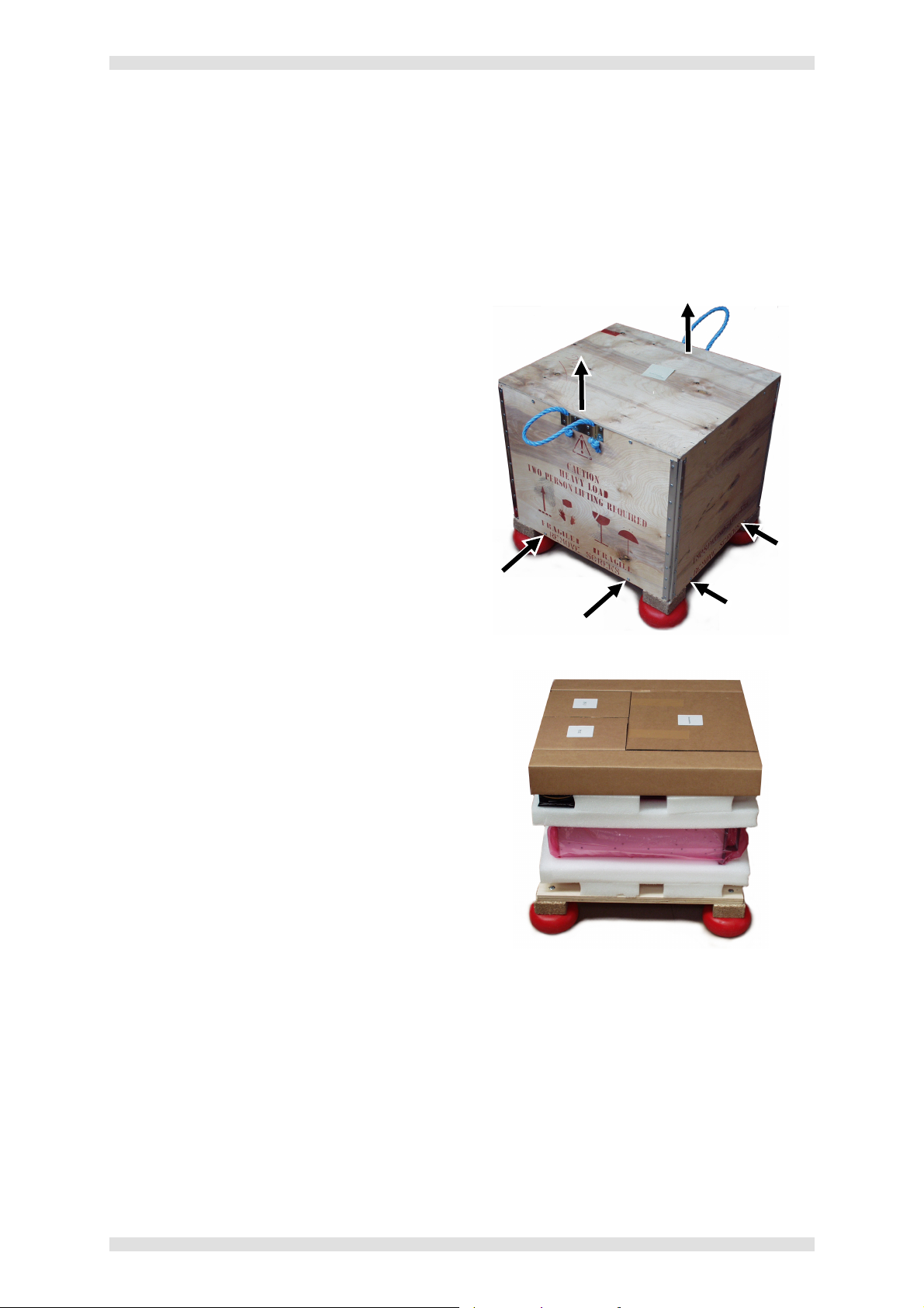
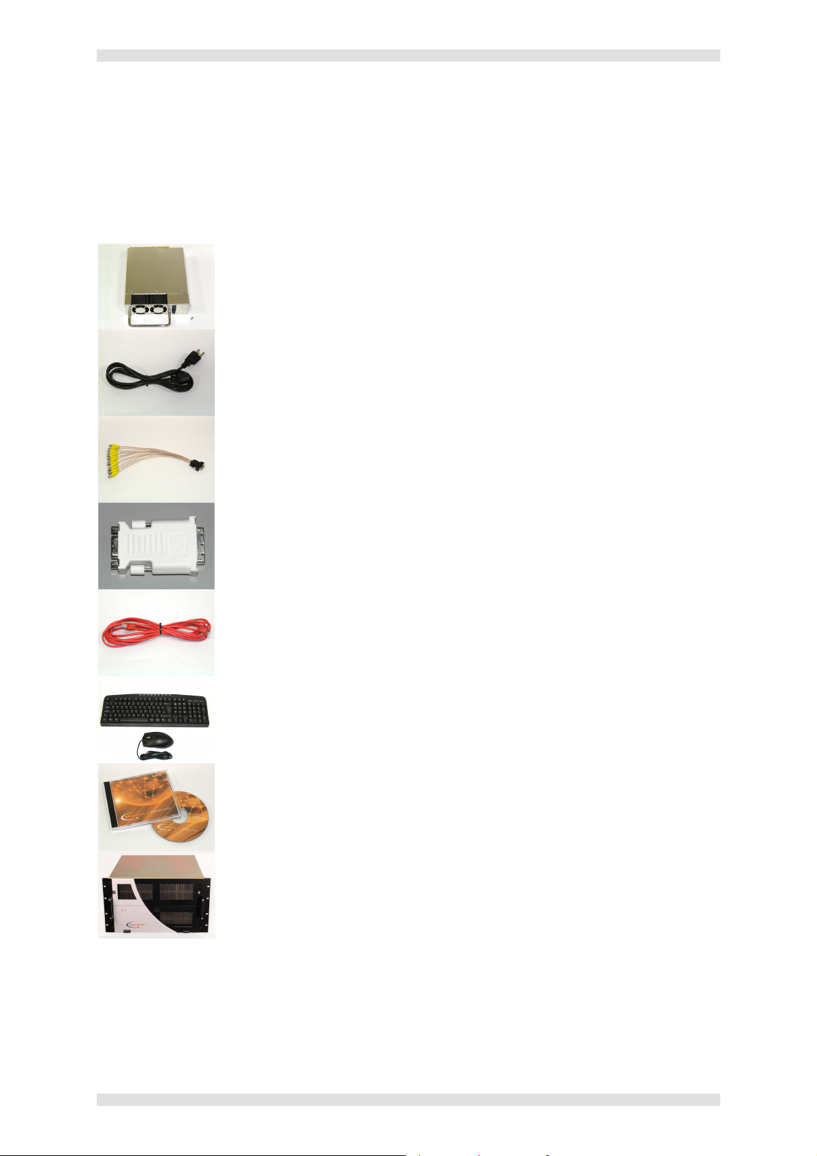
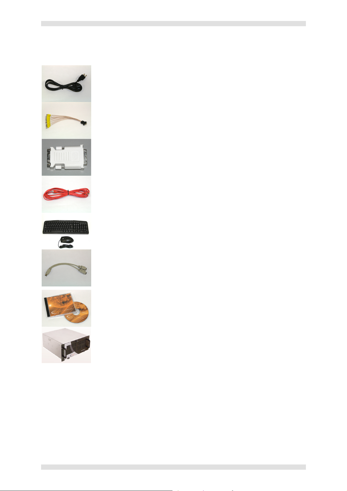
ES3301-2 Check List
Power Supply Units (PSUs)
Two Card Frame PSUs are packed separately for transit and need to be installed
into the Card Frame prior to use. See page 13 for installation details.
Mains Power Cords
Two IEC 320 (C14) mains power cards are supplied. One is terminated in a 3-pin
‘Edison’ plug (for USA) and the other is unterminated (for Europe and elsewhere).
See page 19 for further details on connecting the mains supply.
Input Card Breakout Cables
These are 26-pin D-type connectors with 12 coaxial flying leads, each approx.
400mm in length and terminated in an inline BNC connector. Check that you have
two cables for each Input Card.
DVI-A to 15-pin VGA Adapters
These adapters are used to connect 15-pin VGA style connectors to the DVI output
connectors. Check that you have two adapters for each Output Card.
Network Crossover Cable
A 5 metre (16ft) crossover patch cable, suitable for direct Ethernet connection
between the VN-QUANTUM Card Frame and the VN-COMMANDER Control PC.
Keyboard and Mouse
A PS/2 compatible QWERTY keyboard and mouse used for low level setup of the
VN-QUANTUM processor.
System Disc
A CD-ROM containing VN-QUANTUM software, including VN-COMMANDER, and
User Documentation. Documentation is supplied in Adobe Acrobat (PDF) format.
VN-QUANTUM Card Frame
With Input and Output Cards pre-installed to order. Compact Flash cards are also
pre-installed.
I455GB issue 8 Page 11
Page 12
Section 1: Installation & Setup VN-QUANTUM User Guide
ES3302 & ES3304 Check List
Mains Power Cords
Two IEC 320 (C14) mains power cards are supplied. One is terminated in a 3-pin
‘Edison’ plug (for USA) and the other is unterminated (for Europe and elsewhere).
See page 19 for further details on connecting the mains supply.
Input Card Breakout Cables
These are 26-pin D-type connectors with 12 coaxial flying leads, each approx.
400mm in length and terminated in an inline BNC connector. Check that you have
two cables for each Input Card.
DVI-A to 15-pin VGA Adapters
These adapters are used to connect 15-pin VGA style connectors to the DVI output
connectors. Check that you have two adapters for each Output Card.
Network Crossover Cable
A 5 metre (16ft) crossover patch cable, suitable for direct Ethernet connection
between the VN-QUANTUM Card Frame and the VN-COMMANDER Control PC.
Keyboard and Mouse
A PS/2 compatible QWERTY keyboard and mouse used for low level setup of the
VN-QUANTUM processor.
PS/2 Splitter Cable
A splitter cable for connecting both the keyboard and mouse to the VN-QUANTUM
PS/2 port.
System Disc
A CD-ROM containing VN-QUANTUM software, including VN-COMMANDER, and
User Documentation. Documentation is supplied in Adobe Acrobat (PDF) format.
VN-QUANTUM Card Frame
With Input and Output Cards pre-installed to order.
Page 12 I455GB issue 8
Page 13
VN-QUANTUM User Guide Section 1: Installation & Setup
Retaining
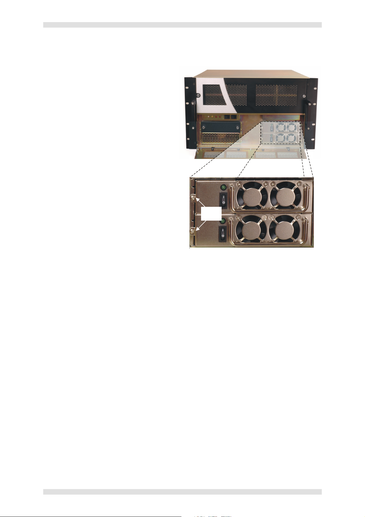
Fitting the Power Supply Units (ES3301-2 only)
Open the lower front access panel of the
Card Frame. (The panel is secured by a
quarter-turn latch).
Remove the retaining screw from the left-
hand side of both PSU compartments.
Insert a PSU fully into each compartment
and secure with the retaining screw.
I455GB issue 8 Page 13
Page 14
Section 1: Installation & Setup VN-QUANTUM User Guide
g
t
o
a
N
e
t
w
o
r
k
g
a
K
e
y
b
o
a
r
d
,
M
o
u
s
e
&
e
t
w
o
r
k
S
e
t
u
p
)
N
e
t
w
o
r
k
2
N
e
t
w
o
r
k
1
(
page
24
)
(
page
22
)
(
page
20
)
(
page
25
)
(
page
12
)
(
page
27
)
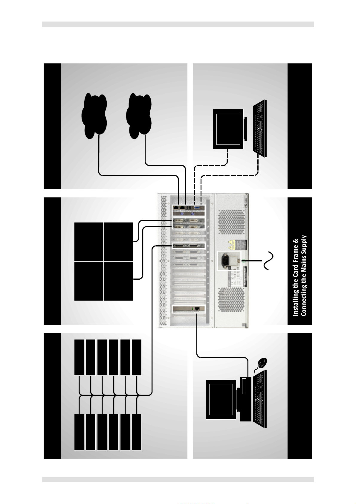
ES3301-2 Installation Overview
Monitor (N
Connectin
Connecting the Display Connectin
Connecting Sources
Page 14 I455GB issue 8
Connecting the Control PC
(VN-COMMANDER)
Page 15
VN-QUANTUM User Guide Section 1: Installation & Setup
g
t
o
a
N
e
t
w
o
r
k
g
a
K
e
y
b
o
a
r
d
,
M
o
u
s
e
&
e
t
w
o
r
k
S
e
t
u
p
)
N
e
t
w
o
r
k
2
N
e
t
w
o
r
k
1
(
page
24
)
(
page
22
)
(
page
20
)
(
page
25
)
(
page
12
)
(
page
27
)
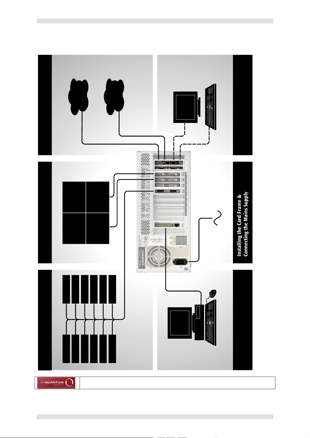
ES3302 & ES3304 Installation Overview
Monitor (N
Connectin
Connecting the Display Connectin
Connecting Video Sources
Note: The ES3304 VN-QUANTUM CONNECT processor does not support the use
of the Media ports (Network interface 1 & 2).
Connecting the Control PC
(VN-COMMANDER)
I455GB issue 8 Page 15
Page 16

Section 1: Installation & Setup VN-QUANTUM User Guide
Installing the Card Frame
Choosing a Suitable Location
The VN-QUANTUM Processor is primarily designed to be mounted in a 19 inch equipment rack.
However, it can be used as a freestanding unit if required.
CAUTION
However you decide to use the VN-QUANTUM Processor there are certain
environmental requirements, detailed on page 17, which must be observed in
order to ensure safe and reliable operation.
For rack-mounted applications the criteria detailed on page 18, must also be
observed.
Lifting and Moving the VN-QUANTUM Processor
The VN-QUANTUM Processor is very heavy. When fully populated with input/output cards:
The ES3301-2 weighs up to up to 27.5kg / 61 lbs
The ES3302 weighs up to up to 17.5kg / 38.6 lbs
It is strongly recommended that you seek assistance when lifting or moving it.
Page 16 I455GB issue 8
Page 17

VN-QUANTUM User Guide Section 1: Installation & Setup
Environmental Requirements
CAUTION
The criteria on this page must be observed for all VN-QUANTUM Processor
installations, whether free-standing or rack-mounted.
Orientation
The VN-QUANTUM Processor must be operated in the horizontal position only. When used freestanding it must be placed on a stable, flat and level surface.
Temperature
DO NOT install or operate the VN-QUANTUM Processor in an area where the ambient temperature
exceeds 35°C (95°F) or falls below 5°C (35°F).
Remember that, as with all electronic equipment, the VN-QUANTUM Processor also produces heat
which will affect the ambient temperature.
Ventilation
DO NOT obstruct the front or rear ventilation grilles during operation as this will restrict the air flow
and may cause the VN-QUANTUM Processor to overheat.
A ventilation gap of at least 100mm must be left between the front and rear panels of the VNQUANTUM Processor and adjacent surfaces or equipment.
Humidity & Water
DO NOT install or operate the VN-QUANTUM Processor in an area in which the ambient relative
humidity exceeds 85% or in an area that is prone to condensation.
DO NOT install or operate the VN-QUANTUM Processor near water or in a location which may be
prone to water — the VN-QUANTUM Processor card frame is not waterproof.
WARNING: To avoid the possible risk of electric shock or product damage due to condensation,
ALWAYS allow the VN-QUANTUM Processor to become acclimatized to ambient temperature and
humidity for at least thirty minutes BEFORE switching on. This is particularly important when moving
the unit from a cold to a warm location.
I455GB issue 8 Page 17
Page 18

Section 1: Installation & Setup VN-QUANTUM User Guide
Rack-mount Requirements
CAUTION
For rack-mounted installations, the following criteria must be observed (in
addition to the Environmental Requirements listed on page 17).
Mounting & Support
ALWAYS use additional support at the sides or rear of the VN-QUANTUM card frame. For example,
by installing a suitable rack-mountable shelf beneath the unit, fixed to both the front and rear rack
posts. Ensure that the shelf (or other mounting accessories) can support the full weight of the unit:
The ES3301-2 weighs up to 27.5kg / 61 lbs (when fully populated)
The ES3302 & ES3304 weighs up to 17.5kg / 38.6 lbs (when fully populated)
NEVER rely on the integral rack-mount brackets to support the full weight of the unit. These must only
be used to secure the unit within the rack.
DO NOT stand other units directly on top of the VN-QUANTUM Processor when it is rack-mounted as
this may overload the mountings.
Ventilation
ALWAYS ensure that the rack enclosure is adequately ventilated. Sufficient airflow must be achieved
(by convection or forced-air cooling) to satisfy the ventilation requirements of all items of equipment
installed within the rack.
A ventilation gap of at least 100mm must be left between the front and rear panels of the VNQUANTUM Processor and adjacent surfaces or equipment.
No ventilation space is necessary above or below the VN-QUANTUM Processor.
Mains Supply
ALWAYS ensure that the mains power supply is of the correct voltage and frequency for all
equipment within the rack, and that it has a good ground/earth connection.
Where a power strip (mains distribution batten) is used (of either a hard-wired or plug and socket
type), always ensure that the current rating of both the power strip and the supply is sufficient for all
equipment within the rack. Refer to the equipment rating plates or user documentation to establish
power requirements.
Page 18 I455GB issue 8
Page 19

VN-QUANTUM User Guide Section 1: Installation & Setup
Connecting the Mains Supply
Supply Requirements
ALWAYS observe the following instructions to ensure safe and reliable
operation of the VN-QUANTUM Processor:
WARNING: THIS EQUIPMENT MUST BE GROUNDED / EARTHED.
NEVER connect the VN-QUANTUM Processor to a power point that does not have a ground or earth
connection.
ALWAYS ensure that the mains supply voltage is single phase only and is within the permitted range:
110V / 230V AC (13A / 6 A Max.) 50 – 60Hz.
NEVER connect this product to a D.C. supply.
DO NOT allow the mains power point to be overloaded. This is particularly important to check when
powering several items of equipment from a single power point (e.g. within rack-mounted
installations). Refer to the equipment rating plates or user documentation to establish power
requirements.
WARNING: To avoid the possible risk of electric shock or product damage due to condensation,
ALWAYS allow the VN-QUANTUM Processor to become acclimatized to ambient temperature and
humidity for at least thirty minutes BEFORE switching on. This is particularly important when moving
the unit from a cold to a warm location.
IMPORTANT: VN-QUANTUM features a ‘soft’ power switch. External power isolation must, therefore,
be provided within easy reach of the unit. For example, mains connection must be via a switched
power socket or power isolator located near to, and easily accessible from, the VN-QUANTUM card
frame.
I455GB issue 8 Page 19
Page 20
Section 1: Installation & Setup VN-QUANTUM User Guide
Mains Power Cord
The VN-QUANTUM Processor is equipped with an IEC320 C14 3-pin (male) type mains connector
which requires a power cord fitted with an IEC320 C13 (female) connector.
Two power cords are supplied with the VN-QUANTUM Processor, each having a different termination;
you must use the lead appropriate for the country of installation:
In... Use the... Re-order Code
USA and Canada
UK, Europe and all
other countries
WARNING: Do not allow anything to rest on the mains power cord.
cord fitted with the 3-pin
American-style ‘Edison’ plug.
unterminated cord and fit a
suitable plug as described on
page 21.
CA4292
CA429
Page 20 I455GB issue 8
Page 21
VN-QUANTUM User Guide Section 1: Installation & Setup
Fitting a Mains Plug
If you are fitting a plug to the unterminated power cord (or replacing an existing plug),
the plug MUST:
• be rated for use with mains voltage
• be equipped with a grounding pin/connection
• comply with any applicable National or Local electrical regulations.
• be fitted with a correctly rated fuse (applicable to UK-style plugs only – see page 22.)
WARNING: Never attempt to fit or use a plug without a grounding or earthing pin/connection.
Wiring Details
The wires of both mains power cords (supplied with each VN-QUANTUM Processor) are color-coded
as shown in the table below; be sure to connect your plug in accordance with the
following guidelines:
Connect the wire
colored...
Brown
to the plug terminal identified
with...
‘L’ or ‘Live’ or ‘Line’
(or colored red or brown)
Blue
‘N’ or ‘Neutral’
(or colored blue or black)
Green & Yellow
‘ ’ or ‘E’ or ‘Earth’ or ‘Ground’
(or colored green or green & yellow)
WARNING — If you are unsure of the connections,
or if the markings in your plug do not match those
given above,
CONSULT A QUALIFIED ELECTRICIAN.
WARNING: THIS EQUIPMENT MUST BE GROUNDED / EARTHED.
I455GB issue 8 Page 21
Page 22
Section 1: Installation & Setup VN-QUANTUM User Guide
External Supply Protection
The mains power cord must be protected from overload by an external fuse or
circuit breaker.
Fused Plugs (UK-style)
If the power cord is fitted with a UK-style BS1363 3-pin plug (i.e. with provision for an internal fuse),
then it must be fitted with a BS1362 ASTA approved 1 inch cartridge fuse rated at 10A/250V.
Unfused Plugs or Hard-wired Installation
If the power cord is fitted with an unfused plug, or is hard-wired into a power strip (mains distribution
batten), then the power cord must be protected by an external fuse or circuit breaker of a rating
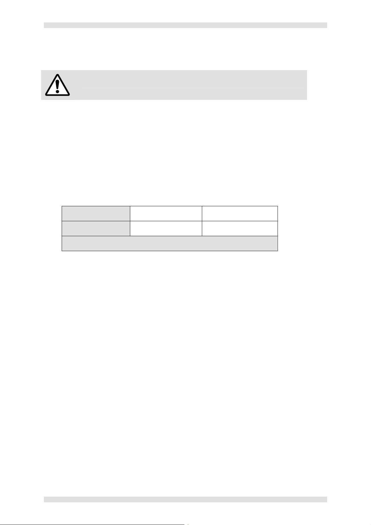
shown in the table below:
Supply Voltage 110V nominal 230V nominal
Fuse Rating 13A 10A
WARNING: Never attempt to fit a fuse or circuit breaker of a higher rating.
Page 22 I455GB issue 8
Page 23

VN-QUANTUM User Guide Section 1: Installation & Setup
Power-up Test (ES3301-2 only)
Ensure that the Card Frame is connected to the mains supply.
Ensure that all ventilation grilles are free from obstruction.
Open the lower front access panel (secured by a quarter-turn latch).
Move both PSU switches to the ON (1) position.
Move the main POWER switch to the ON (1) position.
Check for the following:
o The main POWER indicator lights green.
o Both PSU indicators light green.
o All cooling fans are running.
Briefly turn OFF (0) one of the PSU switches and check that:
o An alarm sounds;
o The main POWER indicator lights red.
Turn the PSU back ON again and check that:
o The alarm stops;
o The main POWER indicator lights green.
Close the lower front access panel and secure with the latch.
I455GB issue 8 Page 23
Page 24

Section 1: Installation & Setup VN-QUANTUM User Guide
Connecting Sources
Video Sources
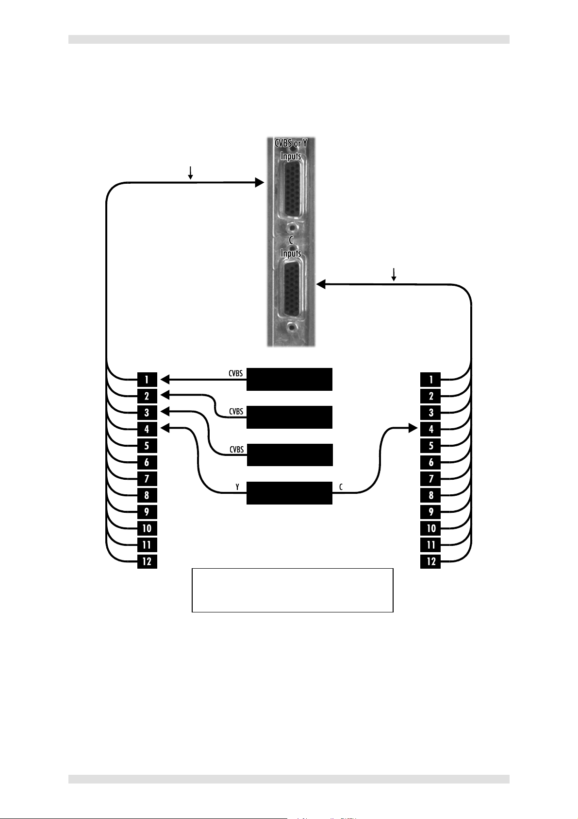
Analog video sources are connected to the Card Frame via one or more ES3311-2 Input Cards. Each
card can accept up to 12 composite (CVBS) or S-Video (YC) sources, and inputs are made via two
multi-way connectors at the rear of each card:
The upper connector is for composite or S-Video luma (Y);
The lower connector is for S-Video chroma (C) only.
Breakout cables are supplied which split the multiway connector into 12 inline BNC sockets. Each
flying lead of the Breakout Cable is numbered from 1 to 12, corresponding to the 12 inputs.
Input Channel Identification
The VN-COMMANDER control software identifies each source by the slot number of the Input Card
and the card input number. For example, sources connected to a card in slot 6 will be identified as
6.1, 6.2, 6.3 and so on up to 6.12.
Page 24 I455GB issue 8
Page 25
VN-QUANTUM User Guide Section 1: Installation & Setup
ES3311-2
S-VHS PLAYER
VIDEO SERVER
ES3311-CA Breakout Cable
ES3311-CA Breakout Cable
(required for S-Video sources only)
NOTE
Connection Example
Card
DVD PLAYER
CAMERA
: The Y and C outputs of an S-Video
source must be connected to the same
input number on both cables.
I455GB issue 8 Page 25
Page 26

Section 1: Installation & Setup VN-QUANTUM User Guide
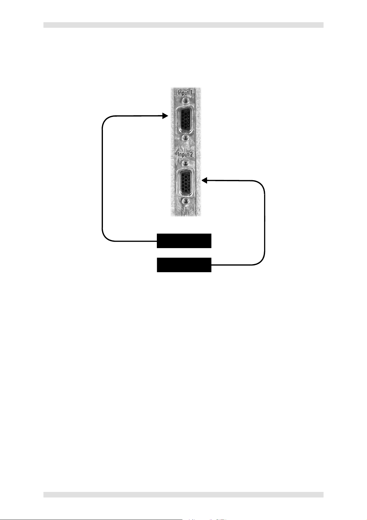
RGB Graphics & HD Video Sources
Analog RGB graphics sources or HD Video sources (in RGB or component YPrPb format) are
connected to the Card Frame via one or more ES3312 RGB Input Cards. Each ES3312 card can
accept 1 or 2 sources, and inputs are made via two standard 15-pin VGA type connectors at the rear
of each card:
The upper connector is for Input 1;
The lower connector is for Input 2.
HINT: Analog RGB graphics sources can also be delivered to VN-QUANTUM over an IP network
connection, by using VN-GLIMPSE. See page 67 for further details.
Input Channel Identification
The VN-COMMANDER control software identifies each source by the slot number of the Input Card
and the card input number. For example, sources connected to a card in slot 5 will be identified as 5.1
and 5.2.
Page 26 I455GB issue 8
Page 27
VN-QUANTUM User Guide Section 1: Installation & Setup
ES3312
RGB / YPrPb Source
RGB / YPrPb Source
Connection Example
Card
I455GB issue 8 Page 27
Page 28

Section 1: Installation & Setup VN-QUANTUM User Guide
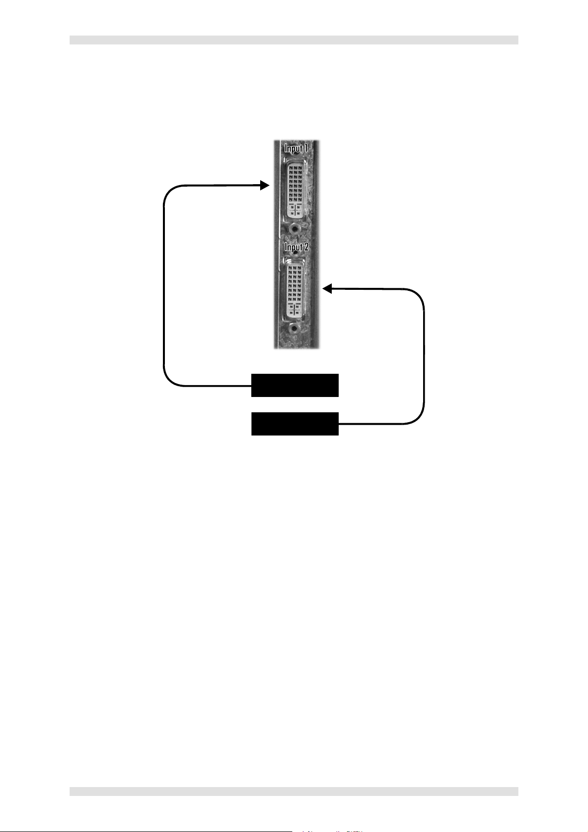
DVI Sources
Digital video or graphics sources are connected to the Card Frame via one or more ES3314 DVI Input
Cards. Each ES3314 card can accept 1 or 2 sources, and inputs are made via two standard DVI-D
type connectors at the rear of each card:
The upper connector is for Input 1;
The lower connector is for Input 2.
Input Channel Identification
The VN-COMMANDER control software identifies each source by the slot number of the Input Card
and the card input number. For example, sources connected to a card in slot 5 will be identified as 5.1
and 5.2.
Page 28 I455GB issue 8
Page 29
VN-QUANTUM User Guide Section 1: Installation & Setup
ES3314
DVI Source
DVI Source
Connection Example
Card
I455GB issue 8 Page 29
Page 30
Section 1: Installation & Setup VN-QUANTUM User Guide
Ch
8.1
8.2
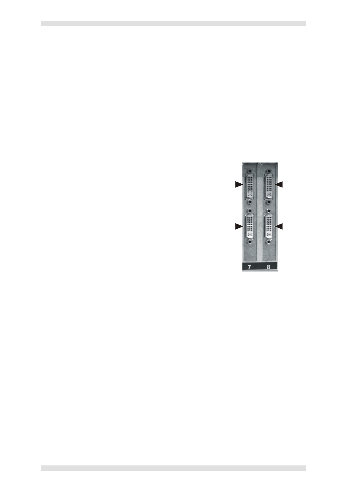
Connecting the Display
Display devices are connected to the Card Frame via one or more ES3310 Output Cards. Each
ES3310 card has two output channels and these are accessed via two DVD-I connectors at the rear
of each card:
The upper connector is for output channel 1;
The lower connector is for output channel 2.
The outputs can be configured (using VN-COMMANDER) to drive either analog or digital devices and
at a variety of resolutions.
When connecting an analog display, you can either use a DVI-A type connector/cable, or use the DVIVGA adapter supplied to allow connection of a conventional 15-pin style VGA cable.
Output Channel Identification
The VN-COMMANDER control software identifies each
output channel by the slot number of the Output Card
and the card channel number.
For example, if you have two Output Cards in slots
7 and 8, the output channels will be identified as
7.1, 7.2, 8.1 and 8.2.
Ch
Ch
7.1
7.2
Ch
Output Channel Mapping
When connecting multi-screen displays, you need to consider the order in which screens are
connected to the various output channels.
You can use VN-COMMANDER to map any Output Card to any location on the target display.
However, there are three ways to use the output channels of each card and the method you choose
will govern how you connect each screen:
Dual channel horizontal; the channels are used to drive two screens placed side by side
Dual channel vertical; the channels are used to drive two screens placed one above the
other
Single channel; only channel 1 is used and channel 2 is left unconnected. This method is
used when the maximum number of windows need to be displayed on a single screen, or if
there are an odd number of screens in the display.
You should choose whichever method (or combination of methods) best suits the layout of the target
display, using the examples on the next page as a guide.
Refer to the VN-COMMANDER (Quantum Edition) User Guide for details of how to map the outputs to
your target display.
Page 30 I455GB issue 8
Page 31

VN-QUANTUM User Guide Section 1: Installation & Setup
8.1
7.1
4.1
4.1
4.1
6.1
3.1
8.2
7.2
5.1
5.1
4.2
7.1
3.2
7.1
7.1
6.1
5.1
8.1
4.1
8.1
8.1
4.2
8.1
6.1
4.2
6.1
6.2
5.1
8.2
7.1
5.2
8.1
7.2
5.2
7.2
6.2
5.2
8.2
6.1
8.2
6.2
7.1
6.2
7.1
7.2
7.1
7.2
8.1
7.2
8.1
8.2
Dual Channel Horizontal Configurations
Dual Channel Vertical Configurations
Connection / Mapping Examples
All of the following display layout examples show channel numbering as seen from the normal viewing
position. The first digit is the slot number of the card and the second is the output number. Note that
the actual slot numbers may vary between systems, but the general recommendation is to start with
the lowest numbered card slot in the top left corner.
ES3301-2 Card Frame
ES3302 & 3304 Card Frame
Single Channel Configurations Mixed Configurations
I455GB issue 8 Page 31
Page 32

Section 1: Installation & Setup VN-QUANTUM User Guide
Connecting to a Network
The VN-QUANTUM Card Frame has two separate network ports – MEDIA I and MEDIA II. These
allow connection to external Ethernet Local Area Networks (LAN) or Wide Area Networks (WAN) in
order to access remote VN-GLIMPSE RGB sources or network-based files/media.
If your system does not use VN-GLIMPSE sources or network-based content, these ports can be left
unconnected. Otherwise, you can use either or both ports as required.
Connection between the port(s) and the local network node must be made using a suitable CAT5 STP
patch cable (not supplied).
Network Settings
The VN-QUANTUM is shipped with both ports set to DHCP (Dynamic Hosting Control Protocol),
i.e. an IP Address is automatically assigned by the network.
If the network does not support DHCP you will need to configure the port(s) for fixed IP
communications. Network settings can be changed by connecting a keyboard, mouse and monitor to
the Card Frame. See pages 33 & 36 for further details.
Page 32 I455GB issue 8
Page 33

VN-QUANTUM User Guide Section 1: Installation & Setup
Connecting a Keyboard, Mouse & Monitor
It is only necessary to connect a keyboard, mouse and monitor to the VN-QUANTUM if you need to
perform one of the following operations:
Change Network Settings
Return to Default System Settings
Access Service Mode
Install New Software
VN-QUANTUM only supports PS/2-compatible mice and keyboards. A suitable PS/2 mouse and
keyboard is supplied, together with a splitter cable.
The monitor output is suitable for analog monitors only. A monitor is not provided.
I455GB issue 8 Page 33
Page 34

Section 1: Installation & Setup VN-QUANTUM User Guide
M
E
D
I
A
I
I
M
E
D
I
A
I
Connection Example (ES3301-2 Card Frame)
Page 34 I455GB issue 8
Page 35

VN-QUANTUM User Guide Section 1: Installation & Setup
PS/2 Splitter Cable
Connection Example (ES3302 & 3304 Card Frame)
I455GB issue 8 Page 35
Page 36

Section 1: Installation & Setup VN-QUANTUM User Guide
MEDIA II
MEDIA I
MEDIA II
ES3301-2
MEDIA I
Changing Network Settings (using the VN-QUANTUM Control Panel)
Ensure that the VN-QUANTUM is powered down.
Connect a keyboard, mouse and monitor to the VN-QUANTUM Card Frame (see page 33)
Power-up the VN-QUANTUM processor and wait for the VN-QUANTUM logo to appear on the
monitor (this will take up to 90 seconds).
Press the Ctrl and F2 keys simultaneously to display the VN-QUANTUM Control Panel:
CONTROL
Click on Network Settings to display the
following dialog:
ES3302
CONTROL
In the Network Connection area, choose the
port that you want to change:
o Control (CONTROL connector)
o Media 1 (MEDIA I connector)
o Media 2 (MEDIA II connector)
Change the Network Settings as required
then click Apply or OK.
The new settings will only take effect once the processor has been rebooted.
A message will appear asking you if you want to reboot now.
Click Yes to reboot now or No to reboot later.
Note that the VN-QUANTUM CONNECT processor does not support the use of
the MEDIA I and II ports.
Page 36 I455GB issue 8
Page 37

VN-QUANTUM User Guide Section 1: Installation & Setup
Connecting the Control PC
VN-QUANTUM has a dedicated CONTROL port for the connection of a PC or laptop, running VNCOMMANDER application software.
Connection between the CONTROL port and the PC or laptop must be made using a CAT5 crossover
patch cable (a 5m/16ft cable is supplied).
Control Port Settings
The VN-QUANTUM is shipped with the CONTROL port set to the following:
IP Address 172.28.232.11
Subnet Mask 255.255.000.000
Default Gateway 0.0.0.0
DNS Server 0.0.0.0
WINS Server 0.0.0.0
Name VNQuantum
NOTE: The CONTROL port does not support DHCP operation.
To enable communications between the computer and VN-QUANTUM you must ensure that the IP
Address and Subnet Mask settings are compatible on both devices:
The Subnet Mask for both devices must be the same.
The IP Address must be different, but in the same class/subnet.
To change the settings the VN-QUANTUM CONTROL port, follow the procedure on page 36.
For further help on IP Addressing, see Appendix A.
I455GB issue 8 Page 37
Page 38

Section 1: Installation & Setup VN-QUANTUM User Guide
Installing VN-COMMANDER Software
IMPORTANT NOTE: VN-QUANTUM requires VN-COMMANDER v1.4 software. No other version
of VN-COMMANDER or CT-COMMANDER will work with VN-QUANTUM.
The VN-QUANTUM CONNECT processor requires VN-COMMANDER
CONNECT control software. No other version of VN-COMMANDER will work
with the VN-QUANTUM CONNECT processor.
Computer Specification
The VN-COMMANDER application software must be installed on a computer that meets or exceeds
the following specification:
Minimum Recommended
Operating System
Processor Speed
Memory (RAM)
Hard Disk Free Space
Graphics
Network Card (Ethernet)
Windows NT4 (SP6) Windows 2000, XP
200MHz 450MHz or higher
64MB 128MB or higher
30MB >30MB
1024x768, 65K colors (16-bit) 1024x768, 16.7M colors (32-bit)
10BASE-T 100BASE-T
Installation Procedure
The VN-COMMANDER application software is provided on the VN-QUANTUM System Disc.
Insert the VN-QUANTUM System Disc into a CD-ROM drive on the computer. After a few
seconds the disc browser should start automatically.
HINT: If the disc browser does not start for any reason, start it manually by running the setup.exe
file located on the root of the disc.
Click on the Install VN-COMMANDER option then follow the on-screen instructions.
Page 38 I455GB issue 8
Page 39

VN-QUANTUM User Guide Section 2: Hardware Overview
SECTION 2:
Hardware Overview
I455GB issue 8 Page 39
Page 40

Section 2: Hardware Overview VN-QUANTUM User Guide
Introduction
This section contains a general description of the VN-QUANTUM hardware and concentrates on
giving details of the various hardware components and the location of key physical features. For an
overview of VN-QUANTUM functionality, refer to Section 3.
Note: The ES3304 VN-QUANTUM CONNECT processor has the same
architecture as the ES3302 VN-QUANTUM processor.
Note that the VN-QUANTUM CONNECT has a reduced feature set when
compared to the ES3302 processor:
- No support for GLIMPSE source types.
The VN-QUANTUM is a fully modular system, allowing each unit to be individually configured to best
suit the requirements of the end user application. The hardware comprises a Card Frame into which is
installed a number of Input and Output Cards. The cards, all operating system software and drivers
are pre-installed to order enabling quick and easy installation on site.
The following diagrams show the main hardware components of the VN-QUANTUM Processor:
- No support for picture & image file source types.
- No support for window borders or window text.
- No support for Clock and timer source types.
- No support for multiple processor systems.
- No support for overlapped or over-scanned displays.
- No support for screen capture.
Page 40 I455GB issue 8
Page 41

VN-QUANTUM User Guide Section 2: Hardware Overview
DISPLAY
DEVICES
SCALER
SINGLE BOARD
CPU / Operating System
PCI BUS
CONTROL
RGB SOURCES
(VN-GLIMPSE)
KEYBOARD / MOUSE CONTROL
(for low-level setup only)
ES3310
Output Card(s)
RAPT BUS
Hardware Block Diagram (ES3301-2 Card Frame)
VIDEO
SOURCES
RGB
SOURCES
DVI
SOURCES
Input Card(s)
NETWORK
INTERFACE
1
MEDIA
NETWORK
ES3312
ES3314 ES3301-2
Card
Frame
NETWORK
INTERFACE
2
DATA
NETWORK
COMPUTER
FLASH
MEMORY
DRIVE
NETWORK
INTERFACE
3
PC
NETWORK
CONTENT
I455GB issue 8 Page 41
Page 42

Section 2: Hardware Overview VN-QUANTUM User Guide
DISPLAY
DEVICES
SCALER
SINGLE BOARD
CPU / Operating System
PCI BUS
CONTROL
RGB SOURCES
(VN-GLIMPSE)
KEYBOARD / MOUSE CONTROL
(for low-level setup only)
RAPT BUS
ES3310
Output Card(s)
Hardware Block Diagram (ES3302 & 3304 Card Frame)
VIDEO
SOURCES
RGB
SOURCES
DVI
SOURCES
Input Card(s)
NETWORK
INTERFACE
1
MEDIA
NETWORK
ES3312
ES3314
NETWORK
INTERFACE
2
DATA
NETWORK
ES3302
Card
Frame
COMPUTER
IDE
DISK DRIVE
NETWORK
INTERFACE
3
Page 42 I455GB issue 8
PC
NETWORK
CONTENT
Note: The ES3304 VN-QUANTUM CONNECT processor does not support the use
of the Media ports (Network interface 1 & 2).
Page 43

VN-QUANTUM User Guide Section 2: Hardware Overview
Latch for Lower Access Panel
Status Indicators
Thumb Screws for Upper Access Pa
nel
Button
Button
Drive
15-slot Card Frame (ES3301-2)
Front Panel Features
Cooling Fans
I455GB issue 8 Page 43
Flash
Power On/Off
HINT: For full technical details on the Card Frame see page 91.
O/S Reset
Power Supply
Page 44

Section 2: Hardware Overview VN-QUANTUM User Guide
P
OWER
green
DATA
Status Indicators
: Lit
mains power supply is OK.
Lit red if one of the PSUs has
failed.
when the
: Flashes when data
is being written to, or read
from, the flash drive.
Lower Access Panel & Latch
A fold-down access panel providing access to the following components:
• Power On/Off Button
• System Reset Button
• Flash Drive Bay
• Power Supply Units
The access panel is normally secured in the closed position by a quarter-turn latch.
Power On/Off Button
A rocker switch used to turn the Card Frame power on and off.
O/S Reset Button
A momentary-action rocker switch used to reset the operating system only. It does not force a
reboot of the Input/Output cards. A full system reboot (e.g. as required after installing new firmware)
will require a power reset (i.e. power off, power on).
Flash Drive
A dual-slot compact flash drive:
Top Slot: Used for Operating System and
Hardware Drivers;
Bottom Slot: Used for System Configuration
Data. This card can also be used to store
local source content (e.g. an image file
containing a background for the target
display).
The drive is normally concealed by a removable
cover that is secured by two thumbscrews.
To remove a card, press the button on the righthand side of the card. To insert a card, simply push
the card fully into the slot.
IMPORTANT NOTE: Cards must not be removed
or inserted while the system is operational.
Page 44 I455GB issue 8
Page 45

VN-QUANTUM User Guide Section 2: Hardware Overview
Power Supply Units (PSU)
The Card Frame is fitted with two separate PSUs which operate in a redundant PSU configuration.
Both PSUs must be fitted and powered ON at all times during normal operation. Should either of the
PSUs fail an alarm will sound and the POWER indicator on the front panel will turn red. Both PSUs
must be installed and powered at all times.
CAUTION: In the event of a PSU failure, replace the faulty unit as soon as possible (see page 87).
Upper Access Panel
The top half of the Card Frame front panel is secured by two thumbscrews. Removing this panel gives
access to the cooling fans.
Cooling Fans
Four integral fans provide forced-air ventilation, drawing air in through the front panel and exhausting
via the rear panel. In the event of a fan failure a replacement fan can be easily hot-swapped via the
front panel (see page 88).
CAUTION: In the event of a fan failure, replace the faulty fan as soon as possible to avoid possible
overheating.
I455GB issue 8 Page 45
Page 46

Section 2: Hardware Overview VN-QUANTUM User Guide
Internal Components
CPU / Operating System
System control is achieved by a single board computer (SBC) running an embedded version of
Windows XP with RTX real time extension. This, coupled with the solid-state Flash storage of system
data, ensures maximum integrity and reliability of the operating system.
PCI Bus
A standard high-speed PCI bus provides interconnection between all cards. This primarily carries
control data, plus local/network source data.
RAPT Image Bus
RAPT (Real-time Asymmetric Packetized Transfer) is a high-speed data bus used exclusively for the
transfer of video and RGB Graphics (VN-GLIMPSE) source data between Input and Output Cards.
Unlike PCI technology, RAPT is guaranteed to deliver data in real-time and to remain operational
even in the unlikely event of an operating system crash, allowing crucial source content to be
maintained on the target display.
Page 46 I455GB issue 8
Page 47

VN-QUANTUM User Guide Section 2: Hardware Overview
ES3
311-2 12-Channel Video Input Card
s ES3310 2-
Channel Output
Card
s
Mains Inlet Connector & Latch
PS/2 Ports
Network
Ports
Rear Panel Features
Card Slot 1
Card Slot 15
USB Ports
Control Port
Card Slot 0
(Keyboard/Mouse)
Monitor Out
Mains Inlet Connector & Latch
Mains connection to the unit is via this standard IEC 3-pin connector. A latch is provided which hooks
over the mains plug to prevent it from becoming accidentally loosened or disconnected.
Network Ports
Two separate Gigabit Ethernet (1000Base-T) ports (labeled MEDIA I and MEDIA II) provided for
connection to external local area or wide area networks (LAN or WAN). VN-QUANTUM accesses VNGLIMPSE sources or network based content via these ports.
Control Port
A single Fast Ethernet (100Base-T) port (labeled CONTROL) for connection to an external control
computer, running VN-COMMANDER application software. VN-COMMANDER is used to control the
placement of sources on the target display.
I455GB issue 8 Page 47
Page 48

Section 2: Hardware Overview VN-QUANTUM User Guide
Monitor Output
A connector for an optional VGA-compatible display device (e.g. a CRT or LCD monitor). This can be
used to view internal settings during basic setup, servicing and fault diagnosis procedures. It is not
required during normal operation.
PS/2 Ports
Connectors for an optional PS/2-compatible keyboard and/or mouse. These are required for basic
system setup and troubleshooting only. Not otherwise required for normal operation.
USB Ports
Can be used to connect additional data storage devices, containing images files or software
upgrades. Not otherwise required for normal operation.
Page 48 I455GB issue 8
Page 49

VN-QUANTUM User Guide Section 2: Hardware Overview
Latch for Access Panel
Status Indicators
Button
Button
8-slot Card Frame
Front Panel (ES3302)
HINT: For full technical details on the Card Frame see page 911.
Cooling Fans Removable Hard Disk
O/S Reset
Power On/Off
I455GB issue 8 Page 49
Page 50

Section 2: Hardware Overview VN-QUANTUM User Guide
P
OWER
green
DATA
Front Panel (ES3304 QUANTUM CONNECT)
The ES3304 VN-QUANTUM CONNECT frame has the same physical construction as the ES3302
with a different front panels design.
Front Panel Features
Status Indicators
: Lit
mains power supply is OK.
Lower Access Panel & Latch
A fold-down access panel providing access to the following components:
• Power On/Off Button
• System Reset Button
• Removable Hard Disk Drive
The access panel is normally secured in the closed position by a quarter-turn latch.
when the
: Flashes when data
is being written to, or read
from, the hard disk drive.
Power On/Off Button
A rocker switch used to turn the Card Frame power on and off.
O/S Reset Button
A momentary-action rocker switch used to reset the operating system only. It does not force a
reboot of the Input/Output cards. A full system reboot (e.g. as required after installing new firmware)
will require a power reset (i.e. power off, power on).
Removable Hard Disk Drive
A 40GB IDE hard disk drive in a removable caddy. The caddy is normally locked in position by a key
(supplied). The drive is partitioned and used as follows:
Page 50 I455GB issue 8
Page 51

VN-QUANTUM User Guide Section 2: Hardware Overview
C: for the operating system, and
D: for system configuration files and image files.
NOTE: This drive is not hot-swappable.
Cooling Fans
Two integral fans provide forced-air ventilation, drawing air in through the front panel and exhausting
via the rear panel. In the event of a fan failure a replacement fan can be easily hot-swapped via the
front panel (see page 88).
CAUTION: In the event of a fan failure, replace the faulty fan as soon as possible to avoid possible
overheating.
I455GB issue 8 Page 51
Page 52

Section 2: Hardware Overview VN-QUANTUM User Guide
Internal Components
CPU / Operating System
System control is achieved by a single board computer (SBC) running an embedded version of
Windows XP with RTX real time extension.
PCI Bus
A standard high-speed PCI bus provides interconnection between all cards. This primarily carries
control data, plus local/network source data.
RAPT Image Bus
RAPT (Real-time Asymmetric Packetized Transfer) is a high-speed data bus used exclusively for the
transfer of video and RGB Graphics (VN-GLIMPSE) source data between Input and Output Cards.
Unlike PCI technology, RAPT is guaranteed to deliver data in real-time and to remain operational
even in the unlikely event of an operating system crash, allowing crucial source content to be
maintained on the target display.
Page 52 I455GB issue 8
Page 53

VN-QUANTUM User Guide Section 2: Hardware Overview
ES3
311-2 12-Channel Video Input Card
s ES3310 2-
Channel Output
Card
s
Mains Inlet Connector
PS/2 Port
Network
Ports
Rear Panel Features
Card Slot 1
Card Slot 8
Monitor Out
Control Port
USB Ports
(Keyboard/Mouse)
Mains Inlet Connector
Mains connection to the unit is via this standard IEC 3-pin connector.
Network Ports
Two separate Ethernet ports (labeled MEDIA I and MEDIA II) provided for connection to external local
area or wide area networks (LAN or WAN). VN-QUANTUM accesses VN-GLIMPSE sources or
network based content via these ports.
MEDIA I is 100Base-T (Fast Ethernet) and MEDIA II is 1000Base-T (Gigabit Ethernet).
Note: The ES3304 VN-QUANTUM CONNECT processor does not support the use
of the Media ports (Network interface 1 & 2).
Control Port
A single Fast Ethernet (100Base-T) port (labeled CONTROL) for connection to an external control
computer, running VN-COMMANDER application software. VN-COMMANDER is used to control the
placement of sources on the target display.
I455GB issue 8 Page 53
Page 54

Section 2: Hardware Overview VN-QUANTUM User Guide
Monitor Output
A connector for an optional VGA-compatible display device (e.g. a CRT or LCD monitor). This can be
used to view internal settings during basic setup, servicing and fault diagnosis procedures. It is not
required during normal operation.
PS/2 Port
A connector for an optional PS/2-compatible keyboard and/or mouse. These are required for basic
system setup and troubleshooting only. Not otherwise required for normal operation. A splitter cable is
supplied to allow both the keyboard and mouse to be connected to the single socket.
USB Ports
Can be used to connect additional data storage devices, containing images files or software
upgrades. Not otherwise required for normal operation.
Page 54 I455GB issue 8
Page 55

VN-QUANTUM User Guide Section 2: Hardware Overview
Input / Output Cards
12-Channel Video Input Card (ES3311-2)
The ES3311-2 Input Card allows external analog video sources to be digitized and used by the
VN-QUANTUM Processor.
Each card has 12 source inputs which can be used with either composite video or s-video sources.
Full auto-detection is provided on each input, allowing a wide range of standard source types to be
connected without the need for any further configuration.
The maximum number of ES3311-2 cards that can be installed is limited only by the number of
available card slots (see table on page 57). With the minimum of one Output Card fitted:
The ES3301-2 Card Frame can accommodate up to 14 Input Cards,
allowing a maximum of 168* video source inputs.
The ES3302 & 3304 Card Frame can accommodate up to 7 Input Cards,
allowing a maximum of 84* video source inputs.
*The maximum number of video sources that can be displayed simultaneously is determined by
the rectangulation limit of the Output Cards (for further details see page 74).
For full technical details on the ES3311-2 card, see page 99.
2-Channel RGB Input Card (ES3312)
The ES3312 Input Card allows external analog RGB graphics sources or HD Video sources (in RGB
or component YPrPb format) to be digitized and used by the VN-QUANTUM Processor.
Each ES3312 card has 2 source inputs which can be used with either analog RGB or component
YPrPb sources. Full auto-detection is provided on each input, allowing a wide range of standard
source types to be connected without the need for any further configuration.
The maximum number of ES3312 cards that can be installed is limited only by the number of available
card slots (see table on page 57). With the minimum of one Output Card fitted:
The ES3301-2 Card Frame can accommodate up to 14 Input Cards,
allowing a maximum of 28 RGB/HD source inputs.
The ES3302 & 3304 Card Frame can accommodate up to 7 Input Cards,
allowing a maximum of 14 video source inputs.
For full technical details on the ES3312 card, see page 101.
I455GB issue 8 Page 55
Page 56

Section 2: Hardware Overview VN-QUANTUM User Guide
2-Channel DVI Input Card (ES3314)
The ES3314 Input Card allows external digital video or graphics sources to be used by the VNQUANTUM Processor.
Each ES3314 card has 2 source inputs. Full auto-detection is provided on each input, allowing a wide
range of standard source types to be connected without the need for any further configuration.
The maximum number of ES3314 cards that can be installed is limited only by the number of available
card slots (see table on page 57). With the minimum of one Output Card fitted:
The ES3301-2 Card Frame can accommodate up to 14 Input Cards,
allowing a maximum of 28 RGB/HD source inputs.
The ES3302 & 3304 Card Frame can accommodate up to 7 Input Cards,
allowing a maximum of 14 video source inputs.
For full technical details on the ES3314 card, see page 102.
2-Channel Output Card (ES3310)
The ES3310 Output Card provides the final output to a target display. The Card composites all
sources to be displayed into a layout defined by the VN-COMMANDER software.
The ES3310 card has two output channels, each being capable of driving a ‘standalone’ display
device or one screen element in a larger ‘tiled’ display (e.g. a videowall).
The output signal format can be either analog (RGB) or digital (DVI) format, up to UXGA resolution,
and up to 60Hz refresh rate.
The maximum number of ES3310 cards that can be installed is limited only by the number of available
card slots (see table on page 57). With the minimum of one Input Card fitted:
The ES3301-2 Card Frame can accommodate up to 14 Output Cards,
allowing a maximum of 28 display outputs.
The ES3302 & 3304 Card Frame can accommodate up to 7 Output Cards,
allowing a maximum of 14 display outputs.
For full technical details on the ES3310 card, see page 98.
Page 56 I455GB issue 8
Page 57

VN-QUANTUM User Guide Section 2: Hardware Overview
Card Arrangement
VN-QUANTUM Card Frames are configured to order. Therefore, the precise combination and position
of cards will vary from system to system and may not be as illustrated on previous pages.
At least one Output Card and one Input Card will be required in all cases but, other than that, any
number or mix of Input and Output cards may be used depending on the number of input or output
channels required and the number of available slots.
The following tables provide a quick reference for the maximum number of inputs and outputs
available for different card combinations, assuming all slots are used:
ES3301-2 (15 slots)
Output
Cards
1 2 14 168 28
2 4 13 156 26
3 6 12 144 24
4 8 11 132 22
5 10 10 120 20
6 12 9 108 18
7 14 8 96 16
8 16 7 84 14
9 18 6 72 12
10 20 5 60 10
11 22 4 48 8
12 24 3 36 6
13 26 2 24 4
14 28 1 12 2
At least one Input and Output Card must be installed.
A maximum of 64 sources can be viewed simultaneously with 1 output card.
A maximum of 128 sources can be viewed simultaneously with 2 output cards.
G
VN-GLIMPSE sources are transported over IP and do not occupy input card slots.
Output
Channels
Input
Cards
Video Input
Channels
RGB/HD/DVI Input
Channels
ES3302 & ES3304 (8 slots)
Output
Cards
1 2 7 84 14
2 4 6 72 12
3 6 5 60 10
4 8 4 48 8
5 10 3 36 6
6 12 2 24 4
7 14 1 12 2
At least one Input and Output Card must be installed.
A maximum of 64 sources can be viewed simultaneously with 1 output card
G
VN-GLIMPSE sources are transported over IP and do not occupy input card slots.
Output
Channels
Input
Cards
Video Input
Channels
RGB/HD/DVI Input
Channels
In a standard configuration, Output Cards are installed in the slots nearest the Single Board Computer
(SBC), i.e. slot 15 downwards on the ES3301-2 or slot 8 downwards on the ES3302 / 3304. Input
Cards are installed in the remaining slots nearest the Output Cards. This arrangement allows every
output channel to have access to every video input.
I455GB issue 8 Page 57
Page 58

Section 3: Functional Overview VN-QUANTUM User Guide
SECTION 3:
Functional Overview
Page 58 I455GB issue 8
Page 59

VN-QUANTUM User Guide Section 3: Functional Overview
DISPLAY
DISPLAY
DISPLAY
VN-GLIMPSE
RGB ADAPTER
USER
DISPLAY
PC
PC
PC
PC
System Overview
The diagram below shows an example system application for a VN-QUANTUM Display Processor.
In this particular application, a selection of video, RGB and network sources can be displayed on a
4-screen target display. The VN-COMMANDER software application is responsible for controlling the
VN-QUANTUM and placing the required sources onto the target display.
CONTROL NETWORK SOURCES
w
VN-
COMMANDER
t
e
n
-
N
V
NETWORK
V
N
-
G
USER PC
SERVER
or
t
n
e
t
n
o
c
k
r
o
r
u
t
p
a
c
e
r
a
w
t
f
o
s
(
e
c
r
u
o
s
E
S
P
M
I
L
G
L
IMP
S
E
s
our
ce
(ha
r
d
w
a
re
c
a
p
tur
VN-GLIMPSE
SERVER
)
d
e
PC
ed)
control
network
VN-QUANTUM PROCESSOR
video inputs RGB inputs
CAMERA
CAMERA
CAMERA
CAMERA
EXTERNAL SOURCES
Note: The ES3304 VN-QUANTUM CONNECT HDD does not support the use of
the Media ports (Network interface 1 & 2).
display outputs
DEVICE
DEVICE
TARGET DISPLAY
DEVICE
DEVICE
I455GB issue 8 Page 59
Page 60

Section 3: Functional Overview VN-QUANTUM User Guide
External Sources
Analog video sources, such as cameras, VHS/DVD players and video servers, are input into the
VN-QUANTUM Processor through one or more ES3311-2 Input Cards.
Analog RGB graphics or HD Video sources are input into the VN-QUANTUM Processor through one
or more ES3312 Input Cards.
12-Channel Video Input Card (ES3311-2)
Card Architecture
The following diagram shows the main functional blocks of the ES3311-2 card and basic data/signal
flow through the card:
Each ES3311-2 card can accept up to 12 sources of either composite (CVBS) or s-video (YC). The
maximum number of cards that can be installed is limited only by the number of available card slots
(see table on page 57). With the minimum of one Output Card fitted:
The ES3301-2 Card Frame can accommodate up to 14 Input Cards,
allowing a maximum of 168* video source inputs.
The ES3302 / 3304 Card Frame can accommodate up to 7 Input Cards,
allowing a maximum of 84* video source inputs.
*The maximum number of video sources that can be displayed simultaneously is determined by the
rectangulation limit of the Output Cards (for further details see page 74).
For full technical data on the ES3311-2 Input Card, including connector pin-outs, see page 99.
Page 60 I455GB issue 8
Page 61

VN-QUANTUM User Guide Section 3: Functional Overview
Auto-detection of Source Types
Full auto-detection is provided on each input, allowing a wide range of standard source types to be
connected without the need for any further configuration. However, VN-COMMANDER provides the
means to create fixed or custom input modes.
NOTE: PAL 60 format is not supported. PAL 60 is commonly output by European VCRs when playing
back an NTSC tape.
Automatic gain control (AGC) ensures optimum source display with signals as low as 20% of normal
amplitude.
NOTE: Due to the dynamic nature of AGC an identical source fed to different inputs may not display
with identical results.
Timebase Correction (Frame Synchronization)
Incoming sources are digitized and then synchronized internally to a specified clock signal derived
from either:
The refresh rate of the display outputs; or
The refresh rate of a designated video source input.
This ensures clean switching between sources without the need for any external source
synchronization.
NOTE: If frame-accurate synchronization is required between some or all sources, these will need to
be synchronized externally.
Macrovision-encoded Sources
Many pre-recorded videos and DVD’s are copy-protected by a system called Macrovision®. It works
by inserting variable intensity signals into the non-visible region of the source signal. These ‘false’
signals ‘confuse’ the AGC circuit of conventional recording devices, preventing the source from being
copied satisfactorily.
Typically more than 90% of Macrovision-encoded sources can be viewed successfully. However,
certain sources may suffer some visual disturbance or fail to achieve full signal lock.
I455GB issue 8 Page 61
Page 62

Section 3: Functional Overview VN-QUANTUM User Guide
De-interlacing
VN-QUANTUM outputs a progressive scan to the target display. Most sources that will be connected
to the Video Input Card will be interlaced scan and need to be converted to a progressive scan (or
‘de-interlaced’. The Video Input Card can use one of two de-interlacing modes:
Single Field Interpolation
Three Field Interpolation
For a full explanation of these modes please see page 76.
Down-Scaling of Video Sources
The on-board scaler provides down-scaling (minification) of video sources. Independent horizontal
and vertical scaling is possible down to 1/16 of native resolution. For example, a source of 720x486
pixels can be scaled down to around 45x31 pixels.
More than one scaled version of each source is possible, subject to the maximum number of sources
supported by the scaler:
Source Type De-interlacing
(PAL/NTSC/SECAM)
Single field 30 64 Video
Three field 15 64
* Also dependant on the source capacity of the RAPT bus.
The scaling engine is built around Electrosonic’s patented convolver technology. This ensures that
original image detail and quality is maintained at all times.
Up-scaling (magnification) is achieved by a scaler on the Output Card. See page 75 for
further details on source scaling.
Maximum number of
Sources Supported (per card)*
Real-time Absolute
Source Transfer
Digitized video sources are transferred on to the RAPT bus for transport to the Output Card(s).
NOTE: VN-GLIMPSE RGB sources use a DMA (Direct Memory Access) process on an ES3311-2
Input Card to transfer source data to the RAPT bus.
Only sources that are currently visible on the target display are transferred to the bus.
Page 62 I455GB issue 8
Page 63

VN-QUANTUM User Guide Section 3: Functional Overview
RGB Input Card
2
R
G
B
/
Y
P
r
P
b
I
n
p
u
t
s
PCI BUS
RAPT BUS
2-Channel RGB Input Card (ES3312)
Card Architecture
The following diagram shows the main functional blocks of the ES3312 card and basic data/signal
flow through the card:
ES3312
RGB
DECODER
PROCESSING & DOWN-SCALING
CONTROL
Each card can accept 1 or 2 analog RGB graphics sources or HD Video sources (in RGB or
component YPrPb format). The maximum number of ES3312 cards that can be installed is limited
only by the number of available card slots (see table on page 57). With the minimum of one Output
Card fitted:
The ES3301-2 Card Frame can accommodate up to 14 Input Cards,
allowing a maximum of 28 RGB/HD source inputs.
The ES3302 & 3304 Card Frame can accommodate up to 7 Input Cards,
allowing a maximum of 14 RGB/HD source inputs.
For full technical data on the ES3312 Input Card, including connector pin-outs, see page 10101.
Auto-detection of Source Types
Full auto-detection is provided on each input, allowing a wide range of standard source types to be
connected without the need for any further configuration. However, VN-COMMANDER provides the
means to create fixed or custom input modes.
Timebase Correction (Frame Synchronization)
Incoming sources are digitized and then synchronized internally to a specified clock signal derived
from either:
The refresh rate of the display outputs; or
The refresh rate of a designated VIDEO source input (from an ES3311-2 card).
This ensures clean switching between sources without the need for any external source
synchronization.
NOTE: If frame-accurate synchronization is required between some or all sources, these will need to
be synchronized externally.
I455GB issue 8 Page 63
Page 64

Section 3: Functional Overview VN-QUANTUM User Guide
De-interlacing
VN-QUANTUM outputs a progressive scan to the target display. Most sources that will be connected
to the RGB Input Card will be progressive scan and will not require any special processing. However,
certain HD Video signals have an interlaced scan which will be converted to a progressive format
using one of two de-interlacing modes:
Single Field Interpolation
Three Field Interpolation
For a full explanation of these modes please see page 76.
Down-Scaling of RGB / HD Video Sources
The on-board scaler provides down-scaling (minification) of RGB/HD sources. Independent horizontal
and vertical scaling is possible down to 1/16 of native resolution. For example, a source of 1600x1200
pixels can be scaled down to around 100x75 pixels.
More than one scaled version of each source is possible, subject to the maximum number of sources
supported by the scaler:
Source Type De-interlacing
Single field 7 5 64 HD 1080i
Three field 3 2 64
HD 1080p n/a 3 2 64
HD 720p n/a 8 6 64
UXGA n/a 3 3 64
SXGA+ n/a 5 4 64
SXGA n/a 5 4 64
WXGA n/a 7 6 64
XGA n/a 9 7 64
SVGA n/a 15 12 64
* Also dependant on the source capacity of the RAPT bus.
Maximum number of
Sources Supported (per card)*
Real-time
50Hz 60Hz
Absolute
The scaling engine is built around Electrosonic’s patented convolver technology. This ensures that
original image detail and quality is maintained at all times.
Up-scaling (magnification) is achieved by a scaler on the Output Card. See page 75 for
further details on source scaling.
Source Transfer
Digitized RGB sources are transferred on to the RAPT bus for transport to the Output Card(s).
Only sources that are currently visible on the target display are transferred to the bus.
Page 64 I455GB issue 8
Page 65

VN-QUANTUM User Guide Section 3: Functional Overview
CONTROL
PCI BUS
RAPT BUS
DVI Input Card
2
D
V
I
I
n
p
u
t
s
2-Channel DVI Input Card (ES3314)
Card Architecture
The following diagram shows the main functional blocks of the ES3314 card and basic data/signal
flow through the card:
ES3314
DVI
DECODER
PROCESSING & DOWN-SCALING
Each card can accept 1 or 2 DVI sources. The maximum number of ES3314 cards that can be
installed is limited only by the number of available card slots (see table on page 57). With the
minimum of one Output Card fitted:
The ES3301-2 Card Frame can accommodate up to 14 Input Cards,
allowing a maximum of 28 DVI source inputs.
The ES3302 & 3304 Card Frame can accommodate up to 7 Input Cards,
allowing a maximum of 14 DVI source inputs.
For full technical data on the ES3314 Input Card, including connector pin-outs, see page 102.
Auto-detection of Source Types
Full auto-detection is provided on each input, allowing a wide range of standard source types to be
connected without the need for any further configuration. However, VN-COMMANDER provides the
means to create fixed or custom input modes.
Timebase Correction (Frame Synchronization)
Incoming sources are digitized and then synchronized internally to a specified clock signal derived
from either:
The refresh rate of the display outputs; or
The refresh rate of a designated VIDEO source input (from an ES3311-2 card).
This ensures clean switching between sources without the need for any external source
synchronization.
NOTE: If frame-accurate synchronization is required between some or all sources, these will need to
be synchronized externally.
I455GB issue 8 Page 65
Page 66

Section 3: Functional Overview VN-QUANTUM User Guide
De-interlacing
VN-QUANTUM outputs a progressive scan to the target display. Most sources that will be connected
to the DVI Input Card will be progressive scan and will not require any special processing. However,
certain HD Video signals have an interlaced scan which will be converted to a progressive format
using one of two de-interlacing modes:
Single Field Interpolation
Three Field Interpolation
For a full explanation of these modes please see page 76.
Down-Scaling of DVI Video Sources
The on-board scaler provides down-scaling (minification) of DVI sources. Independent horizontal and
vertical scaling is possible down to 1/16 of native resolution. For example, a source of 1600x1200
pixels can be scaled down to around 100x75 pixels.
More than one scaled version of each source is possible, subject to the maximum number of sources
supported by the scaler:
Source Type De-interlacing
Single field 7 5 64 HD 1080i
Three field 3 2 64
HD 1080p n/a 3 2 64
HD 720p n/a 8 6 64
UXGA n/a 3 3 64
SXGA+ n/a 5 4 64
SXGA n/a 5 4 64
WXGA n/a 7 6 64
XGA n/a 9 7 64
SVGA n/a 15 12 64
* Also dependant on the source capacity of the RAPT bus.
Maximum number of
Sources Supported (per card)*
Real-time
50Hz 60Hz
Absolute
The scaling engine is built around Electrosonic’s patented convolver technology. This ensures that
original image detail and quality is maintained at all times.
Up-scaling (magnification) is achieved by a scaler on the Output Card. See page 75 for
further details on source scaling.
Source Transfer
DVI sources are transferred on to the RAPT bus for transport to the Output Card(s).
Only sources that are currently visible on the target display are transferred to the bus.
Page 66 I455GB issue 8
Page 67

VN-QUANTUM User Guide Section 3: Functional Overview
Network Sources
VN-GLIMPSE RGB Graphics Sources
Applications running on remote computers can be ‘captured’ using VN-GLIMPSE.
This is ELECTROSONIC’s patented technology for the efficient lossless transportation of RGB
computer graphics over a standard IP network. VN-GLIMPSE can capture the desktop of the ‘source
computer’ using either of the following devices:
• The VN-GLIMPSE SERVER is a software-based capture application and is directly installed
on the source computer. It is best suited to sources with low motion content. Note that during
a capture session some loss in speed/performance of the computer may be experienced. The
degree to which the computer will be affected is dependent on a number of factors, including
CPU speed and graphics card type. Refer to the VN-GLIMPSE SERVER User Guide for
further details.
• The VN-GLIMPSE RGB ADAPTER is a hardware-based capture device and connects
between the keyboard, mouse and monitor on the source computer. It provides the same
graphics capture capability as the VN-GLIMPSE SERVER but does not have any adverse
effect on the speed/performance of the source computer. It is best suited to sources with low
to moderate motion content. Refer to the VN-GLIMPSE RGB ADAPTER User Guide for
further details.
The VN-QUANTUM Processor can connect to any VN-GLIMPSE source (via one of its network ports
– see page 32) and display it on the target display.
Note that the VN-QUANTUM CONNECT processor does not support the use of
the MEDIA I ad II ports.
Source Transfer
VN-GLIMPSE sources are delivered to VN-QUANTUM over an IP network. A DMA (Direct Memory
Access) process is used on an ES3311-2 Video Input Card to transfer source data from the PCI bus
to the RAPT bus. For this reason at least one ES3311-2 Card must be installed in every VNQUANTUM Card Frame.
NOTE: By using VN-GLIMPSE lossless compression, RGB data bandwidth is dramatically reduced
and results in more efficient use of the RAPT bus.
Note: The ES3304 VN-QUANTUM CONNECT processor does not support the use
of VN-GLIMPSE sources.
I455GB issue 8 Page 67
Page 68

Section 3: Functional Overview VN-QUANTUM User Guide
Image Files
VN-QUANTUM can display certain types of image files as ‘sources’ on the target display. Any number
of Image file sources can be used simultaneously (subject to available space on the display).
File types currently supported include:
• Windows Bitmaps (BMP)
• JPEG Images (JPG)
• Compuserve Bitmaps (GIF)
• Portable Network Graphics (PNG)
Additional plug-ins may be made available to special order to allow other file types to be displayed.
HINT: Using the VN-GLIMPSE SERVER or RGB ADAPTER, it is possible for any application running
on a remote computer to be captured and displayed as a source (see page 67).
To be able to display the specified image source you need to ensure that VN-QUANTUM can actually
‘see’ the image file via one of the following:
Via an external USB drive (recommended method)
Via the local flash drive.
Via a local network.
HINT: For further advice on using image files with VN-QUANTUM, please refer to the
Technical Information Note no. TIN114. A copy of this can be found in the Documents folder of the
VN-QUANTUM System Disc or in the Product Support area of the Electrosonic Web Site.
Note: The ES3304 VN-QUANTUM CONNECT processor uses a different HDD
image. The HDD does not support the use of the Image files.
Page 68 I455GB issue 8
Page 69

VN-QUANTUM User Guide Section 3: Functional Overview
RAPT Image Bus
RAPT (Real-time Asymmetric Packetized Transfer) is a high-speed data bus used exclusively for the
transfer of digitized video and RGB source data between Input and Output Card(s). It is also used to
carry any VN-GLIMPSE sources to the Output Card(s).
Unlike PCI technology, RAPT is guaranteed to deliver data in real-time and to remain operational
even in the unlikely event of an operating system crash, allowing crucial source content to be
maintained on the target display.
Guaranteed Real-Time Performance
Real-time performance of the RAPT bus is defined as the ability to display a source at its full temporal
resolution (i.e. maintaining the same scan rate as the original source, without dropping any fields or
frames).
The RAPT bus can carry the equivalent of 48 full-resolution, full-motion video sources in real-time,
using 4:2:2 sampling and single-field de-interlacing, as summarized in the following table:
Source Type Sampling De-interlacing
Single field – 48 NTSC 4:2:2*
Three field – 24
Single field 48 – PAL/SECAM 4:2:2*
Three field 24 –
Single field 8 6 HD 1080i 4:4:4
Three field 4 3
HD 1080p 4:4:4 n/a 4 3
HD 720p 4:4:4 n/a 9 7
UXGA 4:4:4 n/a 4 3
SXGA+ 4:4:4 n/a 5 4
SXGA 4:4:4 n/a 6 5
WXGA 4:4:4 n/a 8 7
XGA 4:4:4 n/a 10 8
SVGA 4:4:4 n/a 17 14
*4:2:2 is the default sampling rate for SD video. 4:4:4 is available as an
option but in most cases this will not offer significant improvement in image
quality and will reduce the maximum number of sources by around 33%.
Maximum number of
Real-time Sources
50Hz 60Hz
The maximum number of sources can be greatly increased when displaying sources at less than their
native spatial resolution. For example, if sources are displayed at one quarter of their native spatial
resolution, four times as many sources can be accommodated on the RAPT bus while preserving full
temporal resolution:
Source Format
Resolution De-interlacing
Full Native Resolution
NTSC (720x480)
PAL/SECAM (720x576)
Quarter Resolution
NTSC (360x240)
PAL/SECAM (360x288)
Scaled-down by Input Card.
A maximum of 144 sources can be viewed
input cards and 3 output cards.
Single field 48
Three field 24
Single field 192
Three field 96
simultaneously
Max. No. of
Real-time Sources
by using 12
I455GB issue 8 Page 69
Page 70

Section 3: Functional Overview VN-QUANTUM User Guide
RAPT Bandwidth Management
In the unlikely event that the number of sources displayed on the target display exceeds the real-time
capacity of the RAPT bus, VN-QUANTUM implements a system of bandwidth management.
All sources are processed at the full temporal rate of the system. This is the rate at which the displays
run, either 50 or 60Hz.
The RAPT bandwidth usage is monitored dynamically. Whenever the number of sources viewed
causes the RAPT bandwidth to be exceeded, the source update rate is lowered to half the full
temporal rate. When the RAPT bandwidth usage reduces to a point below its maximum, the source
update is increased to its full rate.
Note that the display output continues to run at selected refresh rate (either 50 or 60Hz).
Page 70 I455GB issue 8
Page 71

VN-QUANTUM User Guide Section 3: Functional Overview
Target Display
The target display can comprise a single screen (using a single output channel) or a larger tiled
display comprising two or more screens butted together.
Final output from the VN-QUANTUM to the target display is achieved via one or more ES3310 Output
Cards.
ES3310 2-Channel Output Card
Card Architecture
The following diagram shows the main functional blocks of the ES3310 card and basic data/signal
flow through the card:
Each ES3310 card has two output channels, with each channel designed to drive a separate
element/screen in the target display. The maximum number of ES3310 cards that can be installed is
limited only by the number of available card slots (see table on page 57). With the minimum of one
Input Card fitted:
The ES3301-2 Card Frame can accommodate up to 14 Output Cards,
allowing a maximum of 28 display outputs.
The ES3302 & 3304 Card Frame can accommodate up to 7 Output Cards,
allowing a maximum of 14 display outputs.
For full technical data on the ES3310 Output Card, including connector pin-outs, see page 98
I455GB issue 8 Page 71
Page 72

Section 3: Functional Overview VN-QUANTUM User Guide
Output Card
PCI
BUS
NETWORK CONTENT
(unlimited source windows)
(up to 64 source windows per card)
Source Delivery
Sources are delivered to the Output Card either via the RAPT bus or via the PCI bus:
SOURCES TARGET DISPLAY
Video
(PAL/NTSC/SECAM)
Composite (CVBS)
S-Video (YC)
Digital Video
DVI-D
HD Video
Component (YPrPb)
Analog (RGsB, RGBHV)
RGB Graphics
Analog (RGsB, RGBHV)
ES3611
VN-GLIMPSE
RGB ADAPTER
Network Content
Images (JPG, BMP, PNG)
VN-QUANTUM
ES3311-2
Video Input Card
ES3314
DVI Input Card
ES3312
RGB Input Card
Local Content
(e.g. images)
MEDIA
Network Card
NETWORK
VN-GLIMPSE
RAPT
BUS
PCI SOURCE LAYER
RAPT SOURCE LAYER
ES3310
Source Palette
All Output Cards have access to all sources available on the RAPT and PCI buses. Each card has the
capacity to decode, process and display the following sources:
Source Type
Video (PAL/NTSC/SECAM) 64 64
Analog RGB
Component YPrPb
VN-GLIMPSE RGB
UXGA 2 @60Hz 13
SXGA
XGA
Image Files unlimited unlimited
* Subject to RAPT/PCI capacity, window layout and desired performance.
Maximum number of
Sources Supported (per card)*
Real-time Absolute
tba
tba
tba
tba
64
64
16
42
Page 72 I455GB issue 8
Page 73

VN-QUANTUM User Guide Section 3: Functional Overview
Up-Scaling
The on-board scaler provides up-scaling (magnification) of video, RGB and VN-GLIMPSE sources.
Independent horizontal and vertical scaling is possible up to 16x native resolution. For example, a
source of 720x486 pixels can be scaled up to around 11520x7776 pixels.
The scaling engine is built around Electrosonic’s patented convolver technology which ensures that
original image detail and quality is maintained at all times.
Down-scaling (minification) of video, RGB and DVI sources is achieved by a scaler on
the Input Card. See page 75 for further details on source scaling.
NOTE: Where image files need to be up-scaled, these are rendered at the appropriate size by the on-
board graphics processor (GPU). This ensures maximum image sharpness.
Output Channels
Two output channels are provided which can be used to drive separate displays or individual screen
elements within a larger tiled display.
In a tiled display, each Output Card channel pair can be configured to output any region of the overall
display.
All outputs are compatible with analog or digital display devices. Output resolution is adjustable up to
UXGA (1600 x 1200 pixels) and 1920 x 1080p with refresh rates of 50 or 60Hz.
I455GB issue 8 Page 73
Page 74

Section 3: Functional Overview VN-QUANTUM User Guide
Understanding the Display Architecture
When VN-QUANTUM is controlled by VN-COMMANDER, sources are placed on the display in
‘windows’ which are fully resizable and can be positioned anywhere on the display.
NOTE: VN-QUANTUM ‘remembers’ the last display layout in force before being powered-down. Prior
to shipping all new VN-QUANTUM systems have a single, full-size window, placed on the display
containing a VN-QUANTUM logo design. This logo is stored on the internal flash drive/hard disk.
For further details on controlling source window content, size and positioning please refer
to the VN-COMMANDER User Guide.
The architecture of the target display effectively comprises two ‘layers’:
PCI source layer which is used to display sources delivered via the PCI bus,
i.e. local or network-based images, and
RAPT source layer which is used to display sources delivered via the RAPT bus,
i.e. digitized sources from the Input Cards and VN-GLIMPSE sources.
When no source windows are present, the PCI source layer is black and the RAPT source layer fully
transparent, thus making the entire display appear black.
The layer on which source windows get placed is determined automatically by VN-QUANTUM and
VN-COMMANDER, and needs no user intervention. However, it is important to understand the
maximum number of windows that can be displayed on each layer.
Rectangulation Limit (RAPT Source Layer)
There is no limit to the number of source windows that can be placed on the PCI source layer.
However, the maximum number of windows that can be displayed at one time on the RAPT source
layer is dependant on a ‘rectangulation limit’. In simple terms this relates to the maximum number of
rectangles needed to draw the display layout. For example, the following display layouts both use two
windows, but note the different number of rectangles used to draw each layout:
From this example you can see that, in terms of using the least number of rectangles, the most
efficient display layout is for the source windows to be displayed as an array, i.e. with no gaps or
overlaps.
The ES3310 Output Card can support layouts that require a maximum of 64 rectangles in total shared
between both output channels, e.g. 32 on each channel or 64 on one channel.
Therefore, up to 64 video, RGB, DVI and/or VN-GLIMPSE sources can be displayed on single screen,
assuming the rectangulation limit is not exceeded.
Page 74 I455GB issue 8
Page 75

VN-QUANTUM User Guide Section 3: Functional Overview
Advanced Operating Principles
Source Scaling
VN-QUANTUM allows video, RGB and DVI sources to be scaled up or down in size by using the
scalers on the Input and Output Cards.
Down-scaling or ‘minification’ is performed by the Input Card and can be up to 16 times smaller
(both horizontally and/or vertically) than the original source.
Up-scaling or ‘magnification’ is performed by the Output Card and can be up to 16 times bigger
(both horizontally and/or vertically) than the original source.
For simplicity, the examples in the following diagrams assume that each screen in the target display
has the same resolution as the source:
NOTE: Sources emanating from the PCI bus (e.g. image files) are scaled (up or down) to the
appropriate size by the Output Card graphics processor (GPU).
I455GB issue 8 Page 75
Page 76

Section 3: Functional Overview VN-QUANTUM User Guide
De-interlacing
VN-QUANTUM outputs a progressive scan to the target display. Therefore, incoming interlaced
sources are converted to a progressive format using one of two de-interlacing modes:
Single Field Interpolation: each field from the interlaced source is transferred separately across
the RAPT bus. The ‘missing’ lines from each field are then interpolated by the Output Card to
produce a new progressive frame.
Three Field Interpolation: the Input Card analyzes adjacent field pairs from the interlaced source
and interpolates a new (‘third’) progressive frame which is transferred across the RAPT bus.
The best mode to use will depend on the content of the original source and the number of sources
that need to be transported on the RAPT bus. This is summarized as follows:
Single Field Interpolation Three Field Interpolation
Source Content More suited to high-motion content.
Generally results in a sharper image on
the display.
RAPT Bandwidth More Single Field sources can be displayed
in real-time than Three Field sources.
More suited to low-motion or static
content, especially text.
Generally results in a smoother/softer
image on the display.
Less Three Field sources can be displayed
in real-time than Single Field sources.
Page 76 I455GB issue 8
Page 77

VN-QUANTUM User Guide Section 3: Functional Overview
Input & Output Card Grouping
In a standard configuration all Input and Output Cards are grouped together in the Card Frame. For
example:
This arrangement allows each video input to be displayed on any (or all) output channels. The
maximum number of real-time sources that can be displayed is limited by the capacity of the RAPT
(typically 48 full-resolution, full motion video sources). Note that RAPT bandwidth management allows
the number of sources to exceed the maximum bandwidth.
I455GB issue 8 Page 77
Page 78

Section 3: Functional Overview VN-QUANTUM User Guide
Control
Low-level setup of VN-QUANTUM (e.g. changing network settings) can be achieved using either the
VN-QUANTUM Control Panel application or the VN-QUANTUM Administrator running on a separate
PC.
All high-level setup (e.g. display and source configuration) and positioning of source windows on the
target display is achieved using the VN-COMMANDER application.
VN-QUANTUM Control Panel
This is an application that runs on the VN-QUANTUM processor. It is accessed by connecting a
keyboard, mouse and monitor to the card frame. See pages 33 – 36 for further details.
VN-COMMANDER (Quantum Edition)
VN-COMMANDER is a simple-to-use Windows-based software application that is used to provide
high-level configuration of the VN-QUANTUM and to provide full user control of the target display. The
VN-COMMANDER computer connects to the CONTROL port on the card frame (see page 37).
Using VN-COMMANDER you can:
• Change the output configuration, e.g. resolution, refresh rate.
• Define the physical layout of the target display.
• Define source names and setup.
• Design different source layouts (‘scenes’) on the target display.
• Recall particular scenes with a simple user-definable control panel.
VN-COMMANDER scenes can also be recalled using remote control (see page 79).
VN-COMMANDER is installed using the VN-QUANTUM System Disc (see page 38).
Full details on using VN-COMMANDER can be found its own User Guide which is also available on
the System Disc.
Note: The ES3304 VN-QUANTUM CONNECT requires the use of the VNCOMMANDER CONNECT control software.
Page 78 I455GB issue 8
Page 79

VN-QUANTUM User Guide Section 3: Functional Overview
Remote Control
of VN-COMMANDER
VN-COMMANDER can be remotely controlled using RS-232 serial strings. These allow full control of
scene selection as well as window size, positioning and contents. Control strings may be generated
by various means.
In addition, VN-COMMANDER can be controlled by an automation client. This allows customized user
interfaces to be created for specific applications. For further details on using automation, please
contact Electrosonic.
of External Devices
VN-COMMANDER provides the ability to control external devices via RS-232 or Ethernet. Control
commands can be included with each scene such that the commands are automatically transmitted
when the scene is recalled.
Using suitable interfaces these commands can be used to control external source devices (e.g.
DVD/VHS players or source switchers) or environmental control subsystems (e.g. lighting, blinds, etc.)
I455GB issue 8 Page 79
Page 80

Section 3: Functional Overview VN-QUANTUM User Guide
Understanding the Capabilities of VN-QUANTUM
Overview
VN-QUANTUM is a highly versatile system capable of displaying a large number of sources in realtime on a target display. As with any system there are certain limitations and this section is intended
to help you understand those limits and how they relate to some real world applications
There are three key limiting factors which will ultimately affect system capabilities:
Number of Card Slots: The number of Input and Output Cards will determine how many
video inputs and display outputs are available. The ES3301-2 Card Frame can accommodate
up to 15 cards and the ES3302 & 3304 a maximum of 8 cards.
RAPT Bandwidth: The RAPT bus carries video and RGB source data between the Input
Cards and the Output Cards. The RAPT can carry the equivalent of 48 full resolution video
sources in real-time. If more data needs to be transported, a scheme of bandwidth
management is implemented.
Rectangulation Limit: The maximum number of source windows that can be displayed by a
single Output Card and cannot exceed 64 rectangles per output channel pair. The maximum
of 64 source windows is achieved by displaying 64 windows as an array on a single output
channel (as shown in Scenario 1 on page 81).
Example Scenarios
The follow example scenarios illustrate various applications that might be required in the real world.
For each scenario, the effect on the three factors described above is shown using three bargraphs.
Wherever possible, the layout examples show source windows at their normal aspect ratio. Some
windows are shown stretched horizontally or vertically to make optimum use of the display space.
RAPT bandwidth and Rectangulation usage are based on the window layout shown. Window layouts
can be changed to suit specific applications, but different layouts will alter the usage values given.
Page 80 I455GB issue 8
Page 81

VN-QUANTUM User Guide Section 3: Functional Overview
ES3301
ES3302
Scenario 1 – Maximum number of video sources on a single screen
Screen Layout
A single UXGA display device is used to display 64 video source windows arranged as an 8x8 array.
The total display size is 1600x1200 pixels, making each window 200x150 pixels.
Because each window is smaller than the native source resolution, each source is scaled down to the
required size by the Input Card. This greatly reduces the amount of source data needing to be
transferred across the RAPT bus to the Output Card and allows a large number of sources to be
displayed simultaneously in real-time.
Hardware Requirements
1 Output Card (only one output channel is used to drive a single UXGA screen)
6 Input Cards (providing 72 source inputs – only 64 can be viewed simultaneously)
An ES3301-2 or ES3302 & 3304 Card Frame.
System Capacity
Card Slots
RAPT Bandwidth
Rectangulation
The limit of 64 source windows is imposed by the rectangulation limit of the Output Card. All sources
are displayed in real-time.
RAPT bandwidth usage assumes that all sources are using single-field de-interlacing. Using threefield de-interlacing will double the amount of source data but the real-time RAPT limit will never be
exceeded
Expansion Options
If you are using the ES3301-2 Card Frame there are 8 spare card slots, so you could add a second
Output Card and five more Input Cards to create a second display also showing 64 sources, giving
128 in total.
Alternatively, you could just add further Input Cards to increase the choice of sources available for
display.
I455GB issue 8 Page 81
Page 82

Section 3: Functional Overview VN-QUANTUM User Guide
Scenario 2 – Maximum number of Full Res video sources on a tiled display
Screen Layout
12 UXGA display devices are used to create a 4x3 tiled display. 48 video source windows are
arranged as an 8x6 array. The total display size is 6400x3600 pixels, making each window 800x600
pixels.
Because each window is larger than the native source resolution, each source is transferred across
the RAPT at its native resolution and then scaled up to the required size by the Output Card.
Hardware Requirements
6 Output Cards (driving 12 UXGA screens)
4 Input Cards (providing 48 source inputs)
An ES3301-2 Card Frame.
System Capacity
The limit of 48 real-time source windows is imposed by the available RAPT bandwidth and the
available screen space. This assumes that all sources are using single-field de-interlace and are
sampled at 4:2:2.
Expansion Options
There are five spare card slots so you could add further Output Cards to add more screens or further
Input Cards to increase the choice of sources.
Increasing the number of full resolution source windows will exceed the real-time limit of the RAPT
bus, so VN-QUANTUM will implement its bandwidth management scheme.
Page 82 I455GB issue 8
Page 83

VN-QUANTUM User Guide Section 3: Functional Overview
Scenario 3 – Maximum number of video sources on a tiled display
Screen Layout
6 UXGA display devices are used to create a 3x2 tiled display. 144 video source windows are
arranged as a 12x12 array. The total display size is 4800x2400 pixels, making each window around
133x100 pixels.
Because each window is smaller than the native source resolution, each source is scaled down to the
required size by the Input Card. This greatly reduces the amount of source data needing to be
transferred across the RAPT bus to the Output Card and allows a large number of sources to be
displayed simultaneously in real-time.
Hardware Requirements
3 Output Cards (driving 6 UXGA screens)
12 Input Cards (providing 144 source inputs)
An ES3301-2 Card Frame.
System Capacity
The limit of 144 real-time video source windows is imposed by the maximum number of card slots
being used.
Expansion Options
Assuming that all video sources are using single-field de-interlace and are sampled at 4:2:2, only
around 50% of the RAPT bandwidth is being used. Rectangulation is also well below its limit, so there
is plenty of headroom for adding RGB graphics (VN-GLIMPSE) sources.
I455GB issue 8 Page 83
Page 84

Section 3: Functional Overview VN-QUANTUM User Guide
Scenario 4 – Maximum number of video sources on the largest display
Screen Layout
8 UXGA display devices are used to create a 4x2 tiled display. 132 video source windows are
arranged as a 16x8 array. The total display size is 6400x2400 pixels, making each window 400x300
pixels.
Because each window is smaller than the native source resolution, each source is scaled down to the
required size by the Input Card. This greatly reduces the amount of source data needing to be
transferred across the RAPT bus to the Output Card and allows a large number of sources to be
displayed simultaneously in real-time.
Hardware Requirements
4 Output Cards (driving 8 UXGA screens)
11 Input Cards (providing 132 source inputs)
An ES3301-2 Card Frame.
System Capacity
The limit of 132 real-time video source windows is imposed by the maximum number of card slots
being used.
Expansion Options
Assuming that all video sources are using single-field de-interlace and are sampled at 4:2:2, only
around 75% of the RAPT bandwidth is being used. Rectangulation is also well below its limit, so there
is plenty of headroom for adding RGB graphics (VN-GLIMPSE) sources.
Page 84 I455GB issue 8
Page 85

VN-QUANTUM User Guide Section 3: Functional Overview
This page is intentionally left blank.
I455GB issue 8 Page 85
Page 86

Section 4: Maintenance VN-QUANTUM User Guide
SECTION 4:
Maintenance
Page 86 I455GB issue 8
Page 87

VN-QUANTUM User Guide Section 4: Maintenance
PSU Status Indicators
Retaining
Component Replacement Procedures
Removing and Replacing a PSU (ES3301-2 only)
In the event of a PSU failure, an audible alarm will be triggered and the POWER indicator will show
red. Also the normally-lit status indicator on the faulty PSU will be extinguished. The alarm will
continue to sound until the fault condition has been removed.
A failed PSU can be removed and replaced without needing to power-down the VN-QUANTUM or
remove it from a rack (‘hot-swapping’).
NOTE: Disconnecting or powering-off a healthy PSU at any time will also sound the alarm.
Always use an Electrosonic Replacement PSU, Part No. ES3301-P.
Open the lower access panel by turning the latch knob a quarter-turn clockwise.
Remove the retaining screw and withdraw the faulty PSU using the handle provided.
Insert the replacement PSU and secure with the retaining bolt.
Switch on the new PSU.
Check that the status indicator is lit and that the alarm is reset.
I455GB issue 8 Page 87
Page 88

Section 4: Maintenance VN-QUANTUM User Guide
Removing and Replacing a Cooling Fan
Always use an Electrosonic Replacement Fan, Part No. ES3301-F or ES3302-F.
Remove the upper access panel by unscrewing the two thumbscrews.
Unplug the supply lead to the faulty fan.
Remove the single retaining screw from above the fan.
Supply Plug
Retaining Screw
Withdraw the fan by tilting the top forward and lifting away.
NOTE: When replacing the fan ensure that the two lugs (on the base of the fan housing) correctly
locate inside the aperture in the card frame.
Cleaning the Ventilation Grilles & Filters
It is recommended that the front ventilation grilles and air filters are checked periodically for a build-up
of dust. Excess dust deposits will reduce the efficiency of the cooling fans and may cause the unit to
overheat.
To clean the grilles and filters, use a vacuum cleaner (and if necessary a soft brush) to remove any
dust deposits.
Page 88 I455GB issue 8
Page 89

VN-QUANTUM User Guide Section 4: Maintenance
This page is intentionally left blank.
I455GB issue 8 Page 89
Page 90

Section 5: Technical Data VN-QUANTUM User Guide
SECTION 5:
Technical Data
Page 90 I455GB issue 8
Page 91

VN-QUANTUM User Guide Section 5: Technical Data
ES3301-2 15-Slot Card Frame
Mechanical Data
Overall Dimensions:
Weight: 23.5 kg (51.8 lbs) without cards.
Power Supply
Supply Voltage: 110 – 230V A.C. nominal (90 – 264V A.C. absolute).
Supply Frequency: 50 – 60 Hz nominal (47 – 63 Hz absolute).
Max. Power Consumption: 300 – 500W
Inlet Connector: IEC320 (C14).
Mating Connector: IEC320 (C13); suitable 2m (6ft) cable supplied.
WARNING: THIS EQUIPMENT MUST BE GROUNDED/EARTHED.
Operating Environment
Location: 19” Equipment Rack or Freestanding.
Ambient Temperature: 5°C to 35°C (41°F to 95°F).
Ambient Humidity: 85% maximum (non-condensing).
Cooling Method: 4 x DC Axial Fan; user-serviceable.
Typical Fan Life: >70,000 hours.
Noise Level: 62dB @ 1 metre.
Conformance
CE: EN 55103-1:1996:E2
EN 55103-2:1996:E2
EN 60950:2000
UL: Designed to meet UL standards.
I455GB issue 8 Page 91
Page 92

Section 5: Technical Data VN-QUANTUM User Guide
Operating System
Software: Windows® XP Embedded
+ Ardence® (VenturCom) RTX Real Time Extension
CPU: 1.8GHz Pentium® M.
Memory: 1GB DDR RAM
Data Transport: 64-bit 66/33MHz PCI Bus
Video Transport: 10Gbps RAPT Bus
Data Storage: Dual-Slot Compact Flash Drive.
Top Slot: Operating System.
Bottom Slot: System Backup or Image File Storage.
Page 92 I455GB issue 8
Page 93

VN-QUANTUM User Guide Section 5: Technical Data
C
B
TOP VIEW
mm
178
483
433
530
490
inches
FRONT VIEW
ES3302 & 3304 8-Slot Card Frame
Mechanical Data
Overall Dimensions:
A
A
D E
B
C
D
E
Weight: 15 kg (33 lbs) without cards.
Power Supply
Supply Voltage: 110 – 230V A.C. nominal (90 – 264V A.C. absolute).
Supply Frequency: 50 – 60 Hz nominal (47 – 63 Hz absolute).
Max. Power Consumption: 500W
Inlet Connector: IEC320 (C14).
Mating Connector: IEC320 (C13); suitable 2m (6ft) cable supplied.
WARNING: THIS EQUIPMENT MUST BE GROUNDED/EARTHED.
Operating Environment
Location: 19” Equipment Rack or Freestanding.
Ambient Temperature: 5°C to 35°C (41°F to 95°F).
Ambient Humidity: 85% maximum (non-condensing).
Cooling Method: 2 x DC Axial Fan; user-serviceable.
Typical Fan Life: >70,000 hours
7.0
19.0
17.1
20.9
19.3
Conformance
CE: EN 55103-1:1996:E2
EN 55103-2:1996:E2
EN 60950:2000
UL: Designed to meet UL standards.
I455GB issue 8 Page 93
Page 94

Section 5: Technical Data VN-QUANTUM User Guide
Operating System
Software: Windows® XP Embedded
+ Ardence® (VenturCom) RTX Real Time Extension
CPU: 2.8GHz Pentium® IV.
Memory: 1GB DDR RAM
Data Transport: 32-bit PCI Bus
Video Transport: 10Gbps RAPT Bus
Data Storage: Single 40MB IDE Drive in removable caddy (not hot swap)
partitioned as.
C: for the operating system.
D: for configuration and image file storage.
Page 94 I455GB issue 8
Page 95

VN-QUANTUM User Guide Section 5: Technical Data
Control Inputs/Outputs
The following control input/output connectors appear on the ES3301-2 and ES3302 / 3304 Card
Frames.
CONTROL Port
Function: Connection to a VN-COMMANDER control PC.
Connector Type: Shielded RJ-45 Socket.
Pin-out Details:
Pin Function Pin Function
1 TX_D1+ (TX+ ) 5 BI_D3–
2 TX_D1– (TX– ) 6 RX_D2– (RX– )
3 RX_D2+ (RX+) 7 BI_D4+
4 BI_D3+ 8 BI_D4–
Mating Connector: Shielded RJ-45 Plug.
Recommended Cable: Shielded twisted pair (STP).
Max. Cable Length: 100 metres (330 feet).
Comms Standard: 10/100BASE-T (Fast Ethernet)
Default IP Address: Factory-set to 172.28.232.11. No DHCP option.
User-definable via control software.
MEDIA I & II Ports (Not supported on the ES3304 VN-QUNATUM CONNECT)
Function: Connection to a local or wide area network for access to network
content or VN-GLIMPSE sources.
Connector Type: Shielded RJ-45 Socket.
Pin-out Details:
Pin Function Pin Function
1 BI_DA+ 5 BI_DC2 BI_DA- 6 BI_DB3 BI_DB+ 7 BI_DD+
4 BI_DC+ 8 BI_DD-
Mating Connector: Shielded RJ-45 Plug.
Recommended Cable: Shielded twisted pair (STP).
Max. Cable Length: 100 metres (330 feet).
Comms Standard: 1000BASE-T (Gigabit Ethernet)
Default IP Address:
Factory-set to DHCP operation.
Fixed IP address user-definable via control software.
I455GB issue 8 Page 95
Page 96

Section 5: Technical Data VN-QUANTUM User Guide
Keyboard/Mouse (PS/2 Port)
Function: Connection for optional PS/2-compatible keyboard and/or mouse – not
required during normal usage. Only required during commissioning and
troubleshooting using the integral Quantum Control Panel facility.
A splitter cable/adapter is required to connect both a mouse and
keyboard simultaneously to the ES3302 Card Frame.
NOTE: PS/2 does not support hot-plugging.
Connector Type: 6-pin mini-DIN (female)
Pin-out Details:
Pin Function
1 Data
2 No connection
3 Ground
4 +5V supply*
5 Clock
6 No connection
* 5V on pin 4 limited to 200mA by thermal fuse.
Monitor
Function: Connection for optional monitor – not required during normal
usage. Only required during commissioning and troubleshooting
using the integral Quantum Control Panel facility.
Connector Type: 15-pin High Density D-type.
Pin-out Details:
Pin Function Pin Function Pin Function
1 Red 6 Gnd (Red) 11 NC
2 Green 7 Gnd (Green) 12 DDC Data
3 Blue 8 Gnd (Blue) 13 H Sync
4 NC 9 +5V Output* 14 V Sync
5 Ground 10 Gnd (Sync) 15 DDC Clock
* 5V on pin 9 limited to 200mA by thermal fuse.
Mating Connector: 15-pin High Density D-type.
Recommended Cable:
Maximum Cable Length: 5 metres (16 feet)
Signal Type: Analog RGB.
Pixel Clock: 10MHz – 165MHz.
Resolution: Up to 1600 x 1200 pixels (UXGA).
Video Level:
RGB Sync Mode: RGBHV (separate H & V sync).
Sync Level:
Scan Mode: Progressive.
5 core miniature coaxial with overall screen, 75Ω characteristic
impedance (e.g. Belden 1522A).
0.7V into 75Ω.
2.4V minimum into 2.2KΩ.
Page 96 I455GB issue 8
Page 97

VN-QUANTUM User Guide Section 5: Technical Data
USB Port
Function: Optional storage device or data upload/download – not required
for normal operation.
Connector Type: USB A Socket.
Pin-out Details: 1=+5V
2=Data –
3=Data +
4=Ground
Mating Connector: USB A Plug with metal cover.
Recommended Cable: USB Cable.
Maximum Cable Length: 5 metres (16 feet).
Comms Standard: USB 2.
I455GB issue 8 Page 97
Page 98

Section 5: Technical Data VN-QUANTUM User Guide
ES3310 Output Card
Function: Final composited video output to the target display. Sources can be
derived from Video (via ES3311-2 Input Card), RGB and DVI
Graphics, VN-GLIMPSE and Image Files. Provides up-scaling
(magnification) of sources. Two output channels are provided per
card.
Card Weight: 0.29 kg (0.63 lb).
Connector Type: DVI-I (female).
Pin-out Details:
Digital Connections
Pin Function Pin Function Pin Function
1 TMDS 2- 9 TMDS 1- 17 TMDS 02 TMDS 2+ 10 TMDS 1+ 18 TMDS 0+
3 Ground (2/4) 11 Ground (1/3) 19 Ground (0/5)
No connection
4
No connection
5
6 DDC Clock 14 +5V supply* 22 Ground (Clk)
7 DDC Data 15 Ground (for 5v) 23 TMDS Clock+
Analog V-Sync
8
No connection
12
No connection
13
16 Hot Plug Detect 24 TMDS Clock-
20
21
* 5V on pin 14 limited to 200mA by thermal fuse.
Analog Connections
Pin Function
C1 Red Signal
C2 Green Signal
C3 Blue Signal
C4 Horizontal Sync
C5 Ground
NOTE:
Analog Vertical Sync
is on pin 8.
Mating Connector:
DVI-D, DVI-A or DVI-I (male).
Recommended Cable: Digital: DVI Single or Dual Link Digital Video Cable;
Analog: DVI Analog Video Cable.
Max. Cable Length: Digital: 5 metres (16 feet).
Analog: 10 metres (32 feet)
Signal Type: DVI-1.0 or Analog RGB.
RGB Levels:
Video: 0.7V ±1% into 75Ω; Sync: 2.4V into 2K2.
RGB Sync: RBGHV (H & V TTL sync).
Pixel Clock: 25MHz – 165MHz.
Output Resolution: SVGA (600 x 800 pixels) to 1920x1080 resolution.
Color Depth: 24-bit maximum.
Scan Rate: 50 or 60 Hz.
Scan Mode: Progressive.
DDC: Not supported.
Scaling Engine: 370Mpixels/s real-time using ES patented convolver.
Scaling Factor:
Variable from unity down to 1/16 of native resolution horizontally
and vertically.
No connection
No connection
Page 98 I455GB issue 8
Page 99

VN-QUANTUM User Guide Section 5: Technical Data
ES3311-2 Video Input Card
Function: Input for up to 12 composite video (CVBS) and/or s-video (YC)
sources. Provides digitization and down-scaling of sources. Two
connectors are provided – one for composite or S-Video luma (Y)
signals, the other for S-Video chroma (C) signals. A suitable
breakout cable is supplied (ES3311-CA, see page 100). Full
source auto-detection is provided.
Card Weight: 0.26 kg (0.56 lb).
Connector Type: 2 x 26-pin High Density D-type (female).
Pin-out Details:
Mating Connector: 26-pin High Density D-type (male)
Recommended Cable:
Maximum Cable Length: 10 metres (32 feet).
Signal Type: Composite (CVBS) or
Video Standards: PAL – B,D,G,H,I,M,N,Nc (no support for PAL60);
Video Level: 0.7V (max 2.0V).
Sampling Format: 4:2:2.
Color Depth: 24 bit.
De-interlacing: Single Field Interpolation;
Scaling Engine: 370Mpixels/s real-time using ES patented convolver.
Scaling Factor: Variable from unity down to 1/16 of native resolution horizontally
Top Connector (Composite or S-Video Y):
Pin Function Pin Function Pin Function
1 CVBS / Y 1 in 9 ground 18 ground
2 CVBS / Y 2 in 10 ground 19 CVBS / Y 7 in
3 CVBS / Y 3 in 11 ground 20 CVBS / Y 8 in
4 CVBS / Y 4 in 12 ground 21 CVBS / Y 9 in
5 CVBS / Y 5 in 13 ground 22 CVBS / Y 10 in
6 CVBS / Y 6 in 14 ground 23 CVBS / Y 11 in
7 ground 15 ground 24 CVBS / Y 12 in
8 ground 16 ground 25 ground
17 ground 26 ground
Lower Connector (S-Video C only):
Pin Function Pin Function Pin Function
1 C 1 in 9 ground 18 ground
2 C 2 in 10 ground 19 C 7 in
3 C 3 in 11 ground 20 C 8 in
4 C 4 in 12 ground 21 C 9 in
5 C 5 in 13 ground 22 C 10 in
6 C 6 in 14 ground 23 C 11 in
7 ground 15 ground 24 C 12 in
8 ground 16 ground 25 ground
17 ground 26 ground
Note: Ground pins 9 thru 18 must be linked with thick copper wire and all
cable screens connected to it. The connector shell must also be
connected to ground.
(see ES3311-CA Breakout Cable, page 100)
Low-loss 75Ω co-axial
(see ES3311-CA Breakout Cable, page 100)
S-Video (YC).
NTSC – J,M,4.43;
SECAM – B,D,G,K,K1,L.
Macrovision compatible.
AGC down to 20% of signal.
Three Field Interpolation.
and vertically.
I455GB issue 8 Page 99
Page 100

Section 5: Technical Data VN-QUANTUM User Guide
ES3311-CA Breakout Cable (for video input card)
Function: A breakout/splitter cable for use with the ES3311-2 Video Input
Card. Provides a separate flying lead with inline connector for
each of the 12 input channels. The connectors are labeled 1
thru 12.
Connector Type: BNC (female).
Mating Connector: BNC (male).
Lead Length: 400mm nominal.
Page 100 I455GB issue 8
 Loading...