

Page 1
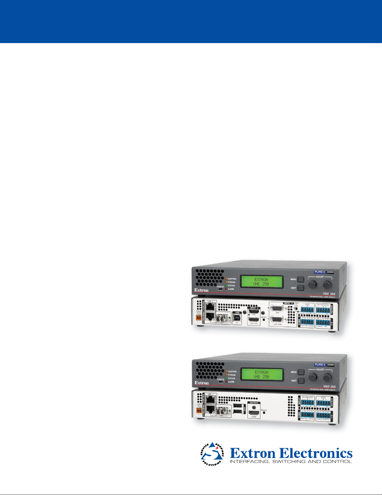
VN-Matrix® 250 Series
VNE 250 Encoder and VND 250 Decoder
User Guide
Streaming AV Products
68-2236-01 Rev. B
04 14
Page 2
Safety Instructions
Safety Instructions • English
WARNING: This symbol,
to alert the user of the presence of uninsulated dangerous voltage
within the product’s enclosure that may present a risk of electric shock.
ATTENTION: This symbol,
intended to alert the user of important operating and maintenance
(servicing) instructions in the literature provided with the equipment.
For information on safety guidelines, regulatory compliances, EMI/EMF
compatibility, accessibility, and related topics, see the Extron Safety and
Regulatory Compliance Guide, part number 68-290-01, on the Extron
website, www.extron.com.
, when used on the product, is intended
D
, when used on the product, is
I
Instructions de sécurité • Français
AVERTISSEMENT: Ce pictogramme,
le produit, signale à l’utilisateur la présence à l’intérieur du boîtier du
produit d’une tension électrique dangereuse susceptible de provoquer
un choc électrique.
ATTENTION: Ce pictogramme,
signale à l’utilisateur des instructions d’utilisation ou de maintenance
importantes qui se trouvent dans la documentation fournie avec le
matériel.
Pour en savoir plus sur les règles de sécurité, la conformité à la
réglementation, la compatibilité EMI/EMF, l’accessibilité, et autres sujets
connexes, lisez les informations de sécurité et de conformité Extron,
réf. 68-290-01, sur le site Extron, www.extron.com.
I
, lorsqu’il est utilisé sur
D
, lorsqu’il est utilisé sur le produit,
Sicherheitsanweisungen • Deutsch
WARNUNG: Dieses Symbol
darauf aufmerksam machen, dass im Inneren des Gehäuses dieses
Produktes gefährliche Spannungen herrschen, die nicht isoliert sind
und die einen elektrischen Schlag verursachen können.
VORSICHT: Dieses Symbol
in der im Lieferumfang enthaltenen Dokumentation besonders wichtige
Hinweise zur Bedienung und Wartung (Instandhaltung) geben.
Weitere Informationen über die Sicherheitsrichtlinien, Produkthandhabung,
EMI/EMF-Kompatibilität, Zugänglichkeit und verwandte Themen finden Sie
in den Extron-Richtlinien für Sicherheit und Handhabung (Artikelnummer
68-290-01) auf der Extron-Website, www.extron.com.
auf dem Produkt soll den Benutzer
D
auf dem Produkt soll dem Benutzer
I
Instrucciones de seguridad • Español
ADVERTENCIA: Este símbolo,
avisa al usuario de la presencia de voltaje peligroso sin aislar dentro del
producto, lo que puede representar un riesgo de descarga eléctrica.
ATENCIÓN: Este símbolo,
avisa al usuario de la presencia de importantes instrucciones de uso y
mantenimiento recogidas en la documentación proporcionada con el
equipo.
Para obtener información sobre directrices de seguridad, cumplimiento
de normativas, compatibilidad electromagnética, accesibilidad y temas
relacionados, consulte la Guía de cumplimiento de normativas y seguridad de
Extron, referencia 68-290-01, en el sitio Web de Extron, www.extron.com.
, cuando se utiliza en el producto,
D
, cuando se utiliza en el producto,
I
Инструкция по технике безопасности • Русский
ПРЕДУПРЕЖДЕНИЕ: Данный символ, D, если указан
на продукте, предупреждает пользователя о наличии
неизолированного опасного напряжения внутри корпуса
продукта, которое может привести к поражению
электрическим током.
ВНИМАНИЕ: Данный символ, I, если указан на продукте,
предупреждает пользователя о наличии важных инструкций
по эксплуатации и обслуживанию в руководстве,
прилагаемом к данному оборудованию.
Для получения информации о правилах техники безопасности,
соблюдении нормативных требований, электромагнитной
совместимости (ЭМП/ЭДС), возможности доступа и других вопросах
см. руководство по безопасности и соблюдению нормативных
требований Extron на сайте Extron: www.extron.com, номер по
каталогу - 68-290-01.
Chinese Simplified(简体中文)
警告: D产品上的这个标志意在警告用户该产品机壳内有暴露的危险 电压,
有触电危险。
注意:I 产品上的这个标志意在提示用户设备随附的用户手册中有
重要的操作和维护(维修)说明。
关于我们产品的安全指南、遵循的规范、EMI/EMF 的兼容性、无障碍
使用的特性等相关内容,敬请访问 Extron 网站 www.extron.com,参见 Extron
安全规范指南,产品编号 68-290-01。
Chinese Traditional( )
警告: D 若產品上使用此符號,是為了提醒使用者,產品機殼內存在著
可能會導致觸電之風險的未絕緣危險電壓。
注意I 若產品上使用此符號,是為了提醒使用者,設備隨附的用戶手冊中有重要
的 操 作 和 維 護( 維 修 )説 明 。
有關 安全性指 導方 針、法規 遵守、EMI/EMF 相容性、存取範圍和相關主題的詳細資訊,
請瀏覽 Extron 網站:www.extron.com,然 後 參 閱《 Extron 安全性與法規遵守手
冊 》,準 則 編 號 68-290-01。
Japanese
警告: この記号 D が製品上に表示されている場合は、筐体内に絶縁されて
いない高電圧が流れ、感電の危険があることを示しています。
注意:この記号 I が 製 品 上 に 表 示 さ れ て い る 場 合 は 、 本 機 の 取 扱 説 明 書 に 記 載 さ れ て
いる重要な操 作と保守(整備 )の指 示につ いてユーザーの 注意を喚起するものです。
安全上のご注意、法令遵守、EMI/EMF適合性、その他の関連項目に
つ い て は 、エ ク ストロ ン の ウェ ブ サイト www.extron.com より
『Extron Safety and Regulatory Compliance Guide』 (P/N 68-290-01) をご覧く
ださい。
Korean
경고: 이 기호 D, 가 제품에 사용될 경우, 제품의 인클로저 내에 있는
접지되지 않은 위험한 전류로 인해 사용자가 감전될 위험이 있음을
경고합니다.
주의: 이 기호 I, 가 제품에 사용될 경우, 장비와 함께 제공된 책자에 나와
있는 주요 운영 및 유지보수(정비) 지침을 경고합니다.
안전 가이드라인, 규제 준수, EMI/EMF 호환성, 접근성, 그리고 관련 항목에 대한
자세한 내용은 Extron 웹 사이트(www.extron.com)의 Extron 안전 및 규제 준수
안내서, 68-290-01 조항을 참조하십시오.
ii
Page 3

FCC Class A Notice
This equipment has been tested and found to comply with the limits for a Class A digital
device, pursuant to part15 of the FCC rules. The ClassA limits provide reasonable
protection against harmful interference when the equipment is operated in a commercial
environment. This equipment generates, uses, and can radiate radio frequency energy and,
if not installed and used in accordance with the instruction manual, may cause harmful
interference to radio communications. Operation of this equipment in a residential area is
likely to cause interference. This interference must be corrected at the expense of the user.
NOTE: For more information on safety guidelines, regulatory compliances, EMI/EMF
compatibility, accessibility, and related topics, see the Extron Safety and
Regulatory Compliance Guide on the Extron website.
Specifications Availability
Product specifications are available on the Extron website, www.extron.com.
Copyright
© 2014 Extron Electronics. All rights reserved.
Trademarks
All trademarks mentioned in this guide are the properties of their respective owners.
The following registered trademarks(®), registered service marks(
RGBSystems, Inc. or Extron Electronics:
Registered Trademarks
AVTrac, Cable Cubby, CrossPoint, eBUS, EDID Manager, EDID Minder, Extron, Flat Field, GlobalViewer, Hideaway, Inline, IP Intercom, IP
Link, Key Minder, LockIt, MediaLink, PlenumVault, PoleVault, PowerCage, PURE3, Quantum, SoundField, SpeedMount, SpeedSwitch,
SystemINTEGRATOR, TeamWork, TouchLink, V‑Lock, VersaTools, VN‑Matrix, VoiceLift, WallVault, WindoWall, XTP, XTP Systems
(SM)
Registered Service Mark
AAP, AFL (Accu‑Rate Frame Lock), ADSP (Advanced Digital Sync Processing), AIS (Advanced Instruction Set), Auto‑Image, CDRS (Class D
Ripple Suppression), DDSP (Digital Display Sync Processing), DMI (Dynamic Motion Interpolation), Driver Configurator, DSP Configurator, DSVP
(Digital Sync Validation Processing), FastBite, FOXBOX, IP Intercom HelpDesk, MAAP, MicroDigital, ProDSP, QS‑FPC (QuickSwitch Front Panel
Controller), Scope‑Trigger, SIS, Simple Instruction Set, Skew‑Free, SpeedNav, Triple‑ActionSwitching, XTRA, ZipCaddy, ZipClip
: S3 Service Support Solutions
Trademarks (™
SM
), and trademarks(TM) are the property of
(®)
)
iii
Page 4

Conventions Used in this Guide
In this user guide, the following are used:
WARNING: A warning warns of things or actions that might cause injury, death, or other
severe consequences.
CAUTION: A caution warns of things or actions that might damage the equipment.
ATTENTION: Attention indicates a situation that may damage or destroy the product or
associated equipment.
NOTE: A note draws attention to important information.
TIP: A tip provides a suggestion to make setting up or working with the device easier.
Commands are written in the fonts shown here:
^AR Merge Scene,,Op1 scene 1,1 ^B 51 ^W^C
[01] R 0004 00300 00400 00800 00600 [02] 35 [17] [03]
E X!*X1&*X2)*X2#*X2! CE}
NOTE: For commands and examples of computer or device responses mentioned
in this guide, the character “0” is used for the number zero and “O” represents the
capital letter “o”.
Computer responses and directory paths that do not have variables are written in the font
shown here:
Reply from 208.132.180.48: bytes=32 times=2ms TTL=32
C:\Program Files\Extron
Variables are written in slanted form as shown here:
ping xxx.xxx.xxx.xxx —t
SOH R Data STX Command ETB ETX
Selectable items, such as menu names, menu options, buttons, tabs, and field names are
written in the font shown here:
From the File menu, select New.
Click the OK button.
iv
Page 5

Contents
Introduction .................................................... 1
About this Guide .............................................. 1
About the VNM 250 ......................................... 1
VNM 250 System Controller ............................ 3
Transport Protocols Used for Streaming .......... 3
Multicast RTP — An Overview ..................... 4
Unicast RTP — An Overview ....................... 5
TCP — An Overview .................................... 5
Definitions ........................................................ 6
Features .......................................................... 6
Installation Overview ..................................... 9
Front Panels ................................................. 11
VNM 250 Front Panels................................... 11
Status Information ......................................... 12
Unit Identify Mode ......................................... 12
Rear Panel and Connections ...................... 13
VNE 250 Rear Panel ...................................... 13
VND 250 Rear Panel...................................... 13
Connections .................................................. 14
Power ........................................................ 14
Network Connections ................................ 15
USB Ports ................................................. 17
Coms ........................................................ 18
Alarms ....................................................... 19
TTL ............................................................ 19
Genlock ..................................................... 19
Video Connections .................................... 20
Audio Connections .................................... 21
Reset ......................................................... 21
System Configuration with the
Enterprise Controller ................................... 22
Controlling Your System with a
VN‑Matrix Enterprise Controller..................... 22
Low Level Device Configuration ................ 24
Setting a VNM 250 Device as the
System Controller ......................................... 27
Configuring the System Controller with a
Static IP Address ...................................... 27
Configuring Other VNM 250 Devices with
a Static IP Address ................................... 27
Configuring a VNM 250 Series Unit
for DHCP ...................................................... 28
Configuring a VNM 250 System Controller
as a DHCP Server .................................... 28
Configuring a VNM 250 Series Unit to
Operate with a DHCP Server .................... 29
Using a Dedicated DHCP Server ................... 30
Configuring a Windows 2008 R2. .................. 31
Control Port ................................................... 32
Configuring the Control port ....................... 32
VNM 250 GUI Overview ............................... 33
VNM 250 GUI Login ...................................... 33
VNM 250 GUI Tabs ........................................ 34
Tabs Shared by Both the Encoder and
Decoder ....................................................... 35
Encoder Tabs ................................................ 45
Video Stream Input Configuration .............. 46
Managing Compression and
Bandwidth Settings .................................. 48
Audio Stream Configuration ....................... 53
Audio Input Selection ................................. 54
Decoder Tabs ................................................ 57
Output Configuration ................................. 58
Configuration with the VNM 250 GUI .........66
Configuring a VNE 250 .................................. 66
Configuring Encoder Video ........................ 67
Managing Compression and
Bandwidth Settings .................................. 68
Bandwidth Management
– Simple Control ....................................... 68
Bandwidth Management
– Advanced Control .................................. 69
Configuring Encoder Audio ........................ 70
Configuring Encoder Data .......................... 71
VNM 250 • Contents v
Page 6

Configuring a VND 250 .................................. 72
Configuring the Decoder Display ................ 73
Monitoring the Decoder Video
Bandwidth ................................................ 74
Configuring the Decoder Audio .................. 75
Configuring the Decoder Data.................... 76
Custom Input and Output Modes .................. 77
Video Setup Page ...................................... 77
Custom Input Modes ................................. 79
Custom Output Modes .............................. 83
Upgrading Firmware ...................................... 87
Uploading the Firmware File to the
VNM 250 Controller .................................. 88
Installing the New Firmware ....................... 88
Configuring KVM Functionality ....................... 89
RS‑232 Pass‑through Configuration .............. 90
Pass‑through Coms Server
Configuration ............................................ 90
Pass‑through Coms Client
Configuration ............................................ 90
Alarms ........................................................111
Alarm Types ................................................. 111
Alarm Handling ............................................ 113
Troubleshooting ......................................... 114
Front Panel Status Indicators ....................... 115
Front Panel LCD Menu ................................ 115
Default Menu Screens (Encoder) .............. 116
Default Menu Screens (Decoder).............. 116
Controller Web User Interface ...................... 117
Troubleshooting Guide ................................. 117
No Web UI Pages Served ........................ 117
Device Not Listed in the
Device List Page ..................................... 118
Encoder — Input Signal (Video) Issues ..... 118
Decoder — Problems with Viewing
the Decoded Image ................................ 119
Program Audio Problems ......................... 120
Return Audio Problems ............................ 121
Front Panel Menu Configuration ................ 91
Front Panel Menu Overview ........................... 91
Configuring the VNE 250 Encoder ................. 91
Default Menu Screens................................ 91
Top Level Menu ......................................... 92
Encode Config Sub‑menu ......................... 93
OSD Sub‑menu ......................................... 94
Network Sub‑menu ................................... 94
Input Sub‑menu......................................... 96
EDID Sub‑menu ........................................ 97
Test Pattern Sub‑menu .............................. 98
Reset Sub‑menu ....................................... 99
Configuring the VND 250 Decoder............... 100
Default Menu Screens.............................. 100
Top Level Menu ....................................... 101
Decode Config Sub‑menu ....................... 102
OSD Sub‑menu ....................................... 103
Network Sub‑menu ................................. 103
Output Sub‑menu .................................... 106
Video Wall Sub‑menu .............................. 107
Test Pattern Sub‑menu ............................ 108
Genlock Sub‑menu.................................. 109
Reset Sub‑menu ..................................... 109
Reference Material .................................... 122
Supported EDID Modes............................... 122
DVI .......................................................... 122
HDMI ....................................................... 122
VGA ......................................................... 123
VN‑Matrix System Port Usage ..................... 123
SIS Commands ..........................................125
Introduction to SIS ....................................... 125
Host‑to‑Device Communications ............. 125
Symbols Used in this Guide ......................... 125
Error Messages ........................................... 126
Command and Response Table for
SIS Commands .......................................... 127
Mounting ....................................................129
Choosing a Suitable Location for
Mounting .................................................... 129
Environmental Requirements ....................... 129
Orientation ............................................... 129
Temperature ............................................ 129
Ventilation ................................................ 129
Humidity and water .................................. 130
Mounting Procedures .................................. 130
Tabletop Use ........................................... 130
Rack‑Mounting ........................................ 130
VNM 250 • Contents vi
Page 7

Introduction
This section provides an overview of the user guide and describes the Extron
VN‑Matrix (VNM) 250 series. Topics that are covered include:
z About this Guide
z About the VNM 250
z VNM 250 System Controller
z Transport Protocols Used for Streaming
z Definitions
z Features
About this Guide
The VN‑Matrix 250 (VNM 250) series consists of the VNE 250 encoder and the VND 250
decoder. This guide contains installation, configuration, and operating information for both
the encoder and the decoder.
In this guide:
z The term "encoder" refers specifically to the VNE 250 encoder.
z The term "decoder" refers specifically to the VND 250 decoder.
z The term "stream" refers to multimedia that is constantly received by (and normally
presented to) an end‑user while being delivered by a VN‑Matrix encoding device.
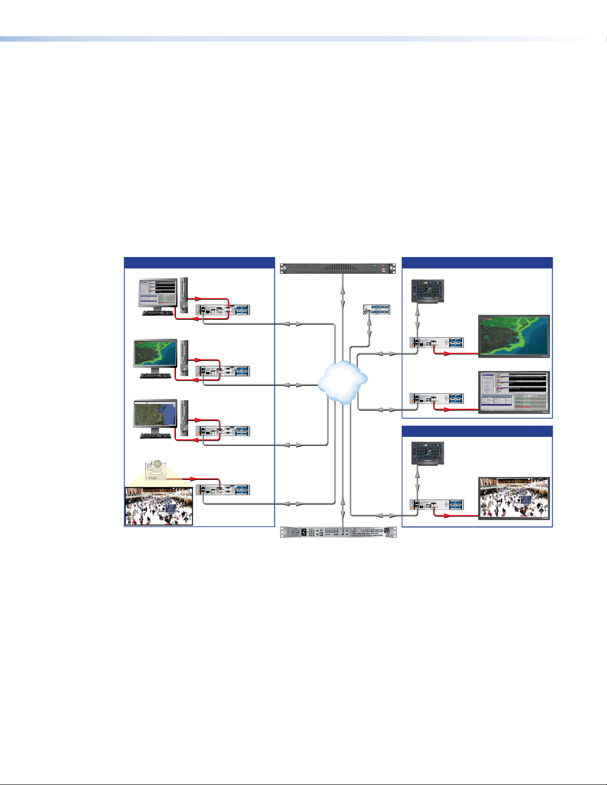
About the VNM 250
The VNE 250 distributes video, audio, and data input across an IP network to one or
more VND 250 decoders. Transport across the network must be coordinated by a
control device. For a small system (ten devices or fewer connected to the network) the
controller can be another VNM 250 (either an encoder or a decoder). For larger systems,
aVNMEnterpriseController is required.
The VNE 250 encodes video, audio, and data inputs into PURE3 data streams for transport
across a local area or wide area network. Elsewhere on the network one or more VND 250
units decode the stream.
VNE 250 inputs can include:
z Analog (VGA) video
z Digital (HDMI) video
z Analog audio
z Digital audio that is contained in an HDMI signal.
z Serial (RS‑232) and UDP data
z USB connections for remote mouse and keyboard
The individual video, audio, and data streams are synchronized and treated as a single
logical stream.
VNM 250 • Introduction 1
Page 8
The VNM 250 series also supports a reverse audio channel for collaborative applications
where 2‑way communication is required.
The VND 250 video output is available only in digital format. It can be configured to display
at the same resolution and refresh rate as the encoder input or it can be scaled to match the
requirements of the display attached to the decoder.
The decoder supports both digital audio, analog audio, or both. The audio output is
independent of the encoder audio source.
UDP network data originating from an external source is streamed along with the video and
audio content to the appropriate decoder, where it is extracted for onward processing.
RS‑232 pass‑through data transport is full duplex. It can originate at either the encoder or
decoder and may be sent to multiple destinations. It passes through the system unchanged
and may not be recorded.
Figure 1 shows a typical application for the VNM 250.
Extron
Encoded Inputs Location 1 Decoding
Extron
VNE 250 Matrix
VN-Matrix Encoder
RGB
HDMI/RGB
LOOP
RETURN AUDIO
AUDIO
INPUT 2
LAN 1
POWER
12V
-A MAX
PC
STREAMINGCONTROL
RGB
HDMI
LAN 1
POWER
12V
-A MAX
PC
STREAMINGCONTROL
HDMI
HDMI
LAN 1
POWER
12V
-A MAX
PC
STREAMINGCONTROL
HDMI
HD PTZ Camera
HDMI
LAN 1
POWER
12V
-A MAX
STREAMINGCONTROL
INPUT 1
RGB
USB
HDMI
RESET
ACT/
LINK
LOOP THRU LOOP THRU
PC
LAN 2
Extron
VNE 250 Matrix
VN-Matrix Encoder
HDMI/RGB
INPUT 2
INPUT 1
RGB
USB
HDMI
RESET
ACT/
LINK
LOOP THRU LOOP THRU
PC
LAN 2
Extron
VNE 250 Matrix
VN-Matrix Encoder
HDMI/RGB
INPUT 2
INPUT 1
RGB
USB
HDMI
RESET
ACT/
LINK
LOOP THRU LOOP THRU
PC
LAN 2
Extron
VNE 250 Matrix
VN-Matrix Encoder
HDMI/RGB
INPUT 2
INPUT 1
RGB
USB
HDMI
RESET
ACT/
LINK
LOOP THRU LOOP THRU
PC
LAN 2
THRU
OUTPUT
L
R
LR
TxRx
GTxRxNOG IN GOUT
I/O
COMS
PASS THRUALARM TTLCONTROL
LOOP
RETURN AUDIO
AUDIO
THRU
OUTPUT
LR
L
R
TxRx
GTxRxNOG IN GOUT
I/O
COMS
PASS THRUALARM TTLCONTROL
LOOP
RETURN AUDIO
AUDIO
THRU
OUTPUT
LR
L
R
TxRx
GTxRxNOG IN GOUT
I/O
COMS
PASS THRUALARM TTLCONTROL
LOOP
RETURN AUDIO
AUDIO
THRU
OUTPUT
LR
L
R
TxRx
GTxRxNOG IN GOUT
I/O
COMS
PASS THRUALARM TTLCONTROL
VN-Matrix Enterprise Controller
Ethernet
Ethernet
Ethernet
Ethernet
Ethernet
Switching
Ethernet
IP
Network
Virtual
Ethernet
Extron
IPL 250
IP Link Control
Processor
COM1
COM 2 IR
RELAY
2
2
1
1
TxRx
RTS CTS
TxRx
SGSG
POWER
LAN
12V
500mA
INPUT
COM 3 IR
RELAY
MAX
4
4
3
3
TxRx
1234
SGSG
Ethernet
Ethernet
Ethernet
Extron
TLP 1000TV
10" Tabletop
TouchLink
Touchpanel
Ethernet
Extron
VND 250 Matrix
VN-Matrix Decoder
HDMI/RGB
RETURN AUDIO
LAN 1
POWER
12V
-A MAX
ACT/
LINK
LAN 2
STREAMINGCONTROL
Extron
VND 250 Matrix
VN-Matrix Decoder
HDMI/RGB
LAN 1
POWER
12V
-A MAX
ACT/
LINK
LAN 2
STREAMINGCONTROL
AUDIO
OUTPUT
1
USB
2
OUTPUT
1
USB
2
OUTPUT
R
R
L
L
GTxRxNOG IN GOUT
TxRx
RESET
I/O
COMS INPUT
PASS THRUALARMGENLOCKCONTROL
HDMI
RESET
HDMI
HDMI
RETURN AUDIO
AUDIO
OUTPUT
R
R
L
L
TxRx
GTxRxNOG IN GOUT
I/O
COMS INPUT
PASS THRUALARMGENLOCKCONTROL
HDMI
Location 2 Decoding
Extron
TLP 1000TV
10" Tabletop
TouchLink
Touchpanel
Ethernet
Extron
VND 250 Matrix
VN-Matrix Decoder
HDMI/RGB
RETURN AUDIO
LAN 1
POWER
12V
-A MAX
ACT/
LINK
LAN 2
STREAMINGCONTROL
AUDIO
OUTPUT
1
USB
2
OUTPUT
LR
L
R
TxRx
GTxRxNOG IN GOUT
RESET
I/O
COMS INPUT
PASS THRUALARMGENLOCKCONTROL
HDMI
HDMI
MODEL 80
MODEL 80
MODEL 80
Flat Panel Display
FLAT PANEL
Flat Panel Display
FLAT PANEL
Flat Panel Display
FLAT PANEL
Extron
VNR 100
VN-Matrix Recorder
Figure 1. A Typical VNM 250 Application
VNM 250 • Introduction 2
Page 9

VNM 250 System Controller
All Matrix systems require one device that acts as the system controller. For small systems
(ten devices or fewer), this can be either a VNE 250 or VND 250. For larger systems, a
VN‑Matrix Enterprise Controller must be used.
Systems Controlled by
VNMEnterpriseController
The VNM Enterprise Controller is able to
control all VN‑Matrix systems (large and small)
but is required for large systems (more than
10 devices).
The system is controlled through a powerful
web‑based user interface served from the
Enterprise Controller.
Supports all VN‑Matrix devices, including
recorders.
NOTES:
• A small system that includes a VNM 250 device must be controlled by either a
VNMEnterprise Controller or a VNM 250 device.
• If an incompatible VN‑Matrix device is added to a small system controlled by a
VNM250 device, the controller is unable to detect or control that device.
Transport Protocols Used for Streaming
The source data from a VN‑Matrix encoder can be distributed to multiple displays/decoders
(one‑to‑many) or to a single display/decoder (point‑to‑point). A previously recorded stream
can be distributed in the same way and may be thought of as an encoder in this context.
A stream may be transported from the source (encoder, recorded stream) to the display
(decoder) using one of three methods:
z See Multicast Real-time Transport Protocol (RTP) on page 4.
z See Unicast Real-time Transport Protocol (RTP) on page 5.
z See Transmission Control Protocol (TCP) on page 5.
Systems Controlled by
VNM250Device
A VNM 250 device can control small systems
(10 devices or fewer). It is less effective as the
system size increases.
The system is controlled through a more
limited web‑based user interface served from
the VNM250 controller device.
Supports VNM 250 encoders and decoders
and PCs running the VNS 104 software
decoder. Does not support recorders.
VNM 250 • Introduction 3
Page 10
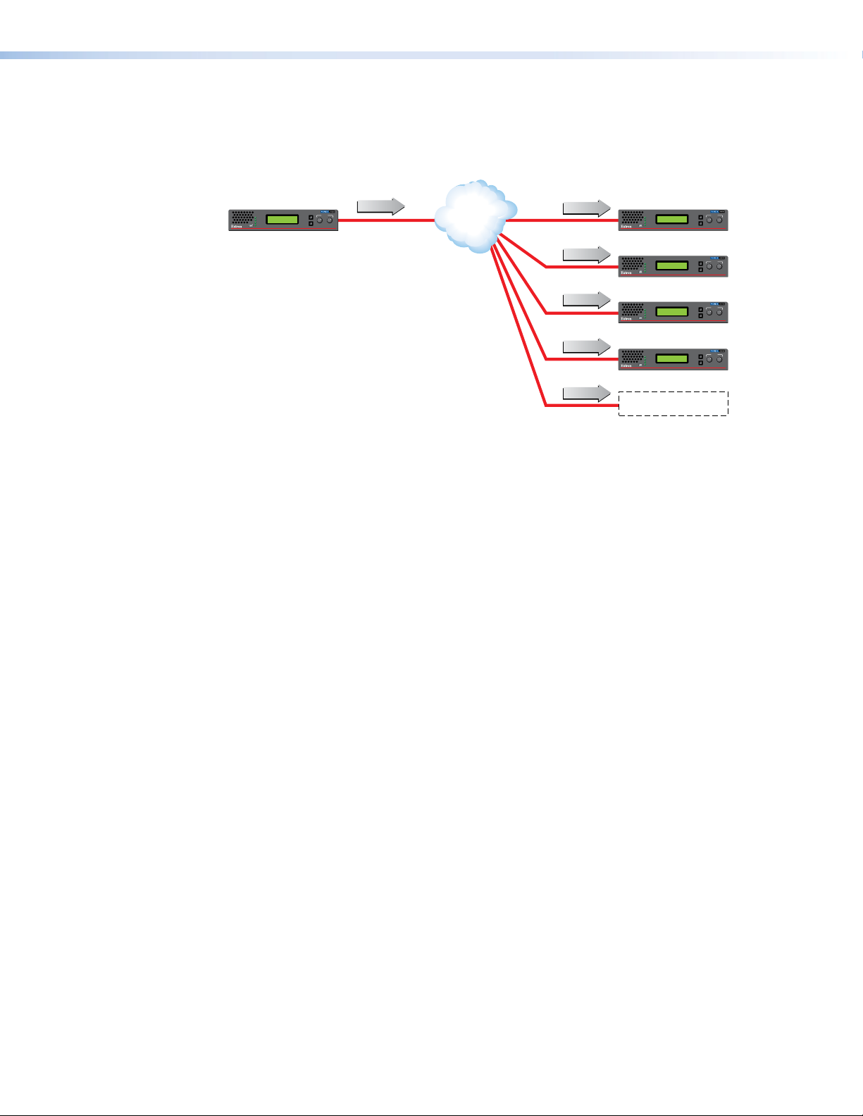
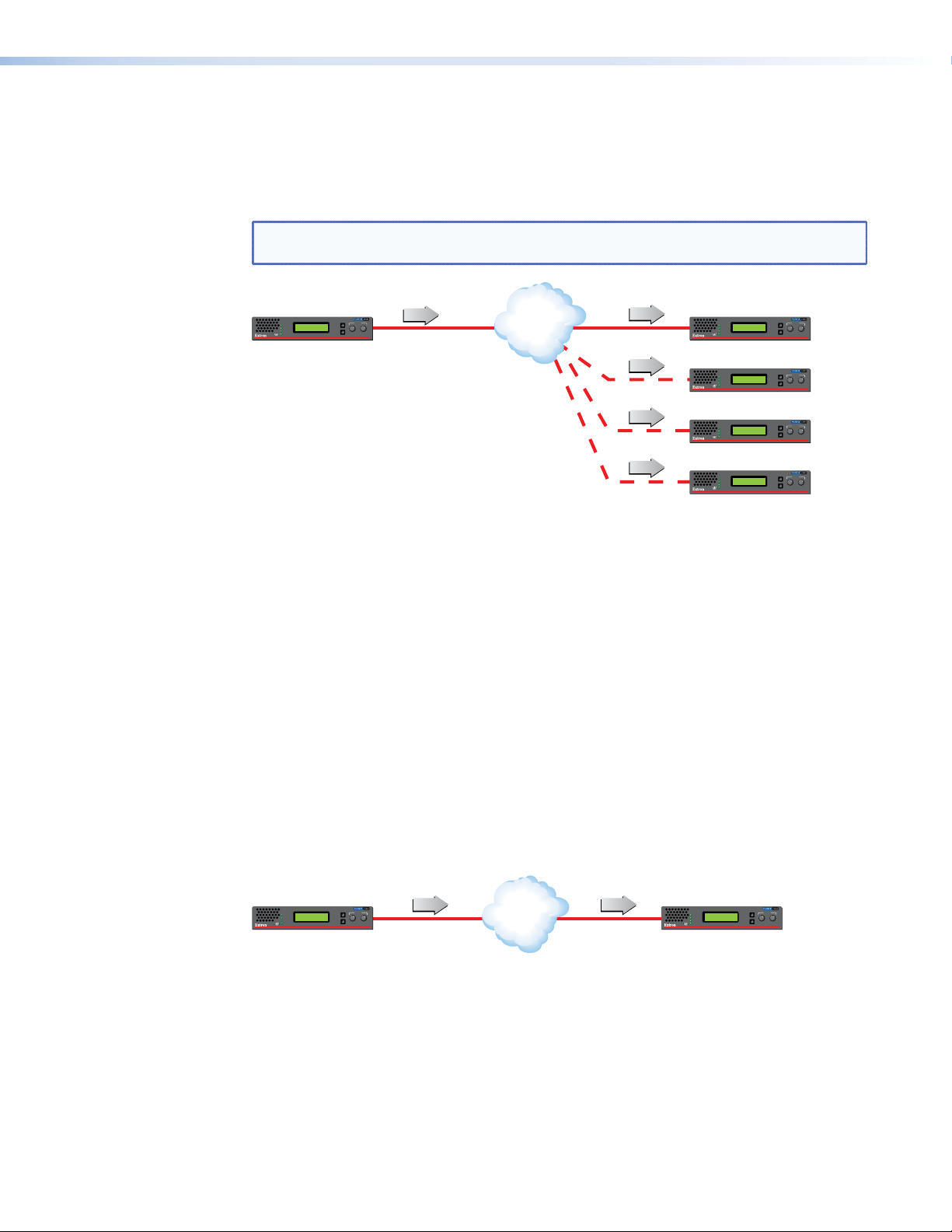
Multicast RTP — An Overview
DISPLAYS
Encoder sends data using
to a multicast gr
oup.
Multicast RTP allows a source to be displayed on multiple displays. This method uses a
real‑time variation of UDP (User Datagram Protocol) called RTP (Real‑time Transport
Protocol).
CONTROL
STREAM
STATUS
CONFIG
ALARM
SOURCE
MENU
NEXT
ADJUST
VN-MATRIX RGB / HDMI OVER IP
oup.
RTP (m)
VNE 250
Network
RTP
RTP (m)
RTP (m)
RTP (m)
RTP (m)
ADJUST
CONTROL
STREAM
STATUS
CONFIG
ALARM
CONTROL
STREAM
STATUS
CONFIG
ALARM
CONTROL
STREAM
STATUS
CONFIG
ALARM
CONTROL
STREAM
STATUS
CONFIG
ALARM
MENU
NEXT
VND 250
VN-MATRIX RGB / HDMI OVER IP
ADJUST
MENU
NEXT
VND 250
VN-MATRIX RGB / HDMI OVER IP
ADJUST
MENU
NEXT
VND 250
VN-MATRIX RGB / HDMI OVER IP
ADJUST
MENU
NEXT
VND 250
VN-MATRIX RGB / HDMI OVER IP
RTP (m)
Multiple decoders can be
part of the multicast gr
Figure 2. Multicast RTP Streaming
The source encoder uses RTP to send data to a multicast group. The source does not need
to know the IP address of the decoders that are using the source.
RTP provides very low latency which is important for video streaming. Unlike other
protocols, RTP packets include a time stamp. If packets are received in the wrong
order, they are sorted into the correct order for display or discarded if the time stamp is
out‑of‑date.
However, because RTP is a connectionless protocol, data delivery is not guaranteed.
When data packets are lost (for example, due to excessive network traffic), the
VNM 250 devices carefully manage the data stream to minimize any image disruption.
VNM 250 • Introduction 4
Page 11
Unicast RTP — An Overview
DISPLAYS
SOURCE
DISPLAY
Encode
Similar to multicast RTP, this method uses a real‑time variation of UDP protocol, called
unicast RTP. This method can be used where the network infrastructure does not support
multicast traffic. Typically, this protocol is used for point‑to‑point configuration (single source
to single display), but can be configured to use up to a maximum of four displays.
NOTE: The encoder sends an individual stream to each decoder. This means that the
total bandwidth of the VN‑Matrix system increases as more decoders are added.
ADJUST
CONTROL
STREAM
STATUS
CONFIG
ALARM
MENU
NEXT
VN-MATRIX RGB / HDMI OVER IP
RTP (1-4)
VNE 250
Encoder sends data using RTP
to up to 4 specified decoders.
SOURCE
Network
RTP 1
RTP 2
RTP 3
RTP 4
ADJUST
CONTROL
STREAM
STATUS
CONFIG
ALARM
CONTROL
STREAM
STATUS
CONFIG
ALARM
CONTROL
STREAM
STATUS
CONFIG
ALARM
CONTROL
STREAM
STATUS
CONFIG
ALARM
MENU
NEXT
VND 250
VN-MATRIX RGB / HDMI OVER IP
ADJUST
MENU
NEXT
VND 250
VN-MATRIX RGB / HDMI OVER IP
ADJUST
MENU
NEXT
VND 250
VN-MATRIX RGB / HDMI OVER IP
ADJUST
MENU
NEXT
VND 250
VN-MATRIX RGB / HDMI OVER IP
Figure 3. Unicast RTP Streaming
RTP provides very low latency which is important for video streaming. Unlike other
protocols, RTP packets include a time stamp. If packets are received in the wrong
order, they are sorted into the correct order for display or discarded if the time stamp is
out‑of‑date.
However, because RTP is a connectionless protocol, data delivery is not guaranteed.
When data packets are lost (for example, due to excessive network traffic), the
VNM 250 devices carefully manage the data stream to minimize image disruption.
TCP — An Overview
This method transports data using standard TCP (Transmission Control Protocol) and
should only be used for single point‑to‑point transfer of data.
TCP is a connection‑based protocol and, therefore, data is guaranteed to be delivered.
However, in the event of excessive network traffic, delivery may be delayed which
impacts real‑time performance. Therefore, TCP transport should be avoided for streaming
applications.
ADJUST
CONTROL
STREAM
STATUS
CONFIG
ALARM
MENU
NEXT
VNE 250
VN-MATRIX RGB / HDMI OVER IP
TCP TCP
r
Figure 4. TCP Streaming
Network
ADJUST
CONTROL
STREAM
STATUS
CONFIG
ALARM
Decoder makes a
TCP connection with
a specified encoder.
MENU
NEXT
VND 250
VN-MATRIX RGB / HDMI OVER IP
VNM 250 • Introduction 5
Page 12

Definitions
PURE3 — is specifically designed for network transmission of real time media (such as
video or graphics, audio, data, and whiteboard elements). It features both spatial and
temporal image compression, which allows for efficient bandwidth usage.
z PURE3 streams always contain video or graphic elements.
z PURE3 streams may also contain audio and data content that is associated with the
video and graphic elements.
Media (stream) — refers to multimedia that is constantly received by (and normally
presented to) an end‑user while being delivered by a streaming provider. Internet television
is a commonly streamed medium. Streaming media (stream) in this guide refers to a PURE3
media stream that is produced by a VN‑Matrix encoding device.
Device license — refers to the number of licensed features that are available on a device
within a VN‑Matrix system. All devices contain a license that offers a default level of
functionality. Device licenses cannot be modified.
Controller license — refers to the license that is set on the device designated as the
system controller. The Controller license enables the use of VN‑Matrix software decoders.
Controller licenses may be modified to suit changing system requirements.
UDP data — refers to the transfer of serial data between an encoder and a decoder. Data
input is created at the encoder, placed into the PURE3 stream, and sent to the decoder. The
data is received in the same form that it was transmitted. This method of data transfer is
unidirectional and can only be sent from an encoder to a decoder.
High-Level Interface (HLI) — is the command protocol that is used to communicate
between the VNM Enterprise Controller and an external control system.
Display Monitor Timings (DMT) — a list of VESA standard pre‑defined timings which are
commonly used within the computer industry.
Coordinated Video Timings (CVT) — the newest VESA standard for generating display
timings (released on March 2003).
Generalized Timing Formula (GTF) — a method of generating industry standard timings
used by a wide variety of display products.
Features
Stream at native resolutions up to 1920x1200 and 2048x1080 — compatible with
signals used in high‑resolution display applications.
Low latency streaming — 35 ms encode and 35 ms decode — Supports natural
interaction, bi‑directional communication, or remote device control in real‑time operating
environments.
SFP port for use with optical Ethernet transceivers — provides the option to use an
optical Ethernet network interface to optically isolate a source or eliminate electro‑magnetic
emissions in secure applications.
Extensive bit rate management — uses compression and bit rate management controls
to tune image quality and bit rate to fit a variety of application and network requirements.
High immunity to network errors — AV streaming maintains reliable, high quality imagery,
concealing errors even during heavy packet loss.
Unicast or multicast streaming — supports scalability and compatibility with different
network operating conditions.
PURE3 Codec — low‑latency, visually lossless compression offering efficient bit rates, and
high immunity to network errors for streaming very high quality video with low delay over IP
networks.
VNM 250 • Introduction 6
Page 13

Synchronization of multiple streams of audio, video, or both — audio and video
timing is maintained from a source across encoders preserving lip sync quality and
supporting multi‑source streaming applications.
Decoder genlock connection for synchronized decoding — supports synchronized
decoding of source streams across multiple VND 250 decoders.
EDID emulation — provides selectable resolutions and refresh rates, ensuring optimal
resolution and format between video sources, encoders or decoders, and displays.
Auto-Image setup — when activated, the unit automatically detects the resolution of
the incoming video signal and sets the total pixels, active pixels, and active lines, as well
as the horizontal and vertical starting points. This can save time and effort in setting up a
newly connected source, particularly in presentation environments where the input is not
connected to a fixed source, but instead goes to an open connection for a presenter’s
laptop.
Decode at native resolution or scale to match display resolution — configure
decoders to output the original source resolution or to scale incoming streams to match the
display resolution and maintain clean switches when new source streams are selected.
Aspect ratio control — the aspect ratio of the decoder output can be controlled by
selecting a FILL mode, which provides a full screen output, or a FOLLOW mode, which
preserves the original aspect ratio of the original source signal.
HDMI compliant — both the encoder and decoder support RGB and YCrCb source
formats.
HDCP compliant streaming — supports streaming of HDCP‑encrypted signals commonly
used in AV environments.
Key Minder continuously verifies HDCP compliance — authenticates and maintains
continuous HDCP encryption from sources to encoders and decoders to displays ensuring
reliable streaming of HDCP compliant displays.
HDCP Visual Confirmation provides a green signal when encrypted content is sent
to a non-compliant display — a full‑screen green signal is sent when HDCP‑encrypted
content is transmitted to a non‑HDCP compliant display, providing immediate visual
confirmation that protected content cannot be viewed on the display.
Audio —the VNM 250 incorporates:
z Bi‑directional audio streaming. Two‑way audio streaming supports bi‑directional audio
communication between encoders and decoders.
z HDMI embedded audio and analog stereo encoder inputs.
z HDMI audio embedding or de‑embedding by decoder. Audio signals can be embedded
onto the HDMI output signal or extracted to the analog stereo output.
z Audio breakaway streaming. Stream audio to decoders independently of associated
video sources. (This feature requires a VNM Enterprise Controller.)
Alarm relay — provides contact closure notice of warnings or alarms to control systems for
proactive system monitoring and fault resolution.
Front panel LCD interface, buttons, and rotary encoders — provide access and
control over device status and system data, simplifying system setup and operation.
Front panel LEDs — offers quick visual indication of device, system, or streaming status to
simplify commissioning activities and troubleshooting.
VLAN Tagging — simplifies management of encoders and decoders, making management
and operation on multi‑purpose networks simple.
Local Ethernet control port — offers the flexibility to connect a control device to the
VN‑Matrix 250 unit simplifying network cabling for the streaming system.
VNM 250 • Introduction 7
Page 14

USB connectors for configuration — a USB mini‑B port on the front panel can be
connected to a local PC for low level configuration.
USB Keyboard and Mouse streaming — rear panel USB connections are provided to
allow for KVM type collaboration between an encoder and decoder pair. The encoder USB
ports allow connection to a local PC, while the decoder USB ports allow connection of a
mouse and keyboard to remotely control a PC connected to the encoder.
On-screen display — aids in identifying system connections and simplifies troubleshooting
and programming activities.
System management with VNM Enterprise Controller — simplifies management and
control of systems with many VN‑Matrix devices.
Compatible and interoperable with VN-Matrix 200 and 225 models — preserves the
value of prior investment in VN‑Matrix products.
Serial RS-232 data streaming — manage RS‑232 serially controlled devices across
VN‑Matrix 250 connections.
Smart power management for encoder, decoder, source, and display operation —
configure encoder, decoder, or display to manage operation and sleep mode for continuous
operation or energy management, lowering heat, and saving energy and operating costs.
VNM 250 • Introduction 8
Page 15

Installation Overview
This section provides an overview of the installation process. To set up the VNE 250 and
VND 250, follow these instructions and the instructions referenced by the links provided:
1. If required, install small form‑factor pluggable (SFP) connectors in the LAN 2 ports (see
Streaming Network on page16).
2. Select a suitable location and mount the VNM 250 devices (see Mounting on
page129). Depending on your system, there may be multiple locations and multiple
units at each location.
3. Power on the VNM 250 devices by connecting the provided power supplies (see
page14). Do not connect the devices to a network.
4. Decide which device will be the system controller. For large systems (more than
10devices, you must use a VN‑Matrix Enterprise Controller. To configure the system
using the Enterprise Controller, see the VN-Matrix Enterprise Controller User Guide at
www.extron.com).
For smaller systems, you may use the Enterprise Controller or a VNM250 unit as the
controller (see Low Level Device Configuration on page 24).
5. Connect the Control connectors of the rear panel Coms port (three poles of the 5‑pole
captive screw connector) to a control computer. Use DataViewer to configure the IP
addresses for both the control port and streaming port, the subnet mask, and gateway
for each unit (see Low Level Device Configuration on page 24).
ATTENTION: Prepare thoroughly before connecting or configuring the VNM250
for an existing network. Contact your network administrator to ensure you
have the correct network information for each device that is being added to the
network. Incorrect connection or configuration may disrupt the network.
NOTE: Extron recommends configuring the IP addresses through the Coms port
on the rear panel. Alternatively, it is possible to use SIS commands (through the
USB on the front panel) or the front panel menu.
6. Connect all the VNM 250 units to the network (see Network Connections on
page15).
NOTES:
• Ensure that the LAN 2 port is connected to the designated streaming
network.
• The control port is used with IP Link or third‑party control devices. A control
port connection is not required for normal operation of the VNM 250 unit.
7. Connect the video sources to the encoders and display equipment to the decoders (see
Video Connections on page 20).
VNM 250 • Installation Overview 9
Page 16

8. Connect the audio sources to the encoders and the audio outputs to the decoders. If
required, connect the reverse audio input to the decoder and the reverse audio output
to the encoder (see Audio Connections on page 21).
NOTE: The reverse audio feature allows users at the decoder site to communicate
with users at the encoder site.
9. If required, connect USB cables to allow KVM Function. This allows users at the
decoder site to take control of the keyboard and mouse of the source computer at the
encoder site (see page 17).
10. If required, connect the encoder loop‑through video (see Video Connections on page
20) and audio (see Audio Connections on page 21) outputs.
11. If required, set up Genlock connections to synchronize the video streams to multiple
displays (see page 19).
12. Use a PC or laptop to access the web interface served by the controller.
For larger systems, see the VN-Matrix Enterprise Controller User Guide. For smaller
systems, see VNM 250 GUI Overview on page 33.
13. Configure the video and audio input and output properties for all the devices, using the
appropriate GUI web interface.
NOTE: Extron recommends configuring the audio and video connections through
the GUI web interface. Alternatively, it is possible to use the front panel menu.
VNM 250 • Installation Overview 10
Page 17
Front Panels
AE
This section describes
z VNM 250 Front Panels
z Status Information
z Unit Identify Mode
VNM 250 Front Panels
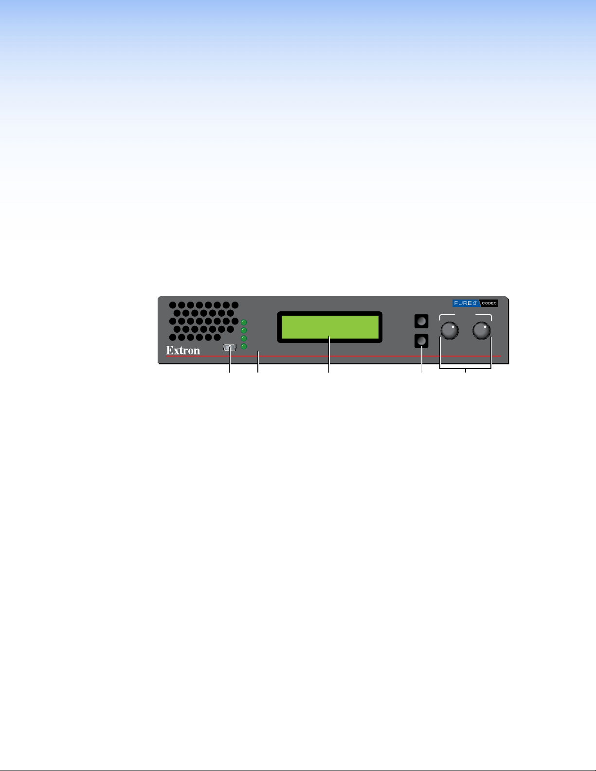
The front panels of both the VNE 250 and the VND 250 are identical apart from the product
name on the silk screen. The VNE 250 is shown below:
ADJUST
VN-MATRIX RGB / HDMI OVER IP
VNE 250
CONFIG
CONTROL
STREAM
STATUS
ALARM
MENU
NEXT
DCB
Figure 5. VNE 250 Front Panel
Config port — connect this USB mini type B port to a control PC for low level
A
configuration using SIS commands.
Unit status LEDs — provide status information about the unit (see Status Information
B
on the following page).
LCD display — A 2 x 16 character LCD display provides status feedback and allows
C
configuration through the front panel menu. For information about using the Front
Panel Menu Configuration, see page 91.
Menu and Next buttons — use these buttons to move through different levels of the
D
front panel menu.
Rotary encoders — use these rotary encoders to select values from the front panel
E
menu choices.
VNM 250 • Front Panels and Menus 11
Page 18

Status Information
Name Color Function
Control Orange Indicates the status of the control network port:
Stream Orange Indicates the status of the active network port (streaming):
Status Green Indicates the status of the VNE 250 or VND 250
Alarm Red Fully lit — indicates that a critical alarm has occurred.
For complete information, see Alarm Types on page 111.
Fully lit or Flashing intermittently — control data is being
transmitted or received by the port.
Unlit — no data or no network connection detected.
Fully lit or Flashing intermittently — system control or source data
is being transmitted or received by the port.
Unlit — no data or no network connection detected.
Condition Encoder (source) Decoder (display)
Unlit No source input detected. No stream being received.
Flashing Source being streamed. Stream being received.
Fully Lit Source present but not
being streamed (for
example, the unit is
currently disabled or in
standby mode).
Flashing — indicates an over‑temperature condition.
N/A
Unit Identify Mode
In addition to the standard indicator modes described above, there is a Unit Identify
mode, for troubleshooting. In large systems, with multiple units in a rack and multiple rack
locations, this is not always easy. The Unit Identify mode causes the front panel display back
light to illuminate and flash and makes it easy to match the physical unit in a rack with the
virtual unit displayed in the VN‑Matrix Enterprise Controller GUI.
The mode can only be triggered by a command from the Enterprise Controller. It is not
available in smaller systems where a VNM250 device is used as a controller.
VNM 250 • Front Panels and Menus 12
Page 19
Rear Panel and
ABCPDTSRNEMGH JK
ABCD FUSROJI
Q
Connections
This section describes the VNE 250 and VND 250 rear panels and the connectors:
z VNE 250 Rear Panel
z VND 250 Rear Panel
z Connections
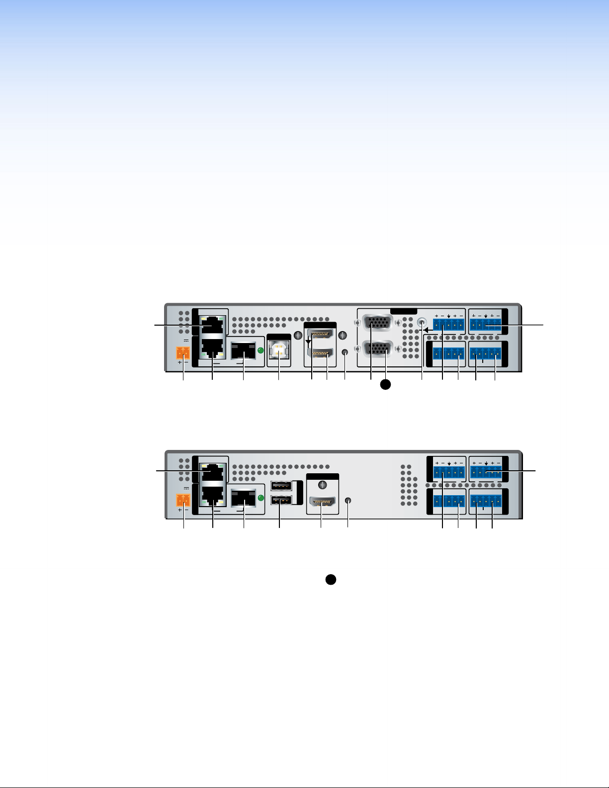
VNE 250 Rear Panel
LAN 1
POWER
12V
2.0 A MAX
STREAMINGCONTROL
LAN 2
/ACT
USB
LINK
PC
INPUT 1
HDMI
RESET
LOOP THRU LOOP THRU
RGB
INPUT 2
LOOP
THRU
AUDIO
L
R
Tx Rx
GTxRxNOC IN GOUT
COMS
PASS THRU ALARM TTLCONTROL
RETURN AUDIO
L R
OUTPUT
I/O
Figure 6. VNE 250 Rear Panel
VND 250 Rear Panel
POWER
12V
2.0 A MAX
Figure 7. VND 250 Rear Panel
Power
A
Control Network RJ‑45 connector
B
Streaming Network RJ‑45 connector
C
Streaming Network SFP connector (optional)
D
USB port, type B (VNE 250)
E
USB ports, type A (VND 250)
F
HDMI input (VNE 250)
G
HDMI loop‑through (VNE 250)
H
HDMI output (VND 250)
I
Reset button
J
Analog video input (VNE 250)
K
LAN 1
STREAMINGCONTROL
LAN 2
/ACT
L
RETURN AUDIO
OUTPUT
1
USB
2
LINK
RESET
HDMI
L
Analog video loop‑through (VNE 250)
Program audio loop‑through (VNE 250)
M
Program audio input (VNE 250)
N
Return audio input (VND 250)
O
Return audio output (VNE 250)
P
Program audio output (VND250)
Q
RS‑232 coms (low level configuration and pass
R
L
Tx Rx
GTxRxNOG IN GOUT
COMS INPUT
PASS THRU ALARM GENLOCKCONTROL
R
AUDIO
LR
OUTPUT
I/O
through)
Alarm relay
S
TTL (VNE 250: not implemented)
T
Genlock (VND 250)
U
VNM 250 • Rear Panel and Connections 13
Page 20
POWER
Smooth
AA
.
Connections
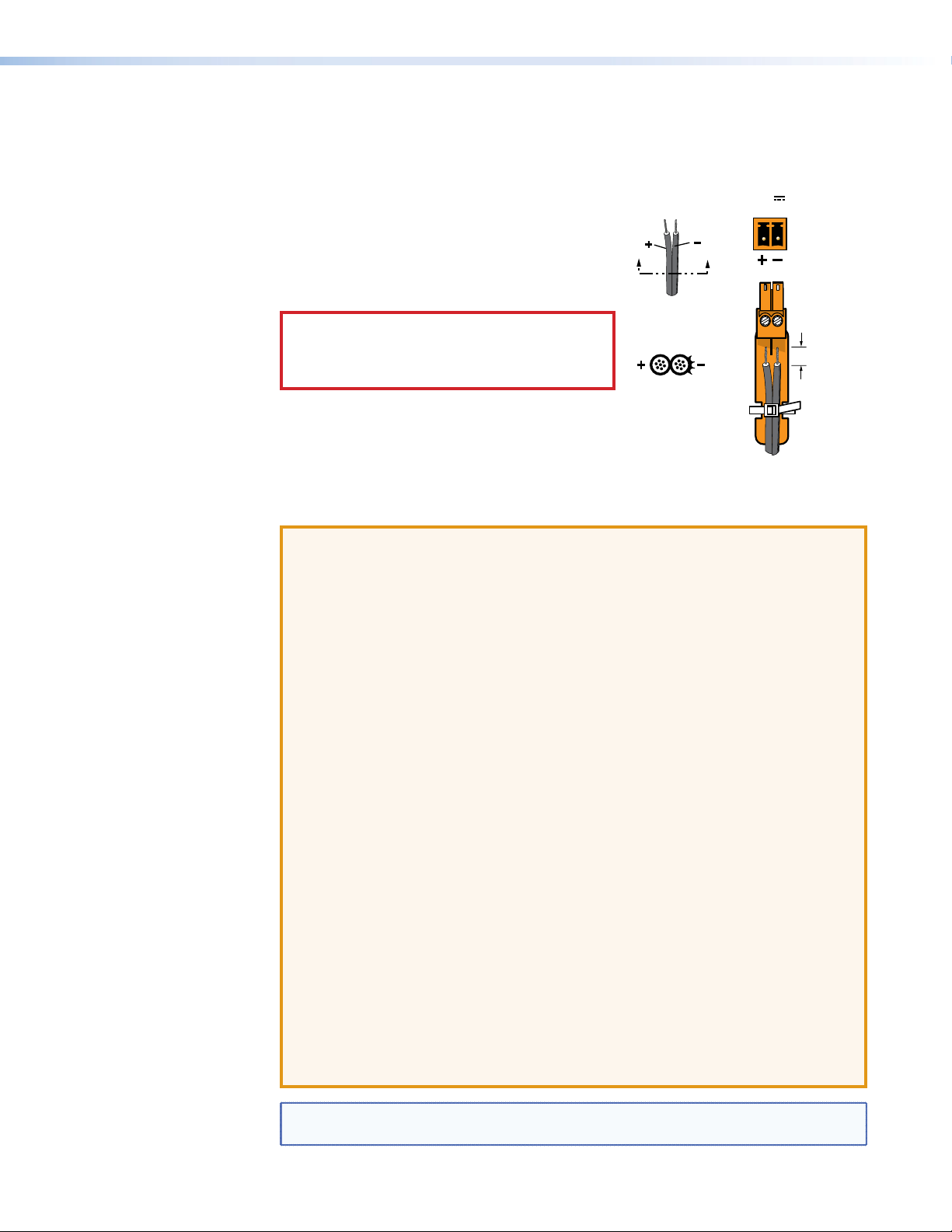
Power
The provided 12 VDC, 3 A power supply connects to
a 2‑pole, 3.5mm captive screw receptacle on the rear
panel of the encoder (see figure 6, A on page 13), or
Ridges
decoder (see figure7,A on page 13).
1. Connect the captive screw connector from the
power supply to the power receptacle.
CAUTION: Electric shock hazard — The
Power Supply
Output Cord
two power cord wires must be kept separate
while the power supply is plugged in. Remove
power before wiring.
SECTION A–A
2. Connect the AC power cord of the power supply
unit to a 110 or 220 VAC electrical source.
If it is necessary to wire the captive screw
connector, ensure the polarity of the wires is correct (see the figure to the right).
Ensure the wires are stripped correctly (see the attention and note boxes below).
ATTENTION:
• Always use a power supply provided by or specified by Extron. Use of an
unauthorized power supply voids all regulatory compliance certification and
may cause damage to the supply and the end product.
• Extron power supplies are certified to UL/CSA 60950‑1 and are classified as
LPS (Limited Power Source). Use of a non‑LPS or unlisted power supply will
void all regulatory compliance certification.
• This product is intended for use with a UL Listed power source marked
“Class2” or “LPS” and rated 12VDC, minimum 3.0 A.
• The power supply provided must only be used with a single VNM 250 device.
Never use it to power multiple devices.
• The power supply shall not be located in air handling spaces or in wall cavities.
The power supply is to be located within the same vicinity as the Extron AV
processing equipment in an ordinary location, Pollution Degree 2, secured to
the equipment rack within the dedicated closet, podium, or desk.
• The installation must always be in accordance with the applicable provisions of
National Electrical Code ANSI/NFPA 70, article 725 and the Canadian Electrical
Code part 1, section 16.
• The power supply shall not be permanently fixed to building structure or similar
structure.
• If a power strip is used, for example within rack‑mounted installations, ensure
that the current rating for the power strip and the supply is sufficient for all the
equipment within the rack.
• The length of the exposed wires in the stripping process is critical. The ideal
length is 3/16 inch (5 mm). If it is any longer, the exposed wires may touch,
causing a short circuit between them. If it is any shorter, the wires can be easily
pulled out even if tightly fastened by the captive screws.
12V
2.0 A MAX
3/16"
(5 mm) Max
NOTE: Do not tin the wires. Tinned wire does not hold its shape and can become
loose over time.
VNM 250 • Rear Panel and Connections 14
Page 21
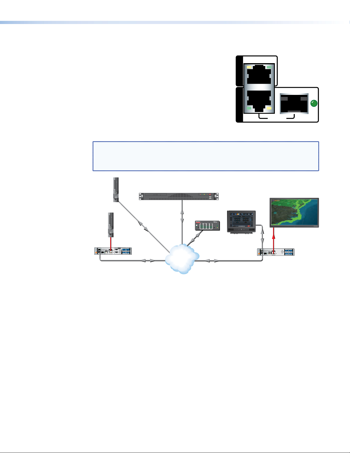
Network Connections
Contro
L
(HLI
LINK
STREAMING CONTROL
The VNM 250 series units have two separate network
connectors: one for the control network (LAN 1) and the
other for the streaming network (LAN 2). Each port has
its own IP address.
The control port (LAN 1) is not required for normal
operation. When necessary, this port may be used to
enable control by a third‑party control system.
The streaming port is the primary network connection.
All media and device communication is delivered over
this network link. To connect to the streaming network,
use either the rear panel LAN 2 RJ‑45 connector or SFP
(fiber optic) connector.
NOTE: By default, only the LAN 2 RJ‑45 connector is populated and available for use.
If an SFP connector is required, it must be purchased and installed by the user. When
installed, the SFP connector becomes the active port and the RJ‑45 connection is
inactive. Both of the LAN 2 ports share the same IP address.
l PC
ocal Control
or Web UI)
Extron
VN-Matrix Enterprise Controller
LAN 1
LAN 2
MODEL 80
ACT/
Video
Source
(PC)
HDMI
LOOP
RETURN AUDIO
AUDIO
LAN 1
POWER
12V
-A MAX
LAN 2
STREAMINGCONTROL
INPUT 2
THRU
INPUT 1
R
L
LR
RGB
USB
HDMI
GTxRxNOGIN GOUT
TxRx
RESET
ACT/
LINK
COMS
PASS THRU ALARM TTLCONTROL
LOOP THRU LOOP THRU
PC
Streaming
Ethernet
OUTPUT
I/O
Ethernet
Extron
VNE 250 Matrix
Ethernet
Switching
IP
Network
Virtual
Ethernet
IR INPUT RELAY
COM
Tx Rx
1
2
3
Extron
IPL 250
3142314231
Ethernet
®
100
LINK
ACT
42
Extron
FLAT PANEL
Flat Panel Display
Extron
TLP 710TV
POWER
12V
-A MAX
HDMI
RETURN AUDIO
LAN 1
OUTPUT
1
USB
2
ACT/
LINK
HDMI
LAN 2
STREAMINGCONTROL
AUDIO
OUTPUT
L
R
LR
TxRx
GTxRxNOGIN GOUT
RESET
I/O
COMS INPUT
PASS THRU ALARMGENLOCKCONTROL
Extron
IPL 250
R
VND 250 Matrix
Figure 8. VNM 250 Control and Streaming Network Connections
VNM 250 • Rear Panel and Connections 15
Page 22

Streaming network (LAN 2)
NOTE: The RJ‑45 and SFP streaming network connectors share the same IP address.
Only one connector can be active at any time. If the SFP cage is unpopulated, the
RJ‑45 connector is active. If the SFP cage is populated, it becomes active and the
RJ‑45 connector is inactive.
By default, the RJ‑45 port is the active streaming network connection and the SFP cage
(see figure 6,
unpopulated.
To use the RJ‑45 port (see figure 6, C on page 13 for the encoder or figure7,C on
page 13 for the decoder), connect this port to the network with a standard LAN cable.
If required, third‑party SFP connectors must be purchased separately. To install an SFP
connector, follow these points:
1. Choose a suitable SFP connector (most models are acceptable). Either singlemode
(1310 nm) or multi‑mode (850nm) modules can be used.
2. Power down the unit. In addition to being good safety practice, the unit needs to be
rebooted for the device to correctly recognize the SFP port. When a compatible SFP
module is installed, the SFP port becomes active and the RJ‑45 port is deactivated.
3. Connect a single mode or multi‑mode cable to the encoder (see figure 6, D on page
13), or decoder (see figure7,D on page 13).
on page 13 for the encoder or figure7,D on page 13 for the decoder) is
D
To use a VNM 250 device as a controller:
1. Configure the network settings of the device that is to be used as the system controller
(see Low Level Device Configuration on page 24).
2. Connect the device to the network using the streaming LAN 2 port on the rear panel of
the encoder (see figure 6, C or D on page 13), or decoder (see figure7,C or D
on page 13).
3. Open a web browser on a control PC that is connected to the same network.
4. Type in the IP address of the streaming port of the VNM 250 device that was set as
system controller in step 1, above, and use the GUI to configure the system settings
(see Setting a VNM Device as the System Controller on page 27).
NOTE: To control larger systems (ten or more components), use a VN‑Matrix
EnterpriseController (see the VN-Matrix Enterprise Controller User Guide at
www.extron.com).
Control network (LAN 1)
The control port LAN 1 may be used for system control, using the HLI control protocol. A
touchpanel or similar control interface may be connected and configured to communicate
with the VNM Enterprise Controller to recall previously configured presets.
NOTE: This control method may only be used with a VN‑Matrix Enterprise Controller.
The HLI control protocol is not supported by the VNM 250 controller (see the
VN-Matrix Enterprise Controller User Guide at www.extron.com).
VNM 250 • Rear Panel and Connections 16
Page 23
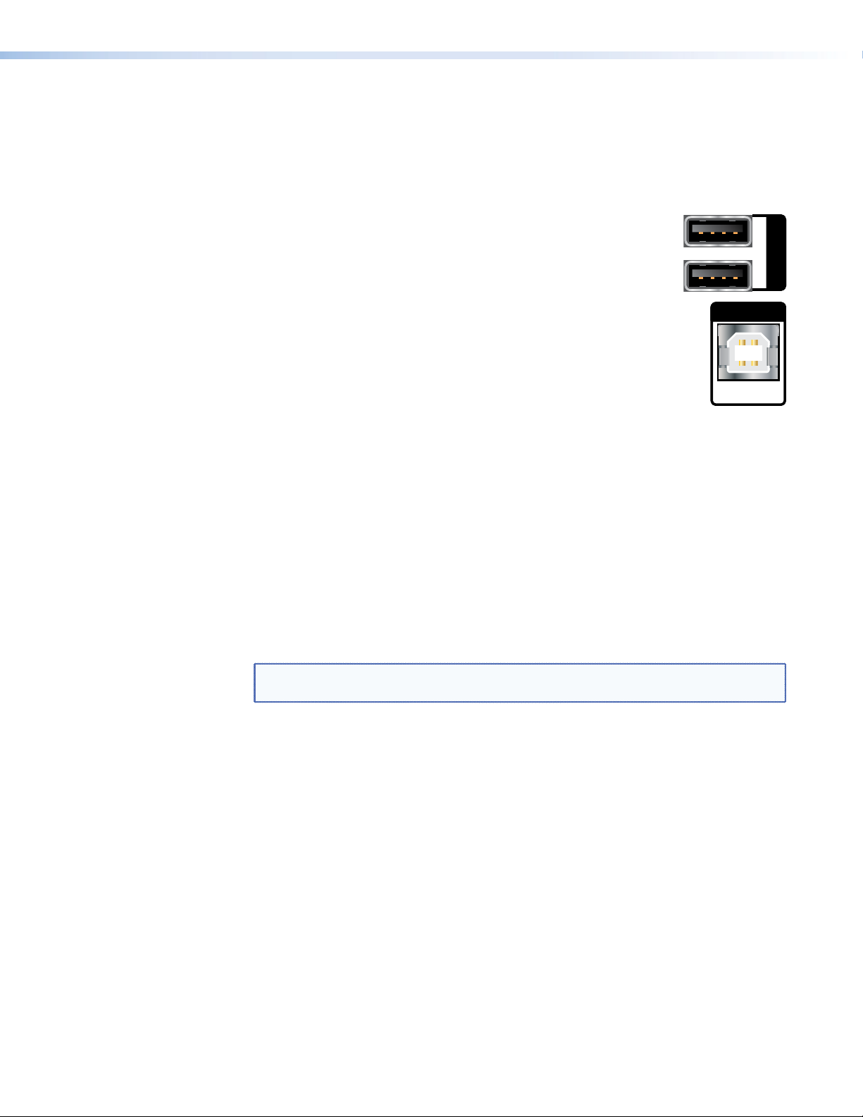
USB Ports
USB
USB
KVM function
KVM functionality permits remote collaboration between different endpoints on the network
by allowing a mouse and keyboard connected to the decoder to control a PC connected to
the encoder using the rear panel USB ports.
1. Connect a mouse and keyboard to the VND 250 rear panel USB
ports (see figure7,F on page 13).
2. Connect a PC to the VNE 250 rear panel USB port (see figure 6, E
on page 13). This connection passes the mouse and keyboard control
signals to the source PC.
3. If the system is controlled by a VNM Enterprise Controller, use the Enterprise Controller
GUI for configuring KVM functionality (see the VNM Enterprise Controller User Guide at
www.extron.com).
If a VNM 250 device is the system controller, use the GUI for that device to configure
KVM Functionality (see VNM 250 GUI Overview on page 33).
Both the encoder and decoder must be configured to allow KVM functionality, using
the Peripherals page of the web user interface of the device being used as system
controller (see Configuring KVM Functionality on page 89).
Once configured, the KVM mode is activated using a hot key sequence on the keyboard
that is connected to the decoder (see To activate a remote control session using
hot keys on page 89).
4. Configure the system so that the decoder is viewing the source PC.
NOTE: KVM is only available when there is an active video stream between the
encoder and decoder.
1
2
PC
VNM 250 • Rear Panel and Connections 17
Page 24

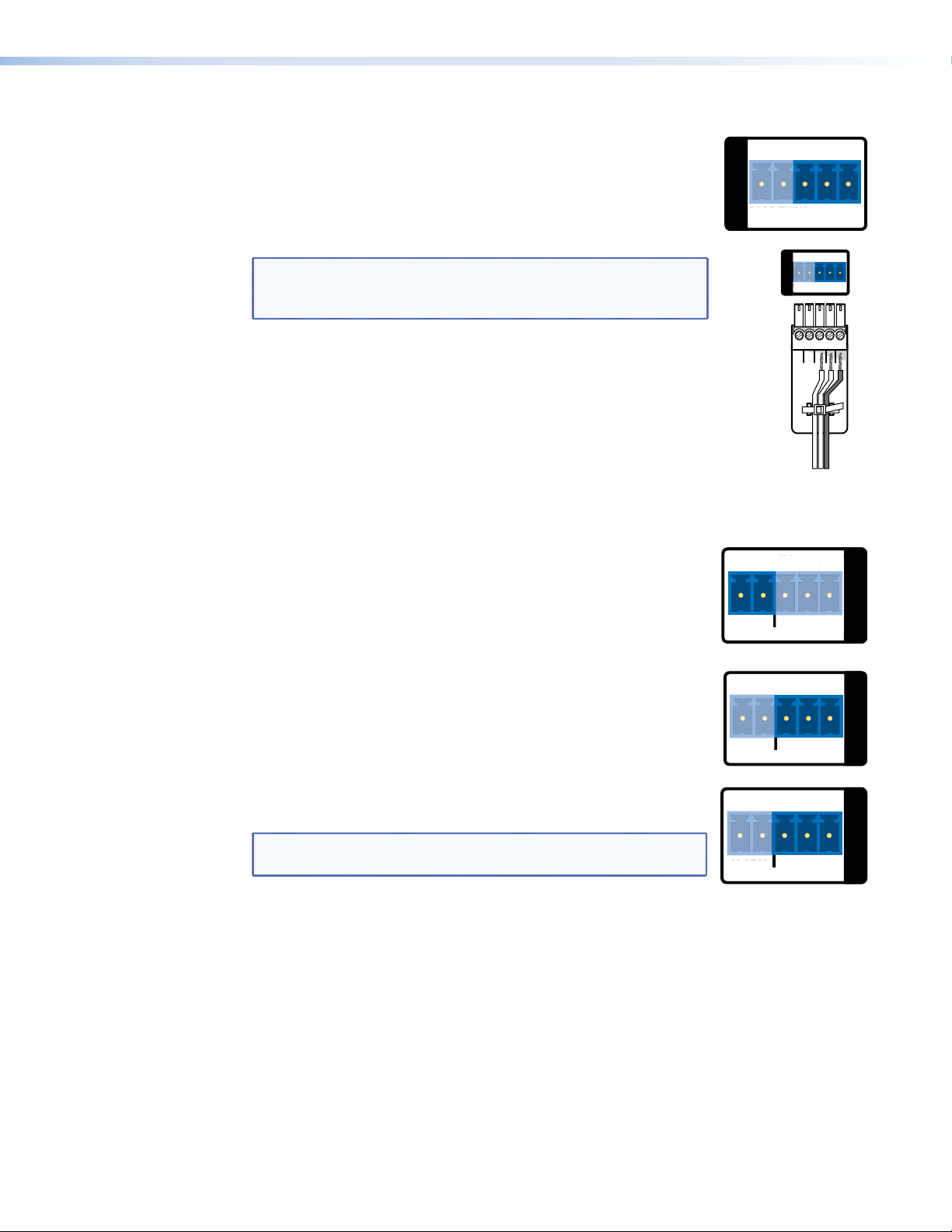
Coms
COMS
L
Tx
Rx
RS-232 pass-through
The Coms port on the rear panel of the encoder (see figure 6, R on page 13), or decoder
(see figure7,R on page 13) is used for RS‑232 pass‑through communications, allowing
a control device connected to one VNM 250 unit to control a remote device connected to a
second VNM250 unit.
Serial data received by one VNM 250 unit is transmitted over the network, using
TCP/IP, and then converted back to serial data at the target VNM 250 unit. Data flow is fully
bidirectional.
Units that are configured for this type of data flow are called pass-through groups:
z One device in each pass‑through group is designated as a server.
z One or more devices are connected as clients.
z There may be more than one pass‑through group in a system.
z A pass‑through group may consist of all encoders, all decoders, or a mixture of both.
z A device may be a server or client independently of whether it is an encoder or decoder
and independently of whether or not it is the system controller.
z Pass‑through data is not part of the media stream and cannot be stored by a
VN‑Matrixrecorder.
z Data passes through the system unchanged (transparently). No VNM 250 devices are
affected by the commands.
z The serial ports on different devices do not need to share a common baud rate.
However, if a large amount of data is sent from a high speed to a low speed data link,
some form of handshaking or flow control may be required to prevent buffer overflow on
the output device. Standard flow control methods are fully supported.
To set up the RS‑232 pass‑through group:
1. Decide which VNM 250 unit will be the server in the pass‑through group and which will
be the clients.
2. Connect your serial devices to the VNM 250 RS‑232 ports
Tx Rx
accordingly. Communication can only take place between server
and client, not between clients.
Use the first three poles of a shared captive screw connector
PASS THRU CONTROL
(Tx, Rx, and G). See the Attention and Note boxes on page 14
for information about preparing and connecting wires to a captive screw connector.
3. Log in to the web interface (see VNM 250 GUI Login on page 33).
4. Configure the server (see Pass-through Coms Server Configuration on page 90).
5. Configure one or more clients (see Pass-through Coms Client Configuration on
page 90).
GTxRx
CONTRO
VNM 250 • Rear Panel and Connections 18
Page 25
Alarms
G
IN
G
OUT
COMS
Tx
Rx
P
U
A
M
NO
G
A
O
G
RS-232 Connector
Wiring
Tx
Rx
PASS
U
P
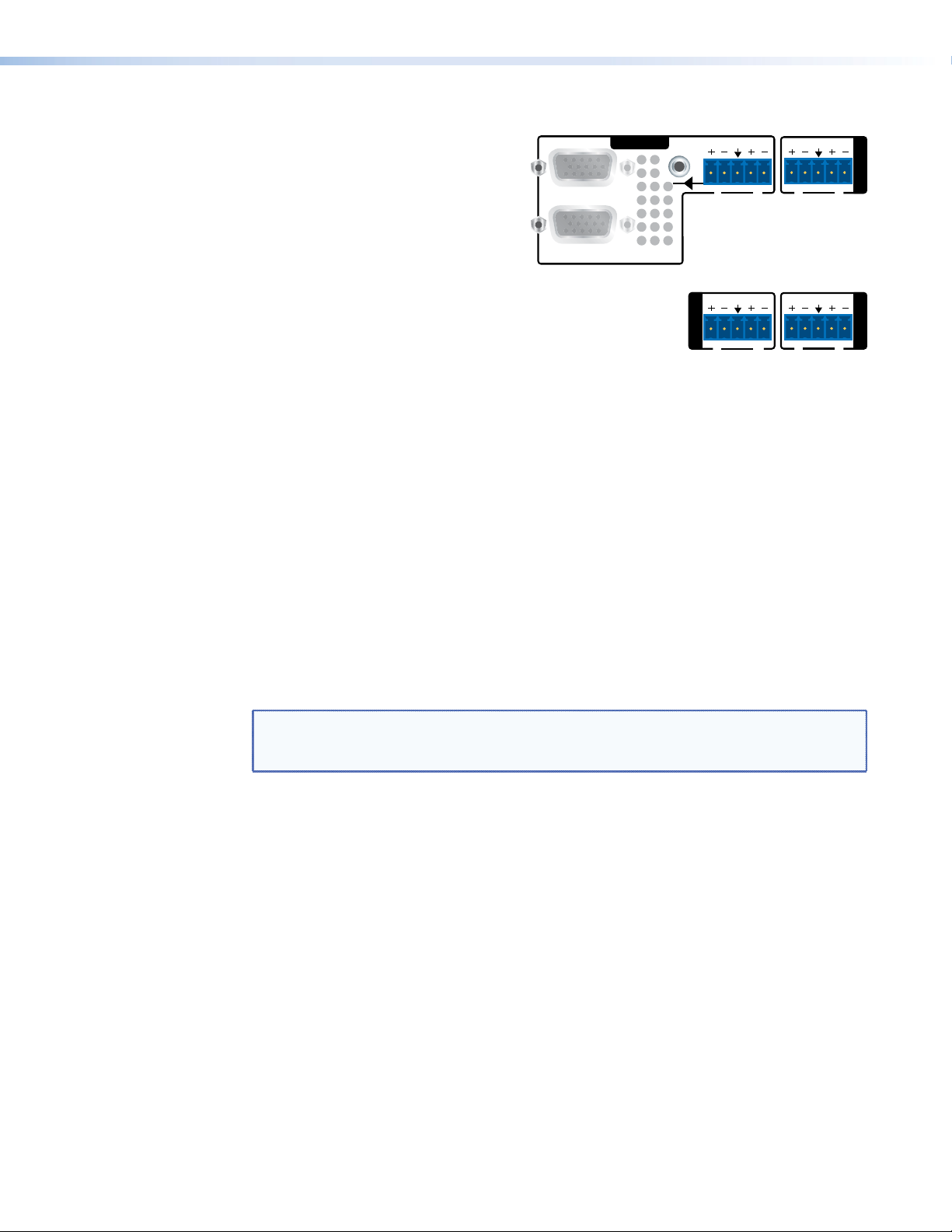
RS-232 control
RS-232 control — allows low level configuration of the encoder or
decoder. Use the three poles to the right of the shared captive screw
connector (see figure 6, R, or figure 7, R on page 13). See
the Attention and Note boxes on page 14 for information about
preparing and connecting wires to a captive screw connector. See
Low Level Device Configuration on page 24.
NOTE: The RS‑232 pins are not in the standard Extron
orientation. Ensure that the connector is correctly wired (see
the figure to the right).
Alarm relays — provide a normally open (NO) contact. Use the first
two poles of a shared captive screw connector (see figure 6, S or
figure7, S on page 13). See the Attention and Note boxes on
page 14 for information about preparing and connecting wires to a
captive screw connector.
Tx Rx
PASS THRU CONTROL
ASS THR
GTxRx
Tx Rx
GTxRx
COMS
PASS THRUCONTROL
THR
Ground
Transmit
NO GINGOUT
ALARM GENLOCK
ENLOCK
Receive
I/O
TTL
NO GINGOUT
TTL (VNE 250) —the TTL (Transistor‑transistor logic) feature is not
currently supported.
ALARM TTL
LAR
I/O
Genlock
Genlock I/O (VND 250) —is used to synchronize the video output
on multiple decoders.
NOTE: The VND 250 uses TTL level signalling, which is not
compatible with normal genlock sources.
One decoder is selected as the reference (master) unit, and provides the signal that is used
to synchronize all the other units (slaves).
1. Configure one decoder as the Master unit, using the web‑based GUI control program
(see Genlock on page59).
2. Configure all the other decoders as slaves by selecting the Genlock check box of the
web‑based GUI control program (see page 59).
3. Connect the Ground connector of the master unit to the ground connector of the first
slave device.
4. Connect the Out connector of the master unit to the In connector of the first slave
device.
NO GINGOUT
N
ALARM GENLOCK
LARM
I/O
VNM 250 • Rear Panel and Connections 19
Page 26
5. Connect the ground connector of the first slave device to the ground connector of the
INPUT 2
THRU
O
INPUT 1
second slave device.
6. Connect the genlock out from the first slave device to the genlock in of the second
slave device.
7. Repeat steps 5 and 6 to link as many slave devices as required.
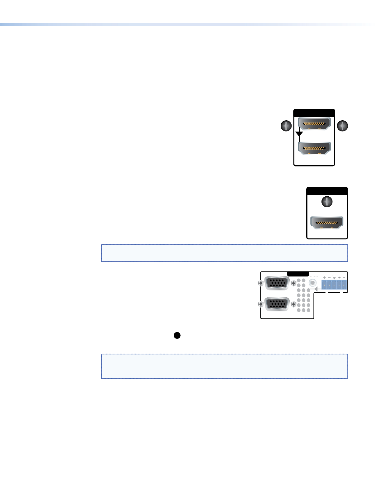
Video Connections
HDMI input (VNE 250) — connect an HDMI digital video source
to this port (see figure 6, G on page 13). For a list of supported
modes, see the Specifications on the VNM 250 web page at
www.extron.com.
HDMI loop-through (VNE 250) — provides fully buffered
output of all data from the HDMI input source. Connect a local
HDMI monitor to this port (see figure 6, H on page 13).
HDMI
LOOP THRU
HDMI output (VND 250) — connect an HDMI digital video display to this
OUTPUT
port (see figure7,I on page 13).
Use the provided LockIt HDMI Cable Lacing Brackets to secure the
HDMI cables to the VND 250 (one screw above the port) or VNE 250
(two screws to the sides of the port). Follow the instructions on the card
provided with the brackets. This card is also available at
www.extron.com.
HDMI
NOTE: A full‑screen green image is displayed when a non‑HDCP compliant display is
used in conjunction with HDCP‑encrypted content.
LOOP
Analog video input (VNE 250) — connect an analog
video source to the 15‑pin HD connector labelled "RGB"
(see figure 6,
modes, see the Specifications on the VNM 250 web
on page 13). For a list of supported
K
RGB
LOOP
THRU
AUDIO
AUDI
L R
page at www.extron.com.
Analog video loop-through (VNE 250) — provides
LOOP THRU
fully buffered output of all data from the analog video
input source. Connect a local analog video monitor to the 15‑pin HD connector labelled
"Loop Thru" (see figure6,L on page13).
A list of Supported EDID Modes can be found on page 122.
NOTE: Both loop‑through outputs will display the image from the input that has
been selected for streaming. HDCP‑encrypted content is only shown on compliant
displays.
VNM 250 • Rear Panel and Connections 20
Page 27
Audio Connections
G
INPUT 2
OUTPUT
LR
OUTPUT
VND 250
Audio loop-through (VNE 250) —
connect a 3.5 mm TRS jack to this
socket for unbalanced buffered output
from the audio input source (see
figure6,M on page13).
Analog program audio input
(VNE 250) — connect balanced or
unbalanced, mono or stereo audio
to this 5‑pole, 3.5 mm captive screw
receptacle (see figure6,N on
page13).
Return audio input (VND 250) —
allows bidirectional communication,
using a reverse audio signal sent from a decoder to the associated encoder. Connect
balanced or unbalanced, mono or stereo audio input to this 5‑pole, 3.5 mm captive screw
connector (see figure7,O on page 13).
Return audio output (VNE 250) — allows bidirectional communication by sending a
reverse audio signal from an associated decoder, to be played by the encoder. Connect the
audio output from this 5‑pole captive screw connector to an amplifier or powered speakers
(see figure6,P on page13).
Analog program audio output (VND 250) — connect the audio output from this
5‑pole captive screw connector to an amplifier or powered speakers (see figure7,Q on
page13).
B
R
LOOP THRU
VNE 250
LOOP
THRU
AUDIO
L R
RETURN AUDIO
INPUT
LR
RETURN AUDIO
L R
AUDIO
Reset
Reset button — is used to reboot the operating system. To activate this recessed button,
insert the blade of a small screwdriver or a similar device into the hole and press the button
(see figure6,J or figure7,J on page13)..
NOTE: The reset button simply reboots the system. It does not alter any settings.
To reset IP addresses, use the Reset option on the front panel menu (see encoder
Reset on page99 or decoder Reset on page 109).
VNM 250 • Rear Panel and Connections 21
Page 28
System
Configuration with
the Enterprise
Controller
All Matrix systems require one device that acts as the system controller. For a small system
(ten devices or fewer), this can be either a VNE 250 or VND 250. For larger systems a
VN‑Matrix Enterprise Controller must be used.
A system controlled by the Enterprise Controller can incorporate any VN‑Matrix devices,
including recorders, into the system.
Systems controlled by a VNM 250 device cannot exceed 10 devices in total. A VNM250
controller supports VNM 250 encoders and decoders and PCs running the VNS104
software. It does not support recorders. If an incompatible VN‑Matrix device is added to a
system controlled by a VNM250 device, the controller cannot detect or control that device.
Controlling Your System with a VN-Matrix Enterprise Controller
1. Connect a PC and a VN‑Matrix Enterprise Controller to the same network as the
components of your streaming AV system.
NOTE: The PC and Enterprise Controller must be connected to the same network
as the streaming port (LAN 2) of the VNM 250 device.
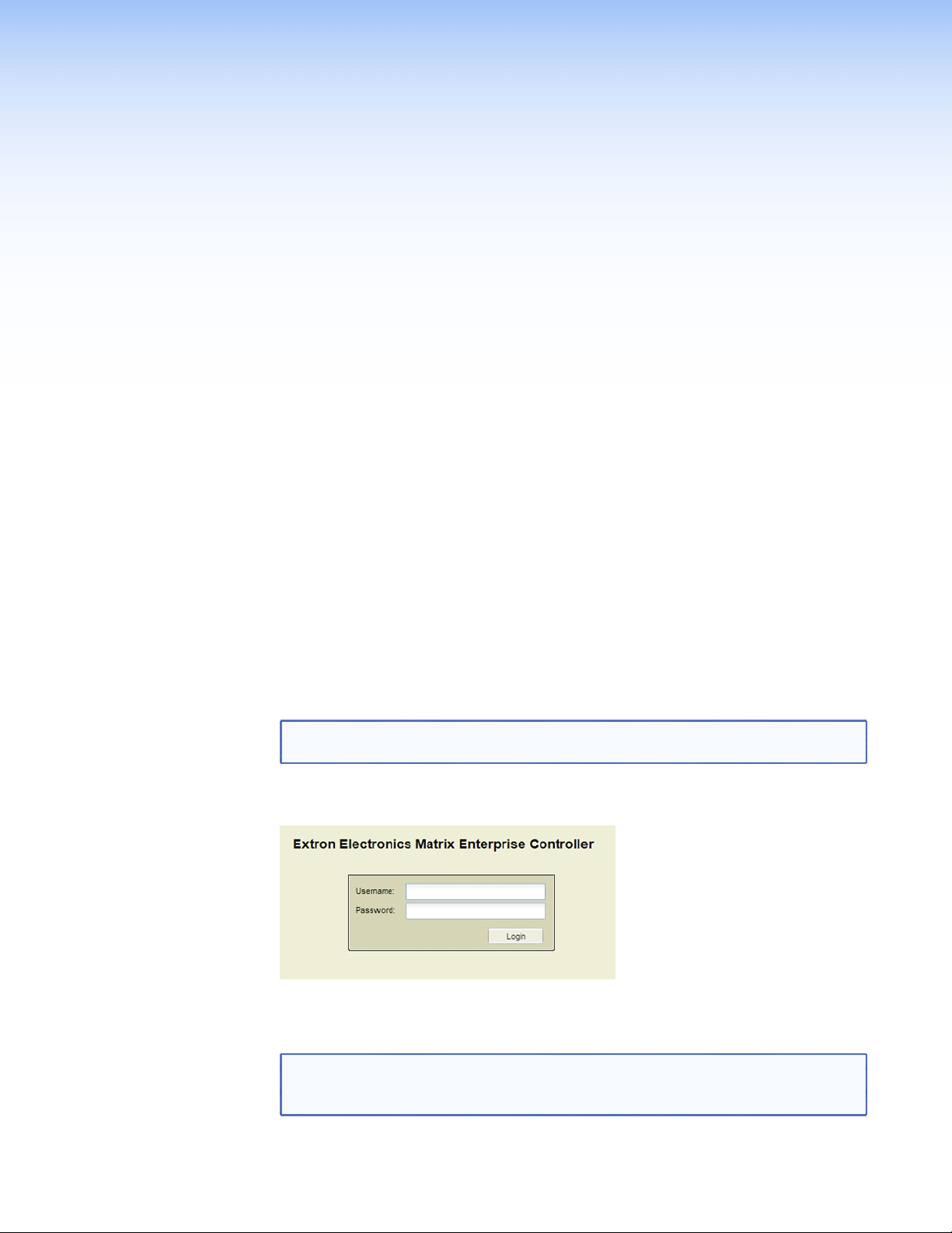
2. Open an internet browser on the PC and enter the IP address of the VNM Enterprise
Controller in the address bar. The login screen opens.
Figure 9. VN-Matrix Enterprise Controller Login Page
3. Enter the Username and password.
NOTE: Check with your Network Administrator for the Username and password. If
they have not been changed from the default settings, the Username is admin (all
lower case) and there is no password (leave the box empty).
VNM 250 • System Configuration with VNM Enterprise Controller 2222
Page 29
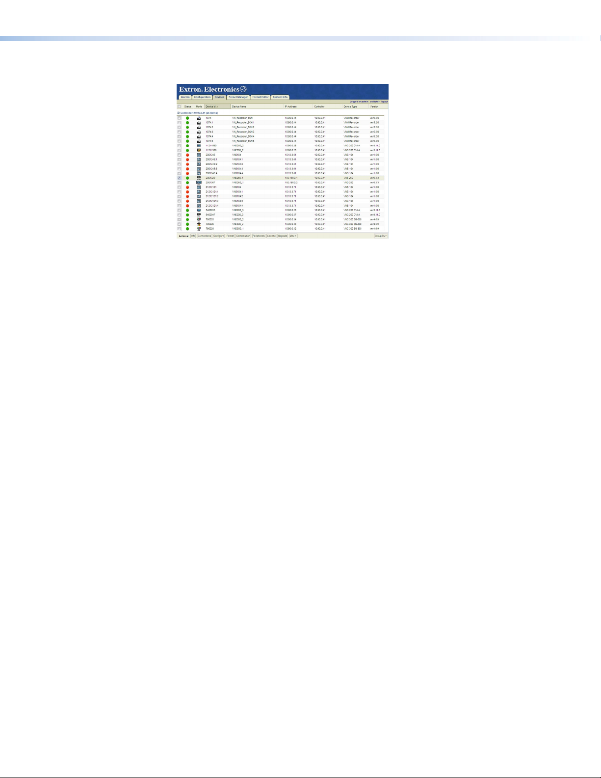
The Enterprise Controller GUI opens.
Figure 10. VN-Matrix Enterprise Controller Device List
4. To configure the system with the Enterprise Controller, see the VN-Matrix Enterprise
Controller User Guide, which is available at www.extron.com.
VNM 250 • System Configuration with VNM Enterprise Controller 23
Page 30

Low Level Device
Control Network port
Streaming Network port
10. Speed/Duplex: auto_10_100_1000
Please select an option
Configuration
The RS‑232 control port is used to configure the network settings for the VNE 250 and the
VND 250. Follow these instructions:
1. Use an RS‑232 cable to connect a control PC to the rear panel Coms port of the
VNM 250 device (see page 19).
2. On the PC or laptop, open a terminal emulation program, such as Extron DataViewer,
with the following settings:
z Baud rate: 115200
z Data bits: 8
z Parity: None
z Stop bits: 1
z Flow control: None
NOTE: DataViewer can be downloaded, free of charge, from the Extron website
(www.extron.com).
3. Enter the
User name and Password.
NOTES:
• When DataViewer first opens, it may be necessary to press <Enter> for the
User name prompt to appear.
• By default, the User name is config and the Password is also config.
The low level configuration menu opens (figure 11 shows default values):
====================
0. Speed/Duplex: auto_10_100_1000
1. IP Prov mode: static [dhcp]
2. address: 192.168.253.254
3. netmask: 255.255.255.0
6. mtu: 1500
7. VLAN ID: 0
8. controller ip: 192.168.254.254
9. Exit
:
======================
11. IP Prov mode: static [dhcp]
12. address: 192.168.254.254
13. netmask: 255.255.255.0
14. gateway: 192.168.254.1
16. mtu: 1500
17. VLAN ID: 0
18. Controller port: 5432
19. webserver port: 80
Figure 11. Low Level Configuration Menu Page 1
NOTE: These values are held in local memory on the unit itself.
VNM 250 • Low Level Device Configuration 2424
Page 31

4. At the Please select an option: prompt, type the number of the parameter you wish
to change followed by <Enter>:
a
z 0
or 10b — these options set the network link speed. When you choose either
option, you are offered a further choice:
1. auto_10_100_1000 — configures for auto speed negotiation up to 1 Gbps.
2. auto_10_100 — configures for auto speed negotiation up to 100 Mbps.
Enter 1 or 2 followed by <Enter> at the prompt. The default setting is
1. auto_10_100_1000.
NOTE: A Gigabit network is recommended for streaming media applications.
a
z 1
or 11b — these options determine whether the IP address of the unit will be static
or set by DHCP. When you choose either option, type static or dhcp followed by
<Enter>. The default setting is static.
NOTES:
• static and dhcp are all lower case letters.
• When 1 is set to dhcp, options 2 and 3 are not available. When 11 is set
to dhcp, options 12‑14 are not available.
a
z 2
and 12b — these options set the local address of the network port. Standard
rules for IP addresses apply. The default values are 192.168.253.254 (control
network) and 192.168.254.254 (streaming network).
Do not use leading zeros. For example, 192.168.10.25 is valid; 192.168.010.025
is not valid.
NOTE: The control and streaming ports must be assigned to different subnets.
a
z 3
and 13b — these options set the network Subnet Mask. The default value is
255.255.255.0. Standard rules for IP Addresses apply. Do not use leading zeros.
b
z 14
— this option sets the IP address for the default gateway. The default value is
192.168.254.1.
This value is required for systems with multiple subnets. The Default Gateway must
be on the same subnet as the streaming port.
To clear a Gateway Address, select 14 and press <Enter> with no value set.
z Options 4, 5, and 15 are not available.
a
z 6
and 16b — these options set the Maximum Transmission Unit (MTU) Setting. The
default value is 1500.
This value affects the system performance. Larger values may cause packets to
be fragmented (split) and smaller values may not make efficient use of the network
capacity.
a
z 7
and 17b — these options set the VLAN ID. The VLAN ID may be set on each of
the network ports. The default value is 0.
NOTES:
a
Options 0 to 6 relate to the control network LAN 1. For full information about
Configuring the Control Port, see page 32.
b
Options 10 to 16 relate to the streaming network LAN 2 (RJ‑45 or SFP).
VNM 250 • Low Level Device Configuration 25
Page 32

z 8 — this option sets the IP address of the system controller. The controller IP
6. DHCPD/SLAAC server enable: dhcp
7. DHCP IP range: 192.168.254.200 192.168.254.254
9. Exit
Please select an option
address must be set to the IP Address of the streaming port on the unit designated
as controller. This is the network port over which system control data is sent. The
default value is 192.168.254.254.
z 18 — this option sets the number of the port that is used for communications with
the system controller. The default value is 5432 but it may be changed, if required.
All units in the system must have the same port number assigned.
z 19 — this option sets the number of the port that communicates with the web
server. The default value is 80 but it may be changed, if required. The web browser
in use must use the same port number.
NOTE: Option 19 is only available when the device is configured as the system
controller.
z 9 — this option allows you to exit the network port configuration page and opens
the Controller and DHCP Configuration page. Any changes that have been made
are activated only after exiting the Controller and DHCP Configuration page and
rebooting.
5. Select 9 followed by <Enter>.
The DHCP configuration settings page opens:
:
Figure 12. Low Level Configuration Menu Page
NOTE: The settings in this menu apply only when the device is configured as the
system controller.
6. At the
Please select an option: prompt, type the number of the parameter you wish
to change followed by <Enter>:
z 6 — this option enables or disables the DHCP/SLAAC server. To enable the server,
enter dhcp followed by <Enter>. To disable the server, enter none followed by
<Enter>.
NOTE: dhcp and none are all lower case letters.
z 7 — this option sets the DHCP IP range and is only available when DHCP is
enabled (option 6). Enter the DHCP pool address range in the following format:
xxx.xxx.xxx.xxx<space>xxx.xxx.xxx.xxx
where the lower IP address value and the upper IP address value are separated by
a single space.
z 9 — this option saves all changes, closes the Controller and DHCP config page,
and automatically reboots the device in the config login.
7. Select 9 followed by <Enter>.
The Controller and DHCP configuration settings page closes and the device
automatically reboots to the config login screen. The changes that were made in steps
4‑6 are implemented.
VNM 250 • Low Level Device Configuration 26
Page 33

Setting a VNM 250 Device as the System Controller
All Matrix systems require one device that acts as the system controller. For small systems
(ten devices or fewer), this can be either a VNE250 or VND250. For larger systems, a
VN‑Matrix Enterprise Controller must be used.
The VNM250 device that is chosen as the system controller must use static IP address
settings.
Extron recommends using Low Level Device Configuration (see page 24) to set one
device as the system controller.
Configuring the System Controller with a Static IP Address
To configure the system controller with a static IP address:
1. Open the configuration menu of each device (see page 24) and ensure that the
Streaming Network port IP Prov mode (option 11) is set to static.
2. Set the IP address (option 12), netmask (option 13), and gateway (option 14) for the
streaming network (LAN 2).
3. Set the Controller IP address (option 8) to the same address as the streaming port.
4. Use option 9 to exit from the configuration menu.
Configuring Other VNM 250 Devices with a Static IP Address
To configure the system with static IP addresses for all devices:
1. Open the configuration menu (see page 24) and ensure that the Streaming Network
port IP Prov mode (option 11) is set to static.
2. Set the IP address (option 12), netmask (option 13), and gateway (option 14) for the
streaming network (LAN 2).
3. Set the Controller IP address (option 8).
NOTES:
• Every device must have a unique Streaming network port (LAN 2) IP address
4. Use option 9 to exit from the configuration menu.
5. Use option 9 to exit from the Controller and DHCP menu.
6. Repeat steps 1‑5 to configure all other VNM 250 devices in the system.
(option12).
• Every device in the system must have the same Controller IP address
(option8) and this must be the same as the streaming network port (LAN 2)
IP address on the device selected to be system controller.
VNM 250 • Low Level Device Configuration 27
Page 34

Configuring a VNM 250 Series Unit for DHCP
Control Network port
Streaming Network port
10. Speed/Duplex: auto_10_100_1000
Please select an option:
VNM250 devices may have their streaming port network settings configured using IP
addresses from a DHCP server.
For small systems, the VNM250 device that is used as the system controller may also be
configured to act as a DHCP server. It is then used to set the streaming port parameters
of the other VNM250 devices in the same system. For larger systems a Windows DHCP
server may be used.
NOTE: The VN Matrix Enterprise Controller does not support DHCP server
functionality.
Configuring a VNM 250 System Controller as a DHCP Server
The following requirements must be observed:
z The DHCP server will run only on a VNM250 device that is configured as the system
controller.
z The streaming network settings of the controller device must be statically assigned.
z The Controller IP address must be statically assigned.
To configure the VNM 250 system controller as a DHCP Server:
1. Connect a control PC to the chosen unit and log in as described in steps 1-3 on
page24.
====================
0. Speed/Duplex: auto_10_100_1000
1. IP Prov mode: static
2. address: 192.168.253.254
3. netmask: 255.255.255.0
6. mtu: 1500
7. VLAN ID: 0
8. controller ip: 192.168.254.254
9. Exit
9
======================
11. IP Prov mode: static
12. address: 192.168.254.254
13. netmask: 255.255.255.255
14. gateway: 192.168.254.254
16. mtu: 1500
17. VLAN ID: 0
18. Controller port: 5432
19. webserver port: 80
Figure 13. Configuring a VNM 250 Series Unit as a DHCP Server.
2. Set IP Prov mode (option 11) to static.
3. Ensure that option 12 has a valid IP address. This address must be in the same range
that the user wishes to allocate when DHCP is enabled.
4. Ensure that option 13 has a valid subnet mask.
5. Ensure that option 14 has a valid gateway.
NOTE: If the gateway is invalid or not present, the unit will not be able to act as a
DHCP server.
6. Ensure that option
8 (controller address) is set to the same address as set in option 12.
VNM 250 • Low Level Device Configuration 28
Page 35

7. Select option 9 to move to the controller section of the menu.
6. DHCPD/SLAAC server enable: none
9. Exit
Please select an option:
6. DHCPD/SLAAC server enable: dhcp
7. DHCP IP range: 192.168.254.200 192.168.254.254
9. Exit
Please select an option:
Control Network port
Streaming Network port
10. Speed/Duplex: auto_10_100_1000
Please select an option:
Figure 14. Low Level Configuration Menu, Page 2
8. Select option 6 and enter dhcp. This enables the DHCP server in the device.
9. Once option 6 is set to dhcp, option 7 becomes visible. Select option 7 and enter the
range of addresses that the DHCP server will use when allocating addresses. This range
must include the address set for option 12 on the previous page.
Figure 15. Controller Set as a DHCP Server
10. Select option 9 to commit the settings and reboot the unit.
Configuring a VNM 250 Series Unit to Operate with a DHCP Server
1. Login to the chosen unit using a serial cable and enter the user name of config with
the password of config.
2. Select option 11 from the menu and enter the value dhcp.
3. Press <Enter>. Options 12, 13 and 14 disappear from the menu. These values are
assigned when the unit contacts the DHCP server and acquires a valid IP address.
4. Select option 8 (controller address). Enter either the IP address of the system controller
or set the IP address to “0.0.0.0”. Either method is acceptable.
If the address is set to “0.0.0.0” the DHCP server must either be a VNM 250 unit or
a DHCP server that has the “Vendor Specific Option” correctly configured. This is
explained in the next section.
====================
0. Speed/Duplex: auto_10_100_1000
1. IP Prov mode: static
2. address: 192.168.253.254
3. netmask: 255.255.255.0
6. mtu: 1500
7. VLAN ID: 0
8. controller ip: 0.0.0.0
9. Exit
Figure 16. Configuring a VNM 250 Series Unit to Operate with a DHCP Server
9
======================
11. IP Prov mode: dhcp
16. mtu: 1500
17. VLAN ID: 0
18. Controller port: 5432
VNM 250 • Low Level Device Configuration 29
Page 36

5. Select option 9 (Exit) to enter the Controller menu.
6. DHCPD/SLAAC server enable: none
9. Exit
Please select an option:
Figure 17. Low Level Configuration Menu, Page 2
Ensure that options 6 is set to none.
6. Select option 9 (Exit) to reboot the device.
The streaming network settings will be configured when the VNM250 device is
connected to a network with a properly configured system controller or DHCP server.
NOTE: The VN‑Matrix Enterprise Controller does not currently provide DHCP
server functionality.
Using a Dedicated DHCP Server
If required, a dedicated DHCP server may be used to provide the IP address settings for the
VNM250 device in a system.
The device that is acting as the system controller must have its IP settings configured
statically.
The other VNM250 devices in the system are to be configured for DHCP as described in
Configuring a VNM 250 Series Unit to Operate with a DHCP Server on the previous
page.
If possible, the DHCP server should be configured to provide the Controller IP address and
port number, using the Vendor Specific Option. Otherwise, the IP address of the system
controller must be entered on all VNM250 devices in the system.
VNM 250 • Low Level Device Configuration 30
Page 37

Configuring a Windows 2008 R2.
The windows DHCP server can be configured so that, when a VNM 250 device contacts the
server for an IP address, the server can include the IP address of the system controller and
the controller port number as part of the DHCP configuration.
The figure below shows a Windows Server 2008 R2 installation. Other operating systems
may vary.
Scope Options ?
General
Advanced
Available Options
043 Vendor Specic Info Embedded w
044 WINS/NBNS Servers
045 NetBIOS over TCP/IP NBDD
046 WINS/NBT Node Type
Data entry
String value:
controller-ip=192.168.254.254;controller-port=5432
OK Cancel
Description
NBNS Addre
NetBIOS ov
0x1 = B-nod
Apply
Apply
Figure 18. Scope Options Window
1. Open the Server Manager.
2. Highlight the scope options and right click. Select
Configure Options from the
pop‑up.
3. In the General tab, navigate to option 043 Vendor Specific Info and select the
check box.
4. In the Data Entry text box, enter:
controller-ip=xxx.xxx.xxx.xxx;controller-port=xxxx;
where xxx.xxx.xxx.xxx is the IP address of the controller and “xxxx” is the port
number used by the VNM 250 system for controller communication. By default, this
value is 5432.
VNM 250 • Low Level Device Configuration 31
Page 38

Control Port
The control port is used to access the web UI or the HLI control interfaces on a VN‑Matrix
system.
The web UI on either a VNM250 device (configured as the system controller) or a
VNMEnterprise controller may be accessed from any device on the same system by
connecting a PC to a properly configured control port. This may be useful when a system is
undergoing commissioning, but is not required for normal operation.
If a VNMEnterprise controller is in use, then the HLI control interface may also be accessed
from the control port of any VNM250 device on the same system. This facilitates the
connection of an external control system, where necessary.
The web UI and HLI interface are both accessed at the control port via a connection across
the streaming network. A process similar to Network Address Translation (NAT) is used to
map data received on the control port so that it is transferred to the system controller using
the streaming network. Replies from the system controller to the local device follow the
reverse path.
z From a web browser enter http://[system controller IP address] to access the
system Controller web UI.
z To access the HLI interface on a VNM Enterprise Controller, then the IP address of the
system controller is used along with the appropriate port number. For the HLI control
protocol the port number is 9996.
NOTE: The user will NOT be able to directly access devices that are connected to the
control ports of other VNM 250 devices.
Configuring the Control Port
Configure the control port by using the process described in the Low level Configuration
section that starts on page 24.
When configuring the Control port the following must be observed:
z The IP addresses assigned to the Control Port and the Streaming Port must not be on
the same subnet.
z Give the user PC a default gateway that forces IP messages to be passed to the system
controller via the control port interface. For a directly connected PC, set the default
gateway of the PC (or control system) to the IP address of the VNM250 control port.
VNM 250 • Low Level Device Configuration 32
Page 39

VNM 250 GUI Overview
VNM 250 GUI Login
The system can be configured and controlled using a graphical user interface (GUI), which is
served by the VNM 250 device that is acting as the system controller. To use this GUI, follow
these instructions:
1. Use one of the following web browsers with the version shown or later:
z Windows
z Mozilla
z Google
The PC must be on the same network as the VNM 250 controller.
2. Enter the controller IP address in the search bar. Press <Enter>.
3. The VN‑Matrix Controller login page opens:
®
Internet Explorer® version 8
®
Firefox® version 20
®
Chrome™ version 30
Figure 19. VN-Matrix Controller Login Page
4. Enter the Username and Password. By default, these are both admin (all lower case).
5. Press Log In. The VNM 250 GUI opens at the Device List tab (see page 35).
VNM 250 • VNM 250 GUI Overview 3333
Page 40

VNM 250 GUI Tabs
The following list shows the tabs that are available in the VNM 250 GUI control program and
provides links to more detailed descriptions of each tab. They are divided into Shared tabs
(encoder and decoder), Encoder tabs, and Decoder tabs.
Configuration of the system, using the control program is described in Configuration with
the VNM 250 GUI (see page 66).
Tabs Shared by Both the Encoder and Decoder
z Device List (see page 35)
z Accounts (see page 36)
z Alarms (see page 37)
z Alarms Logs (see page 38)
z Upgrade (see page 40)
z Peripherals (see page 41)
z License (see page 44)
Encoder tabs
z Encoder Device (see page 45)
z Configure (VideoPort0) (see page 46)
z Bandwidth (see page 48)
z Video Setup (see page 52)
z Configure (AudioPort0) (see page 53)
z Configure (data) (see page 55)
Decoder tabs
z Decoder Device (see page 57)
z Display (Display0) (see page 58)
z Bandwidth (video) (see page 61)
z Bandwidth (audio) (see page 62)
z Bandwidth (data) (see page 64)
z Format (see page 65)
VNM 250 • VNM 250 GUI Overview 34
Page 41

Tabs Shared by Both the Encoder and Decoder
Some of the tabs listed in this section, for example the Device List (see below), Accounts
(see page 36), Alarms (see page 37), and Alarm Logs tabs (see page 38), can be
accessed without first selecting a device.
Other tabs, for example the License (see page 44), Upgrade (see page 40), and
Peripherals (see page 41) tabs, can only be selected once a device has been selected.
However, the options in these tabs are identical whether you navigate to the page from an
encoder or a decoder. Therefore, they have also been included in this Shared Tabs section.
Save All, Help, and Logout are available in all screens, although these function as buttons
rather than tabs.
Save All saves changes you have made:
On the Device List page, Save All saves all changes on the system.
On the Device page, Save All saves only the changes to that device.
Help provides a context‑sensitive help page that explains the features of the tab that is
currently open.
Logout, logs you out of the system.
Device list tab
The control program opens to the Device List tab.
Figure 20. VN-Matrix Device List Tab.
When the Device List tab is selected, the Accounts and Alarms tabs become available.
The Device List lists all the devices in the system, using the following icons:
Mode Icon Description Status Icon Description
Unknown device Alarm status gray — a device that has not
contacted the controller during this session.
Encoder device
(source)
Decoder device
(display)
Alarm status green — a device under active
control with no alarms.
Alarm status yellow — a device under active
control showing only Warning alarms.
Alarm status red — a device under active
control showing Critical alarms.
VNM 250 • VNM 250 GUI Overview 35
Page 42

Click on any of the text or icons for a specific device to open the Device tab for that device.
For information about the encoder device tab, see page 45. For information about the
decoder device tab, see page 57.
Accounts tab — controller configuration
From the Device List tab, click the Accounts tab:
Figure 21. Accounts Tab
The Accounts screen is used to change the passwords of the public and admin accounts,
to update the system clock time, and to enter controller license details.
Password Management
The admin account allows full access to the VNM 250 web GUI. The public account allows
read‑only access.
The admin and public user names cannot be modified.
By default the password for the admin account is admin. The password for the public
account is public.
The admin account password can only be modified when you are already logged in as
admin. If you are logged in as public, the admin password modification fields are disabled.
To change the password, enter the Current Password, the New Password, repeat the new
password in the Confirm box then press Update Passwords.
NOTES:
• The password should consist of letters, numbers and the underscore character.
Case is significant.
• Some changes must be implemented by pressing the update button. Where
changes are pending both the changed item and the update button will be shown
in yellow.
VNM 250 • VNM 250 GUI Overview 36
Page 43

Clock Management
NOTE: The Current Time is the date and time when the page was served.
The Current Time is used by all devices to time stamp system events and alarms. The clock
setting on all VNM 250 devices is factory set to UTC time and it is not necessary to make
any changes to the setting for the system to operate. The clock setting may be changed to
set the controller to local time, if required.
New Time is the updated date and time. It can only be modified by the admin user
and should be input in an identical format to the Current Time: year-month-date
hours-minutes-seconds
z The year should include the century, eg: 2005.
z The month is a number from 1 to 12
z The date is a number from 1 to 31
z Hours is a 24 hours clock number from 0 to 23
z Minutes and seconds are numbers from 0 to 59
.
The time is updated by pressing Change Time.
Controller Licensing Management
The Controller licensing is used to enable the use of VNS 104 and VNM Software decoders
on a system. The Controller license contains two elements, an option and a checksum. New
licenses may be obtained from your Extron dealer when they are required. Talk to the Extron
S3 Technical Support (for contact information see the last page of this user guide).
Click on the Change Licence button to open the License tab.
Alarms tab
From the Device List tab, click the Alarms tab:
Figure 22. Alarms Tab
The Alarms screen is used to monitor the active alarms on the system and to modify the
severity and reporting attributes of alarms on a device by device basis.
Alarms are descriptions of problem events with the system. They are raised and cleared
by hardware and typically have a 5 second hysteresis — once an alarm is raised, it stays
on for 5 seconds even though the error event has cleared. This prevents noisy conditions
saturating the alarm log buffer.
VNM 250 • VNM 250 GUI Overview 37
Page 44

Alarms can have three degrees of severity indicated by the alarm icons in the device list and
the alarm status messages at the top of each page:
z Critical is shown in red and usually means the service has failed. If the device has a
critical alarm it illuminates the red LED on the front panel and activates the closure relay
accessed by the rear panel connector.
z Warning is shown in amber and indicates a less severe error has occured. Often a
Warning is raised when there is an expectation that another Critical alarm shows the
root‑cause of the problem.
z Setting the severity to None effectively filters this alarm ‑ it still appears in the alarms list
but does not affect the colored indicators.
Alarms can also be Reporting or Not-Reporting. A Reporting alarm will cause an
SNMP trap to be sent to any registered SNMP client when the alarm is raised. Setting
Not‑Reporting prevents these traps from being sent.
Alarms can be filtered for all devices or for just a single device. This is achieved by Selecting
the Alarm-Type, Alarm-Source, Alarm-Severity, Alarm-Reporting and clicking
Apply Filter Change. Note that if a global change is made this will not affect any devices
which are created after this time. All devices are always created with default severities and
reporting.
Alarm logs tab
From the Alarms tab, click the Alarm Logs tab:
Figure 23. Alarms Logs Tab
An Alarm Log is a record of when an alarm condition was raised and when it was cleared.
Alarm Logs are paired so an Alarm Log with both a raise time and clear time describes a
historic alarm condition.
VNM 250 • VNM 250 GUI Overview 38
Page 45

The system contains space for 200 alarm logs. Once more than this number of events have
been recorded the history of older events will be discarded. Alarm Logs can also be cleared
by clicking the Clear Logs button.
Alarm logs can be sorted by type, raise time and severity by clicking on the column header.
A small arrow shows the sort direction which is reversed when the column header is clicked
a second time.
The system has the capability to report an Alarm event via SNMP traps. To receive an SNMP
trap the user must add a trap destination by inserting the IP address of the trap recipient
in the text box and clicking Create Trap Destination. Multiple destinations may be added in
this manner. To delete a destination the user should again enter the IP address of the trap
recipient and click Delete Trap Destination.
SNMP traps are only sent for Reporting alarm points as specified in the alarm reporting and
filter screen.
The system supports two types of SNMP traps: version‑1 and version‑2c. The SNMP
Community string is a type of weak password used by the trap recipient. This should be
set appropriately by the user or the SNMP client may reject the trap. The trap version and
password are globally assigned. It is not possible to set different trap levels and passwords
for different destinations.
Overview — SNMP
Simple Network Management Protocol (SNMP) is a protocol used to configure and monitor
a network. The VN‑Matrix 250 device has the ability to report alarm events using an
SNMP trap (traps are used by network entities to signal abnormal conditions to network
administrators).
When communicating using SNMP, the VN‑Matrix 250 complies with the requirements of
SNMPv3. When generating SNMP traps, the VN‑Matrix 250 complies with the requirements
of SNMPv1 and SNMPv2c.
Using an SNMP Password
The SNMP password is the same as the administrator password. By default this is set to
admin.
NOTE: It is necessary to enter the administrator password in the accounts page
before SNMP can be used. This process must be carried out for each of the following
circumstances:
• When you are first using the system
• After a firmware upgrade to the system
A password for SNMPv3 must be eight characters long. If the administrator password
is fewer than eight characters in length, additional characters from the password are
concatenated as follows:
admin becomes adminadm.
If the administrator password is longer than eight characters, the value is truncated:
administrator becomes administ.
VNM 250 • VNM 250 GUI Overview 39
Page 46

SNMP Community
The value in the SNMP Community field acts as a password. It is used to authenticate
messages between the VN‑Matrix 250 system and the network management system
(NMS). By default, the SNMP Community field is set to public. The SNMP Community
string must match that in use by the NMS; if not, it may not be possible to manage the
VN‑Matrix250 device.
SNMP Trap Destinations
The Filter Settings dialogue on the Alarm Logs page is used to add and remove destination
IP addresses for NMS servers.
Figure 24. Filter Settings Section of the Alarm Logs Page
The IP address of the NMS should be entered in the Create Trap Destination field.
Multiple destinations may be added, one at a time.
Upgrade tab
To access the Upgrade tab, you must first select a device from the Device List and,
when the Device tab opens, click the Upgrade Tab. However, whether you navigate to the
Upgrade tab from an encoder or a decoder, the functionality is the same.
Figure 25. Upgrade Tab
The Upgrade screen supports the network based upgrade of the device firmware (see
Upgrading Firmware on page 87).
VNM 250 • VNM 250 GUI Overview 40
Page 47

Peripherals Tab
To access the Peripherals tab, you must first select a device from the Device List
and, when the Device tab opens, click the Peripherals Tab. Whether you navigate to the
Peripherals tab from an encoder or a decoder, the functionality is the same.
Figure 26. Peripherals Tab
The Peripherals screen is used to manage the Coms pass‑through serial port and the
mouse+keyboard forwarding operation.
RS-232 pass-through serial port
The RS‑232 pass‑through serial port supports two modes of operation:
z Serial RS‑232 pass‑through mode
z Serial RS‑232 data channel mode
In either mode, the serial ports on each VNM 250 do not need to share a common baud
rate. However, where large amounts of data are sent from a high‑speed to a low‑speed data
link, some form of handshaking or flow control may be required to prevent buffer overflow
on the output device. Standard flow control methods are fully supported.
VNM 250 • VNM 250 GUI Overview 41
Page 48

Pass-through mode
VN-Matrix (Clients)
In this mode, data received by a device (input) is transmitted over the network using
TCP/IP and then converted back to serial data by a second device (output). Data flow is fully
bidirectional and is independent of whether the VN‑Matrix device is an encoder or decoder.
Pass‑through data cannot be recorded.
One device in the pass‑through group is designated the server. One or more devices are
connected as clients (in pass‑through mode).
ADJUST
MENU
CONTROL
STREAM
STATUS
CONFIG
NEXT
ALARM
VN-MATRIX RGB / HDMI OVER IP
VNE 250
VN-Matrix (Server)
RS-232 serial data input to the server
is sent to all clients simultaneously.
Data input to each client is sent to the
server output. Simultaneous data input
is processed on a "rst in, rst out" basis.
TCPRS-232 TCP
Network
TCP
TCP
CONTROL
STREAM
STATUS
CONFIG
ALARM
CONTROL
STREAM
STATUS
CONFIG
ALARM
CONTROL
STREAM
STATUS
CONFIG
ALARM
MENU
NEXT
MENU
NEXT
MENU
NEXT
ADJUST
VN-MATRIX RGB / HDMI OVER IP
ADJUST
VN-MATRIX RGB / HDMI OVER IP
ADJUST
VN-MATRIX RGB / HDMI OVER IP
RS-232
VND 250
RS-232
VND 250
RS-232
VND 250
Figure 27. Example of Pass-through Mode
Any number of serial pass‑through groups can exist on the same network.
Serial Port Control
Select a serial port mode:
z none ‑ the serial port is not used
z server ‑ the serial port is used to send serial RS‑232 data to clients
z client ‑ the serial port can connect to the server serial ports on other devices
A pass‑through link can be established by setting the serial port of one device in server
mode and the serial port of a second device in client mode. The destination of the second
(client) device is set to the pass‑through port on the first (server) device.
NOTE: The destination can only be modified when the serial port is operating in
client mode. The pulldown list allows a pass‑through connection to be requested to
each VN‑Matrix device in the network, regardless of whether the device is currently
configured as a server.
A server can accept multiple client connections. Under these conditions the data input
by the server serial port is duplicated to all connected clients. The data received from the
clients is multiplexed (in order of arrival) and output through the server serial port.
The basic operation parameters of the serial port can be controlled on a device by device
basis. There is no requirement for a server and connected client to share a common baud
rate. However if serial data is continuously input at a high rate, some handshaking will be
required otherwise data will be discarded when the internal buffer overflows.
Serial RS-232 Data Channel
In this mode, serial RS‑232 data received on the pass‑through port is transported over the
network alongside the video stream. Data flow is unidirectional from the encoder to the
decoder and may be recorded synchronously with the other streams that are configured on
the encoder.
NOTE: Serial mode for both the encoder and decoder must be set to server.
It is recommended that all serial port settings are the same for both the encoder and
decoder. Mismatches result in data being discarded if it arrives at a decoder faster than it
can be transmitted.
VNM 250 • VNM 250 GUI Overview 42
Page 49

Mouse+Keyboard Control
VNM 250 products have the capability to forward Mouse and Keyboard information from a
Display device to a Source device. This allows a Source (PC) to be controlled remotely from
the Display location.
The forwarding operation is configured automatically and the Display is connected to
the Source from which video is currently being streamed. The user enables and disables
M+K Forwarding by entering a hotkey sequence on the keyboard that is connected to the
decoder.
On a VNE 250 device, the mode can take two values, Enable and Disable. When enabled,
the Source permits M+K Forwarding. When disabled, all forwarding requests are denied.
On a VND 250 device, the mode can take on one of four values:
z Disable ‑ the Display will not forward mouse and keyboard information.
z Keyboard ‑ the decoder forwards mouse and keyboard information.
z Keyboard+Keepalive ‑ this is the same as Keyboard except the link is automatically
re‑established if broken until explicitly killed by a Display hotkey input.
z Force ‑ mouse and keyboard forwarding and keepalive is permanently enabled without
the need for a hot key sequence.
The destination IP address is automatically configured and the MK IP field can be left blank
for normal operation.
This screen also shows two items of status. The first Status is the current status of the
Link. On the VNE 250 it will show as Disabled, Local, or Remote M+K. On the Display it will
show as Disabled, Local, or Forwarding. In case of a connection error, a reason is shown in
brackets after Local.
The second item of status is the Inactivity timer. This only operates on the VND 250 and
counts the number of seconds since the Mouse or Keyboard last reported a change. The
system controller may chose to drop a "Force" connection after a period of inactivity.
The page does not auto‑update so fresh status values are present only after the page is
loaded. Click on the Peripherals tab (see page 41) to reload or press "F5."
VNM 250 • VNM 250 GUI Overview 43
Page 50

License Tab
Figure 28. License Tab
Device License — for a VNM 250 device, the license features are fixed and cannot be
modified.
VNM 250 • VNM 250 GUI Overview 44
Page 51

Encoder Tabs
Device Tab
Figure 29. VN-Matrix Encoder Device Tab
The Accounts and Alarms tabs disappear but Device, Upgrade, and Peripherals tabs
appear, with the Device tab highlighted. In addition, there are three links (videoPort0,
audioPort0, and data) in the Configuration panel. The encoder Device tab is split into four
panels:
Device Summary — provides information about the device:
z The device can be named by editing the Name text box and clicking Update. Use any
combination of letters, numbers, and the underscore character. Do not use spaces. By
default, the device name is the word device followed by the device ID.
z The device status field is read only. The status can be Active (a device that is online
and under control) or No Device (a device that cannot be contacted by the controller).
z The IP address, port, and cport are the current IP address of the streaming port
network (LAN 2), the UDP port the device is using to contact the controller, and the
UDP port on the controller that is being contacted. This field is read only.
z The link status can be Good (indicates little or no management packet loss), Fair
(indicates a small amount of packet loss), or Poor (indicates a bad link). If the link is
poor, determine whether the link has sufficient bandwidth for the traffic.
Device Setup — controls some of the global actions for the device.
z The device type is a read‑only field and shows Source for an encoder.
z The Mode can be enable (normal operation), disable (streaming is disabled but pass‑
through is enabled), or test (suspends normal streaming and displays a splash screen
with the words Test Mode).
z The Identity/Source/No Source check boxes allow the device name and source
type to be overlaid on the local display. This helps to identify a specific encoder in a
large or complex system.
z Identity displays the device name or device ID
z Source displays the currently detected source format
z No Source enables the Identity text when no valid source is detected.
VNM 250 • VNM 250 GUI Overview 45
Page 52

z Data interface is a read‑only field that reports which of the CAT 5 (by default) or SFP
connectors is currently active on LAN 2.
z Multicast TTL (Time to Live) defines the number of hops multicast traffic makes between
routed domains when it exits a Source.
Configuration — allows you to configure the video attributes of the source (VideoPort
link), the audio attributes of the source (AudioPort link), the data attributes (Data link),
or the display attributes and source selection.
Video Stream Input Configuration
Click on the videoPort0 link to configure the video input. The Configure tab for
videoPort0 opens:
Configure (VideoPort0) Tab
Figure 30. VideoPort0 Tab
The Upgrade and Peripherals tabs disappear and Bandwidth and Video Setup tabs
appear, with the Configure tab highlighted.
By default the video port is named videoPort0. If required, change the name by editing the
Name field and clicking update.
The top panel provides information about:
z Input Mode — shows the operating mode of the input. Normally this should show
auto. It is controlled in the Video Setup tab (see page 52).
z Current Mode — shows the currently detected source type.
z Source Status — describes the video input connection. Active means the video
source has been recognized at the input. Unplugged means either no source is
connected or there is no active video signal from the connected source.
Video input — EDID settings
Set the EDID (D) for the digital video input and the EDID (A) for the analog input. In most
cases, transparent is the correct option. This allows the EDID data of the loop‑through
display to pass through the VNE 250 to the source PC.
The Monitor EDID shows the name of the display currently connected to the loop‑through
video connector.
VNM 250 • VNM 250 GUI Overview 46
Page 53

The reported EDID drop down allows selection of the EDID that the encoder will report
chan-2
to the source device. Selecting Transparent mode reports the EDID from the currently
connected monitor. If no monitor is connected, the EDID from the last connected monitor is
used.
EDID from previously connected displays is stored and may be selected.
Alternatively, you may select one of the fixed EDIDs listed in the drop‑down list. Available
EDID files are shown in the Supported EDID Modes tables (see page 122).
Video input — channel selection
Use the drop‑down list to set the Input Channel mode to auto,
chan-1 (digital), or chan-2 (analog).
auto causes the HDMI input to be selected whenever a digital
source is detected.
chan-1 selects the HDMI input.
chan-2 selects the RGB input.
NOTE: Both the analog and digital inputs support full auto‑detect of the input signal
resolution and frame rate. No user configuration is necessary.
Input Channel
auto
auto
chan-1
Video input — HDCP authorization
Select or deselect the Enable HDCP check box.
This allows HDCP negotiation to be turned on or off. If the source requires HDCP and this
setting is disabled, no image is displayed on the pass‑through monitor and no video signal
is streamed.
Streams — multicast enable
Select the Multicast Enable check box if RTP multicast source streaming is required.
Otherwise, ensure the box is deselected, to enable RTP unicast.
If Multicast Enable is selected, a dialogue
is displayed asking for a multicast address (see
figure to the right). This must be obtained from
your network administrator.
Streams — New Export Stream
The New Export Stream button can be used to configure streaming between devices that
are controlled by different system controllers. The VNM Enterprise Controller fully supports
this feature and Extron recommends that it be used as the system controller if this function
is required.
VNM 250 • VNM 250 GUI Overview 47
Page 54

Managing Compression and Bandwidth Settings
From the Configure tab, click on the Bandwidth tab:
Bandwidth Tab
Figure 31. Video Bandwidth Tab
The VNE 250 can apply various types of compression to an input source in order to reduce
the volume of source data streamed across the network. In addition, various parameters
are provided to manage and, if necessary, limit the amount of data flow to ensure that the
available network bandwidth is not exceeded.
The default compression settings applied by the VNE 250 offer a balance between the
quality of the displayed material and network bandwidth. Where network bandwidth is
restricted, extra compression can be applied. Depending on the source type and content,
significant reduction in streamed data can be achieved with little or no perceptible effect on
image quality.
Alternatively, where network bandwidth is not an issue, compression can be reduced to
provide improved image quality. In most cases, this is not required as the VNE 250 uses
highly efficient compression algorithms.
From the Video Configuration tab, click on the Bandwidth tab. The Video Setup tab
disappears and the Bandwidth tab is highlighted. The Bandwidth tab can be set to show
two levels of detail, by selecting the Less Detail button (see figure 31) or More Detail
button (which replaces the Less Detail button when the GUI window contracts).
Bandwidth Management panel — simple control
Figure 32. Video Bandwidth Tab (Less Detail)
The Bandwidth Management panel provides a basic level of control over the encoder
compression settings.
The maximum bit rate of the streamed image is set with the Bandwidth slider. The slider
may be adjusted from 1 Mbps to unlimited. The selected maximum bit rate is displayed on
the right hand side of the slider bar.
VNM 250 • VNM 250 GUI Overview 48
Page 55

When the slider is set to unlimited, the bit rate depends on the complexity (detail and
w0
motion) of the source image. As the slider is adjusted to reduce the maximum bit rate, the
encoder progressively drops frames in order to limit the instantaneous bit rate. The number
of frames dropped depends on the source image complexity.
NOTE: Extron advises against using more than 300 Mbps for most applications. Check
with your network administrator to determine the available bandwidth.
The Video Quality slider adjusts the amount of spatial compression that is applied to the
source image. Video Quality is set in steps ranging from low to high quality.
The low setting (one star) provides the lowest
image quality (with the highest compression).
The high setting (four stars) provides the highest
image quality (with the lowest compression).
Video Quality low high
Video Quality low high
Either of two transform types can be selected using the transform drop‑down list:
z Graphics is optimized for text and sharp lines, as is present on most computer
screens.
z Video is optimized for smooth tone changes such as is present in movies and other
video content.
Monitoring the bit rate
The bit rate of the streamed image is monitored in the Streams information area of the
Bandwidth tab.
Streams
# Destination TransBW(Mbps) Drop%RTT(us)
1 VND200_PDTEST.videowindo
rtp(m)0.000
0.0
Figure 33. Bandwidth Streams
The Streams list shows network statistics for current RTP streams. For each RTP stream,
three values are presented: the transmit bandwidth (Trans) (in megabits per second), the
packet drop percentage (Drop %) and the round trip delay time (RTT, in microseconds). The
transmit bandwidth is the true bandwidth of the source measured over the last second.
All of this data may not have arrived at the destination if the link shows packets are being
dropped. Most networks show a small amount of dropped traffic, but when this loss rate
rises above 5%, it indicates that the capacity of the link has probably been exceeded.
A lightly loaded network shows a fairly constant RTT. When this value starts to rise or
fluctuates excessively it indicates the network is congested. Usually when network capacity
has just been exceeded, the RTT rises to a large value just before packets start being
dropped. The link latency rises as RTT increases.
VNM 250 • VNM 250 GUI Overview 49
Page 56

Video quality and Bandwidth panel — advanced control
Figure 34. Bandwidth Tab: Video Quality and Bandwidth Panel
The Video Quality and Bandwidth panel (click More Detail, if necessary) provides a
greater degree of control over the encoder compression settings.
These controls are divided into two main categories:
z Video Quality
z Bandwidth
They provide access to the complete set of image quality and bit rate tools for the VNE250.
When controls in this section duplicate controls found in the Bandwidth Management panel,
the settings in both panels coincide.
Video Quality Panel
Spatial Compression — this level is set using the Luminance and Chrominance
drop‑down lists.
A luminance value of 0 provides the minimum spatial compression; a luminance value of 10
provides the maximum spatial compression.
These controls are normally locked (using the Lock check box), with an optimal offset of
2units between them. If required, the chrominance compression may be set independently
by clearing the Lock check box.
NOTES:
• By default, the luma and chroma offset is set to 2 whenever the simple (standard)
management scheme is selected.
• A spatial compression setting of 4/6 (luma 4; chroma 6) provides visually lossless
compression.
Temporal Compression — is applied by selecting the Temporal check box (this option
is selected by default). Temporal compression causes data to be transferred only when a
change occurs between frames.
Threshold Setting — modifies the detection point of the temporal compression algorithm.
A value of
0 results in all changes between frames being sent. As the threshold value is
increased, only changes above a certain level are sent, thus reducing the bit rate.
This control compensates for image sources that have a level of noise in them. In general,
there is always some noise in any source produced by an analog method. By applying a
threshold, this noise can effectively be ignored by the PURE3 compression engine, resulting
in a lower transmitted bit rate.
A setting of 0 is suitable for DVI computer‑generated sources. Sources with more noise or
video‑type motion should use a setting between 1 and 4. Camera sources should always
use a value greater than 1.
Chroma Setting — controls whether the temporal algorithm should consider changes
in the color or chrominance of the image. Enabling chroma gives better results on digital
simulation source types. However, chroma thresholds can increase the transmission
bandwidth by up to 20%; therefore, it should be disabled on bandwidth sensitive systems. It
is usually not required on video or camera source types.
VNM 250 • VNM 250 GUI Overview 50
Page 57

Bandwidth Panel
Figure 35. Bandwidth Tab: Video Quality and Bandwidth Panel
The VNE 250 can apply various control modes to manage the bit rate. These control modes
are selected in the Mode drop‑down list.
None — no bandwidth management policy is followed apart from the underlying
compression settings.
Manual Frame Drop — allows the user to specify the precise fraction of frames to drop.
This doesn't manage the average bandwidth at a fixed level, but does result in a smoother
update during rapidly changing video content types. Enter the percentage of frames to
discard in the Frame Drop Percentage field. For example, a value of 95 (95%) discards 19
out of every 20 frames, reducing a 60 frames per second (fps) video signal to 3 fps.
NOTE: Slowing the frame rate to 1 fps may cause the decoder to behave as if the
source stream has been interrupted and it may flash up the "No Source" splash
screen.
Shared Flow rate — limits the total network video traffic for all streams from this source
to the flow rate (in Mbps) specified in the Target Bandwidth field. Frames are dropped if
the instantaneous data rate is higher than the flow rate.
Peak Flow rate — limits the network video‑traffic for a single stream from this source
to the flow rate specified in the Target Bandwidth field. Frames are dropped if the
instantaneous data rate is higher than the flow rate.
PBR-F — Dynamically modifies the compression settings to limit the transmit bandwidth
to the specified rate or below. The specified compression setting is used as the minimum
compression value. The filter averages the bit rate over a period of 1 second.
PBR-F (FD) ‑ Same as PBR-F except frames are dropped when a larger reduction than can
be achieved with just compression settings is required.
Flow rate control modes (shared flow rate and peak flow rate modes) limit the instantaneous
traffic on the network and are useful where the network pipe between source and display
has limited bandwidth and drops traffic when this rate is exceeded. Non‑flow rate control
modes (none, manual frame drop, PBR‑F, and PBR‑F (FD) limit the average bandwidth, but
the instantaneous bandwidth can be high. Non‑flowrate control modes are best used on a
LAN where the user does not wish the VNE 250 to consume excess bandwidth.
NOTE: The actual bandwidth usage for unicast transports is multiplied by the number
of data stream destinations. For example, if the encoder has two unicast RTP
connections plus a TCP connection, it sends three data streams across the network
and requires bandwidth for each stream.
VNM 250 • VNM 250 GUI Overview 51
Page 58

Video setup tab
To access the Video Setup tab from the Bandwidth tab, click on the Configure tab and,
when that opens, click on the Video Setup tab. The Bandwidth tab disappears and the
Video Setup tab is highlighted.
Figure 36. Video Setup Tab
This tab provides access to advanced functions that will not be needed in a typical setup.
It reports detailed measurements made of the current source video waveform, allows user
source formats to be defined (see Constructing a Custom User Source Format on
page80) and manual setup of phase and blanking for analog sources.
Click Resync to restart the autodetection process.
phase should normally be set to auto. However, if a waveform suitable for autodetection
is not available, a manual phase adjustment can be imposed. Automatic phase adjustment
maximizes the contrast between pixels so good automatic waveforms tend to have adjacent
black and white pixels. Phase adjustment is only required on analog sources.
Macrovision defeat is used when the source is a dvd player and the output has been
content protected with the macrovision system. This adds additional sync level pulses to the
waveform. These pulses need to be ignored for proper auto‑detection. The pass‑through
output from matrix and the decoded output from the display do not preserve the
macrovision content protection.
Colour space is used to select between RGB and YPbPr source types. Auto‑detection
will usually succeed even with the wrong transform selected, however the coloring will be
incorrect. Currently the YPbPr mode expects the data to be as defined by CCIR.601. This is
the normal standard for all standard definition TV signals. If ITU‑R BT.709 HDTV signals are
used a red/green hue should be expected.
Blanking should normally be set to auto. However, if it is important that pixels on the very
edge of the display are visible, then a manual overide is required. Once in manual mode the
user should enter small positive or negative integers in the pixels and lines boxes and
click update. The offsets are made relative to the current User Source Format firstpixel
and firstline values. Blanking adjustment is only required on analog sources.
VNM 250 • VNM 250 GUI Overview 52
Page 59

Audio Stream Configuration
Configure (AudioPort0) tab
To access the Configure (AudioPort0) tab, click on the Device tab and, when that opens,
click on the AudioPort0 link in the Configuration panel.
Figure 37. Configure (AudioPort0) Tab
The VNM 250 product range supports both program and return audio.
Program audio inputs may be analog or digital. The HDMI input supports 24 bit stereo
PCM audio and AC‑3 (Dolby 5.1) digital data at 44.1 kHz and 48.0 kHz sampling rates. The
Analog input accepts balanced or unbalanced stereo audio and converts to 16 bit stereo
PCM at a 48.0 kHz sampling rate.
Return audio is analog only and, when configured, is always returned from the decoder that
is associated with the program audio stream.
The Configure (Audioport0) tab provides status information for the active audio input port.
In addition, the analog program audio input level and the return audio output level may be
adjusted.
Name — Optionally, an audioport can be named by editing the Name field and clicking
update. It is not necessary to name this field for normal operation.
Audio status — When a valid digital audio signal is present, the type of the signal appears
in the Audio Status field.
Compression — Limited compression of audio sources is controlled by the Compression
setting:
If the source is HDMI AC‑3, a run length encoding will be used resulting in an output
bandwidth of about 430 kbps.
If the source is HDMI PCM, the full set of compression values can be used.
If the source is Analog, only compression options "pack 16 bits", "decimate 2" and
"decimate 4" should be used. All other options are functional but increase the data stream
bandwidth for no gain.
VNM 250 • VNM 250 GUI Overview 53
Page 60

The following compression values are supported:
Compression Stereo Audio AC-3 Audio
no compression 24 bit native data (2975 kbps) 24 bit native data (2975 kbps)
pack 24 bits 24 bit data, full sample rate
(2250kbps)
pack 20 bits 20 bit data, full sample rate
(1880kbps)
pack 20 bits 20 bit data, full sample rate
(1880kbps)
pack 16 bits 16 bit data, full sample rate
(1517kbps)
decimate 2 16 bit data, 1/2 sample rate
(784kbps)
decimate 4 16 bit data, 1/4 sample rate
(418kbps)
16 bit data, zeros run length
encoded (430 kbps)
16 bit data, zeros run length
encoded (430 kbps)
16 bit data, zeros run length
encoded (430 kbps)
16 bit data, zeros run length
encoded (430 kbps)
16 bit data, zeros run length
encoded (430 kbps)
16 bit data, zeros run length
encoded (430 kbps)
The native uncompressed setting passes a full 24 bit payload plus 4 s/pdif control bits
updating on a continuous frame basis. Other modes only transmit the specified number of
bits and reduce the s/pdif control bits update rate to once per second.
Figure 38. Audio Adjustment Panel
Audio Input Selection
Audio input selection — only one audio source can be enabled at a time. Select either the
HDMI or Analog check box.
Analog input level (program audio) — the Analog input level is manually configured to
achieve an undistorted signal with the optimum signal to noise ratio.
Set the Analog Input Level setting to a value just larger than the maximum value (peak) that
will be input. The analog input measurement shows the current measured input level and
may be used as a reference to help determine the peak input level.
NOTE: This is a peak level adjustment that should be carried out when the input signal
is at a maximum level. The program audio stream should be connected to a suitable
decoder. If the audio is not being streamed, then the analog input measurement will
show disabled.
If the analog input measurement shows over‑range, the analog input level setting must be
increased until the over‑range condition clears. If the measurement is more than 2 dB below
the set input value, the input value should be reduced to be 1 dB greater.
NOTE: There is no input level control for digital audio. The output level may be adjusted
on the decoder.
VNM 250 • VNM 250 GUI Overview 54
Page 61

Analog output level (return audio) — a return audio source may be enabled using the
Return Audio Source drop‑down list. When enabled, return audio originates from a decoder
that is receiving the program audio from this encoder.
NOTE: The decoder return audio setting must also be enabled. This drop‑down list is
populated only when a program audio connection has been made to the decoder.
The return audio can be muted and the output level adjusted using the Analog Output level
control.
Streams — multicast enable
NOTES:
• It is recommended that all streams (video, audio, and data) use the same
transport.
• The same multicast group address may be used for all streams on an encoder.
• The multicast addresses used on each individual encoder must be unique.
Select the
ensure the box is deselected, to enable RTP unicast.
If Multicast Enable is selected, a dialog
opens asking for a multicast address (see the
figure to the right). This must be obtained from
your network administrator.
Multicast Enable check box if RTP multicast streaming is required. Otherwise,
Streams — New Export Stream
The New Export Stream button is used to configure streaming between devices that are
controlled by different system controllers. The VNM Enterprise Controller fully supports this
feature and Extron recommends that it be used as the system controller if this function is
required.
Configure (Data0) tab
To access the Configure (Data0) tab, click on the Device tab and, when that opens, click
on the Data0 link in the Configuration panel.
Figure 39. Configure (Data0) Tab
VNM 250 • VNM 250 GUI Overview 55
Page 62

In this mode, data received by an encoder is transported to the decoder, along with video
and audio, as part of the source stream. Data transport in this mode is unidirectional and is
capable of being recorded and played back by the VNM Recorder and VNR 100 devices.
Two types of data are supported:
z Serial RS‑232 data
z Serial UDP data
Serial data transports are connected from encoder to decoder devices and are
unidirectional. As with the video and audio streams, serial data streams may use either
unicast or multicast transports. It is recommended that all stream types use the same
transport.
NOTE: Serial RS‑232 data transport also requires configuration of the corresponding
VND 250 device (see Display tab on page 58).
Serial RS-232 data transport
Serial RS‑232 data that originates from an external source is transported alongside the
video stream. The external RS‑232 device is connected to the RS‑232 pass‑through
connector on the VNE 250.
NOTE: The transport of serial RS‑232 data also requires the correct configuration of
the VNM 250 serial port and the serial RS‑232 port parameters (see Peripherals on
page 41).
To enable transport of serial RS‑232 data, select the
Serial Enable option.
Serial UDP data transport
UDP data that originates from an external source is transported alongside the video stream.
The external data source must set the destination IP address of the data packets to be the
same as the IP address of the encoder that is used for transport.
To enable UDP data transport, on the VNE 250 encoder, select the UDP Enable option and
configure the UDP port number to match the destination port number that has been set by
the external data source.
Streams — multicast enable
Select the Multicast Enable check box if RTP multicast source streaming is required.
Otherwise, ensure the box is deselected, to enable RTP unicast.
If Multicast Enable is selected, a dialog
opens asking for a multicast address (see the
figure to the right). This should be obtained from
your network administrator.
Streams — New Export Stream
The New Export Stream button can be used to configure streaming between devices that
are controlled by different system controllers. The VNM Enterprise Controller fully supports
this feature and Extron recommends that it be used as the system controller if this function
is required.
VNM 250 • VNM 250 GUI Overview 56
Page 63

Decoder Tabs
Device tab
Select a decoder in the Device List tab and click to open the decoder device page.
1
1
Figure 40. Decoder Device Tab
The Accounts and Alarms tabs disappear but Device, Upgrade, and Peripherals tabs
appear, with the Device tab highlighted. The decoder Device tab is split into four panels:
Device Summary — provides information about the device (see figure 40 1):
z If required, the device is named by editing the Name text box and clicking Update. Use
any combination of letters, numbers, and the underscore character. Do not use spaces.
By default, the device name is the word device followed by the device ID.
z The device status is a read only field. It can be Active (a device that is online and under
control) or No Device (a device that cannot be contacted by the controller).
z The IP address, port, and cport are the current IP address of the streaming port
network (LAN 2), the UDP port the device is using to contact the controller, and the
UDP port on the controller that is being contacted. This field is read only.
z The link status can be Good (indicates little or no management packet loss), Fair
(indicates a small amount of packet loss), or Poor (indicates a bad link). If the link is
poor, determine whether the link has sufficient bandwidth for the traffic.
Device Setup — controls some of the global actions for the device (see figure 40
z The device type is a read‑only field and shows Display for a decoder.
z The Mode can be set to enable (normal operation), disable (for a decoder, the video
stream is replaced by a splash screen), standby (for a decoder, disables all output), or
test (suspends normal streaming and displays a splash screen with the words Test
Mode
).
z The Identity/Source/No Source check boxes allow the device name and source
type to be shown on the local display. This helps to identify a specific encoder in a large
or complex system.
z Identity displays the device name or device ID.
z Source displays the name of the encoder that is currently connected.
z No Source enables the Identity text when no valid source is detected.
22
2
).
VNM 250 • VNM 250 GUI Overview 57
Page 64

z Data interface is a read‑only field that reports which of the CAT 5 (by default) or SFP
connectors is currently active on LAN 2.
z Multicast TTL (Time to Live) defines the number of hops multicast traffic makes between
routed domains when it exits a Source. If the TTL is not properly configured, information
that is to be sent back to a corresponding encoder may fail to function correctly.
Output Configuration
Display tab
Select a decoder in the Device List tab and, in the Configuration panel of the Device tab
that opens, click the Display0 link:
1
1
22
3
3
Figure 41. Display Tab
The Output Format drop‑down list has three scaling modes (see figure 41 1):
z Auto — sets the display to the same resolution and frame rate as the source stream.
z Monitor — sets the decoder output mode to the preferred resolution and frame rate
of the output monitor. To operate correctly, this feature requires the monitor to support
EDID properly.
z Fixed — sets the decoder output mode to the chosen resolution and frame rate as
selected from the Output Format drop‑down list.
NOTE: The scale option must be enabled whenever Monitor or Fixed output
formats are selected.
Enable or disable the
mode
check boxes (see figure 41 2).
z Selecting Nodata Splash enables the display of a splash screen when the display
detects a break in the input data stream. When disabled the last decoded frame is
displayed. After startup, when no last decoded frame exists a black screen is displayed.
z The SoG mode is not supported by the VND 250. Selecting this option has no effect.
z Selecting Scale enables scaling of the source image to the required resolution and
frame rate as defined by Monitor or the Fixed output format that is selected.
NOTE: Scaling is disabled when the output format is set to Auto.
Nodata Splash, SoG, Scale, Genlock, Clean Switch and HDCP
VNM 250 • VNM 250 GUI Overview 58
Page 65

z The Genlock control allows the display output of multiple decoders to be coordinated
and creates a genlock group. One VND 250 device is selected as the timing reference
for the output of all the other VND 250 devices in the same decoder genlock group. The
genlock output from the chosen reference device is connected to the other decoders in
a daisy chain architecture.
A network‑based protocol enables the chosen VND 250 to coordinate the frame timing
so that all decoders display the same frame simultaneously.
z One decoder is selected as the reference (master) unit, and provides the genlock
signal that is used to synchronize all the other units (slaves).
z The Genlock setting on the master device must be disabled.
z The Genlock setting on the slave devices must be enabled.
z The name of the master device must be selected from the Framelock Ref
drop‑down list on all devices in the genlock group (see Framelock ref below).
Framelock Ref (see figure 41
) controls membership of the decoder genlock group.
3
Each member of the group is selected to have the same genlock master, including the
master itself. When such a group is formed, a network‑based protocol is used to permit
the master to coordinate frame timing so that all decoders are showing frames captured
at exactly the same times. This requires the separate enabling of the genlock feature, as
described above.
z The Clean Switch feature allows glitch free transitions when switching between
decoded streams that may have different resolutions and frame rates. Select the check
box to activate this option.
NOTE: When using Clean Switch mode, the scale option must be checked and
the required output mode must be selected in the Output Format drop‑down
list. Clean Switch is not supported when switching to an image from a recorded
stream.
z The VND 250 fully supports HDCP. Source images that are HDCP encrypted can only
be displayed on an HDCP compliant display. Selecting the HDCP Mode option forces
HDCP encryption for all stream types. An HDCP compliant display must be used when
this option is enabled. If not, a full green screen is displayed for all video streams.
NOTE: Setting this mode will improve the Clean Switch performance in systems
where it is necessary to switch between encrypted and non‑encrypted stream
types.
Active Format reports the current output mode being used on the display.
The
z When the Output Format is set to auto, this field reports the source format for the
current stream.
z When the Output Format is set to monitor, this field reports the source format that
has been selected from the EDID of the currently connected display.
z When the Output Format is set to fixed, this field will report the same mode.
Assigning a video source stream
In a system with multiple encoders, each decoder in that
system potentially has access to multiple video streams.
To assign a specific source stream to a decoder select
one of the available source streams from the video
source drop‑down list (see the figure to the right).
VNM 250 • VNM 250 GUI Overview 59
Page 66

Each source is listed by the device name and videoPort name, and has a suffix that
3344
describes the connection type:
z _rtp — is an RTP unicast connection
z _rtp(m) — is an RTP multicast connection, if configured
z _tcp — is a TCP unicast connection
Selecting a source with an _rtp suffix causes the decoder to connect to an RTP stream
output by the selected source. The controller automatically connects the data stream to
that decoder. If the source IP address is currently set as a multicast group, a multicast
RTP stream is used, otherwise an additional unicast RTP stream is created. Each encoder
can support up to four unicast RTP output streams. Attempts to connect more than four
displays to a unicast source will fail. Multiple unicast RTP connections from a single encoder
may cause data errors if the total bandwidth becomes too high.
Selecting a source with a _tcp suffix causes the decoder to independently make a TCP
stream connection to the selected encoder. This does not require the encoder to have been
configured to transmit in multicast or unicast modes.
NOTE: Use either _rtp unicast or multicast connections for streaming. TCP transport is
not recommended for streaming applications as it is a "guaranteed delivery" protocol,
which causes a build up in latency.
Complete the source selection by clicking Update.
Clicking the video, audio, or data bandwidth links displays a screen that provides access to
configuration settings and bandwidth data for the associated stream.
Assigning an audio source stream
To enable a program audio stream, check the Audio
check box (1 in the figure to the right) and click Update
(see figure 41). The program audio stream is assigned
from the same encoder selected for the video stream.
Once enabled, the read only audio source field populates with the name of the program
audio stream (2 in the figure above right). If no name is displayed, either no audio source is
available or the check box selection was not implemented by clicking Update. The transport
for the program audio follows that selected for the video stream. For RTP streams, the
multicast option must be configured on the audio port. For further information, see Decoder
audio bandwidth tab on page 62.
1122
Assigning data source stream
To enable a data stream, check the Data check box
(3 in the figure to the right) and click Update (see
figure41). The data stream is assigned from the same
encoder selected for the video stream.
Once enabled, the read only data source field populates with the name of the data stream
(4 in the figure above right). If no name is displayed, either no data source is available or
the check box selection was not implemented by clicking Update. The transport for the data
will follow that selected for the video stream. For RTP streams, the multicast option must be
configured on the data port. For further information, see Decoder data bandwidth tab on
page 64.
VNM 250 • VNM 250 GUI Overview 60
Page 67

Decoder video bandwidth tab
To access the video Bandwidth tab from the Device tab, click the Display0 link and, in the
Display tab, click the video link.
Figure 42. Video Bandwidth Tab
This page provides statistics on the video stream and allows the decoder video buffer to be
monitored and configured, if necessary.
If required, modify the Window Name by editing the current value and clicking Update. It is
not necessary to name this field for normal operation.
Decoder video buffer
The delay time between the data being input to the encoder and output on the decoder is
controlled by setting the Channel Delay and the Frame Delay. The channel delay is unique
to each channel of video, audio, or data and is set in seconds. The frame delay can only be
modified on the video channel and is converted from frames to seconds depending on the
video frame rate that the decoder is currently receiving. The delay time is the sum of these
two values and is shown in the Total Delay field.
In normal operation on a LAN, Channel Delay should be set to 0.0 and Frame Delay should
be set to 6 frames. This will give an end to end delay of 100ms on a 60 fps signal.
On a WAN the Channel Delay parameter should be used to add an amount corresponding
to the one‑way network delay.
Under normal operational circumstances, there is no requirement to adjust the Frame Delay
setting and the buffer is managed automatically.
The hardware has a minimum delay requirement of 2.5 frames in progressive mode and
3.5 fields in interlace mode. Setting a Total Delay less than these values results in uneven
playback and pipeline underflow alarms.
NOTE: There is one exception to this rule — setting the Total Delay to 0.0 (zero)
places the system in a special minimum‑latency mode. When operating with minimum
latency, the display attempts to decode data as soon as it arrives. This reduces the
elastic feel when using a remote cursor but can cause the display to be more jumpy
and the lip sync to an audio stream to be lost.
Excessively long delays cause data to build up in a software buffer within the decoder. When
the build up exceeds 10 video frames, frames of data are discarded, which may cause
on‑screen artefacts.
VNM 250 • VNM 250 GUI Overview 61
Page 68

To synchronize channels, either between video and audio on one device or between video
channels on multiple devices, the frame delay should be set to 6 and the channel delay to 0.
Valid Delay settings can be determined by setting values then checking the Pipeline Status
Meter.
Setting is valid and should give a stable image.
NORM
Playback delay is too small: the playback image jumps as network loading
changes.
LOW
Playback delay is too large: the image latency increases and may result in internal
buffer overflow on high bandwidth data streams. This causes a jumpy and flashing
HIGH
screen.
Decoder video connection fields
The Source field shows the encoder name and the transport type for the current video
stream, as selected in the source drop down box (see Assigning a video source stream
on page59).
Rtp destination reports the network address and port number that the current video
stream is connected to. For multicast transports, this field reports the multicast group
address.
Rtp source reports the network address and port number that return statistics are sent to.
For multicast transports, this field reports the multicast group address.
Decoder video stream statistics
Statistics about the current stream are reported in a table.
z The total column contains counts for the history of the current stream. These statistics
are reset each time a new connection is made.
z The window1 and window2 columns contain stream statistics over user programmable
intervals.
z The first row is a count of the number of Megabits per second received from the current
stream.
z The second row is a count of the number of data packets per second received from the
stream.
z The third row is a count of the number of data packets dropped during the associated
interval time. This will always be 0 for TCP streams. Dropped packets are counted when
using RTP streams on busy networks. However some errors will occur when using
gigabit networks.
z The fourth row is the interval time over which the previous counts are averaged. The
total interval time reports the duration of the current connection session. The remaining
two times are user programmable in seconds.
Decoder audio bandwidth tab
To access the audio Bandwidth tab from the Device tab, click the Display0 link and, in
the Display tab, click the audio link.
This page provides access to the audio channel configuration settings. Similar to the
Decoder video bandwidth page, it also provides statistics on the audio stream and allows
the decoder audio buffer to be monitored and configured, if necessary.
VNM 250 • VNM 250 GUI Overview 62
Page 69

Figure 43. Audio Bandwidth Tab
Audio output selection (Audio Control panel)
Select the appropriate check boxes to output the received audio stream to the HDMI port,
the Analog output port, or both. The HDMI output level cannot be controlled and is equal to
the level seen on the encoder device.
The analog audio output level is controlled using Analog Output Level. The output level
will be correct if the input level on the encoder has been correctly configured for optimum
signal level.
Return audio configuration (Audio Control panel)
The return audio input must be separately enabled and the level must be manually
configured to achieve an undistorted signal with the optimum signal to noise ratio. The input
level is selected using the Analog Input Level setting and is set to a value just larger
than the maximum input value. If this level is unknown, the Analog Input Measurement
continuously shows the current input level. If the input measurement shows over‑range the
input level should be increased until the over‑range condition clears. If the measurement
is more than 2 dB below the set input value, the input value should be reduced to be 1dB
greater. These measurements must be carried out when the content of input signal is at a
maximum volume and the stream must be connected to a suitable encoder. If the audio is
not being streamed, the measurement shows disabled.
Reverse audio data is always sampled using 16 bits stereo at 48000 Hz. It is then
compressed to the "decimate 2" level resulting in a reverse bandwidth of 784 kbps. It uses
a "best effort" delivery making no effort to obscure dropped packets and not managing the
delay between decoder and encoder.
Decoder audio stream statistics
The audio stream Statistics operate in the same ways as the video statistics (see Decoder
video stream statistics on page 62).
Decoder audio buffer
The decoder audio buffer operates in the same ways as the video buffer (see Decoder
video buffer on page 61).
NOTE: The frame delay setting reflects the value that is set in the video buffer and
cannot be adjusted.
VNM 250 • VNM 250 GUI Overview 63
Page 70

Decoder audio connection fields
The decoder audio connection fields operate in the same ways as the video connection
fields (see Decoder video connection fields on page 62).
Decoder data bandwidth tab
To access the data Bandwidth tab from the Device tab, click the Display0 link and, in the
Display tab, click the data link.
This page provides access to the data channel configuration settings. As with the Decoder
video bandwidth page, it also provides statistics and allows the decoder buffer to be
monitored and configured, if necessary.
Figure 44. Data Bandwidth Tab
Data channel configuration
RS-232 data configuration
Serial Enable — check this box to receive RS‑232 serial data.
NOTE: Serial data transport also requires configuration of the corresponding
VNE250 device (see Configure Data0 tab on page 55) and the serial RS‑232 port
parameters (see the Peripherals tab on page41).
UDP data configuration
Udp Enable — check this box to receive UDP data.
Udp IP — enter the IP address of the external device or system that receives UDP traffic.
Unicast or multicast addresses are valid.
Udp Port — enter the port number used by the external device or system to receive UDP
data.
Decoder data stream statistics
The decoder data stream Statistics operate in the same ways as the video statistics (see
Decoder video stream statistics on page 62).
VNM 250 • VNM 250 GUI Overview 64
Page 71

Decoder data buffer
The decoder data buffer operates in the same ways as the video buffer (see Decoder video
buffer on page 61).
NOTE: The frame delay setting reflects the value that is set in the video buffer and
cannot be adjusted.
Decoder data connection fields
The decoder data connection fields operate in the same ways as the video connection fields
(see Decoder video connection fields on page 62).
Decoder video format tab
From the Display tab, click the Format tab:
Figure 45. Decoder Format Tab
This tab provides two methods to create new formats for displaying decoded video streams:
z Clone an existing mode and modify some parameters.
z Create a new CVT mode by entering a complete set of new values (see page83).
VNM 250 • VNM 250 GUI Overview 65
Page 72

Configuration with
the VNM 250 GUI
This section provides information about configuring the VN Matrix system with the VNM250
GUI control program.
NOTE: The VNM 250 GUI control program should only be used with small systems (10
devices or fewer). For larger systems, the VNM Enterprise Controller must be used.
z Configuring a VNE 250
z Configuring a VND 250
z Custom Input and Output Modes
z Upgrading Firmware
z Configuring KVM Functionality
z RS-232 Pass-through Configuration
Configuring a VNE 250
1. Ensure that a source device (analog or HDMI) is connected to the encoder (see Video
Connections on page 20).
If required, connect a loop‑through display.
2. If required, ensure that the analog program audio input is connected (see Audio
Connections on page 21).
3. If required, ensure that the return audio output is connected.
4. Open the VNM 250 GUI (see page 33).
5. In the Device List (see page 35), click on the VNE 250 you wish to configure. The
Device tab opens.
6. Ensure the Mode is set to enable in the Device Setup panel (see figure 46, 1):
Figure 46. Device Setup Panel
7. Configure the on‑screen text overlay, which appears on the pass‑through monitor, as
required (see figure 46, 2).
8. Click the Save All tab.
11
2
2
VNM 250 • Configuration with the VNM 250 GUI 66
Page 73

Configuring Encoder Video
9. In the Configuration panel, click on VideoPort0 (see figure 47, 1):
11
Figure 47. Device Configuration Panel
The Configure tab opens with video options.
5
5
4
4
11
2
2
1
3
3
Figure 48. Configure Tab (Video Options)
10. Ensure the Input Channel is set to auto (see figure 48, 1).
11. Set the EDID (D) for the digital video input and the EDID (A) for the analog input, as
required (see figure 48, 2).
12. If a digital source with HDCP is connected, ensure that the HDCP Authorize box is
selected (see figure 48, 3).
13. Ensure the Current Mode shows the format of the connected source (see
figure48,4).
14. If RTP multicast source streaming is
required, select the Multicast Enable box
(see figure48, 5). A dialog is displayed
asking for a multicast address (see the
figure to the right). This must be obtained
from your network administrator.
If RTP unicast is required, ensure the Multicast Enable box is deselected.
VNM 250 • Configuration with the VNM 250 GUI 67
Page 74

Managing Compression and Bandwidth Settings
1. Open the encoder Bandwidth tab.
For more information about the Bandwidth tab, see page 48.
Figure 49. Encoder Video Bandwidth Tab
Bandwidth Management – Simple Control
11
2
2
3
3
Figure 50. Encoder Video Bandwidth Tab Less Detail
Video quality and bandwidth
2. Adjust the maximum bit rate, using the Bandwidth slider (see figure 50, 2), which may
be adjusted from unlimited to 1 Mbps. The selected maximum bit rate is displayed on
the right hand side of the slider bar.
3. Adjust the amount of spatial compression that is applied to the source image, using the
Video Quality slider (see figure 50,
4. Set the Transform type (see figure 50, 3):
z Graphics is optimized for text and sharp lines, (typically computer input).
z Video is optimized for smooth tone changes (typically video content).
5. The bit rate of the streamed image is monitored at the Streams information area of the
Bandwidth page (see figure 50,
rate on page 49.
4
4
).
1
). For more information, see Monitoring the bit
4
NOTE: The Streams information area is only populated once a connection is made
to a decoder.
VNM 250 • Configuration with the VNM 250 GUI 68
Page 75

Bandwidth Management – Advanced Control
6. If necessary, click More Detail to open the Video Quality and Bandwidth panel:
2
11
4
4
5
5
Figure 51. Encoder Video Bandwidth Tab Advanced Control
Spatial compression luminance and chrominance settings
7. Set the Luminance (see figure 51, 1) and Chrominance (see figure 51, 2) values
from the appropriate drop‑down list. These controls are normally locked, using the Lock
check box (see figure 51, 3), with an offset of 2 units between them.
A Luminance value of 0 provides the minimum spatial compression; a Luminance value
of 10 provides the maximum spatial compression.
8. If required, the Chrominance compression can be set independently by clearing the
Lock check box. A spatial compression setting of 4/6 (luma 4; chroma 6) provides
visually lossless compression.
9. Apply temporal compression by selecting the Temporal check box (see figure 51, 4).
By default, this option is selected.
10. Adjust the Threshold (see figure 51, 5) to modify the detection point of the temporal
compression algorithm. A value of 0 results in all changes between frames being sent.
As the threshold value is increased, only changes above a certain level are sent, thus
reducing the bit rate.
2
6
6
7
7
33
8
8
NOTE: This control compensates for sources with high levels of noise.
11. Enable
consider changes in the color or chrominance of the image. Enabling Chroma gives
better results on digital simulation type sources but will result in a higher bit rate for any
given compression.
12. Adjust the Refresh Rate (see figure 51, 7) to control how frequently the non‑changing
parts of the screen are updated in temporal compression mode. A refresh rate setting of
1 is suitable for most applications.
13. If it is necessary to set a bit rate limit, select the control
mode from the Mode drop‑down box (see figure 51, 8 and
see the figure at right).
See Bandwidth Management Panel on page 48 for a
complete explanation of these options.
Chroma (see figure 51,
) to determine whether the temporal algorithm should
6
None
None
Manual Frame Drop
Shared Flowrate (FD)
Peak Flowrate (FD)
PBR-F
PBR-F (FD)
None
VNM 250 • Configuration with the VNM 250 GUI 69
Page 76

Configuring Encoder Audio
1. Click on the Device tab.
2. In the Configuration panel, click on audioPort0 (see figure 52, 1):
11
Figure 52. Device Configuration Panel
The
Configure tab opens with audio options.
2
2
7
7
3
3
5
5
6
6
11
4
4
Figure 53. Configure Tab (Audio Options)
3. Select the audio source by checking either the HDMI or Analog box (see figure 53, 1).
4. Ensure the Audio Status shows a valid audio source type (see figure 53, 2). If it does
not, see Audio Input Selection on page 54.
5. Ensure that Compression is set to no compression (see figure 53, 3).
6. If a reverse audio signal is required, select a source from the Reverse Audio Source
drop‑down list (see figure53,4).
NOTE: This menu is only populated when a program audio stream is enabled and
connected on the corresponding decoder, which must also have return audio
enabled.
7. Set the Analog program audio input level (see figure 53,
level (see figure 53, 6) to obtain an undistorted signal with optimum signal to noise
(see Analog input level — program audio on page 54 and Analog output level —
return audio on page 55).
8. If RTP multicast source streaming is required, select Multicast Enable (see
figure53,7). If RTP unicast is required, ensure the box is deselected.
ATTENTION: Use the same transport type for all streams. Check that the
Multicast Enable setting on the data tab is the same as that on the video (see
step 14 on page 67).
) and the return audio output
5
VNM 250 • Configuration with the VNM 250 GUI 70
Page 77

Configuring Encoder Data
1. Click on the Device tab.
2. In the Configuration panel, click on data (see figure 54, 1):
Figure 54. Device Configuration Panel
The
Configure tab opens with data options.
11
2
2
4
4
11
3
3
Figure 55. Configure Tab (Data Options)
3. If required, check the Serial Enable box (see figure 55, 1).
4. If required, check the UDP Enable box (see figure 55, 2).
5. If required, enter a value for the UDP port number (see figure 55, 3).
6. If RTP multicast source streaming is required, select the Multicast Enable box (see
figure5, 4). If RTP unicast is required, ensure the box is deselected.
ATTENTION: Use the same transport type for all streams. Check that the
Multicast Enable setting on the data tab is the same as that on the video (see
step 14 on page 67).
7. Click the Save All tab.
8. Encoder setup is now complete. Repeat this procedure for each encoder in the system.
VNM 250 • Configuration with the VNM 250 GUI 71
Page 78

Configuring a VND 250
1. Ensure that an HDMI display device is connected to the decoder (see Video
Connections on page 20).
2. If required, ensure that the analog program audio output is connected (see Audio
Connections on page 21).
3. If required, ensure that the return audio input is connected.
4. Open the VNM 250 GUI (see page 33).
5. In the Device List (see page 35), click on the VND 250 you wish to configure. The
Device tab opens. More information can be found about the Device List tab (on
page35) and the Decoder Device tab (on page 57).
6. Ensure the Mode is set to enable in the Device Setup panel (see figure 56, 1):
Figure 56. Device Setup Panel
11
2
2
7. Configure the on‑screen text overlay, as required (see figure 56,
Setup on page 57).
8. Click the Save All tab.
and see Device
2
VNM 250 • Configuration with the VNM 250 GUI 72
Page 79

Configuring the Decoder Display
1. In the Configuration panel, click on display0 (see figure 57, 1):
11
Figure 57. Device Configuration Panel
The Display tab opens with display options (see figure 58). More information about the
Display tab can be found on page 58.
11
3
3
544
5
Figure 58. Display Tab
2. Set the Output Format from the drop‑down list (see figure 58, 1):
z Auto — sets the display to the same resolution and refresh rate as the source
stream.
z Monitor — sets the decoder output mode to the preferred resolution and frame
rate of the output monitor. To operate correctly, this feature requires the monitor to
support EDID properly.
z Fixed — sets the decoder output mode to the chosen resolution and frame rate as
selected from the drop‑down list.
NOTE: The scale option must be enabled whenever Monitor or Fixed output
formats are selected.
2
2
3. Enable or disable the
HDCP Mode check boxes (see figure 58,
check boxes, see page 58.
NOTE: The SoG mode is not supported by the VND 250. Selecting this option has
no effect.
Nodata Splash, SoG, Scale, Genlock, Clean Switch, and
). For more information about these
2
VNM 250 • Configuration with the VNM 250 GUI 73
Page 80

4. If required, use the Framelock Ref drop‑down list (see figure 58, 3) to set up
membership of a decoder genlock group (see Framelock Ref on page 59).
5. Select a video source from the Source drop‑down list (see figure 58, 4).
6. If required, select the audio and data check boxes (see figure 58, 5).
7. Click the Save All tab.
Monitoring the Decoder Video Bandwidth
2
2
11
Figure 59. Decoder Bandwidth (video) Link
1. In the Display tab, select a video source from the drop‑down list (see figure 59, 1).
2. Click the video link (see figure 59, 2). The Bandwidth (video) tab opens (see
figure60):
11
Figure 60. Bandwidth (video) Tab
3. Set the Channel Delay and Frame Delay (see figure 60, 1). For more information
about the Bandwidth (video) tab, see Decoder video bandwidth tab on page 61.
4. Save the changes by clicking Save All.
NOTE: The active status information on the video Bandwidth page only updates if
a video source is selected in step 1 above.
VNM 250 • Configuration with the VNM 250 GUI 74
Page 81

Configuring the Decoder Audio
11
2
2
Figure 61. Decoder Audio Bandwidth Link
1. In the Display tab, ensure that the Audio check box (see figure 61, 1) is selected.
2. Click the bandwidth audio link (see figure 61, 2). The Bandwidth (audio) tab opens.
This is the same as the Bandwidth (video) tab but has an Audio Control panel (see
figure62):
11
2
2
3
3
Figure 62. Bandwidth (audio) Tab
3. Select the appropriate check boxes to output the received audio stream to the HDMI
port, the Analog output port or both (see figure 62, 1).
4. The analog audio output level is controlled using Analog Output Level (see
figure62,2). The output level is correct if the input level on the encoder was correctly
configured for optimum signal.
5. Select the input level for the reverse audio, using Analog Input Level (see
figure62,3). Set the value just larger than the maximum value that will be input. (For
more information about the Bandwidth (audio) tab, see Decoder audio bandwidth
tab on page 62.)
6. Save the changes by clicking Save All.
NOTE:
• The active status information on this page updates only if the audio check
box is selected in step 1, above.
• If the check box was not selected, no audio signal is carried by the selected
stream and there will be no audio output by the VND 250, even if the HDMI or
Analog Audio boxes are selected.
VNM 250 • Configuration with the VNM 250 GUI 75
Page 82

Configuring the Decoder Data
11
2
2
Figure 63. Decoder Data Bandwidth Link
1. In the Display tab, ensure that the Data check box (see figure 63, 1) is selected.
2. Click the bandwidth data link (see figure 63, 2). The Bandwidth (data) tab opens.
This is the same as the Bandwidth (audio) tab but has an Data Control panel (see
figure64):
2
23344
11
Figure 64. Bandwidth (data) Tab
3. If required, check the Serial Enable (see figure 64, 1) and UDP Enable (see
figure64, 2) check boxes, and enter the UDPIPaddress (see figure 64, 3) and
UDP Port number (see figure 64,
Decoder data bandwidth tab on page 64.)
4. Save the changes by clicking Save All.
). (For more information about these choices, see
4
VNM 250 • Configuration with the VNM 250 GUI 76
Page 83

Custom Input and Output Modes
For most applications, the source input of the VNE 250 is set to auto mode. This enables
the encoder to detect the electrical and timing characteristics of the input signal and
determine the exact source type. It then invokes the appropriate input parameters for
optimum processing of that source signal.
This also has the advantage of changing the input setup automatically, without any user
intervention, if the input source changes to another source type (for example, if the input is
derived from a source switcher).
While the auto mode works with most standard video and graphics standards, there are
circumstances (particularly with analog sources) in which additional fine‑tuning may be
required. For example, when the source:
z Is an RGsB (sync on green) or YPrPb source type.
z Has Macrovision copy protection.
z Does not have a completely standard signal format.
In extreme circumstances, it may even be necessary to create a custom user source
format (see page 80). For example, when a source:
z is completely non‑standard.
z has a poor quality signal.
NOTE: The advanced source setup procedures described here are only required for
analog sources. For digital sources, the input mode should always be set to auto.
Video Setup Page
All advanced source setup is performed with the Video Setup tab (see page 52). To access
the Video Setup tab, select an encoder from the Device List tab. When the Device
tab opens, click on the videoPort0 link. When the Configure tab opens, click the Video
Setup
tab:
Figure 65. Video Setup Page
VNM 250 • Configuration with the VNM 250 GUI 77
Page 84

233
2
5
5
11
6
644
Figure 66. Advanced Video Setup
For most source types select auto from the mode drop‑down list (see figure 66, 1), allowing
full auto‑detection of the source. To apply a fixed input mode, select the required mode from
the mode drop‑down list and click Update or the Save All tab.
NOTE: Selecting a fixed input mode disables the auto‑detect function.
Fine-tuning a source (manual overrides)
The following adjustments are manual overrides of the selected source format. The
adjustments are not saved as part of the current source mode and after they are applied,
remain active until they are changed.
Manual overrides
z Phase (pixel clock) (see figure 66,
it is essential that each pixel be sampled as close to its center as possible in order
to obtain a stable value. Sampling too close to a pixel boundary causes unreliable
data capture and results in noise or artifacts, especially between pixels of significantly
different hue or intensity.
Normally phase is set to auto, allowing the VNE 250 to determine the optimum pixel
clock phase. If the auto setting is unsatisfactory for any reason, try adjusting the phase
manually. The phase is determined by selecting a value between 0 and 31. Positive
numbers advance the clock phase relative to the start of the active line; it is not possible
to select negative numbers.
) — When an analog graphics signal is digitized,
2
TIP: Optimum phase adjustment is easier to establish when a suitable test pattern
is displayed. Typically, this contains a series of alternating black and white vertical
lines at one pixel intervals.
z Macrovision defeat (see figure 66,
applied to commercially produced videos and DVDs. This adds additional sync‑level
pulses to the video waveform that need to be ignored for proper auto‑detection.
If you know (or suspect) that your source material has Macrovision encoding, select
the Macrovision defeat option. Leave this parameter unchecked for all other sources.
Checking this parameter for non‑Macrovision sources may result in tearing at the top of
the image.
z Blanking (image positioning) (see figure 66,
sources, active video occupies an area in the middle of the video frame. Around this is
an area used for horizontal and vertical blanking signals.
The VNE 250 ignores the blanking area and digitizes only the active video area. To do
this, it needs to know the position of the first active line of video and the first active pixel
on that line. This is controlled by the blanking parameter (normally set to auto), that
allows the encoder to calculate the values automatically.
VNM 250 • Configuration with the VNM 250 GUI 78
) — Macrovision copy protection is often
3
) — In analog video and graphics
4
Page 85

If required, the calculated values for the first line and first pixel can be adjusted by
applying a manual offset. To do this, set the blanking parameter to manual and type
a positive or negative integer value into the pixels or lines fields as required, then click
Update.
NOTE: The offsets are made relative to the current source format
“digFirstPixel” and “digFirstLine” values (see figure 65).
z Color space (RGB/YPrPb) (see figure 66,
) — Because of the similarity between
5
analog RGsB (sync on green) and component YPrPb signals, sources using these
formats may not auto‑detect correctly. RGsB and YPrPb sources have different color
spaces and if the wrong setup is applied the resulting image, although stable, has a red
or green color cast. Set the color space parameter to either RGB or YPrPb as required.
z Resync (see figure 66,
) — Click Resync to force an auto‑detection of the source
6
signal.
Custom Input Modes
There might be instances in which a VNE 250 cannot detect an input source. For example:
z An unrecognized input source that is not defined in the User Source Format of the
encoder.
z The timing of the input source deviates from the standard timings for that signal.
In these situations, you need to create a custom input mode for the new source.
NOTE: Custom input modes are necessary only for analog sources. A VN‑Matrix
automatically creates custom input modes for HDMI sources based on their
EDID.
Setting the EDID mode
It is easier to configure the custom input mode if the EDID mode on the VNE 250 is set
correctly. To set the EDID mode, perform the following steps:
1. From the Device List, select the required encoder.
2. When the Device tab opens, click on the videoPort0 link (see figure 30).
3. In the Reported EDID drop‑down list, select the appropriate EDID mode. In most
cases, this will be transparent, which allows the EDID data of the display to pass
through the matrix to the source PC.
4. Reboot the source PC to ensure it reads the correct EDID selection.
TIP: The EDID of your monitor has a significant effect on the mode that your
graphics card displays. Also, the mode selected on the source PC may not
produce the expected output resolution. For example, if the EDID of a monitor
does not report any wide screen modes, your graphics card may still allow
resolutions such as 1280x960, 1280x768, or 1280x720.
In this instance, the PC may output 1280x1024, and letterbox the wide screen
image so it is vertically centered on the monitor. Therefore, although you have
selected a mode such as 1280x960 on the computer, the VN‑Matrix and your
monitor detect this as 1280x1024. In this situation, creating a custom input mode
is unnecessary, because the VN‑Matrix has detected a valid 1280x1024 input
mode. The VN‑Matrix may ignore the mode because it has already found an
internal mode that correctly captured the source.
VNM 250 • Configuration with the VNM 250 GUI 79
Page 86

Constructing a custom user source format overview
There are four basic steps to create a custom user source format:
1. Configure a source to display the unrecognized source format and connect it to the
VN‑Matrix encoder.
2. Create a custom input mode to match the resolution and timing of the source.
3. Verify that the encoder can automatically detect (auto‑detect) the source format created
in step 2.
4. Fine‑tune the custom input mode.
NOTE: After the custom input mode is created for the VNE 250, you may need to
create a custom output mode to match.
TIPS: It is recommended that:
• When creating a custom input mode, monitors are connected to both the
video loop‑out of the VNE 250 and the video output of the VND 250.
• The same monitors be used in the final system configuration.
Constructing a custom user source format
1. From the Device List, select the required encoder.
2. When the Device tab opens, click on the videoPort0 link.
3. When the Configure tab opens, click the Video Setup tab.
112233
4
4
Figure 67. Constructing a Custom User Source Format
4. Set the phase (see figure 67, 1), macrovision defeat (see figure 67, 2), and color
space (see figure 67,
NOTE: The above values are not saved as part of the source format; they are
global settings saved for the mode selected in the mode drop‑down list. If auto is
selected from the mode drop‑down list, the settings apply to any detected mode.
5. Set
blanking (see figure 67,
) settings as desired (see Manual Overrides on page 78).
3
) to auto.
4
VNM 250 • Configuration with the VNM 250 GUI 80
Page 87

6. Select a source type similar to the desired source type in the Name field of the User
Source Format panel (see figure 68,
and displayed in the currentMode field of the Device Status panel, select that mode
from the drop‑down list. This acts as a baseline for the custom source format.
). If an existing (incorrect) mode was detected
1
2
£
2
11
7
7
9
9
6
6
8
8
5
5
3
3
4
4
¢
Figure 68. User Source Format Panel
7. Click New Source (see figure 68, 2). Enter
a name for the new source in the popup
box that opens and click OK (see the figure
to the right). Suggested naming scheme is
HresxVres_Frequency_Timing; for example,
1360x768_60Hz_CVT.
8. Select Interlace mode or leave the box blank for progressive (see figure 68, 3).
9. Some source types do not show content over their full active areas or have content
which shows poorly defined edges and contrast. These types of sources should have
Fixed Geometry (see figure 68,
on sync timings not on active video timings. The Fixed Geometry option cannot be
edited by the user at this time.
10. If configuring a HD video mode that uses TriSync, set the Trisync Ignore field (see
figure68, 5) to 100. Otherwise, leave it at 0.
HDTV sources with embedded synchronization data use a modified synchronization
system called trisync. The synchronization pulse makes excursions into the active
video area, causing the active area measurements to fail unless the pulses are ignored.
Setting Trisync Ignore to 100 causes the active video detection logic to ignore any
data until 2*100 pixels after the start of the hsync pulse. 100 is a suitable setting for
1080i. This should always be set to zero unless it is known trisync is being used.
11. Copy the monLineCount value from the Device Status panel to the User Source
Format LineCount field (see figure 68,
12. Copy monLinePeriod from the Device Status panel to the User Source Format
LinePeriod field (see figure 68,
13. Enter the pixels per line in the Pixels Per Line field (see figure 68, 8). If this is
unknown, consult a VESA timing chart, or calculate the value by using the following
formula:
(Horizontal location of first pixel ‑1 + pixels per line of detected source) * (1+[desired
mode hsize ‑ digHSize]/digHSize).
For example, if the new mode you are creating has a resolution of 1360x768, but
1280x768 is the detected mode and digFirstPixel is 401, the formula would be:
(401-1+1280) * (1+[1360-1280]/1280) =
1680 * (1 + 0.0625) =
1680 * (1.0625) = 1785
) checked. These source types are matched solely
4
).
6
).
7
VNM 250 • Configuration with the VNM 250 GUI 81
Page 88

14. Enter the active horizontal resolution in the HSize field and the active vertical resolution
in the VSize field (see figure 68, 9).
15. Copy the values in the digFirstPixel and digFirstLine fields of the Device Status
panel to the FirstPixel and FirstLine fields (see figure 68, ¢).
16. Click the Update button (see figure 67, 1 on the page 80). The User Source Format
settings are copied into the User.Source.Config file of the VN‑Matrix device designated
as the controller.
17. Press Save Source (see figure 68, £) to save the User.Source.Config file of the
VN‑Matrix device designated as the controller.
With the mode drop‑down list still set to auto, the VN‑Matrix device should now select
the new user mode in the currentMode field.
18. Display a moiré pattern and check for clocking errors in the same user format area.
Clocking errors appear as vertical banding on the displayed image. If clocking errors
exist, select the User mode from the Name drop‑down list and adjust the value in the
PixelsPerLine field. Each time you enter a new value in the field, you must click
Update, click the Save Source button, and reboot the VN‑Matrix controller and
encoder. Repeat this process until the clocking error is gone.
After you create a custom input mode, if the decoder does not find a suitable output mode,
you need to create a custom output mode (see Custom Output Modes, on page83).
NOTE: A stable video signal on the loop output of the encoder does not necessarily
indicate that the signal is being properly recognized. An encoder generates the
loop output signal by passing sync directly from the input connector to the output
connectors (a pass‑through), so it is not dependent on any previously stored modes
to create a loop output.
TIP: Before creating the custom mode, be aware that the encoder may report
inaccurate values for active horizontal pixels (digHSize) and active vertical lines
(digVSize).
The encoder analyzes the content displayed by the source PC to determine these
values. As a result, if your source is displaying a 100 pixel by 100 pixel white box
against a black background, the encoder may report a digHSize value of 100, and a
digVSize value of 100 as well.
Given this fact, it is a good practice to ensure that your PC is displaying a full image,
preferably full white or a moiré pattern, before creating a custom input mode.
VNM 250 • Configuration with the VNM 250 GUI 82
Page 89

Custom Output Modes
The decoder Format tab allows you to create custom video output formats for displaying
decoded video data streams.
One of the issues encountered when some graphics sources are used in conjunction with
VN‑Matrix encoder and decoder systems is that the encoder often produces a loop‑through
image and states that it has detected a valid input mode. However, the decoder outputs a
display splash screen that states “No Matching Output Mode.”
The following section describes how to create a custom output mode that will be
automatically selected by the decoder when it “sees” the corresponding input mode from
the encoder.
Creating a CVT output mode
This procedure requires you to access the VN‑Matrix decoder unit over a Telnet connection
and access the VN‑Matrix web GUI using a browser.
To create a coordinated video timing (CVT) mode:
1. Ensure that the graphics source causing the issues is connected to the VN‑Matrix
encoder and that the encoder has detected the correct mode for that source.
NOTE: Make sure that the source is displaying an image that occupies the entire
desktop, such as a window that has been maximized.
2. Verify that an image is present on the loop‑through output of the encoder.
3. Connect a PC to the VN‑Matrix network and start the VN‑Matrix web GUI (see
VNM250 GUI Login on page 33).
4. From the
Configuration panel and then select the Video Setup tab.
5. When the Video Setup page opens, make a note of the horizontal resolution (digHSize)
and vertical resolution (digVSize) that are displayed in the Device Status panel. These
will be used as the basis for the new output mode.
6. Return to the device list and select the decoder that is displaying the “No Matching
Output Mode” screen.
7. Click display0 in the Configuration panel.
8. Click the Format tab.
9. When the Format page opens, click the New
Format
the figure to the right).
10. In the New Output Format Name field in the prompt window, enter a name for the
mode you are building. It is a good idea to use the resolution, refresh rate, and PC type
(such as Mac or Linux) in the title. The name “1280x960_60Hz_Dell” is used in the
following example. Click OK.
11. From the Name drop‑down list, select the mode (1280x960_60Hz_Dell).
12. In the Active Pixels field, enter the horizontal resolution that was noted in step 5.
13. In the Active Lines field, enter the vertical resolution that was noted in step 5.
14. In the Frame Rate field, enter the refresh rate of the source.
15. Click the CVT button. The VN‑Matrix unit now attempts to build a mode using
the standard CVT timing calculator. The remaining values on the screen update
automatically.
16. Click Update and then click Save Formats.
Device List, select the encoder. Click the videoPort0 link in the
button. A pop‑up box opens (see
VNM 250 • Configuration with the VNM 250 GUI 83
Page 90

17. From the source device that is supplying the encoder, change the resolution and allow
the encoder to display the image on the loop‑out. This forces the VN‑Matrix to change
both input and output modes.
18. Change the source back to the original resolution.
If the image appears correctly on the decoder, the new mode that you created is
working correctly. The mode creation is now complete and you can stop here.
If the decoder still displays the “No Matching Output Mode” splash screen, the new
mode is not a close enough match to the source to be automatically selected. To
resolve this, see Creating a custom output mode, below.
Creating a custom output mode
If the CVT output mode that was created in the previous section is not automatically
selected when the source was selected, create a new mode and manually enter specific
timing values for it. To do this, perform the following steps:
1. Select the decoder in the Device List tab of the web interface.
2. Select the Device tab.
3. Click on the display0 link in the Configuration panel.
4. Use the Output Format drop‑down list and select the CVT mode that was created in
the previous section.
5. Select Update. The source should now be displayed correctly on the decoder output.
The mode must now be modified so it can be detected automatically when the source is
connected to the encoder. To do this, you will:
1. Retrieve timing information using a Telnet session (see below).
2. Enter the observed timing values in the VN-Matrix web GUI (see page 85).
Opening a Telnet session on port 4002 with a VN-Matrix decoder
To open a Telnet session with the VN‑Matrix decoder, perform the following procedure:
1. From the Windows taskbar, open a terminal window and type:
telnet xxx.xxx.xxx.xxx 4002, where xxx.xxx.xxx.xxx represents the IP address
of the VN‑Matrix decoder (leading zeroes are not required). Press <Enter>.
Source information is now continually streamed to the Telnet window. Although the
numeric values may be different, you see a line similar to the one shown below:
resolution update message: 1280,960,60,1000,1800,fbbd,108001440,1:
The first five numeric values are interpreted as:
Parameter Meaning
1280 Active area width of current source (in pixels)
960 Active area height of current source (in pixels)
60 Frame rate of current source, in Hz
1000 Total line count of current source
1800 Total pixels per line of current source
VNM 250 • Configuration with the VNM 250 GUI 84
Page 91

2. Write down the values that are reported for:
z Active area width
z Active area height
z Frame rate
z Total line count
z Total pixels per line
These values are required in the next section.
Entering the timing values in the VN-Matrix web GUI
1. Return to the VN‑Matrix GUI and open the decoder Format tab.
7
788
11
4
22
4
3
3
22
Figure 69. Decoder Format Tab
2. In the Name drop‑down list (see figure 69, 1), ensure that the mode you have just built
is selected, then click Update.
3. Calculate the correct horizontal values for the mode you are using. Assume that the
values for the Horizontal Left Border, Horizontal Right Border, Horizontal
Front Porch, and Horizontal Sync Width are already correct.
4. Enter the values for Active Pixels, Frame Rate, and Total Pixels (see figure69,2)
that were returned in the Telnet session.
Example:
The values in the table below are from the example shown under Opening a Telnet
session on port 4002 with a VN-Matrix decoder, on the previous page.
Parameter Meaning
1280 Active area width of current source (in pixels)
960 Active area height of current source (in pixels)
60 Frame rate of current source, in Hz
1000 Total line count of current source
1800 Total pixels per line of current source
5
5
6
6
VNM 250 • Configuration with the VNM 250 GUI 85
Page 92

5. Calculate the horizontal back porch value. This value is calculated with the formula:
total pixels per line – (active pixels in width + horizontal left border +
horizontal right border + horizontal front porch + horizontal sync width)
Using the values from the example in step 4, above, this equates to:
1800 – (1280 + 0 + 0 + 80 + 128) = 312
6. Enter this value into the Horizontal Back Porch field (see figure 69, 3).
7. Calculate the correct vertical values for the mode. Assume that the Vertical Top
Border, Vertical Bottom Border, Vertical Front Porch, and Vertical Sync
Width are already correct.
8. Enter the values for Active Lines and Total Lines (see figure 69, 4) that were
returned in the Telnet session (see step 4, on the previous page).
9. Calculate the vertical back porch value. This value is calculated with the formula:
total lines – (active pixels in height + vertical top border + vertical
bottom border + vertical front porch + vertical sync width)
In the step 4 example, this equates to:
1000 – (960 + 0 + 0 + 3 + 4) = 33
10. Enter this value in the Vertical Back Porch field (see figure 69, 5).
11. Calculate the pixel clock frequency. This is calculated with the formula:
total lines x total pixels x frame rate
Using the values from step 4, this equates to:
1000 x 1800 x 60 = 108000000
12. Enter this value in the Pixel Clock Frequency field (see figure 69, 6).
13. Click Update (see figure 69, 7), and then click Save Formats (see figure 69, 8). The
new mode should now be an exact match for the connected source.
14. To test the new mode select the Display tab for the decoder, and ensure that Auto is
selected in the Output Format selector.
15. Switch the resolution on the source to a different resolution and then switch it back
again. The mode should display. If it does not, see the Troubleshooting Guide on
page117.
VNM 250 • Configuration with the VNM 250 GUI 86
Page 93

Upgrading Firmware
Extron may issue firmware upgrades for the VNM 250 in order to make new functionality
available. Details of the latest firmware release are published on the Extron website
(www.extron.com).
ATTENTION: The encoder and decoder each have a different firmware file.
• Example of an encoder upgrade file name: 250_enc_ver5.3.16.tar.
• Example of a decoder upgrade file name:
Ensure you load the correct file to each unit.
The update process consists of the following stages:
Upload — the upgrade file is copied from the control PC to temporary storage on the
VNM250 controller.
Prepare — The new firmware is unpacked and copied from the controller into the alternate
flash memory of the VNM250 device.
Activate — The VNM 250 reboots to start using the new firmware. This is a temporary
mode that allows testing of the firmware. If any problems are encountered, you can back
out of this mode and return to the previous firmware version.
Commit — The VNM 250 reboots to start using the new firmware permanently.
All stages of the upgrade process are carried out using the web interface.
250_dec_ver5.3.16.tar.
ATTENTION: It is essential that all the VNM 250 units in the same system are
upgraded to the same firmware version number in order to ensure full compatibility.
NOTES:
• Performing the Activate function on the VNM 250 device that is acting as the
system controller causes the device to reboot, causing a temporary loss of the
web interface. Once the controller has rebooted, the VNM 250 is able to resume
serving the web interface.
• After the VNM 250 device has rebooted, the upgrade file (in the temporary
storage area) is deleted.
• Several of the steps in this process (Prepare, Commit, and Backout) require
re‑writing flash memory, which may take a few minutes.
VNM 250 • Configuration with the VNM 250 GUI 87
Page 94

Uploading the Firmware File to the VNM 250 Controller
1. Log in to the web interface (see VNM 250 GUI Login on page 28). The GUI opens to
the Device List page.
2. Click on the VNM 250 unit to be upgraded. The Device page for that unit opens.
3. On the Device page, click the Upgrade tab. The Upgrade tab opens:
3
3
4
455
Figure 70. Upgrade Tab
4. Click Browse (see figure 70, 1) to open a file browser. Navigate to the required
upgrade file, or type the path and file name directly into the browser field. The file
extension must be .tar.
5. Click Upload (see figure 70, 2) to begin uploading the file to the VN‑Matrix controller.
This takes a few minutes.
Installing the New Firmware
1. From the Select Firmware Version drop‑down list (see figure 70, 3), select the
new firmware file that you wish to install. Usually, the file listed is the one that has just
been uploaded (see the previous section).
2. Click forward (see figure 70, 4) ‑ the Device Upgrade Status initially shows
PREPARE0%. As it writes the upgrade to flash, the status changes incrementally to
PREPARE100%.
3. Click forward. The Device Upgrade Status changes to READYTOACTIVATE.
4. Once the device is in the READYTOACTIVATE state:
a. Click forward (see figure 70, 4) to activate the upgrade and move to the
READYTOCOMMIT state.
b. Click reverse (see figure 70, 5) to abandon the upgrade using the BACKOUT state.
5. Once the device is in the READYTOCOMMIT state:
a. click forward (see figure 70, 4) to irrevocably commit to the upgrade using the
COMMITTING state.
b. click reverse (see figure 70, 5) to return to the original firmware and the
READYTOACTIVATE state.
6. The unit reboots. Once the reboot is complete, the device upgrade process is complete
and the device enters the WAIT state.
1122
VNM 250 • Configuration with the VNM 250 GUI 88
Page 95

Configuring KVM Functionality
KVM functionality permits remote collaboration between different endpoints on the network
by allowing a mouse and keyboard connected to the decoder to control a PC connected to
the encoder. Both the VND 250 and VNE 250 units must be configured.
Before starting, ensure that a mouse and keyboard have been connected to the VND 250
and a PC has been connected to the VNE 250 (see USB Ports on page 17).
1. From the Device List tab (see page 30), click on one of the VNM 250 units that you
wish to configure. The Device tab opens.
2. Click the Peripherals tab. The page opens with the Mouse & Keyboard Control panel
on the right hand side of the window:
11
Figure 71. Mouse & Keyboard Control Panel
3. Set the MK Mode
z For the VNE 250 encoder, set MK Mode to Enable (see figure 71,
z For the VND 250 decoder, set MK Mode to Keyboard (see figure 71,
4. Make sure that a video stream connection has been configured between the encoder
and decoder.
Once configured, the KVM mode is enabled using a hot key sequence on the keyboard
that is connected to the decoder.
1
).
1
).
To activate a remote control session using hot keys
5. Using the keyboard attached to the VN 250 decoder, press the <Ctrl> and <Shift> keys
simultaneously, followed by the <F1> key.
The decoder monitor briefly shows MK:Forward in the top left‑hand corner.
To terminate a remote control session using hot keys
6. Using the keyboard attached to the VN 250 decoder or encoder, press the <Ctrl> and
<Shift> keys simultaneously, followed by the <F2> key.
The decoder display monitor will briefly show MK:Local in the top left‑hand corner.
VNM 250 • Configuration with the VNM 250 GUI 89
Page 96

RS-232 Pass-through Configuration
12
12
33
The Coms port on the rear panel of the encoder (see figure 6, R on page 13), or decoder
(see figure7,R on page 13) is used for RS‑232 pass‑through communications, allowing
a control device connected to one VNM 250 unit (the server) to control remote devices
connected to other VNM 250 units (clients).
Serial data received by one VNM 250 unit is transmitted over the network, using
TCP/IP, and then converted back to serial data at the target VNM 250 unit. Data flow is fully
bi‑directional.
Units that are configured for this type of data flow are called pass‑through groups (see
RS-232 Pass-through on page18).
Pass-through Coms Server Configuration
1. On the Device List page, click on the device you want to configure as the server.
2. Click the Peripherals tab. The page opens with the Serial Port Control panel on
the left hand side of the window:
1
Figure 72. Serial Port Control Panel
3. From the mode drop‑down list, select server (see figure 72, 1).
4. Change other settings, as required.
5. Click update (see figure 72, 2), followed by Save All at the top of the page.
Pass-through Coms Client Configuration
1. On the Device List tab, select the device you want to configure as a client.
2. Click the Peripherals tab (see figure 69).
3. From the mode drop‑down list, select client (see figure 73, 1). This reveals the
destination box (see figure 73, 3).
1
2
2
Figure 73. Serial Port Control Panel with Destination menu
4. From the destination drop‑down list, select
figure 73, 3).
5. Change the other settings as required, then click update (see figure 73, 2).
6. Click Save All at the top of the page.
7. Repeat steps 1‑6 for other client devices.
passthrough for the appropriate server (see
VNM 250 • Configuration with the VNM 250 GUI 90
Page 97

Front Panel Menu
Configuration
This section describes how to configure the VNM 250 units, using the front panel menu:
Front Panel Menu Overview
Configuring the VNE 250 Encoder
Configuring the VND 250 Decoder
Front Panel Menu Overview
The default menu screens display whenever the menu is not actively accessed. They are
read‑only and provide information about the current status of the encoder (see below) or
decoder.
TIPS:
• To help when reviewing this information, it is possible to pause the default cycle and
step through each screen using the rotary encoders.
• To pause the cycling of the default screens, press and hold the next button on the
front panel.
• To step through each top level screen use the left hand rotary encoder; to step
through each item in a screen, use the right hand rotary encoder.
• To cancel the pause mode, press the menu button.
Accessing the menu allows configuration of the unit.
NOTE: To prevent the units being reconfigured by unauthorized users, the front panel
menu can be locked by simultaneously holding down the menu and next buttons.
Unlock the menu in the same way.
Configuring the VNE 250 Encoder
Default Menu Screens
On powering the unit up, or if the menu is not accessed for 30 seconds, the front panel LCD
shows the "Default Menu Screens." These are a series of screens that show the current
status and configuration of the unit. Each screen is shown for approximately two seconds
before being replaced by the next. After displaying the last screen, the unit returns to the
first screen and repeats the cycle.
z The first three screens provide information about the video input.
z The next four screens provide information about the device.
z The next three screens provide information about the connection.
z The final two screens provide information about the controller.
VNM 250 • Front Panel Menu Configuration 91
Page 98

Controller
Input
[HDMI/VGA/None]
Input
Connection
Figure 74. VNE 250 Encoder Default Menu Screens
Top Level Menu
These screens provide access to configure the encoder device.
Controller
[IP Address]
Connection [Transport]
[Status]
Connection [Transport]
[Bit rate]
Controller
[Status]
Connection [n] [Transport]
[Connection count]
Device LAN2
[Subnet Mask]
Input
[Resolution]
Input
[Format]
Device [Firmware Version]
[Device Serial Number]
Device [Firmware Version]
[Name]
Device LAN2
[IP Address]
Device
NOTE: Some settings take a few seconds to action once a change is made.
To access the top level menu:
1. Press the Menu button to access Encode Config, the first item in the top level menu
(see figure 74 on the following page).
2. Continue pressing the Menu button to scroll through all the available top level options.
3. When the desired option appears in the LCD window, press the Next button to select
the submenu options.
NOTE: If you cycle through all the top‑level options, continuing to press the Menu
button will take you back to the first option (Encode Config).
VNM 250 • Front Panel Menu Configuration 92
Page 99

Encode
MENU
eens
Disable
Cong
MENU
NEXT
Encode Config sub-menu on page 93.
See
OSD
MENU
Network
MENU
Input
MENU
EDID
MENU
Test
Pattern
MENU
Reset
NEXT
NEXT
NEXT
NEXT
NEXT
NEXT
OSD sub-menu on page 94.
See
Network sub-menu on page 94.
See
Input sub-menu on page 96.
See
EDID sub-menu on page 97.
See
Test Pattern sub-menu on page 98.
See
Reset sub-menu on page 99.
See
MENU
Exit Menu
Press Next
MENU
NEXT
Exit menu and return to default scr
Figure 75. VNE 250 Encoder — Top Level LCD Menu
Encode Config Sub-menu
The Encode Config sub‑menu allows you to enable or disable streaming.
MENU
Encode
Cong
NEXT
Figure 76. VNE 250 Encoder Encode Config Sub-menu
1. From the Encode Config screen, press Next to open the Stream window.
2. Use either rotary encoder to toggle between Enable and Disable.
3. Press Next to save the selected values and return to the main Encode Config screen.
4. Press Menu to open the main OSD screen.
Stream
[Enable]
Enable or
NEXT
VNM 250 • Front Panel Menu Configuration 93
Page 100

OSD Sub-menu
Both
The OSD sub‑menu allows you to determine what information is overlaid on the
loop‑through display.
MENU
OSD
NEXT
OSD
[Disable]
Disable
Device Name
Input Resolution
NEXT
Figure 77. VNE 250 Encoder OSD Sub-menu
1. In the main OSD screen, press Next to open the OSD sub‑menu.
2. Use either rotary encoder to select from:
z Disable the on‑screen display.
z Device name (if the device name has not been set previously by the user, the
DeviceID is displayed).
z Input resolution and frame rate of the connected source.
z Both the Device Name and the Input Resolution with the frame rate.
3. Press Next to save the selected values and return to the main OSD screen.
4. Press Menu to open the main Network screen.
Network Sub-menu
The Network sub‑menu allows you to review and configure network settings for the
streaming and control ports and for the system controller. The three upper level screens,
which allow you to review the LAN1-Control settings, LAN2-Stream settings, and
SysCtrl settings are read‑only screens.
1. In the main Network screen, press Next to open the LAN 1-Control screen.
2. Use the left rotary encoder to select the IP address (IP) or subnet mask (SM) for the
control network. The appropriate value is displayed on the LCD screen.
3. Press Next for less than 3 seconds to open the LAN 2‑Stream screen.
4. Use the left rotary encoder to select IP address (IP), subnet mask (SM), gateway (GW),
maximum transmission unit (MTU), or Mode (MODE) for the streaming network. The
appropriate value is displayed on the LCD screen.
5. Press Next for less than 3 seconds to open the Sys Ctrl screen.
6. Use the left rotary encoder to select IP address (IP) or port number (Port) for the system
controller. The appropriate value is displayed on the LCD screen.
7. Press Next for less than 3 seconds to return to the main Network screen.
NOTE: These screens are read only. They allow you to select and view a parameter but
not to change it.
VNM 250 • Front Panel Menu Configuration 94
 Loading...