

Page 1

VN-MATRIX USER GUIDE
First Draft
Page 2

Preface VN-MATRIX User Guide
VN-MATRIX USER GUIDE
Part No. I458GB issue 6 (24/04/2008)
Copyright © 2008 Electrosonic Ltd.
All rights reserved.
No part of this documentation may be reproduced or transmitted in any form or by any means,
electronic or mechanical, including photocopying and recording, without the prior written
permission of Electrosonic Ltd.
The information in this documentation is supplied without warranty of any kind, either directly
or indirectly, and is subject to change without prior written notice. Electrosonic, its employees or
appointed representatives will not be held responsible for any damages to software, hardware, or
data, howsoever arising as a direct or indirect result of the product(s) mentioned herein.
Issued by:
Product Support Team,
Electrosonic Ltd.,
Hawley Mill,
Hawley Road,
Dartford,
Kent,
DA2 7SY,
United Kingdom.
Documentation written and designed by Andrew M. Bailey.
Additional information by Robert S. Simpson and Glen Towndrow.
Printed in the United Kingdom.
Page 2 I458GB issue 6
Page 3
VN-MATRIX User Guide Preface
IMPORTANT SAFETY MARKINGS
The following symbols are used throughout this User Guide to advise you of important instructions:
This symbol warns the presence of a voltage of sufficient magnitude to cause a
severe or fatal electric shock. Follow the appropriate instructions carefully to
avoid the risk of injury.
This symbol indicates an important instruction for the correct and safe installation,
operation or maintenance of your VN-MATRIX system. Failure to comply with such
instructions may result in injury to personnel or damage to the VN-MATRIX
hardware.
This product conforms with the protection requirements of the EC Directive
89/336/EEC (relating to Electromagnetic Compatibility) and EC Directive 73/23/EEC
(relating to Low Voltage) by application of the following standards:
EN 55022:1994 Class B; EN 55024:1994 Class B; EN60950:2000
Provided that:
• The product is used in accordance with the manufacturer’s instructions.
• The product is not connected to any peripheral equipment that is not CE marked.
This product has been tested by Underwriters Laboratories Inc.
®
(file no. E163058)
and found to be fully compliant with the following safety standards:
UL 60950-1:2003
Information Technology Equipment Safety - Part 1: General Requirements
CSA C22.2 No. 60950-1-03
Information Technology Equipment Safety - Part 1: General Requirements
This device complies with part 15 of the FCC Rules. Operation is subject to the
following two conditions:
(1) This device may not cause harmful interference, and
(2) This device must accept any interference received, including interference that
may cause undesired operation.
I458GB issue 6 Page 3
Page 4

Contents VN-MATRIX User Guide
Page 4 I458GB issue 6
Page 5

VN-MATRIX User Guide Preface
Contents
SECTION 1:.......................................................................... 9
Introduction ..............................................................................................9
What is VN-MATRIX?.................................................................................................... 10
Firmware Version....................................................................................................................10
Extended Functionality ........................................................................................................... 10
Functional Overview .................................................................................................... 11
Encoder / Source Compatibility..................................................................................................11
Decoder / Display Capability ...................................................................................................... 11
Control Capability ....................................................................................................................... 12
Source Control........................................................................................................................12
System Setup & Configuration ...............................................................................................12
Integrated Web Management System.................................................................................... 12
Remote Control.......................................................................................................................12
Network Requirements............................................................................................................... 13
Example System Application ...................................................................................... 14
Data Transport Methods ............................................................................................................15
Multicast RTP .........................................................................................................................16
Unicast RTP............................................................................................................................ 17
Unicast TCP............................................................................................................................ 18
Front Panel Features.................................................................................................... 19
Indicators ................................................................................................................................ 19
Reset Button ........................................................................................................................... 19
Rear Panel Features..................................................................................................... 20
Power Supply Input.................................................................................................................20
Network Connectors ...............................................................................................................20
Keyboard Connectors.............................................................................................................20
Mouse Connectors..................................................................................................................20
Monitor Connectors ................................................................................................................ 20
Serial I/O Connectors ............................................................................................................. 20
Accessories .................................................................................................................. 21
Supplied Accessories ............................................................................................................. 21
Optional Accessories.............................................................................................................. 21
SECTION 2:........................................................................ 23
Installation & Basic Setup Procedures ...................................................23
Choosing a Suitable Location..................................................................................... 24
Environmental Requirements.....................................................................................................25
Orientation .............................................................................................................................. 25
Temperature ........................................................................................................................... 25
Ventilation ............................................................................................................................... 25
Humidity & Water.................................................................................................................... 25
Rack-mount Requirements ........................................................................................................26
Mounting & Support................................................................................................................ 26
Ventilation ............................................................................................................................... 26
Mains Supply .......................................................................................................................... 26
Mains Power Connection (via PSU) ............................................................................ 27
Supply Requirements (for PSU)................................................................................................. 27
I458GB issue 6 Page 5
Page 6

Contents VN-MATRIX User Guide
Mains Power Cord (for PSU)........................................................................................ 28
Power-up Procedure............................................................................................................... 28
Fitting a Mains Plug....................................................................................................................29
Wiring Details.......................................................................................................................... 29
External Supply Protection.........................................................................................................30
Fused Plugs (UK-style)........................................................................................................... 30
Unfused Plugs or Hard-wired .................................................................................................30
Setup and Connection Procedure............................................................................... 31
Network Communications Setup................................................................................................ 32
Connections ...............................................................................................................................35
Supplied Cables......................................................................................................................35
Network Connection ...............................................................................................................36
Connecting a Digital Source ................................................................................................... 37
Connecting an Analog Source................................................................................................ 38
Connecting a Digital Display................................................................................................... 39
Connecting an Analog Display ...............................................................................................40
SECTION 3:........................................................................ 41
System Configuration.............................................................................41
The VN-MATRIX Web Interface.................................................................................... 42
Accessing the Web Interface .....................................................................................................43
The Device List Page .................................................................................................................44
On-line Help............................................................................................................................45
Interface Timeout & Logging Out............................................................................................ 45
Update Button and Save Tab ................................................................................................. 45
Configuring a VN-MATRIX as an Encoder (source) .................................................. 46
Additional Setup for Audio.......................................................................................................... 48
Additional Information for Encoder Setup ..................................................................................48
Input Mode..............................................................................................................................49
EDID Options..........................................................................................................................49
Identify Mode .......................................................................................................................... 49
Device Mode...........................................................................................................................50
Audio Status ...........................................................................................................................50
Advanced Setup Options........................................................................................................ 50
Configuring a VN-MATRIX as a Decoder (display) .................................................... 51
Additional Information for Decoder Setup ..................................................................................54
Identify Mode .......................................................................................................................... 54
No Data Splash Mode ............................................................................................................54
Device Mode...........................................................................................................................54
Advanced Setup Options........................................................................................................ 55
Troubleshooting ........................................................................................................... 56
Display Checkup ........................................................................................................................57
Source Checkup.........................................................................................................................58
System Checkup ........................................................................................................................ 59
Controller Checkup.....................................................................................................................60
SECTION 4:........................................................................ 61
Advanced Setup Procedures .................................................................61
Encoder Set Up............................................................................................................. 62
Advanced Source Setup ............................................................................................................63
Video Setup Page................................................................................................................... 64
Fine-Tuning a Source (manual overrides)..............................................................................65
Creating a Custom Input Mode............................................................................................... 66
Page 6 I458GB issue 6
Page 7

VN-MATRIX User Guide Preface
Managing Compression & Bandwidth Settings..........................................................................69
Bandwidth (source) Page ....................................................................................................... 70
Quality Control Settings..........................................................................................................71
Bandwidth Management Settings........................................................................................... 72
Audio Compression.................................................................................................................... 73
Decoder Set Up............................................................................................................. 74
Setting Optimum Playback Delay............................................................................................... 75
Bandwidth Monitoring Page.................................................................................................... 76
Adjusting the Playback Delay ................................................................................................. 77
Creating a Custom Output Mode ...............................................................................................78
The Cloning Method ............................................................................................................... 79
The CVT/GTF Method ............................................................................................................ 80
System Set Up .............................................................................................................. 81
Changing User Login Passwords...............................................................................................81
Upgrading Device Firmware.......................................................................................................82
Changing a Device Licence .......................................................................................................85
SECTION 5:........................................................................ 86
Serial Transport & Control Methods.......................................................86
Overview ....................................................................................................................... 87
Data Stream Mode..................................................................................................................87
Passthrough Mode..................................................................................................................88
Remote Control Mode ............................................................................................................89
Setting-up a Serial Data Stream.................................................................................. 90
Setting-up a Serial Passthrough Group ..................................................................... 91
Setting-up a Remote Control Group ........................................................................... 92
Serial / Telnet Commands............................................................................................ 93
Control Session Commands................................................................................................... 93
Device Commands .................................................................................................................94
Response Messages ..............................................................................................................95
SECTION 6:........................................................................ 96
Remote Keyboard & Mouse Operation ..................................................96
Overview ....................................................................................................................... 97
SECTION 7:........................................................................ 98
Technical Data .......................................................................................98
VN-MATRIX Hardware .................................................................................................. 99
Mechanical Data......................................................................................................................... 99
Operating Conditions..................................................................................................................99
Power Supply ............................................................................................................................. 99
Connectors ............................................................................................................................... 100
Keyboard/Mouse (PS/2) .......................................................................................................100
Digital Audio I/O (SPDIF IN and OUT) .................................................................................100
DVI Input (IN)........................................................................................................................101
DVI Output (OUT) ................................................................................................................. 102
Network (I and II) ..................................................................................................................103
RS-232 Serial I/O (COM1 and COM2) ................................................................................. 104
I458GB issue 6 Page 7
Page 8

Contents VN-MATRIX User Guide
Serial Interface – Quick Reference ........................................................................... 105
COM2 Port Settings.............................................................................................................. 105
Login Procedure ................................................................................................................... 105
Command Options................................................................................................................ 105
Telnet Interface – Quick Reference........................................................................... 106
Starting Telnet ......................................................................................................................106
Login Procedure ................................................................................................................... 106
Web Interface – Quick Reference.............................................................................. 107
Menu Structure .....................................................................................................................107
Login Page............................................................................................................................ 108
Device List Page................................................................................................................... 109
Accounts Page......................................................................................................................110
Device Page .........................................................................................................................111
License Page ........................................................................................................................ 113
Serial Page ...........................................................................................................................114
Upgrade Page.......................................................................................................................115
Display Page.........................................................................................................................116
Format Page ......................................................................................................................... 117
Bandwidth Page (display).....................................................................................................118
Configure Page..................................................................................................................... 120
Video Setup Page................................................................................................................. 122
Bandwidth Page (source) ..................................................................................................... 123
APPENDIX A: ................................................................... 124
Guide to IP Addressing ........................................................................124
What is an IP Address?............................................................................................................ 125
Private & Public Address Ranges......................................................................................... 125
Multicast Address Range...................................................................................................... 125
Choosing IP Addresses............................................................................................................ 126
Subnet Mask.........................................................................................................................126
Using the ‘Ping’ Utility to Test Communications ......................................................................127
Response Messages ............................................................................................................ 127
APPENDIX B: ................................................................... 128
Understanding Network Performance ..................................................128
Network Characteristics ............................................................................................ 129
Data Packets/Frames ...........................................................................................................129
Nodes, Switchers & Routers................................................................................................. 130
Protocols...............................................................................................................................131
APPENDIX C: ................................................................... 133
Browser Configuration..........................................................................133
Internet Explorer (v6 or above).............................................................................................134
Mozilla (v1.3 or above) ......................................................................................................... 136
Page 8 I458GB issue 6
Page 9

VN-MATRIX User Guide Section 1: Introduction
SECTION 1:
Introduction
I458GB issue 6 Page 9
Page 10

Section 1: Introduction VN-MATRIX User Guide
What is VN-MATRIX?
VN-MATRIX is used to distribute RGB video/graphics from a source computer (or similar graphical
device) across an IP network to one or more viewing stations.
An RGB signal is captured/acquired by a VN-MATRIX unit and encoded in to a TCP or RTP data
stream for transport across a local area or wide area network. Elsewhere on the network another
VN-MATRIX unit can decode the stream back into an analog RGB or digital (DVI) signal, suitable for
display on a wide range of display devices.
In addition to an RGB signal, the VN-MATRIX can provide cross-network transport of:
Digital Audio (SPDIF), and
Serial Data (RS-232).
NOTE: Digital audio can be used to accompany a video/graphics source. VN-MATRIX cannot
transport an ‘audio only’ signal.
RS-232 serial data can be distributed between VN-MATRIX units unidirectionally as part of the source
stream, or bi-directionally independent of any source streams. A VN-MATRIX can also be configured
to accept serial remote control commands allowing simple changes to be made to system operation.
Firmware Version
This user guide is based on v3.3c firmware. You can check for newer firmware releases and user
guide updates by visiting our web site at www.electrosonic.com/support.
HINT: To check which version of firmware is currently installed, login to the web interface
(see page 41) and go to the Upgrade page (see page 82).
Extended Functionality
Support for the following extended functions has been introduced for firmware v3.0 and above:
Scaling which allows up/down scaling of sources to suit the target display. By default,
sources can only be displayed at their native resolution.
Whiteboard which allows live text and pointer interaction between users of both the local and
remote displays.
Recorder which allows recording and playback of source, whiteboard and RS-232 data
streams.
By default, these extended functions are disabled and can only be enabled by the purchase and
installation of a special license key. Please contact your Electrosonic supplier or agent for details.
These functions are not documented in this user guide.
Page 10 I458GB issue 6
Page 11

VN-MATRIX User Guide Section 1: Introduction
Functional Overview
The VN-MATRIX can be configured to operate in one of two modes:
As an encoder to encode a source and stream it across a network,
As a decoder to decode a VN-MATRIX data stream from a network.
Therefore, any VN-MATRIX system will comprise at least two devices, one configured as an encoder
and the other as a decoder. However, multiple encoders and decoders can co-exist on the same
network.
On a given network any decoder has the ability to display the source provided by any encoder.
Encoder / Source Compatibility
As an encoder the VN-MATRIX is compatible with both digital (DVI) and analog (RGB) graphics
sources up to UXGA resolution (1600 x 1200 @ 60Hz, 24-bit color). See page 101 for a list of
standard supported sources.
The VN-MATRIX incorporates advanced image acquisition circuitry which can auto-detect a wide
range of source types without the need for any additional setup.
For specialist or non-standard source formats, user customizable source modes can be created using
the Web Interface. See page 66 for further details.
HINT
The VN-MATRIX provides Analog-to-Digital or Digital-to-Analog conversion via its monitor
connections. Therefore, it is possible to use a digital monitor with an analog source and vice versa.
Decoder / Display Capability
As a decoder the VN-MATRIX is compatible with both digital (DVI) and analog (RGB) graphics
sources up to UXGA resolution (1600 x 1200 @ 60Hz, 24-bit color)*. See page 102 for a list of
standard supported sources.
NOTE: By default, sources are displayed at their native resolution and format. Support for source
scaling existing within firmware v3.0 and above but must be enabled by a special license key.
I458GB issue 6 Page 11
Page 12

Section 1: Introduction VN-MATRIX User Guide
Control Capability
Source Control
Loop-through connections are provided on the VN-MATRIX for the source computer keyboard and
mouse. Local keyboard and mouse control of the source computer is fully maintained while connected
to the VN-MATRIX. In addition, keyboard and mouse functions can be remotely controlled from the
viewing station.
System Setup & Configuration
Low level communications setup of the VN-MATRIX is achieved using a serial data link to the COM1
port. High level configuration is achieved via the network using the Integrated Web Management
System (see below).
Integrated Web Management System
VN-MATRIX incorporates an Integrated Web Management System (Web Interface for short). This
allows any VN-MATRIX unit on a network to be configured via a PC/laptop (on the same network),
using a standard web browser (e.g. Internet Explorer, Netscape Navigator, Opera).
One VN-MATRIX unit on the network must be designated as a ‘controller’. This unit acts as a server
for the Web Interface and also holds a database of all VN-MATRIX devices on the network.
Any VN-MATRIX unit, whether it is configured as an encoder or decoder, can be used as a controller.
The Web Interface includes a full on-line help system.
Remote Control
RS-232 serial data can be routed between selected VN-MATRIX units, for example to provide remote
control of a source.
In addition, serial commands can be input to a VN-MATRIX and routed to the controller to allow basic
control of system operation, e.g. to change source selection on displays, compression settings, or
enabling and disabling devices.
Page 12 I458GB issue 6
Page 13

VN-MATRIX User Guide Section 1: Introduction
Network Requirements
VN-MATRIX uses highly efficient compression algorithms to minimize the amount of data needed to
be transported across the network.
It is, however, crucial to the effective operation of VN-MATRIX that sufficient data throughput can be
achieved, especially where multiple sources are being encoded.
The efficiency of a network will be directly affected by the speed and configuration of each element
within its infrastructure, e.g. switchers and routers. VN-MATRIX will achieve optimum transmission
results over a dedicated 1Gbps network (Gigabit Ethernet).
For more general information on networks and network performance, please refer to Appendix B on
page 128.
I458GB issue 6 Page 13
Page 14
Section 1: Introduction VN-MATRIX User Guide
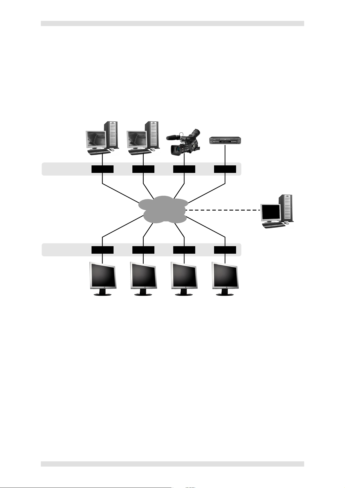
Example System Application
The diagram below shows an example system application utilizing eight VN-MATRIX units. Four are
configured as encoders (sources) and four as decoders (displays). Each device is connected to a
network.
Configuration of each device, including which source is displayed on which display, can be achieved
by any PC/laptop on the same network, using the VN-MATRIX Integrated Web Management System.
SOURCES
SOURCE
1
SOURCE
2
SOURCE
3
SOURCE
4
These VN-MATRIX units are
configured as
These VN-MATRIX units are
configured as
encoders
decoders
DISPLAYS
VN-MATRIX VN-MATRIX VN-MATRIX VN-MATRIX
NETWORK
VN-MATRIX VN-MATRIX VN-MATRIX VN-MATRIX
SOURCE
1
SOURCE
2
SOURCE
3
SOURCE
4
One VN-MATRIX is designated as
a ‘controller’; this unit serves up
the Web Management System to
a browser running on any
networked computer
CONFIG
PC
The Web Management System is
used to view or change settings
of all VN-MATRIX units on the
same network.
In this example each of the four sources is shown separately on the four displays. Potentially
however, any display can display any source.
Page 14 I458GB issue 6
Page 15

VN-MATRIX User Guide Section 1: Introduction
Data Transport Methods
Source data from a VN-MATRIX Encoder can be distributed to multiple displays/encoders (one-tomany) or to a single display/decoder (point-to-point).
Video data is transported from the source (encoder) to the display (decoder) using one of three
methods:
Multicast RTP
Unicast RTP
Unicast TCP
A description of each method, together with its advantages and disadvantages, can be found on the
next few pages.
I458GB issue 6 Page 15
Page 16
Section 1: Introduction VN-MATRIX User Guide
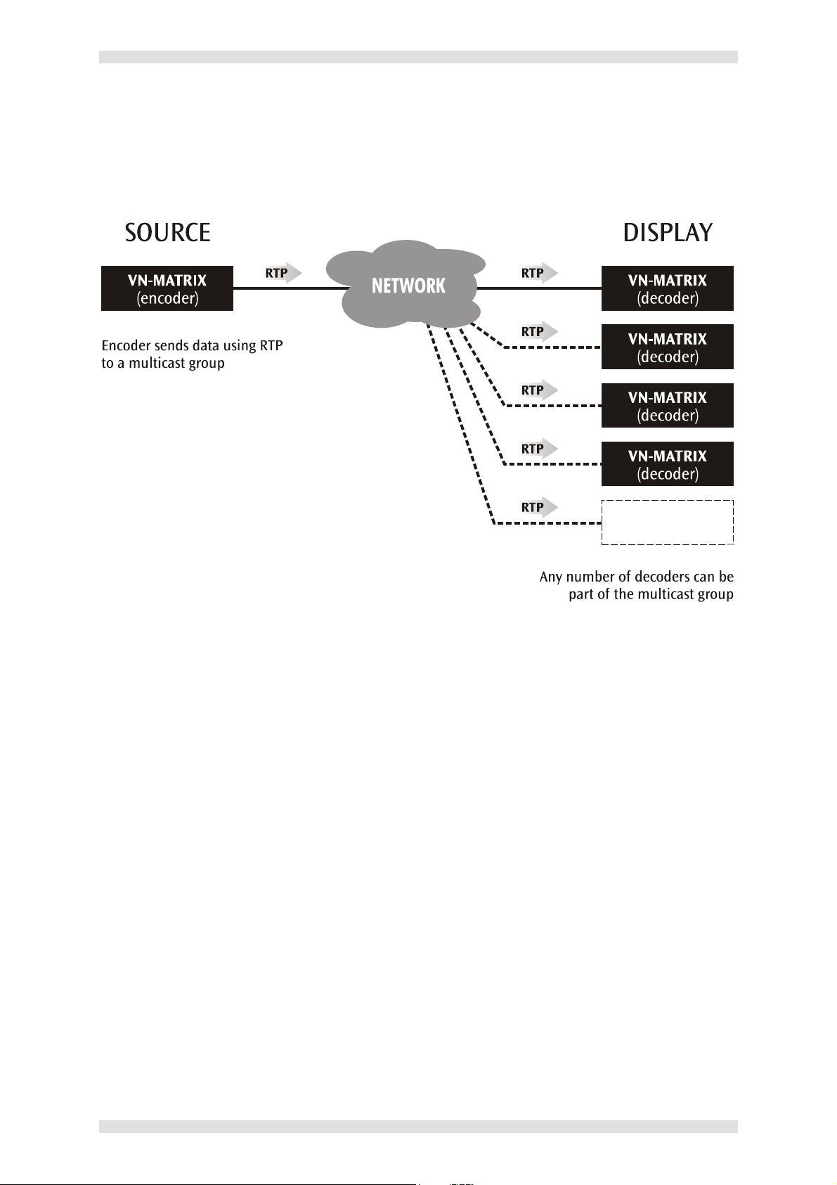
Multicast RTP
This method uses a real-time variation of UDP (User Datagram Protocol), called RTP (Real Time
Protocol). Multicast RTP allows a source to be displayed on any number of displays.
.
The source encoder uses RTP to send data to a multicast group. The source does not need to know
the IP address of any decoders that use that source.
RTP provides very low latency which is important for video transport. Unlike other protocols, RTP
packets include a time-stamp. Therefore, if packets are received in the wrong order they can easily be
sorted into the correct order for display, or discarded if the time stamp is ‘out of date’.
However, because RTP is a connection-less protocol, data delivery is not guaranteed. Where data
packets are lost (e.g. due to excessive network traffic) VN-MATRIX carefully manages the data
stream to minimize any image disruption.
Page 16 I458GB issue 6
Page 17
VN-MATRIX User Guide Section 1: Introduction
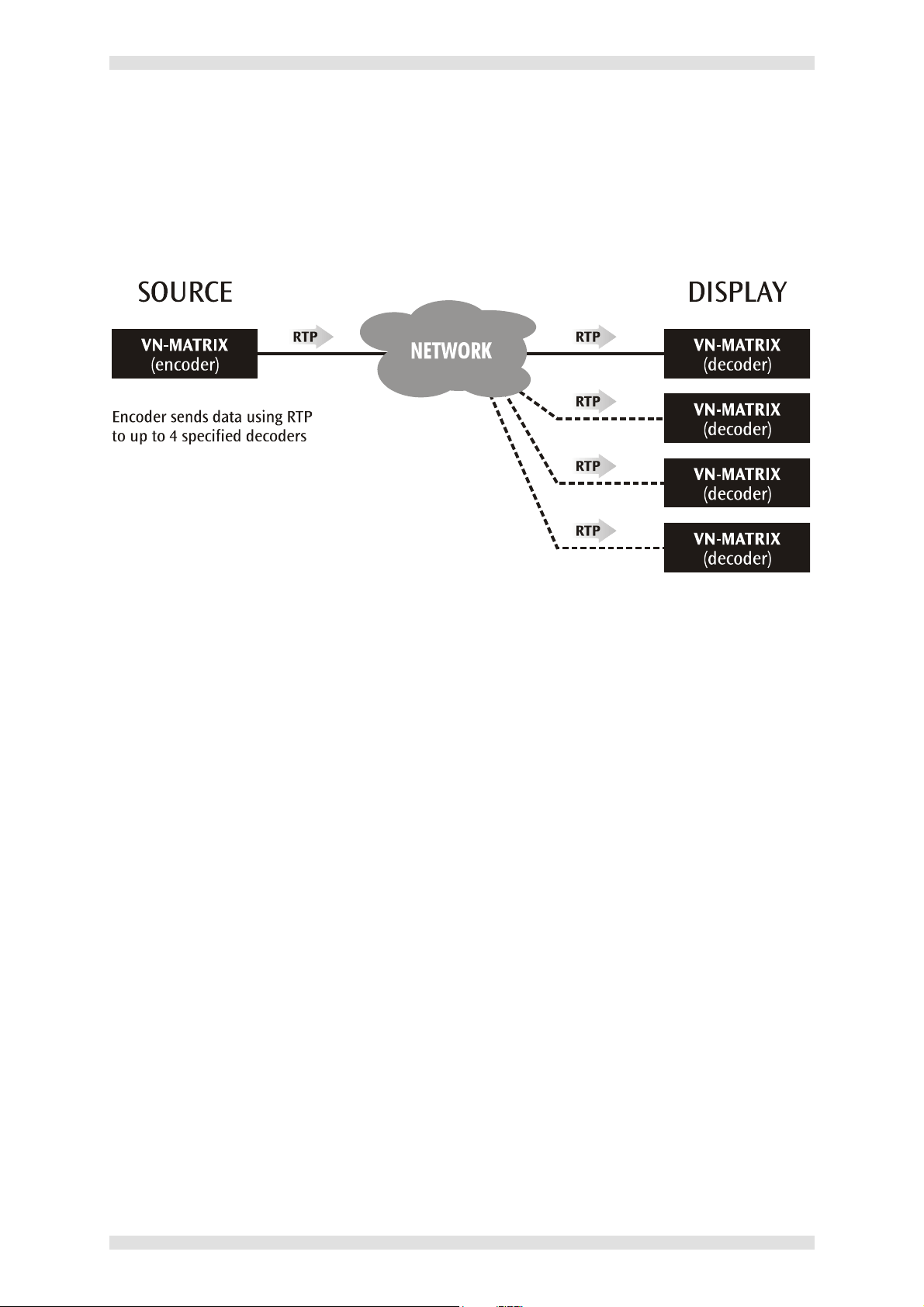
Unicast RTP
Like Multicast RTP this method uses a real-time variation of UDP protocol, called RTP. This method
can be used where the network infrastructure does not support multicast traffic. Typically this should
be used as a point-to-point configuration (i.e. single source to single display) but can be used for up to
four displays.
The source encoder defines the display decoder(s) that the source is available to, but the decoder
chooses which source to display.
RTP provides very low latency which is important for video transport. Unlike other protocols, RTP
packets include a time-stamp. Therefore, if packets are received in the wrong order they can easily be
sorted into the correct order for display, or discarded if the time stamp is ‘out of date’.
However, because RTP is a connection-less protocol, data delivery is not guaranteed. Where data
packets are lost (e.g. due to excessive network traffic) VN-MATRIX carefully manages the data
stream to minimize any image disruption.
I458GB issue 6 Page 17
Page 18
Section 1: Introduction VN-MATRIX User Guide
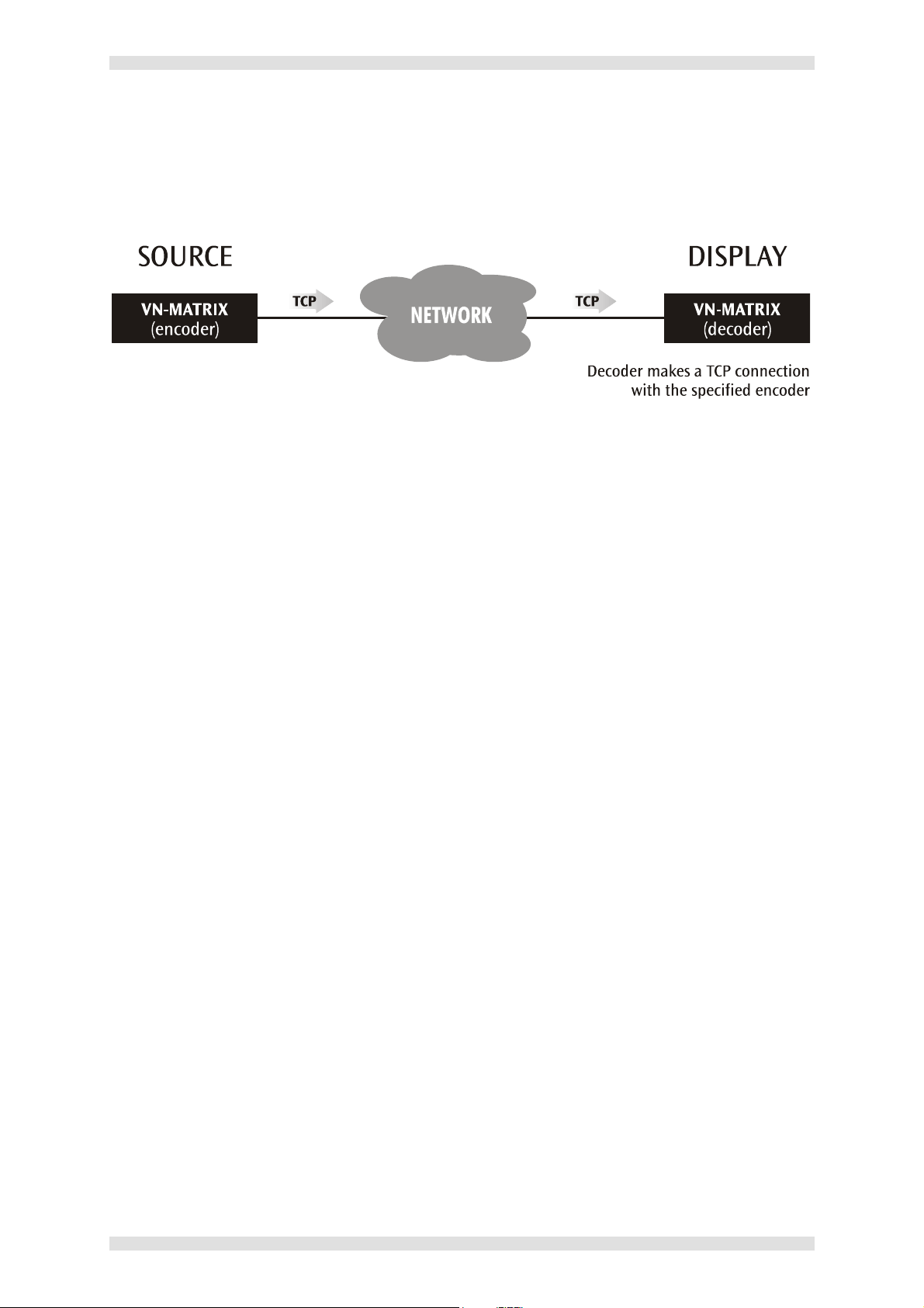
Unicast TCP
This method transports data using standard TCP (Transport Control Protocol) and should only ever be
used for single point-to-point transfer of data.
TCP is a connection-based protocol and, therefore, data is guaranteed to be delivered. However, in
the event of excessive network traffic, delivery may be delayed which will impact on real-time
performance.
The decoder defines which source to ‘connect to’. Other than defining an IP Address and source type
(if required) no special source encoder setup required.
NOTE: Multiple decoder connections are theoretically possible using this method but NOT
recommended. Each additional connection will create extra loading on the encoder CPU which will
ultimately result in poor display performance. In addition, multiple TCP streams carrying the same
source data is an inefficient use of network bandwidth.
Page 18 I458GB issue 6
Page 19
VN-MATRIX User Guide Section 1: Introduction
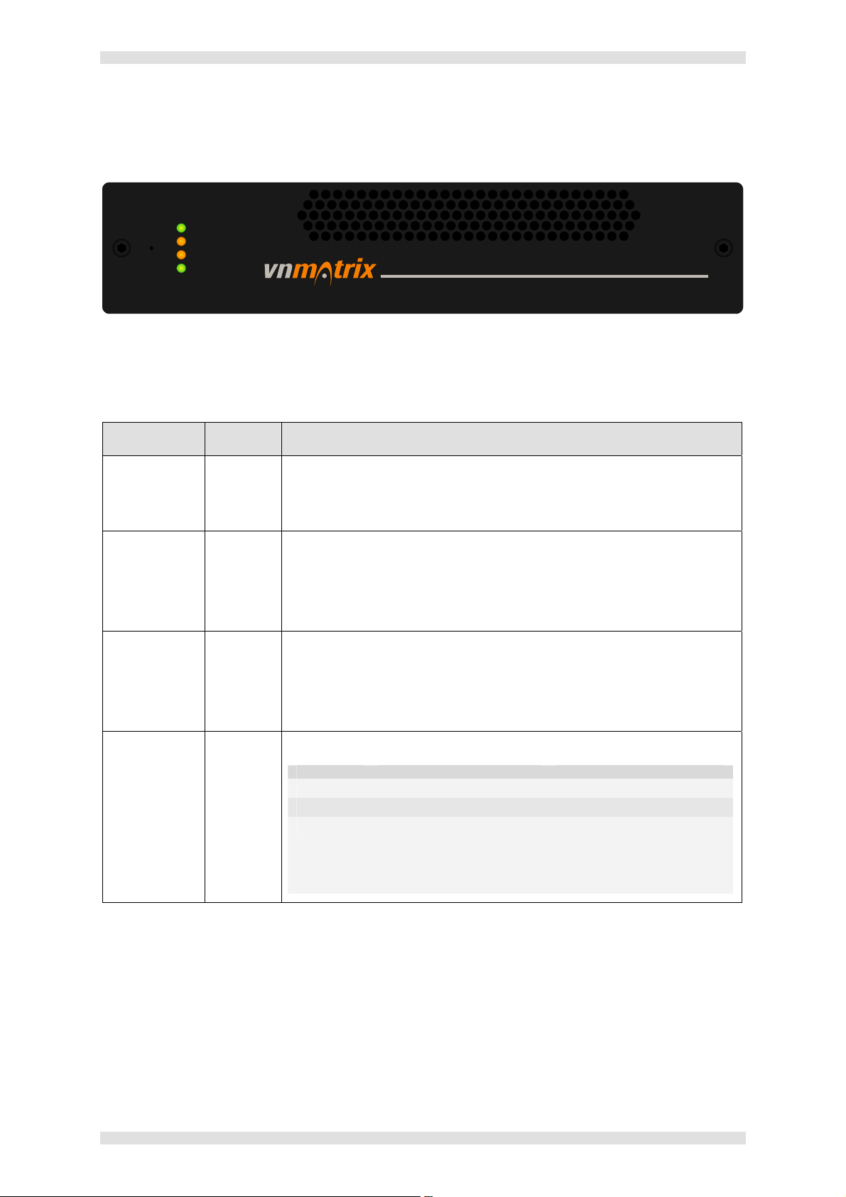
Front Panel Features
POWER
NETWORK I
NETWORK II
STATUS
ELECTROSONIC
Indicators
The following indicators are visible on the front of the VN-MATRIX:
Name Color Function
POWER Green Fully Lit – when the unit is receiving power from the 12V supply input.
Flashing – an over temperature condition has occurred or there was a
power overload/underload condition. Cycle the power off/on to reset.
NETWORK I Orange Indicates the status of network port I:
Fully Lit or Flashing Intermittently – control or source data is being
transmitted or received by the port.
Unlit – no data or no network connection detected.
NETWORK II Orange Indicates the status of network port II:
Fully Lit or Flashing Intermittently – control or source data is being
transmitted or received by the port.
Unlit – no data or no network connection detected.
STATUS
Green Indicates the source status of the VN-MATRIX:
Condition Encoder (source) Decoder (display)
Unlit
Flashing
Fully Lit
No source input detected No source being received
Source being streamed Source being received
Source present but not
n/a
being streamed (e.g. unit
currently disabled or in
standby mode)
NOTE: During the VN-MATRIX boot up period (typically 20-30 seconds) the NETWORK and STATUS
indicators may light up or flash intermittently while the unit initializes.
Reset Button
VN-MATRIX is fitted with a concealed reset button. This can be used to reboot the operating system,
for example during firmware upgrade procedures.
To activate this button, insert the blade of a very small screwdriver (or similar tool) or straightened
paper clip into the hole on the front panel, on the left of the indicators.
I458GB issue 6 Page 19
Page 20
Section 1: Introduction VN-MATRIX User Guide
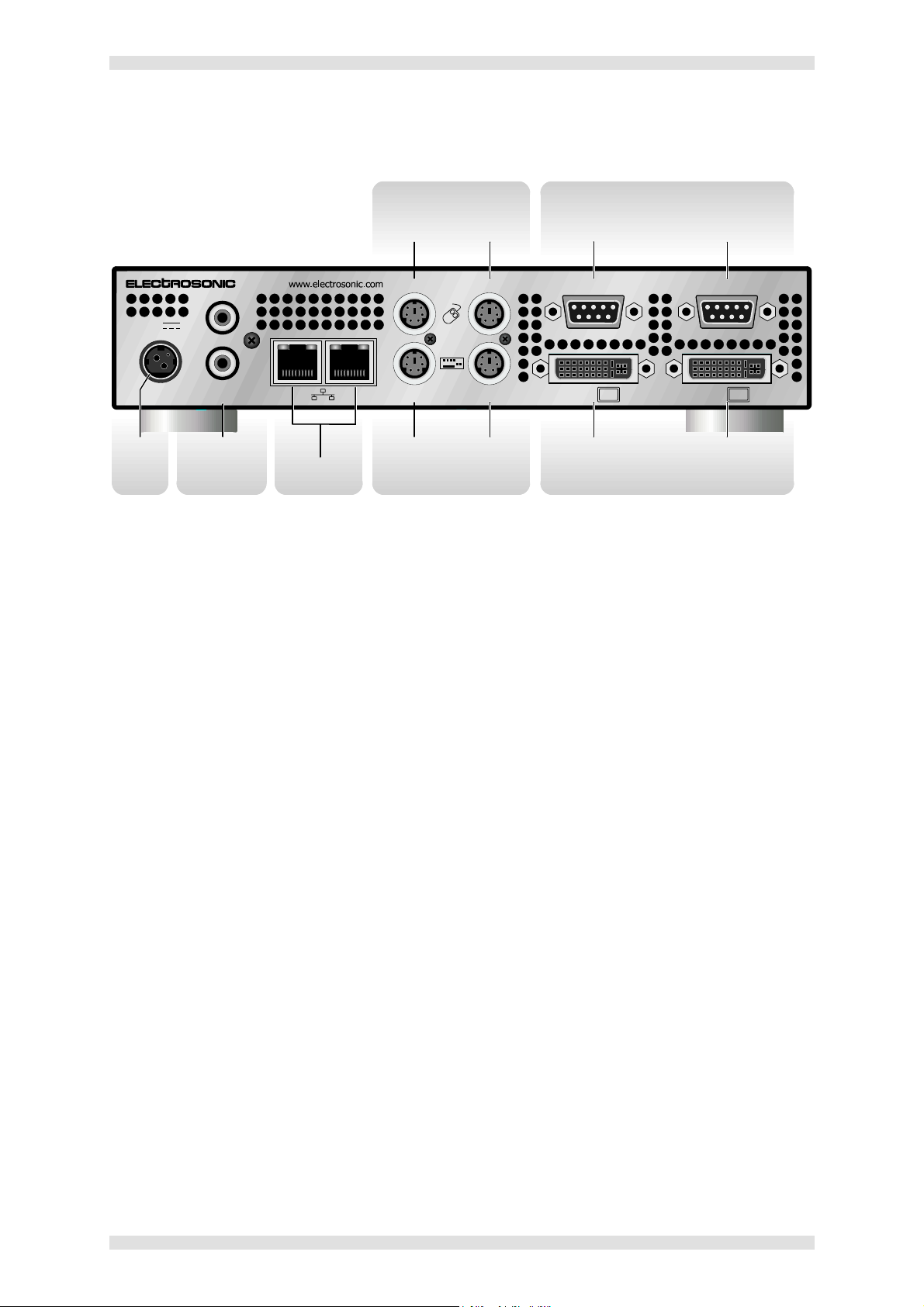
Rear Panel Features
MOUSE CONNECTORS
(PS/2)
Mouse
Computer COM 2
SERIAL I/O CONNECTORS
(RS-232)
COM 1
COM 2
IN
DVI-I
12V DC
REG
POWER
SUPPLY
INPUT
ES3401
IN
OUT
DIGITAL
AUDIO
DIGITAL
AUDIO
CONNECTORS
III6A MAX
NETWORK
CONNECTORS
COM 1
PERIPH PC
Keyboard Monitor
KEYBOARD CONNECTORS
Computer Computer
(PS/2)
OUT
DVI-I
MONITOR CONNECTORS
(DVI-I)
Full details of connector types, pin-outs and specifications can be found in Section 5:Technical Data.
Briefly, these are as follows:
Power Supply Input
The VN-MATRIX requires a 12V DC regulated power supply (rated at 6A) via this connector.
A suitable mains-operated power supply unit (PSU) is provided.
Network Connectors
These are used to connect the VN-MATRIX to an Ethernet network. Typically NETWORK I is used for
data streaming and device configuration (using the Web Interface). NETWORK II port is reserved for
future use and special applications.
Keyboard Connectors
Standard PS/2 connectors, used to connect the VN-MATRIX between the source computer and its
keyboard.
Mouse Connectors
Standard PS/2 connectors, used to connect the VN-MATRIX between the source computer and its
mouse.
Monitor Connectors
Standard DVI-I connectors, used to connect the VN-MATRIX between the source computer and its
monitor. Compatible with both digital and analog sources – see Source Compatibility (page 11).
Serial I/O Connectors
Standard 9-pin connectors used to establish a serial data link between the VN-MATRIX and an
external computer. COM1 is typically used to configure the unit via a serial link. COM2 is typically
used for sending or receiving serial data across a network.
Page 20 I458GB issue 6
Page 21
VN-MATRIX User Guide Section 1: Introduction
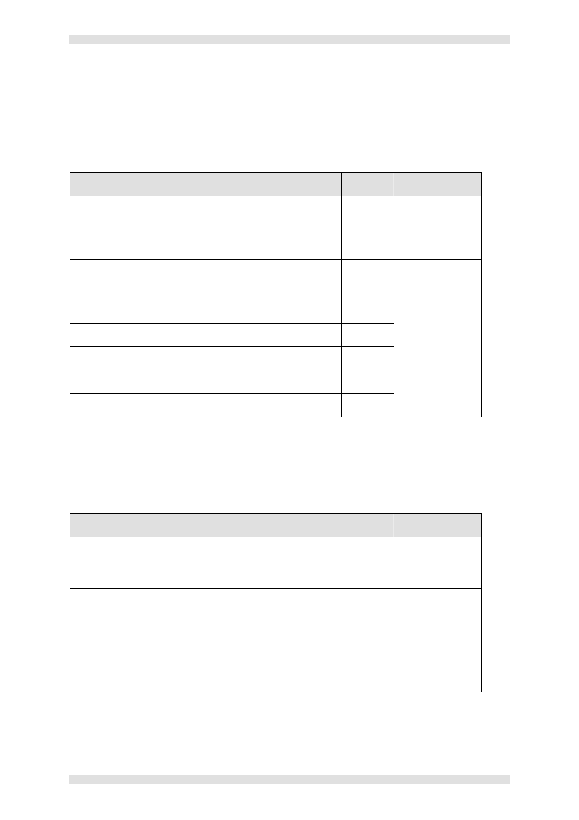
Accessories
Supplied Accessories
In addition to this User Guide, the VN-MATRIX is supplied with the following accessories. If any of
these items is missing or damaged, please contact your Electrosonic dealer immediately:
Item Qty Re-order Code
12V Power Supply Unit (PSU)
Mains Cord for PSU (with 3-pin ‘Edison’ plug)
For use in the USA.
Mains Cord for PSU (bare-ended)
For use in Europe and all other countries.
Digital Monitor Cable (2 metre DVI-D to DVI-D) 1
Analog Monitor Cable (2 metre 15-pin HD-type to DVI-A) 1
DVI-A to 15-pin HD Adapter
Mouse/Keyboard Cable (2 metre PS/2 to PS/2) 2
Serial Cable (9-pin D-type to 9-pin D-type) 1
1 ES3401-P
1 CA4291
1 CA429
Digital Cable Kit:
ES3401-CD
1
Analog Cable Kit:
ES3401-CA
Optional Accessories
The following optional accessories are also available for use with the VN-MATRIX – these must be
ordered separately from your Electrosonic dealer:
Item Order Code
Rack Mounting Kit (single unit)
A kit that allows a VN-MATRIX unit to be installed in a 19 inch equipment
rack. Full instructions are included with the kit.
Rack Mounting Kit (dual unit)
A kit that allows two VN-MATRIX units to be installed, side by side, in a
19 inch equipment rack. Full instructions are included with the kit.
Surface Mounting Kit
A kit that allows a VN-MATRIX unit to be mounted to any convenient flat
surface, e.g. under a desk. Full instructions are included with the kit.
I458GB issue 6 Page 21
ES3401-RM1
ES3401-RM2
ES3401-SM
Page 22

Section 1: Introduction VN-MATRIX User Guide
This page is intentionally left blank.
Page 22 I458GB issue 6
Page 23

VN-MATRIX User Guide Section 2: Installation & Basic Setup Procedures
SECTION 2:
Installation & Basic Setup Procedures
I458GB issue 6 Page 23
Page 24

Section 2: Installation & Basic Setup Procedures VN-MATRIX User Guide
Choosing a Suitable Location
The VN-MATRIX is designed to be used either as a free-standing unit or (by using the optional kits
available) to be mounted in a 19 inch equipment rack.
CAUTION
Whichever installation method you choose there are certain environmental
requirements, detailed on page 25, which must be observed in order to ensure safe
and reliable operation.
For rack-mounted applications the criteria detailed on page 26, must also be
observed.
Page 24 I458GB issue 6
Page 25

VN-MATRIX User Guide Section 2: Installation & Basic Setup Procedures
Environmental Requirements
CAUTION
The criteria on this page must be observed for all installations of the VN-MATRIX,
whether free-standing or rack-mounted.
Orientation
The VN-MATRIX is designed to be used free-standing on a stable, horizontal surface. It can, however,
be used in any orientation subject to the necessary ventilation requirements.
Temperature
DO NOT install or operate the VN-MATRIX in an area where the ambient temperature exceeds 35°C
(95°F) or falls below 5°C (35°F).
Remember that, as with all electronic equipment, the VN-MATRIX and its associated PSU also
produces heat which may affect the ambient temperature.
After the VN-MATRIX has been in use for a period of time the external casing may become slightly
warm to the touch. Ensure that any adjacent surfaces will not be affected by the heat.
Ventilation
DO NOT obstruct the ventilation grilles during use. The VN-MATRIX has an integral forced-air cooling
system. A fan draws air in through the grille in the front panel and expels ‘warmed’ air through the
grilles in the back panel. The fan speed is controlled automatically by an internal temperature sensor.
The fan may, therefore, appear to run faster as the unit warms up or if the ambient temperature is
increased.
A self-resetting thermal cut-out will shutdown the VN-MATRIX if the temperature exceeds design
limits.
Humidity & Water
DO NOT install or operate the VN-MATRIX in an area in which the ambient relative humidity exceeds
85% or in an area that is prone to condensation.
DO NOT install or operate the VN-MATRIX near water or in a location which may be prone to water
seepage — the VN-MATRIX is not waterproof.
I458GB issue 6 Page 25
Page 26

Section 2: Installation & Basic Setup Procedures VN-MATRIX User Guide
Rack-mount Requirements
CAUTION
For rack-mounted installations, the following criteria must be observed (in addition to
the Environmental Requirements listed on page 25)
Mounting & Support
ALWAYS use the special rack-mount kits (available separately) to secure the VN-MATRIX. Full
details on using the kit are included with the kit. It will be necessary to remove the four feet prior to
rack mounting.
DO NOT stand other units directly on top of the VN-MATRIX when it is rack-mounted as this will place
excessive strain on the mounting brackets.
Ventilation
ALWAYS ensure that the rack enclosure is adequately ventilated. Sufficient airflow must be achieved
(by convection or forced-air cooling) to satisfy the ventilation requirements of all items of equipment
installed within the rack.
No additional ventilation gap is required above or below the VN-MATRIX and adjacent surfaces or
equipment.
Mains Supply
ALWAYS ensure that the mains power supply is of the correct voltage and frequency for all
equipment within the rack, and that it has a good ground/earth connection.
Where a power strip (mains distribution batten) is used (of either a hard-wired or plug and socket
type), always ensure that the current rating of both the power strip and the supply is sufficient for all
equipment within the rack.
Page 26 I458GB issue 6
Page 27

VN-MATRIX User Guide Section 2: Installation & Basic Setup Procedures
Mains Power Connection (via PSU)
The VN-MATRIX must be powered from a 12 Volt DC regulated supply. A suitable mains-operated
power supply unit (PSU) is provided. The mains connection details that follow relate to the PSU.
NEVER CONNECT THE VN-MATRIX DIRECTLY TO THE MAINS.
To ensure CE compliance ALWAYS use the PSU provided.
If a backup/replacement PSU is required, always use an Electrosonic
approved PSU.
Supply Requirements (for PSU)
ALWAYS observe the following instructions to ensure safe and reliable
operation of the PSU.
ALWAYS ensure that the mains supply voltage is single phase only and is within the permitted range:
100 – 240V AC (0.45A Max.) 50 – 60Hz.
NEVER connect the PSU to a DC supply.
DO NOT allow the mains power point to be overloaded. This is particularly important to check when
powering several items of equipment from a single power point (e.g. within rack-mounted
installations).
WARNING: THIS EQUIPMENT MUST BE GROUNDED / EARTHED.
WARNING: To avoid the possible risk of electric shock or product damage due to condensation,
ALWAYS allow the PSU to become acclimatized to ambient temperature and humidity for at least
thirty minutes BEFORE switching on. This is particularly important when moving the unit from a cold
to a warm location.
I458GB issue 6 Page 27
Page 28

Section 2: Installation & Basic Setup Procedures VN-MATRIX User Guide
Mains Power Cord (for PSU)
The mains PSU is equipped with a 3-pin (male) type mains connector which requires a power cord
fitted with a corresponding 3-pin IEC320 (female) connector.
Two power cords are supplied with the PSU, each having a different termination; you must use the
lead appropriate for your country:
In... Use the... Re-order Code
USA and Canada
UK, Europe and all
other countries
WARNING: Do not allow anything to rest on the mains power cord.
cord fitted with the 3-pin
American-style ‘Edison’ plug.
unterminated cord and fit a
suitable plug as described on
page 29.
CA4291
CA429
Power-up Procedure
You must always ensure that the VN-MATRIX is powered-up at the same time as the source
computer or slightly before.
Powering the VN-MATRIX after the source computer may result in the source computer not correctly
detecting the mouse, keyboard and/or monitor.
Page 28 I458GB issue 6
Page 29
VN-MATRIX User Guide Section 2: Installation & Basic Setup Procedures
Fitting a Mains Plug
If you are fitting a plug to the unterminated power cord (or replacing an existing plug), you must fit a
plug that:
• is rated for use with mains voltage
• is equipped with a grounding pin/connection
• complies with any applicable National or Local electrical regulations.
• is fitted with a correctly rated fuse (applicable to UK-style plugs only – see page 30.)
WARNING: Never attempt to fit or use a plug without a ground or earth pin/connection.
Wiring Details
The wires of both mains power cords (supplied with each VN-MATRIX) are color-coded as shown in
the table below; be sure to connect your plug in accordance with the following guidelines:
Connect the wire
colored...
Brown
Blue
Green & Yellow
WARNING — If you are unsure of the connections,
or if the markings in your plug do not match those
given above, CONSULT A QUALIFIED ELECTRICIAN.
NOTE: The PSU is double-insulated and does not require an earth/ground connection. However, the
earth cable of the mains lead must be connected in the plug.
to the plug terminal identified
with...
‘L’ or ‘Live’ or ‘Line’
(or colored red or brown)
‘N’ or ‘Neutral’
(or colored blue or black)
‘E ’ or ‘E’ or ‘Earth’ or ‘Ground’
(or colored green or green & yellow)
I458GB issue 6 Page 29
Page 30
Section 2: Installation & Basic Setup Procedures VN-MATRIX User Guide
External Supply Protection
The mains power cord supplied with this product is rated at 10A maximum and
must be protected from overload by an external fuse or circuit breaker.
Fused Plugs (UK-style)
If the power cord is fitted with a UK-style BS1363 3-pin plug (i.e. with provision for an internal fuse),
then it must be fitted with a BS1362 ASTA approved 1 inch cartridge fuse.
This fuse must be rated at a maximum of 10A/250V. Since the current draw of the PSU is less than
1A, a fuse of a lower rating not less that 3A/250V may be used.
WARNING: Never attempt to fit a fuse or circuit breaker of a higher maximum rating than shown
above.
Unfused Plugs or Hard-wired
If the power cord is fitted with an unfused plug, or is hard-wired into a power strip (mains distribution
batten), then the power cord must be protected by an external fuse or circuit breaker of a rating shown
in the table below:
Supply Voltage
Maximum Fuse Rating 10A 10A
Minimum Fuse Rating 3A 3A
WARNING: Never attempt to fit a fuse or circuit breaker of a higher
maximum rating than shown above.
110V nominal 230V nominal
Page 30 I458GB issue 6
Page 31

VN-MATRIX User Guide Section 2: Installation & Basic Setup Procedures
Setup and Connection Procedure
Setting up and connecting a VN-MATRIX system is best undertaken in three stages. Briefly these are:
Stage 1: Network Communications Setup
Configure the network settings for each device using a PC/laptop and serial data link,
ensuring that one device is configured as a controller. (See pages 32 to 34).
Stage 2: Connection
Connect each device to the network and connect its associated source or display equipment.
(See pages 35 to 40).
Stage 3: System Configuration
Using a PC/laptop connected to the same network to access the Web Interface (served by the
controller) configure each device to be an encoder (source) or decoder (display).
(See Section 3, page 41 onwards).
CAUTION: Do not proceed with connecting or configuring the VN-MATRIX for an existing network
until you are certain you know what you are doing – incorrect connection or configuration may cause
disruption to other network users.
I458GB issue 6 Page 31
Page 32

Section 2: Installation & Basic Setup Procedures VN-MATRIX User Guide
SU
Network Communications Setup
To establish a serial communications link…
Using a null modem type serial cable, connect the serial port of a PC/laptop to the COM1 serial
port on the VN-MATRIX to be configured:
CONFIG
PC
ES3401
VN-MATRIX
12V DC
REG
6A MAX
OUT
DIGITAL
AUDIO
ES3401
IN
III
PERIPH PC
COM 1
DVI-I
OUT
COM 2
DVI-I
IN
PSU
MAINS
PPLY
On the PC/laptop run a terminal emulation program such as HyperTerminal, with the following
comms settings:
Baud rate: 115200
Data bits: 8
Parity: None
Stop bits: 1
Flow control: None
NOTE: HyperTerminal is supplied with all Windows operating systems.
Page 32 I458GB issue 6
Page 33

VN-MATRIX User Guide Section 2: Installation & Basic Setup Procedures
To access the setup menus…
Connect the power to the VN-MATRIX (or, if already connected, cycle the power off then on).
VN-MATRIX will commence sending setup/diagnostic data which should appear in the
HyperTerminal window. After a few seconds this will conclude with something like:
VN Matrix(R) Maintenance Console: ver3.1c
(none) login: ThorPci Init
registering plx interrupt routine = D17F89FC, -780166896
Hello kernel
thor_init_module: pre-ioremap
thor_init_module: post-ioremap
Hello kernel, this is MK registering
registering plx interrupt routine = D296BD30, 0
Press the <enter> key: the VN-MATRIX should respond with the following login prompt:
VN Matrix(R) Maintenance Console: ver3.1c
192.168.0.1 login:
NOTE: The login prompt will be preceded by the current IP Address of the unit.
Type config followed by the <enter> key.
When prompted for a password type config followed by the <enter> key.
The following menu will then appear:
Network Port 1 Network Port 2
============== ==============
1. Boot method: static [dhcp] 11. Boot method: static [dhcp]
2. address: 192.168.0.18 12. address: 192.168.1.18
3. netmask: 255.255.255.0 13. netmask: 255.255.255.0
4. gateway: 192.168.0.1
5. broadcast: 192.168.0.255 15. broadcast: 192.168.1.255
6. mtu: 1500 16. mtu: 1500
7. controller ip: 192.168.0.18
8. controller port: 5432 18. webserver port: 80
9. Exit
Change the settings as required by typing the option number followed by the <enter> key. Then
type the new value followed by the <enter> key.
For example, to change the Network Port 1 IP address to 172.28.232.16:
type 2 <enter> then type 172.28.232.16 <enter>
NOTE: Do not include any leading zeros when typing IP addresses.
For example, type 192.168.0.18 and not 192.168.000.018.
I458GB issue 6 Page 33
Page 34

Section 2: Installation & Basic Setup Procedures VN-MATRIX User Guide
NOTES
For advice on choosing IP Addresses, see Appendix A on page 126.
For normal applications only Network Port 1 settings need to be configured.
Option 1 and 11 are toggle action. For example, to switch between static and dchp modes
simply type 1 <enter>. The currently selected mode is the option listed first. When DHCP
mode is selected, options 2, 3, 4 & 5 (or 12, 13 & 14) will not be displayed.
Remember that one (and only one) VN-MATRIX must be configured as a controller (see
below). The controller IP (option 8) must be set to the IP Address of the unit designated as
the controller.
Gateway (option 4) is generally only required if devices are on different subnets.
To configure VN-MATRIX as a controller…
Ensure the boot method for Network Port 1 is set to static (option 1).
Set the IP Address (option 2) and controller IP (option 8) to the same value.
To implement the new settings…
Once you have made completed any changes, type 9 <enter> to exit the menu.
The VN-MATRIX will now reboot automatically to implement the new settings.
If the unit does not reboot for any reason, or you want to perform a manual reboot, type reboot
<enter> at the command prompt (or cycle the power off and on) to reboot the unit and implement
the new settings.
VN-MATRIX is now ready for connection to the network.
Page 34 I458GB issue 6
Page 35

VN-MATRIX User Guide Section 2: Installation & Basic Setup Procedures
Connections
Supplied Cables
A set of cables is supplied with VN-MATRIX to accommodate a variety of standard connection
requirements.
The VN-MATRIX is compatible with both digital (DVI) and analog graphics signals. The unit is
provided with the necessary additional cables that you may require.
Source (encoder) Display (decoder) Cable Description
Digital Analog Digital Analog
Mouse/Keyboard Cable (PS/2 to PS/2) (2 off)
Digital Monitor Cable (DVI-D to DVI-D)
Analog Monitor Cable (15-pin Hi-D D-type to DVI-A)
DVI-A to 15-pin Hi-Density D-type Adapter
For Connection Diagram see page…
IMPORTANT NOTES
Disconnecting and reconnecting PS/2 cables to a computer that is already switched on may cause
loss of mouse/keyboard control or cause the computer to ‘freeze’. It is recommended, therefore, that
the connections are made while the computer is powered-down. See also ‘Power-up Procedure’ on
page 28.
If you use a monitor cable or adapter other than that provided with the VN-MATRIX (as an encoder)
you must ensure that all pins are properly interconnected, otherwise the computer graphics card or
monitor may not operate correctly.
37 38 39 40
I458GB issue 6 Page 35
Page 36

Section 2: Installation & Basic Setup Procedures VN-MATRIX User Guide
Network Connection
CAUTION: Do not proceed with connecting VN-MATRIX to an existing network until it is correctly
configured using the procedure in Stage 1 (See pages 32 to 34). Incorrect connection or configuration
may cause disruption to other network users.
Typically, the VN-MATRIX will connect to convenient network point on an existing in-house network.
Use a standard CAT 5E or CAT 6 (or better) patch cable for this purpose. A patch cable is not
supplied with the VN-MATRIX but is readily available in a variety of lengths from all good computer
suppliers.
If a convenient network point is not available it will be necessary to have one installed – please
consult the IT/Network Administrator or Building Facilities Manager for advice. Alternatively, the VNMATRIX and source computer can ‘share’ a connection by using a switcher. Hubs are not suitable for
use with VN-MATRIX as they restrict bandwidth.
For normal VN-MATRIX operation use Network Port I only.
HINT: With the VN-MATRIX powered and connected to a network the Network Status Indicator
(next to the network connector) should be lit:
Page 36 I458GB issue 6
Page 37

VN-MATRIX User Guide Section 2: Installation & Basic Setup Procedures
Connecting a Digital Source
SOURCE COMPUTER
DVI monitor outkeyboard
ES3401
VN-MATRIX
(Encoder)
PSU
12V DC
REG
OUT
DIGITAL
AUDIO
NETWORK
IN
Phono
to
Phono
ES3401
COM 2
IN
DVI-D
to
DVI-D
DVI-I
PS/2
to
PS/2
III6A MAX
PERIPH PC
IMPORTANT!
Fit clip-on ferrite
to this end of cable
COM 1
DVI-I
OUT
MAINS
SUPPLY
DVI
MONITOR
I458GB issue 6 Page 37
Page 38

Section 2: Installation & Basic Setup Procedures VN-MATRIX User Guide
Connecting an Analog Source
SOURCE COMPUTER
NETWORK
ES3401
VN-MATRIX
(Encoder)
12V DC
REG
IN
OUT
DIGITAL
AUDIO
Phono
to
Phono
ES3401
keyboard
PS/2
to
PS/2
III6A MAX
PERIPH PC
IMPORTANT!
Fit clip-on ferrite
to this end of cable
COM 1
DVI-I
OUT
analog monitor out
15pin
HD-type
DVI-A
COM 2
DVI-I
IN
DVI-A to
15pin HD-type
Adapter
to
PSU
MAINS
SUPPLY
NETWORK
ANALOG
MONITOR
Page 38 I458GB issue 6
Page 39

VN-MATRIX User Guide Section 2: Installation & Basic Setup Procedures
S
Connecting a Digital Display
MAIN
SUPPLY
PSU
ES3401
VN-MATRIX
(Decoder)
NETWORK
12V DC
REG
DIGITAL
6A MAX
AUDIO
IN
OUT
ES3401
Phono
to
Phono
III
PERIPH PC
OUT
COM 1
COM 2
DVI-I
DVI-I
IN
AMPLIFIER
DVI
DISPLAY
NOTE: VN-MATRIX provides both an analog and digital output signal regardless of
the original source format.
I458GB issue 6 Page 39
Page 40

Section 2: Installation & Basic Setup Procedures VN-MATRIX User Guide
A
S
Connecting an Analog Display
MAIN
SUPPLY
PSU
ES3401
VN-MATRIX
(Decoder)
NETWORK
12V DC
REG
DIGITAL
6A MAX
AUDIO
IN
OUT
ES3401
Phono
to
Phono
III
PERIPH PC
OUT
COM 1
COM 2
DVI-I
DVI-I
IN
DVI-A to
15pin HD-type
Adapter
AMPLIFIER
NALOG
DISPLAY
NOTE: VN-MATRIX provides both an analog and digital output signal regardless of
the original source format.
Page 40 I458GB issue 6
Page 41

VN-MATRIX User Guide Section 3: System Configuration
SECTION 3:
System Configuration
I458GB issue 6 Page 41
Page 42

Section 3: System Configuration VN-MATRIX User Guide
The VN-MATRIX Web Interface
Once all VN-MATRIX devices have been correctly set-up for (and connected to) a network, any
system further configuration is achieved via the VN-MATRIX Web Interface. This comprises a number
of ‘pages’ which provide access to various system parameters.
HINT: This section provides step-by-step instructions for using the Web Interface and is aimed at
new users of the VN-MATRIX system. Advanced users may wish to refer to the Quick
Reference Guide in Section 7, pages 107 to 123.
The Web interface is ‘served up’ by the VN-MATRIX device that was designated as the ‘controller’
during the network set-up procedure (see page 34). It can be viewed by any up-to-date web browser,
running on a PC/laptop that is connected to the same network as the VN-MATRIX devices.
Suitable browsers include (but are not necessarily limited to):
Internet Explorer (v6 and above),
Firefox/Mozilla (v1.3 and above).
Netscape (v6 and above), and
IMPORTANT: Whatever browser is used, it must be configured to accept cookies and be
JavaScript-enabled. For further help on configuring your browser, refer to
Appendix C (page 133 onwards).
Page 42 I458GB issue 6
Page 43

VN-MATRIX User Guide Section 3: System Configuration
Accessing the Web Interface
Use the address box of your chosen browser to enter the following URL:
http://xxx.xxx.xxx.xxx
where xxx.xxx.xxx.xxx is the IP address of the VN-MATRIX controller.
The following page will appear in the browser:
Click the text as directed to reveal the login screen:
Enter the appropriate User name and Password.
VN-MATRIX has two user accounts:
admin – which allows full read/write access to all setup parameters,
public – which allows read only access to setup parameters.
Initially the password for both accounts is the same as the user name (i.e. the account name).
It is recommended that these are changed once commissioning is complete (see page 81).
Click the Login button.
If the login details are correct the Device List page will appear (see next page).
I458GB issue 6 Page 43
Page 44

Section 3: System Configuration VN-MATRIX User Guide
The Device List Page
This page lists all VN-MATRIX devices detected on the network.
NOTE: If devices are added after this page is displayed they will not automatically appear on this list.
You will need to refresh the list by clicking the Device List tab, or by clicking the browser
Refresh/Reload button.
Once a VN-MATRIX device has been detected and been listed on the Device List page, an entry will
be displayed even if the device is subsequently disconnected. All valid devices are listed by device
name and followed by their current IP address. ‘Missing’ devices are easily identified by the lack of an
IP Address. In the above example, the last device in the list (device 620098) is not currently available
(e.g. may be disconnected from the network or powered-down).
The current configuration status of each device is also identified by an icon:
unconfigured
configured as an encoder (source)
configured as a decoder (display)
In a new system, all VN-MATRIX devices will typically be in an unconfigured state. The remainder of
this section will guide you through the process of configuring each VN-MATRIX as either an encoder
(source) or decoder (display).
Page 44 I458GB issue 6
Page 45

VN-MATRIX User Guide Section 3: System Configuration
On-line Help
On-line help is available for each page in the Web Interface by simply clicking the tab.
Interface Timeout & Logging Out
If the web interface is left unattended or is not used for a period of 30 minutes it will automatically
logout. You can start using the interface again by re-entering your login details.
To logout of the Web Interface…
Click the tab on any page.
Update Button and Save Tab
Most pages in the web interface have an Update button and/or a Save tab:
Clicking the Update button implements the settings for the current page/device
but does not save them to the VN-MATRIX flash memory, i.e. if the unit is rebooted
the previous settings will be used.
Clicking the Save tab implements the settings for the current page/device
and does save them to the VN-MATRIX flash memory.
On the Device List page only there is a SaveAll tab:
Clicking the SaveAll tab will save all current settings (including those that have been
‘updated’) for all VN-MATRIX units.
I458GB issue 6 Page 45
Page 46

Section 3: System Configuration VN-MATRIX User Guide
Configuring a VN-MATRIX as an Encoder (source)
The following procedure assumes that a valid source is connected to the VN-MATRIX.
For details on how to connect a source, see page 37 and 38.
NOTE: This procedure provides a basic level of configuration which will be adequate for most
systems. For additional ‘Advanced Setup’ options, see pages 62 to 74.
On the Device List page click the
n
device that you want to configure.
The Device page will then appear…
HINT: You can change the default device Name to be
more relevant to the source input (e.g. Camera1).
NOTE: Device names can use letters and numbers, as
well as the underscore and hyphen characters, but must
not include spaces.
Click the create source button.
o
Turn to page 47.
Page 46 I458GB issue 6
Page 47

VN-MATRIX User Guide Section 3: System Configuration
p
Click the Save tab.
Check that the Mode
p
q
field is set to enable.
For more information, see
‘Device Mode’ on page 49.
Click the videoPort0 icon.
r
HINT: To help identify this device
during set-up or troubleshooting,
tick the Identify box to display the
device name on the local monitor
(where connected).
For more information, see
‘Identify Mode’ on page 49.
The Configure page will appear…
Check that the Input Mode is set to auto.
s
If not, see ‘Input Mode’ on page 49.
Check that the Current Mode shows
t
the format of the connected source.
If not, see ‘Input Mode’ on page 49.
Tick the Multicast Enable box if RTP Multicast
u
source streaming is required, otherwise ensure
this box is unticked to enable RTP Unicast.
Does the source have an audio channel?
v
NO…
Encoder setup is complete, click the tab.
If a local monitor is connected it should now be displaying the source.
If not, see ‘Source Checkup on page 1058.
YES…
Turn to page 48 and follow
‘Additional Setup for Audio’
Repeat this procedure (from page 46, step n ) for each encoder in the system.
w
To configure a VN-MATRIX device as a decoder (display), turn to page 51.
HINT: If your source or local
monitor uses EDID, you may
need to look at these settings.
For more information, see
‘EDID O
tions’ on page 49.
I458GB issue 6 Page 47
Page 48

Section 3: System Configuration VN-MATRIX User Guide
Additional Setup for Audio
Click the Device tab to
n
return to the Device page…
Click the audioPort0 icon.
o
The Configure page will appear…
Check that the Audio Status shows a valid
p
audio source type. If not, see page 50.
Ensure that Compression is set
q
to no compression.
For further information on this feature, see page 73.
Tick the Multicast Enable box if RTP Multicast
r
source streaming is required, otherwise ensure
this box is unticked to enable RTP Unicast.
This must be the same as the videoPort setting.
Encoder setup is now complete, click the tab.
s
Additional Information for Encoder Setup
Repeat this procedure (from page 46, step n ) for each encoder in the system.
To configure a VN-MATRIX device as a decoder (display), turn to page 51.
Page 48 I458GB issue 6
Page 49

VN-MATRIX User Guide Section 3: System Configuration
Input Mode
The default and recommended input mode for a VN-MATRIX encoder is auto. This mode provides full
detection of the applied source and automatic configuration of input parameters. It has the additional
advantage that if a different source is connected at any time, the VN-MATRIX will automatically reconfigure the input for the new source.
Auto mode will detect most standard video and graphic source formats. However, if the source input:
is a non-standard format,
is an RGsB (sync on green) or YPrPb source type,
has a poor quality signal,
has Macrovision
®
copy protection
then VN-MATRIX may not auto-detect correctly. In these cases, to achieve reliable operation, some
fine-tuning may be necessary. A pre-defined or custom input mode can also be applied.
For further information, see ‘Advanced Source Setup’ on page 63.
EDID Options
Many modern computers and monitors are capable of using EDID (Extended Display Identification
Data). This allows a computer graphics card to be ‘aware’ of the capabilities of the display connected
to it. VN-MATRIX, when configured as an encoder, provides different options for handling EDID.
The Monitor EDID field shows the local monitor display
type. If no local monitor is connected or the monitor does
not support EDID, this will show No Device.
The Reported EDID field shows the EDID that VN-MATRIX
reports back to the source device. Transparent mode will
report the current or last connected monitor type.
Alternatively, choose one of the listed display types.
Identify Mode
As an aid to setting-up a VN-MATRIX encoder
in a large or complex system, use the Identify
function to display the device name on the
local monitor (if fitted).
Tick the Identify checkbox, then click the
update button. The device name will appear
on the local display (see example right).
NOTES
The name will only display if a valid
source is connected and has been
correctly detected by VN-MATRIX.
The name only displays on the local
display output. It does not appear as
part of the streamed source.
I458GB issue 6 Page 49
Page 50

Section 3: System Configuration VN-MATRIX User Guide
Device Mode
A VN-MATRIX encoder can be configured in three modes:
enable allows the source to be streamed,
disable prevents a source from being streamed,
standby prevents a source from being streamed.
For normal operation, enable must be selected.
Audio Status
Where a valid digital audio signal is connected to the DIGITAL AUDIO IN connector, the type of signal
will appear in the Audio Status field on the Configure (audioPort) page.
VN-MATRIX supports the auto-detection of 44100 Hz and 48000 Hz digital audio sources.
Advanced Setup Options
The encoder set up procedure on the preceding pages will achieve a basic level of operation which
will be adequate for most normal applications.
The following advanced setup options are possible and these are detailed in Section 4:
Fine-tuning of input parameters see page 65
Creation of custom input modes see page 66
Changing video compression see page 69
Managing bandwidth usage see page 72
Changing audio compression see page 73
Page 50 I458GB issue 6
Page 51

VN-MATRIX User Guide Section 3: System Configuration
Configuring a VN-MATRIX as a Decoder (display)
The following procedure assumes that at least one VN-MATRIX encoder has been configured and is
ready to stream a source (see page 46)
It is also assumed that a suitable display device is connected to the VN-MATRIX.
For details on how to connect a display, see pages 39 and 40.
NOTE: This procedure provides a basic level of configuration which will be adequate for most
systems. For additional ‘Advanced Setup’ options, see pages 74 to 81.
On the Device List page click the
n
device that you want to configure.
The Device page will then appear…
HINT: You can change the default device Name to be
more relevant to the source input (e.g. Screen1).
NOTE: Device names can use letters and numbers, as
well as the underscore and hyphen characters, but must
not include spaces.
Click the create display button.
o
Turn to page 52.
I458GB issue 6 Page 51
Page 52

Section 3: System Configuration VN-MATRIX User Guide
pag
Click the Save tab.
q
Check that the Mode
p
field is set to enable.
For more information, see
‘Device Mode’ on page 54.
Click the display0 icon.
r
The Display page will appear…
HINT: To help identify this device
during set-up or troubleshooting,
tick the Identify box to display the
device name on the local monitor
(where connected).
For more information, see
‘Identify Mode’ on page 54.
Check that the Output Format is set to auto.
s
This forces the output format to be the same as the
chosen source.
If the source type is RGsB
s
(sync on green), ensure that
SoG is ticked. Otherwise it
should be left unticked.
This forces the output format to be
HINT: The Nodata Splash option determines how
the display output behaves if no source is selected
or if the source stops streaming for some reason.
For more information, see ‘Nodata Splash Mode’
e 49.
on
the same as the chosen source.
Page 52 I458GB issue 6
Page 53

VN-MATRIX User Guide Section 3: System Configuration
Select one of the available source streams.
t
Each source is listed by the device name, videoPort
name and suffixed by the connection type:
_rtp is an RTP Unicast connection,
_rtp(m) is an RTP Multicast connection,
_tcp is a TCP Unicast connection.
If the chosen source has an audio channel,
u
tick the audio enable box. Otherwise leave
this box unticked.
Click Update and Save.
v
The chosen source should now appear on the output display.
If not, please refer to ‘Display Checkup’ on page 57.
I458GB issue 6 Page 53
Page 54

Section 3: System Configuration VN-MATRIX User Guide
Additional Information for Decoder Setup
Identify Mode
As an aid to setting-up a VN-MATRIX decoder
in a large or complex system, use the Identify
function to display the device name on the
display output.
Tick the Identify checkbox, then click the
update button. The device name will appear
on the display (see example right).
NOTES
The name will only display if a valid
source is currently selected and being
displayed.
The name only displays on the
selected output device only. It does
not appear as part of the streamed
source on other displays.
No Data Splash Mode
If a VN-MATRIX decoder cannot display a source (e.g. if no source is selected, has become
disconnected or is in the wrong format), it offers two different display options.
The required option is selected using the Nodata Splash checkbox:
Display a splash screen (see example right), or
Display the last frame of valid source data
(black if no data is available).
Device Mode
A VN-MATRIX decoder can be configured in three modes:
enable allows the selected source to be displayed,
disable prevents a source from being displayed (display is blank),
standby prevents a source from being displayed (display shows ‘no data’ splash screen).
For normal operation, enable must be selected.
Page 54 I458GB issue 6
Page 55

VN-MATRIX User Guide Section 3: System Configuration
Advanced Setup Options
The decoder set up procedure on the preceding pages will achieve a basic level of operation which
will be adequate for most normal applications.
The following advanced setup options are possible and these are detailed in Section 4:
Setting optimum playback delay see page 75
Monitoring bandwidth usage see page 76
Creation of custom output modes see page 78
I458GB issue 6 Page 55
Page 56

Section 3: System Configuration VN-MATRIX User Guide
Troubleshooting
If you have followed the procedures on the preceding pages, you should by now have at least one
VN-MATRIX encoder and one VN-MATRIX decoder and be able to display the source (encoder) on
the display (decoder). If not, this section will help to diagnose most problems that you may encounter.
Most problems in a VN-MATRIX system will manifest themselves as some kind of disruption of the
target display. Use the Display checkup (see page 57) as a starting point to trace common problems,
either with the decoder/display or elsewhere in the system.
Page 56 I458GB issue 6
Page 57

VN-MATRIX User Guide Section 3: System Configuration
Display Checkup
Most problems in a VN-MATRIX system will manifest themselves as some kind of disruption of the
target display. Use this checkup as a starting point to trace common problems, either with the
decoder/display or elsewhere in the system.
Check that the Decoder has a source selected (see page 53).
Check that the Decoder is not in disabled or standby mode (see page 52).
Check that the corresponding Encoder device is operating and set up
correctly by following the Source Checkup (see page 58).
What’s the problem?
Message Displayed…
“No Source Datastream”
Check for network/communication problems.
The Decoder is receiving a data stream but is unable to find an output mode
that matches the source format. Most likely cause is that the Encoder is
Message Displayed…
“No Matching Output
using a custom input mode for which there is no matching output mode on
Mode”
Check to see if the Encoder local monitor has the same color cast.
If so, check that the correct color space has been applied to the source
the Decoder. If this is the case you will need to create a custom output mode
(see page 78).
Source image is stable
but has a color cast
Check for loose/incorrect connections or faulty cables between the source
and the Encoder.
(see page 52).
Check for loose/incorrect connections or faulty cables between the Decoder
Check that the visual disruption is not on the original source signal.
and the display.
Source image is unstable
Check that the visual disruption is not on the original source signal.
The image disruption could be caused by data packets being lost. There
may be insufficient network bandwidth available resulting from high network
traffic or poor network performance. Try increasing the compression settings
or adjusting the bandwidth limitation settings on the Encoder (see page 69).
The compression/bandwidth limitation settings on the Encoder may be set
too high. Try decreasing the compression settings or adjusting the
bandwidth limitation settings on the Encode r (see page 69).
or corrupted
Image is stable but ‘drops
out’ (goes black) or
freezes intermittently
Displayed image is
noticeably poorer quality
than the source, either in
terms of clarity or refresh
Check that the original source itself is not frozen.
If the source is OK, the likely cause is that the source datastream has been
interrupted and the Nodata Splash option is disabled. This will result in the
Decoder displaying the last valid source fram e received. Follow the checks
above for “No Source Datastream”.
Displayed image is
frozen.
rate.
NO
START
completely blank?
Is the target display
Check the PSU connection to the
VN-MATRIX Decoder.
Check for ‘green’ light on the PSU.
Check mains cable, fuse and supply.
NO POWER
POWER/THERMAL FAULT
Check for obstructed ventilation
grilles, excessive ambient
temperature.
Cycle the power off and on to reset
the unit.
If the problem recurs and ambient
temperature is within limits, try using
a different PSU.
The unit has shut down due to either a
power supply fault or over temperature
condition.
NO SOURCE SELECTED, ENCODER
OFFLINE (Nodata Splash disabled)
SOURCE DATASTREAM BEING
Check that the source is not
outputting a ‘blank’ signal.
Check that the display is powered
and not in standby mode.
Check for loose/incorrect
connections or faulty cables between
the Decoder and the display.
If the display has multiple inputs,
check that the correct input is
selected.
If there are setup options for the
display input, check that these are
appropriate for the Decoder output
format.
Check that the display is compatible
with the Decoder output format.
RECEIVED
YES
UNLITLIT FLASHING
Check the POWER indicator
on the VN-MATRIX Decoder...
UNLITFLASHING
on the Encoder...
Check the STATUS indicator
I458GB issue 6 Page 57
Page 58

Section 3: System Configuration VN-MATRIX User Guide
Source Checkup
When attempting to diagnosing problems with an encoder or source it is highly recommended that a
local monitor is connected to the VN-MATRIX. If a monitor is not already connected as part of the
system, it is suggested that one be connected temporarily.
Check for loose/incorrect connections or faulty cables between the source
and the Encoder.
Check that the source is actually providing an output signal (e.g. it may have
gone into a power/screen saver mode)
Check that the source type is supported and has been auto-detected
correctly. If not, try forcing the input to a manual source mode (see page 64).
Check that an incompatible manual source mode has not been applied to
the input. If so, try setting the input to ‘auto’ (see page 64).
What’s the problem?
Message Displayed…
“No Source Detected”
Check that the Encoder is not in ‘Standby’ mode (see page 47).
Check that the correct color space as been applied to the source
(see page 65)
Source image is stable
but has a color cast
Check for loose/incorrect connections or faulty cables between the source
and the Encoder.
Check that the source itself is actually stable.
Check that the source type is supported and has been auto-detected
correctly. If not, try forcing the input to a manual source mode (see page 64).
Check that an incompatible manual source mode has not been applied to
the input. If so, try setting the input to ‘auto’ (see page 64).
Try adjusting the clock phase settings (see page 65).
Check whether or not the source has Macrovision copy protection and set
Check for loose/incorrect connections or faulty cables between the source
and the Encoder.
Source image is unstable
or corrupted
the Macrovision Defeaft option accordingly (see page 65).
Check that the original source itself is correctly framed.
Try adjusting the Blanking settings on the Encoder (see page 65).
Source image is badly
framed (black bars at
edges or edges cropped).
NO
START
completely blank?
Is the local monitor
Check the PSU connection to the
VN-MATRIX.
Check for ‘green’ light on PSU.
Check mains cable, fuse and supply.
NO POWER
POWER/THERMAL FAULT
Check for obstructed ventilation
grilles, excessive ambient
temperature.
Cycle the power off and on to reset
the unit.
If the problem recurs and ambient
temperature is within limits, try using
a different PSU.
The unit has shut down due to either a
power supply fault or over temperature
condition.
Follow the Controller Checkup on
page 60 and follow the checks listed
for ‘No Source Detected’
NO SOURCE CONNECTED/DETECTED
This proves that the Encoder is
working OK. If this source is not
being displayed on a particular
Decoder, check that you have not
exceeded the limit of 4 RTP unicast
streams.
SOURCE IS BEING STREAMED TO
ONE OR MORE DECODERS
Follow the Controller Checkup on
page 60 and check that all devices
are online.
If you have not already done so, see
the Decoder Checkup on page 57.
SOURCE OK BUT NOT BEING
STREAMED
YES
UNLITLIT FLASHING
Check the POWER indicator
on the VN-MATRIX Encoder...
UNLITLIT FLASHING
on the Encoder...
Check the STATUS indicator
Page 58 I458GB issue 6
Page 59

VN-MATRIX User Guide Section 3: System Configuration
System Checkup
Follow this checkup to ensure that all VN-MATRIX devices in your system are online and correctly
configured as either Encoders or Decoders.
START
Login to the VN-MATRIX Web Interface
(see page 43).
HINT: If you are having difficulties
accessing the Web Interface, see page 60
Navigate to the Device List page
Is an IP address
listed next to each
device name?
NO
YES
All devices
are ‘online’
Check that each device is correctly configured
as an Encoder or Decoder .
Unconfigured devices are marked with .
To configure an Encoder, see page 46,
to configure a Decoder see page 51.
If no IP Address is shown against a device it
indicates that the device is ‘offline’.
Check that the device is powered.
Check for loose/faulty network cables.
Check that the device is correctly
configured for network communications
(e.g. on the same subnet as the other
devices, has a unique and valid IP
address for the chosen subnet, and
points to the correct controller IP address.
I458GB issue 6 Page 59
Page 60

Section 3: System Configuration VN-MATRIX User Guide
Controller Checkup
Follow this checkup if you cannot establish contact with the VN-MATRIX controller device using the
Web Browser on you control PC.
START
Check that you are using a supported Web Browser
(see page 42).
Check that the VN-MATRIX Controller device is
powered and connected to the network.
Try rebooting the VN-MATRIX
controller and/or control PC
Check that you have the correct IP Address for the
VN-MATRIX Controller device and try ‘pinging’ the
controller from the control PC.
YES
Did the controller
respond to pinging?
NO
Check that the VN-MATRIX controller and
control PC are on the same subnet
Page 60 I458GB issue 6
Page 61

VN-MATRIX User Guide Section 4: Advanced Setup Procedures
SECTION 4:
Advanced Setup Procedures
I458GB issue 6 Page 61
Page 62

Section 4: Advanced Setup Procedures VN-MATRIX User Guide
Encoder Set Up
This section provides details for advanced set up options for a VN-MATRIX encoder.
Fine-tuning of input parameters see page 65
Creation of custom input modes see page 66
Changing video compression see page 69
Managing bandwidth usage see page 72
Changing audio compression see page 73
Page 62 I458GB issue 6
Page 63

VN-MATRIX User Guide Section 4: Advanced Setup Procedures
Advanced Source Setup
For most applications it is recommended that the source input of VN-MATRIX is set to auto mode.
This enables the device to detect the electrical/timing characteristics of the input signal and determine
the exact source type. It will then invoke the appropriate input parameters for optimum processing of
that source.
This also has the advantage that if the input source changes to another source type (e.g. if the source
input is derived from a source switcher) it can change input setup ‘on the fly’ without any user
intervention.
While the auto mode will work with most standard video/graphics standards, there are some
circumstances, particularly with analog sources, where some additional fine-tuning may be required.
For example, when the source:
is an RGsB (sync on green) or YPrPb source type,
has Macrovision
does not have a completely standard signal format,
In extreme circumstances, it may even be necessary to create a custom input mode. For example,
when a source:
is completely non-standard,
has a poor quality signal.
®
copy protection,
I458GB issue 6 Page 63
Page 64

Section 4: Advanced Setup Procedures VN-MATRIX User Guide
Video Setup Page
All advanced source setup is achieved via the Video Setup page. This is accessed by clicking the
Video Setup tab on the Configure (videoPort) page for the relevant VN-MATRIX encoder:
For most source types it is recommended
that you select the auto input mode,
allowing full auto-detection of the source.
To apply a fixed input mode, select the
required mode from the drop down list and
click Update or Save.
NOTE: Selecting a fixed input mode
disables the auto-detect function.
Page 64 I458GB issue 6
Page 65

VN-MATRIX User Guide Section 4: Advanced Setup Procedures
Fine-Tuning a Source (manual overrides)
The following adjustments are classed as manual overrides. The chosen settings are not saved as
part of the current source mode and, once applied, will remain in force until they are changed.
Phase (Pixel Clock)
When an analog graphics signal is being digitized it is
essential that each pixel is sampled as close as possible
to its center in order to obtain a stable value. Sampling
too close to a pixel boundary will cause unreliable data
capture and result in noise or artifacts, especially
between pixels of significantly different hue or intensity.
Normally phase is set to auto. This allows VN-MATRIX
to automatically determine the optimum clock phase.
If the auto setting proves unsatisfactory for any reason,
try adjusting the phase manually by selecting a value
between +32 and -32. Positive numbers advance the
clock phase relative to the start of the active line while
negative numbers retard the clock phase.
HINT: Optimum phase adjustment is easier to establish
when a suitable test pattern is displayed. Typically, this
will comprise a series of alternating black and white
vertical lines at one pixel intervals.
Macrovision Defeat
Macrovision copy protection is often
applied to commercially produced videos
and DVDs. This adds additional synclevel pulses to the video waveform and
these need to be ignored for proper autodetection on VN-MATRIX.
If you know (or suspect) that your source
material has Macrovision encoding, tick
the Macrovision defeat option on the
Video Setup page.
Leave this parameter unticked for all
other sources. Ticking this parameter for
non-Macrovision sources may result in
‘tearing’ at the top of the image.
HINT: Click Resync to force an
auto-detection of the source.
Blanking (Image Positioning)
In analog video/graphics sources, active video occupies
an area in the middle of the video frame. Around this is a
non-active area used for horizontal and vertical blanking
signals.
VN-MATRIX normally ignores the blanking area and
only digitizes the active video area. To do this it needs to
know the position of the first active line of video and the
first active pixel on that line. This is controlled by the
blanking parameter. This is normally set to auto which
allows VN-MATRIX to calculate the values
automatically.
If required, the calculated values for first line and first
pixel can be adjusted by applying a manual offset. To do
this set the blanking parameter to manual and type a
positive or negative integer value into the pixels or lines
fields as required and click update.
NOTE: The offsets are made relative to the current
Source Format ‘digFirstPixel’ and ‘digFirstLine’ values.
Color Space (RGB / YPrPb)
Because of the similarity between analog
RGsB (sync on green) and component
YPrPb signals, sources using these
transports may not auto-detect correctly.
RGsB and YPrPB source have different
color spaces and if the wrong setup is
applied the resulting image although
stable will have a red or green color cast.
Set the color space parameter to either
RGB or YPrPb as required.
I458GB issue 6 Page 65
Page 66

Section 4: Advanced Setup Procedures VN-MATRIX User Guide
Creating a Custom Input Mode
A custom input mode allows you to specify your own values for the various input parameters, e.g.
number of lines/pixels of active video, the start line/pixel of active video, etc.
When VN-MATRIX performs an auto-detect on a non-standard source, it will usually be able to
choose an existing mode that ‘best matches’ the source. This will then provide the starting point for
you to make adjustments and create your custom mode.
However, if VN-MATRIX cannot find a suitable mode, you will need to obtain technical data about the
source to be able to enter the required input parameters.
Custom input modes are created using the Video Setup page (see page 64).
HINT: The Device Status attributes are
the set of measurements used by the autodetection mechanism when searching for
the closest Source Format match. If a nonstandard source type is being used a user
derived Source Format can be constructed
on this screen by considering the current
Device Status values.
Page 66 I458GB issue 6
Page 67

VN-MATRIX User Guide Section 4: Advanced Setup Procedures
To create a Custom Source Mode…
Using the Name listbox, select a
n
source type similar to the input source.
This will act as a template on which
your custom mode will be based.
Copy the monLineCount value (in the Device Status
q
section) to the LineCount field.
Copy the monLinePeriod value (in the Device Status
section) to the LinePeriod field.
Select the new source name in the mode pull down. This
r
forces auto-detection to always choose the new mode.
Click Resync to force the auto-detection algorithm to
select your new mode.
Click the New Source button and
o
enter a new name for the new
source type in the popup box:
If it is an interlaced
p
source, tick the
Interlace box. For
progressive sources
ensure that this box
is unticked.
I458GB issue 6 Page 67
If necessary, modify the HSize and VSize fields
s
to be the same as the digHSize and digVSize
measurements. These will only reflect the true
source values if the screen is showing content
across its full extent.
If necessary, modify the FirstPixel and FirstLine
fields to be the same as the digFirstPixel and
digFirstLine measurements.
Iteratively modify the
t
PixelsPerLine value and click
the Resync button.
When the value is correct
sampling across a line will not
show any aliasing. This is best
done using a moire test pattern
or with a screen of fine text.
Page 68

Section 4: Advanced Setup Procedures VN-MATRIX User Guide
Set blanking mode to manual and check
u
that the pixels and lines values are both set
to zero. Then…
iteratively modify the FirstPixel and
…
FirstLine values to correctly show
the full extent of the screen.
After each change click Resync to
force a re-detection.
Set blanking mode back to auto. Then…
v
… set the source mode back to auto
and click the Resync button.
Verify that the new mode is correctly
Click the Save Source button to save the
w
new source format in non-volatile storage.
NOTE: Once saved a custom source format is stored
on the VN-MATRIX controller device and becomes
available to all VN-MATRIX encoder devices.
Page 68 I458GB issue 6
Page 69

VN-MATRIX User Guide Section 4: Advanced Setup Procedures
Managing Compression & Bandwidth Settings
VN-MATRIX can apply various types of compression to an input source in order to reduce the volume
of source data being streamed across the network.
In addition, various parameters are provided to manage and, if necessary, limit the amount of data
flow to ensure that the available network bandwidth is not exceeded.
The default compression settings applied by VN-MATRIX offer a good balance between the quality of
the displayed material and network bandwidth. Where network bandwidth is restricted, extra
compression can be applied. Depending on the source type and content, significant reduction in
streamed data can be achieved with little or no perceptible affect on image quality.
Alternatively, where network bandwidth is not an issue, compression can be removed altogether.
However, in most cases, there is no real benefit in doing this due to the highly efficient compression
algorithms used by VN-MATRIX.
All compression and bandwidth settings are accessed via the Bandwidth Page (see page 70).
I458GB issue 6 Page 69
Page 70

Section 4: Advanced Setup Procedures VN-MATRIX User Guide
Bandwidth (source) Page
All advanced source setup is achieved via the Bandwidth (source) page. This is accessed by clicking
the Bandwidth Management button on the Configure (videoPort) page for the relevant VN-MATRIX
encoder:
Page 70 I458GB issue 6
Page 71

VN-MATRIX User Guide Section 4: Advanced Setup Procedures
Compression Settings
The Luminance and Chrominance settings can be individually modified
(Lock unchecked) or they can be locked together (Lock checked).
When locked together the Chrominance tracks the Luminance setting plus 2 stops.
The Luminance compression can be modified between 0 and 10, where 0 is no compression and 10
is maximum compression. The picture may look noticeably ‘blocky’ at higher compression values. A
value of 4 is a good compromise for efficiency and visual integrity.
The Chrominance compression can be modified between 0 and 11, where 0 is no compression and
11 is maximum compression. Excess screen artifacts will become visible if the chrominance
compression is set more than two points above the luminance setting. A value of 6 is a good
compromise for efficiency and visual integrity.
Quality Control Settings
These settings control the dynamic
nature of the compression system how the system responds to
changes in the source input.
Choose the preset option that best matches the type of imagery and
the type of compression to be applied or choose Advanced and adjust
the settings as follows:
Temporal compression causes areas of the screen to be refreshed only when a change between
frames is detected. Enabling temporal compression can significantly reduce network bandwidth. It it
best used with the screen refresh capability. For all normal operation it is suggested that temporal
compression is enabled.
Threshold controls the sensitivity of the temporal change detection algorithm. A value of 0 means any
screen changes will be sent. Increasing the value increases the send threshold and reduces the
network bandwidth. A setting of 0 is suitable for DVI computer generated sources. Sources with more
noise or video-type motion should use a setting between 1 and 4. Camera sources should always use
value greater than 0.
Chroma controls whether the temporal algorithm should consider changes in the color or
chrominance of the image. Enabling Chroma gives better results on digital simulation type sources,
however Chroma thresholding can increase the transmit bandwidth by up to 200% so it should be
disabled on bandwidth sensitive systems. It is usually not required on video/camera type sources.
Refresh Rate controls how frequently the non-changing parts of the screen are updated in temporal
compression mode. This is useful when connecting new displays to a temporally encoded source and
to fill in gaps in the data when using a lossy network transport such as RTP. A value of 1 refreshes
the screen in one second, a value of 0.1 refreshes the screen 10 times per second. A value of 0
disables the refresh.
The compression system supports two Transform types:
• Graphics is optimised for text and sharp lines, such as is present on most computer screens.
• Video is optimised for smooth tone changes such as is present in movies and other video
content.
Motion compression can be modified between 0 and 15, where 0 is no additional motion compression
and 15 is full motion compression. When enabled, where motion is detected on the screen that area is
compressed more heavily. This reduces bandwidth at a time when the eye cannot perceive significant
detail. When the motion stops the screen area is resent at the standard resolution preserving the
screen integrity.
I458GB issue 6 Page 71
Page 72

Section 4: Advanced Setup Procedures VN-MATRIX User Guide
Bandwidth Management Settings
VN-MATRIX can apply various bandwidth management policies and these can be selected using the
Mode parameter:
None – no bandwidth management policy will be followed apart from the underlying
compression settings.
Manual Frame Drop – allows the user to specify the precise fraction of frames to drop. This
doesn't manage the bandwidth at a fixed level, but does result in a smoother update given
rapidly changing video content types. The percentage of frames to discard is entered into the
Frame Drop Percentage field. For example, a value of 95 (i.e. 95%) will discard 19 out of
every 20 frames and will therefore reduce a 60 fps video signal to 3 fps.
NOTE: Slowing the frame rate to around 1fps may cause the decoder to behave as if the
source stream has been interrupted and it will start flashing up the ‘no source’ splash screen.
Shared Flowrate - the total network video traffic for all streams
of this source is limited to the
flowrate (in kBps) specified in the Target Bandwidth field. Frames are dropped if the
instantaneous data rate is higher than the flowrate.
Peak Flowrate - the network video-traffic for each stream
of this source is limited to the
flowrate (in kBps) specified in the Target Bandwidth field.. Frames are dropped if the
instantaneous data rate is higher than the flowrate.
Flowrate control modes limit the instantaneous traffic on the network and are useful where the
network pipe between source and display has limited bandwidth and drops traffic when this rate is
exceeded. Non-flowrate control modes limit the average bandwidth but the instantaneous bandwidth
can be high. Non-flowrate control modes are best used on a LAN where the user does not wish VNMATRIX to consume excess bandwidth.
IMPORTANT NOTE: The bandwidth management is applied to each source data stream separately.
Thus actual bandwidth usage will be multiplied by the number of source data streams. For example, if
the encoder has two Unicast RTP connections plus a TCP connection, it will actually be sending three
data streams across the network.
The Streams list shows network statistics for current RTP streams. For each RTP stream three
values are presented: the Transmit Bandwidth (in Megabits-per-second), the packet Drop Percentage
and the Round Trip delay Time (in microseconds). The Bandwidth is the true bandwidth of the source
measured over the last second. All of this data may not have arrived at the destination if the link
shows packets are being dropped. Most networks show a small amount of dropped traffic but when
this rises above 5% it indicates the capacity of the link has probably been exceeded. A lightly loaded
network will show a fairly constant RTT. When this value starts to rise or fluctuates excessively it
indicates the network is congested. Usually when network capacity has just been exceeded the RTT
will rise to a large value just before packets start being dropped. The link latency will rise as RTT
increases.
The Streams box can be hidden/revealed by clicking on the arrow in the tab. When the box is hidden
the auto-updating function is suppressed which reduces system load.
Page 72 I458GB issue 6
Page 73

VN-MATRIX User Guide Section 4: Advanced Setup Procedures
Audio Compression
The S/PDIF digital data bus can carry two types of data:
2 channel (stereo) uncompressed audio, or
encoded digital data, typically AC-3 (Dolby Digital) format.
VN-MATRIX supports limited compression of S/PDIF audio sources. This is controlled by the
Compression setting on the Configure (audioPort) page. The following compression options are
available:
Compression 2 channel audio source AC-3 audio source
no compression 24 bit native data
(2975 kbps)
compress 1 16 bit data, full sample rate
(1517 kbps)
compress 2 16 bit data, 1/2 sample rate
(784 kbps)
compress 4 16 bit data, 1/4 sample rate
(418 kbps)
24 bit native data
(2975 kbps)
16 bit data, zeros run length encoded
(430 kbps)
16 bit data, zeros run length encoded
(430 kbps)
16 bit data, zeros run length encoded
(430 kbps)
NOTE: The native uncompressed setting passes the full 24 bit payload plus the 4 S/PDIF control bits
updating on a continuous frame basis. Other modes only transmit 16 bit data and reduce the
S/PDIF control bits update rate to once per second.
I458GB issue 6 Page 73
Page 74

Section 4: Advanced Setup Procedures VN-MATRIX User Guide
Decoder Set Up
This section provides details for advanced set up options for a VN-MATRIX decoder.
Setting optimum playback delay see page 75
Monitoring bandwidth usage see page 76
Creation of custom output modes see page 78
Page 74 I458GB issue 6
Page 75

VN-MATRIX User Guide Section 4: Advanced Setup Procedures
Setting Optimum Playback Delay
During playback of a source stream, data is transported from a VN-MATRIX encoder across the
network and into a buffer on the VN-MATRIX decoder. Data is then read from the buffer and output to
the display. Because of the inherent time delay (latency) for data to be transported across the
network, it is clearly not possible for the decoder to display the source at exactly the same instant as it
is being encoded.
For this reason the VN-MATRIX decoder imposes a Playback Delay to take account of the total data
transit time. It also ensures smooth playback of a source stream by equalizing the flow of data into
and out of the decoder buffer.
Setting the Playback Delay too small may cause the buffer to ‘underrun’ (data is read from the buffer
quicker than it can be written). This will result in the playback image jumping as network loading
changes.
Setting the Playback Delay too large will cause excessive image latency and may, particularly on high
bandwidth datastreams, cause the buffer to ‘overflow’ (data is written to the buffer quicker than it can
be read). This will result in ‘jumpy’ screen updates and screen flashing.
NOTE: When a source has both a video and audio stream, these are treated separately and can be
subject to different processing delays. In many applications this will not present any
noticeable issues. However, with some source material, especially where correct ‘lip-sync’
must be maintained, it may be necessary to set different values for the video and audio
Playback Delay.
The default Playback Delay is 0.1 seconds which will be suitable for most applications and is the
minimum recommended for a 30Hz source (or a 60Hz interlace source). For a 60Hz frame rate source
the minimum recommended Playback Delay is 0.05 seconds.
Valid Playback Delay settings can be determined by setting values then checking the Pipeline Status
Meter.
I458GB issue 6 Page 75
Page 76

Section 4: Advanced Setup Procedures VN-MATRIX User Guide
Bandwidth Monitoring Page
Playback Delay is adjusted via the Bandwidth page for the VN-MATRIX decoder. This is accessed via
the video or audio hyperlink on the Display page:
Page 76 I458GB issue 6
Page 77

VN-MATRIX User Guide Section 4: Advanced Setup Procedures
Adjusting the Playback Delay
Open the Bandwidth page for the video object.
n
Enter a value into the Playback Delay
o
field and click the update button.
Check the Pipeline Status indicator to ensure that the
p
Playback Delay is at a valid level:
Setting is valid and should give a
stable image.
Playback Delay is too small.
This will result in the playback image
jumping as network loading changes.
Playback Delay is too large.
This will increase the image latency
and may result in internal buffer
overflow on high bandwidth
datastreams. This will cause a jumpy
screen update and screen flashing.
If the source also has an audio stream, open the Bandwidth page for the
q
audio object and adjust the Playback Delay in the same way.
HINT: To achieve lip sync between video and audio streams, adjust the video
playback delay first to obtain a ‘normal’ meter reading, and then adjust
playback delay as required.
I458GB issue 6 Page 77
Page 78

Section 4: Advanced Setup Procedures VN-MATRIX User Guide
Creating a Custom Output Mode
The Output Format Management screen allows the user to create bespoke video formats for
displaying decoded video data streams.
There are two ways of creating bespoke
video display formats:
• Clone an existing mode
and modify some parameters
• Type in resolution and refresh rate
values and create a CVT or GTF mode
Page 78 I458GB issue 6
Page 79
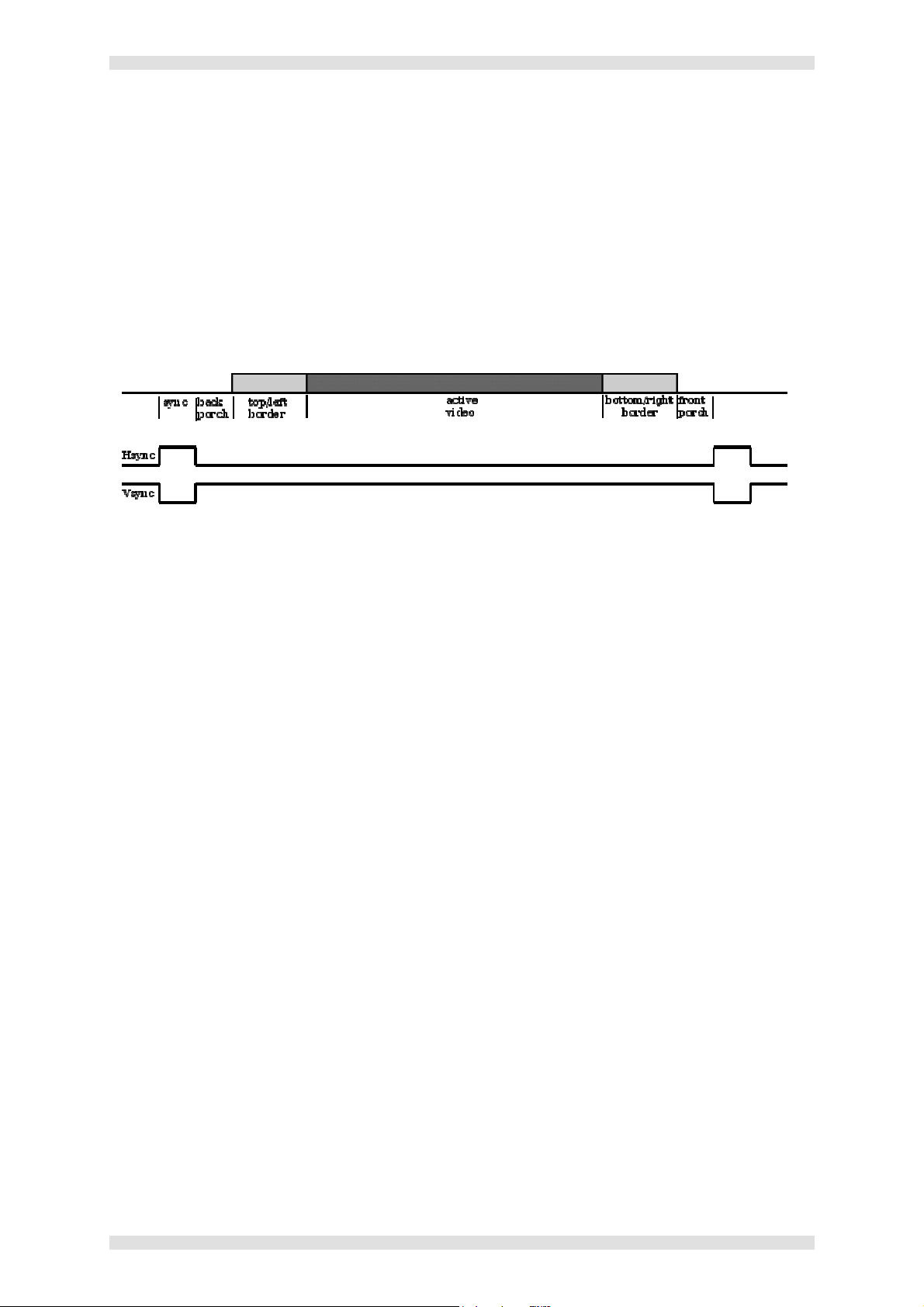
VN-MATRIX User Guide Section 4: Advanced Setup Procedures
The Cloning Method
An existing video format is cloned by selecting an existing format from the Name list box then clicking
on New Format. A popup dialog will then prompt for a new name. This should be descriptive and
ideally include the resolution and frame rate. Once a user video format has been created the various
timing fields can be edited. New values are typed into the appropriate fields and pressed to commit
the change.
The following graphic indicates the meaning of each term. Only the active video area contains visible
content. The borders are normally on screen but do not show content. The two porches and the sync
together define the 'screen blanking'. This is a non-visible portion of the signal inserted to give a CRT
sufficient time to reset to the start of the next line/frame.
The following relationships must hold:
• TotalPixels = ActivePixels + LeftBorder + RightBorder + HorFrontPorch + HorSync +
HorBackPorch
• TotalLines = ActiveLines + TopBorder + BottomBorder + VertFrontPorch + VertSync +
VertBackPorch
• PixelClock = TotalPixels * TotalLines * FrameRate
• Borders (margins) are typically only used for VGA sized modes
NOTE: It is difficult to create a video format that will be correctly interpreted by monitors without
adhering quite closely to standards. If definitive timing information is not available it is suggested the
following CVT/GTF approach is used.
NOTE: Interlace modes cannot be created by this or the CVT/GTF method at this time.
After a suitable video format has been created and tested it can be saved to non-volatile storage by
clicking on Save Formats. This video format will then be available after a device reset or power cycle.
Unwanted user video formats can be deleted by selecting the video format to delete and clicking on
Delete. A Save Formats operation is then required to delete this format from non-volatile storage.
I458GB issue 6 Page 79
Page 80

Section 4: Advanced Setup Procedures VN-MATRIX User Guide
The CVT/GTF Method
GTF and the newer CVT are a standardized approach to creating video formats.
To select a GTF format the user must input Active Pixels, Active Lines, Frame Rate and the margins
flag, then click the GTF button . All other fields will then be filled in with the nearest suitable GTF video
format.
A CVT video format is similarly selected. However CVT also supports the reduced blanking flag.
Reduced blanking allows LCD panels, which do not require as long a blanking period as CRTs, to
support a higher resolution for any fixed maximum pixel clock rate.
After a suitable video format has been created and tested it can be saved to non-volatile storage by
clicking on Save Formats. This video format will then be available after a device reset or power cycle.
Unwanted user video formats can be deleted by selecting the video format to delete and clicking on
Delete. A Save Formats operation is then required to delete this format from non-volatile storage.
Page 80 I458GB issue 6
Page 81

VN-MATRIX User Guide Section 4: Advanced Setup Procedures
System Set Up
Changing User Login Passwords
Login to the Web Interface (see page 41).
From the Device List page click the Accounts tab.
The following page will appear:
VN-MATRIX has two user accounts:
admin – which allows full read/write access to all setup parameters,
public – which allows read only access to setup parameters.
Enter the Current Password for the user account you want to change.
Then enter the new password in both the New Password and Confirm fields.
NOTE: The password can include letters, numbers and the underscore character, and is case-
sensitive.
Click the Update button to save the change. The new password will be required the next time you
login.
I458GB issue 6 Page 81
Page 82

Section 4: Advanced Setup Procedures VN-MATRIX User Guide
Upgrading Device Firmware
From time to time Electrosonic may issue firmware upgrades for VN-MATRIX, in order to make new
functionality available. Details if the latest firmware release will be published on our website.
Upgrades are supplied in a single file, named in the format ‘upgrade_ver3.3c.tar’ where ‘ver3.3c’ is
the version number. Before you start you will need to copy the upgrade file on to the computer that
you use to access the VN-MATRIX controller.
The update process is split into the following stages:
Stage Function Summary Performed On
UPLOAD
Copy the upgrade file from the control PC to a
The VN-MATRIX Controller only
temporary storage area on the VN-MATRIX
Controller
PREPARE
Unpack and copy the new firmware (from the
controller) into the VN-MATRIX alternate flash
Each VN-MATRIX device
including the controller
memory.
ACTIVATE
Reboot the VN-MATRIX to start using the new
firmware. This is a temporary mode that allows
Each VN-MATRIX device
including the controller
you to test the new firmware. If you encounter
any problems you can ‘back out’ of this mode
and return to the previous firmware version.
COMMIT
Reboot the VN-MATRIX to start using the new
firmware permanently.
Each VN-MATRIX device
including the controller
All stages of the upgrade process are carried out using the Web Interface. It is recommended that all
VN-MATRIX units in the same system are upgraded to the same firmware version to ensure full
compatibility.
IMPORTANT NOTES:
• Performing the ACTIVATE function on the controller will cause the device to reboot and as a
result the upgrade file (in the temporary storage are) will be erased. It is recommended,
therefore, that you PREPARE all
devices first, after which the upgrade file will no longer be
needed. Then perform the ACTIVATE function on each device, commencing with the
controller.
• The ACTIVATE function must be performed on the controller device first
, such that the new
firmware is in control of upgrading the remaining devices.
• When performing ACTIVATE or COMMIT on the controller, the device will reboot.
This will cause temporary loss of the Web Interface, since this is provided by the controller.
Wait for 30 seconds to allow the device time to reboot, then ‘refresh’ the browser.
Page 82 I458GB issue 6
Page 83

VN-MATRIX User Guide Section 4: Advanced Setup Procedures
To upload the firmware file to the VN-MATRIX controller…
Login to the Web Interface (see page 41).
From the Device List page click on the VN-MATRIX controller device.
From the Device page click the Upgrade tab. The Upgrade page will appear:
This is the existing firmware version.
This is the version you will be upgrading to.
Click the Browse button to navigate to the required upgrade file, or type the path and filename
directly into the field provided.
Click the Upload button to begin uploading the file to the VN-MATRIX controller. This may take a
few minutes.
Once the file is uploaded, you can begin installing it into each unit (as described on page 84)
starting with the controller unit.
I458GB issue 6 Page 83
Page 84

Section 4: Advanced Setup Procedures VN-MATRIX User Guide
To install the new firmware into each VN-MATRIX unit…
IMPORTANT NOTE: You must upgrade the VN-MATRIX controller first. Please note, however, that
once you go past the READY TO ACTIVATE stage the unit will reboot and the upgrade file will be
erased from the controller. It is recommended, therefore, that you get ALL devices to the READY TO
ACTIVATE stage before completing the controller upgrade, otherwise you will need to upload the file
again (as described on page 83).
From the Device List page click on the VN-MATRIX unit that you want to upgrade.
From the Device page click the Upgrade tab. The Upgrade page will appear.
Click the Select Firmware Version listbox and choose the new firmware file you want to install.
Usually there will only be one file listed (i.e. the file that you uploaded using the procedure on
page 83).
The remainder of the installation procedure is achieved using the forward and (if necessary) reverse
buttons, to move the installation between the various stages. The current stage/status is indicated by
the Device Upgrade Status field.
The process allows you to temporarily install and test the new firmware and, if everything is OK, you
can then permanently install (commit) the new firmware. Up until the last stage it is possible to return
to the existing firmware version.
The process is summarized in the following diagram:
Click the forward button. The Device Upgrade Status field will show PREPARE and percentage
progress. This stage may last a few minutes.
HINT: The chosen firmware version is confirmed in the Upgrade Version field.
When READY TO ACTIVATE appears, click the forward button again.
The unit will then reboot. Once rebooted the Device Upgrade Status field will show READY TO
COMMIT and the VN-MATRIX will be using the new firmware. Test for correct operation.
If everything is working correctly, click forward again to permanently install the new firmware. The
Device Upgrade Status field will show COMMITING and percentage progress. This stage may
last a few minutes.
If you experience any problems, click reverse to return to the previous stage.
When the Device Upgrade Status field returns to WAIT the unit is ready for use.
Page 84 I458GB issue 6
Page 85

VN-MATRIX User Guide Section 4: Advanced Setup Procedures
Changing a Device Licence
Each VN-Matrix unit is supplied with a default level of functionality which can be upgraded by
obtaining a special license key from Electrosonic.
A license key comprises two elements – a ‘structure’ and a ‘checksum’. These are entered using the
License page which is accessed via the license management button on the Device page:
Enter the New Structure and New Checksum information exactly as supplied.
Click the Update Licence button.
I458GB issue 6 Page 85
Page 86

Section 5: Serial Transport & Control Methods VN-MATRIX User Guide
SECTION 5:
Serial Transport & Control Methods
Page 86 I458GB issue 6
Page 87

VN-MATRIX User Guide Section 5: Serial Transport & Control Methods
oth units are set to serial Server mode
Overview
Routing of external serial (RS-232) communications can be achieved between any VN-MATRIX units
on the same network.
Serial traffic can be unidirectional as part of a source stream (encoder to decoder) – Data Stream
Mode - or bi-directional and independent of any source stream – Passthrough Mode.
In addition, serial commands can be sent via any VN-MATRIX device to the VN-MATRIX controller,
allowing dynamic control of system parameters – Remote Control Mode.
Data Stream Mode
In this mode, data received by an encoder is transported to the decoder, along with video and audio,
as part of the source stream. Data transport in this mode is unidirectional and is capable of being
recorded (and played back) by VN-RECORDER.
VN-MATRIX VN-MATRIX
(encoder) (decoder)
Data input to the encoder is sent to the
decoder as part of the source stream
along with video and audio
B
NETWORK
TCP RS-232RS-232 TCP
Serial ports on each VN-MATRIX need not share a common baud rate. However, where a large
amount of data is sent from a high speed to a low speed data link, some form of handshaking/flow
control may be required to prevent buffer overflow on the output device. Standard flow control
methods are fully supported.
IMPORTANT: No data will be transported until the decoder ‘connects’ to the encoder stream.
To set up a serial data stream, see page 90.
I458GB issue 6 Page 87
Page 88

Section 5: Serial Transport & Control Methods VN-MATRIX User Guide
Passthrough Mode
In this mode, data received by a device ‘input’ is transmitted using TCP/IP over the network and then
converted back to serial data by a device ‘output’. Data flow is fully bi-directional and totally
independent of whether a VN-MATRIX is configured as an encoder or decoder.
One device within a passthrough group is designated as a server. One or more devices are then
‘connected’ as clients (in passthrough mode):
Serial ports on each VN-MATRIX need not share a common baud rate. However, where a large
amount of data is sent from a high speed to a low speed data link, some form of handshaking/flow
control may be required to prevent buffer overflow on the output device. Standard flow control
methods are fully supported.
Any number of serial passthrough groups may exist on the same network.
To set up a serial passthrough group, see page 91.
Page 88 I458GB issue 6
Page 89

VN-MATRIX User Guide Section 5: Serial Transport & Control Methods
Remote Control Mode
In addition to ‘passthrough’ operation outlined above, a VN-MATRIX serial input can be configured to
communicate directly with the VN-MATRIX controller. This provides basic serial ‘remote control’
functionality of a VN-MATRIX system, such as display source switching. A full list of serial commands
can be found on page 93.
One or more devices are designated as clients (in remote control mode). Data received by a device
‘input’ is then automatically transmitted using TCP/IP over the network to the VN-MATRIX controller:
Serial remote control functionality is totally independent of whether a VN-MATRIX is configured as an
encoder or decoder.
To set up a remote control group, see page 92.
I458GB issue 6 Page 89
Page 90

Section 5: Serial Transport & Control Methods VN-MATRIX User Guide
Setting-up a Serial Data Stream
Login to the Web Interface (see page 41).
From the Device List page click on the required encoder device.
From the Device page click the Serial tab to display the following:
Using the mode listbox select the server option.
Change the other settings (e.g. baud rate) as required, then click the Save tab.
Return to the Device List and do the same for the decoder device.
IMPORTANT: No data will be transported until the decoder ‘connects’ to the encoder stream.
Page 90 I458GB issue 6
Page 91

VN-MATRIX User Guide Section 5: Serial Transport & Control Methods
Setting-up a Serial Passthrough Group
Decide which VN-MATRIX unit is to be the server in the passthrough group and which will be the
client(s), and connect your serial devices to the VN-MATRIX COM2 ports accordingly.
Remember, communication can only take place between server and client(s), not between clients.
Login to the Web Interface (see page 41).
From the Device List page click on the device you want to configure as the server.
From the Device page click the Serial tab to display the following:
Using the mode listbox select the server option.
Change the other settings (e.g. baud rate) as required, then click the Save tab.
Then, for each
Return to the Device List page (by clicking on the Device List tab).
Click on the device you want to configure as a client, then click the Serial tab.
Using the mode listbox select the client option (note that this will reveal the destination box).
Using the destination listbox select passthrough for the appropriate server.
Change the other settings (e.g. baud rate) as required, then click the Save tab.
client in the group…
I458GB issue 6 Page 91
Page 92

Section 5: Serial Transport & Control Methods VN-MATRIX User Guide
Setting-up a Remote Control Group
Decide which VN-MATRIX unit(s) will act as the remote control client(s) and connect your serial
control device(s) to the VN-MATRIX COM2 port(s) accordingly.
Login to the Web Interface (see page 41).
From the Device List page click on the device you want to configure as a remote control client.
From the Device page click the Serial tab to display the following:
Using the mode listbox select the client option.
Using the destination listbox select the remote-control option.
Change the other settings (e.g. baud rate) as required, then click the Save tab.
Page 92 I458GB issue 6
Page 93

VN-MATRIX User Guide Section 5: Serial Transport & Control Methods
Serial / Telnet Commands
The following commands can be used to provide basic remote control of a VN-MATRIX system.
Commands can be issued either as part of a serial remote control configuration (see page 89) or by
using a Telnet application via the network (see page 106).
In either case, a control session must first be initiated by sending a valid username and password.
All commands must be terminated (actioned) with a ‘new line’ character (carriage return not required).
In programs such as Telnet, this is accomplished by pressing the Enter key.
Control Session Commands
user <username>
Initiates a user login. To be able to change system settings you must login using the
‘admin’ user account.
EXAMPLE: user admin
pass <password>
Specifies the password for the user account. By default this will be ‘admin’ but may have
been changed using the Web Interface (see page 81).
EXAMPLE: pass admin
exit
Terminates the current remote control session.
I458GB issue 6 Page 93
Page 94

Section 5: Serial Transport & Control Methods VN-MATRIX User Guide
Device Commands
mode <deviceid> <state>
Changes the operating mode of the specified device.
<deviceid> is the device serial number of the device or the user-defined device name.
<state> is the required mode and can be set to:
enable – for normal operation
disable – to stop encoder source streaming or stop display output on a decoder
standby – to stop encoder source streaming or display splash screen on a decoder
EXAMPLE: mode 16 enable
channel <deviceid> <window> <sourceid.videoport.protocol>
Changes the source being displayed in a window of the specified decoder device.
<deviceid> is the device serial number of the device or the user-defined device name.
<window> is the window object number. Currently this can only be 0.
<sourceid.videoport.protocol> is the source to be displayed, where:
source id is the serial number of the source device,
videoport is the video input number, usually set to 0,
protocol specifies either RTP or TCP, set to 0 for RTP or 1 for TCP.
NOTE: Full stops (.) are required between the sourceid, videoport and protocol values.
EXAMPLE: channel 17 0 16.0.1
optimization <deviceid> <videoport> <mode>
Changes the compression transform for the specified encoder device.
<deviceid> is the device serial number of the device or the user-defined device name.
<videoport> is the video input number, usually set to 0.
<mode> is the source transform to be used and can be set to:
video – for video sources
graphics – for graphics sources
EXAMPLE: optimization 16 0 video
bandwidth <deviceid> <videoport> <bandwidth>
Changes the target bandwidth value for the specified encoder device.
<deviceid> is the device serial number of the device or the user-defined device name.
<videoport> is the video input number, usually set to 0.
<bandwidth> is the bandwidth value in Megabits per second.
EXAMPLE: bandwidth 16 0 5
Page 94 I458GB issue 6
Page 95

VN-MATRIX User Guide Section 5: Serial Transport & Control Methods
Response Messages
All commands (except for user and exit) will generate an ok response message if the command is
successfully executed.
Unrecognized commands or invalid command parameters will generate an error message in the
format fail: followed by a brief description of the error, for example fail: unknown command.
I458GB issue 6 Page 95
Page 96

Section 6: Remote Keyboard & Mouse Operation VN-MATRIX User Guide
SECTION 6:
Remote Keyboard & Mouse Operation
Page 96 I458GB issue 6
Page 97

VN-MATRIX User Guide Section 6: Remote Keyboard & Mouse Operation
Overview
When a PC source is being viewed by a VN-MATRIX decoder, remote keyboard and mouse control of
the source PC can be achieved via the decoder unit.
For remote keyboard and mouse functionality to be possible:
The keyboard and mouse ports of the source PC must be fully connected to the VN-MATRIX
encoder (as shown on page 37 or 38),
A keyboard and mouse must be connected to the VN-MATRIX decoder
(as shown on page 39 or 40), and
The decoder must currently be viewing the PC source.
To initiate a remote control session…
Using the keyboard attached to the VN-MATRIX decoder, press the Scroll Lock key twice,
followed by the F1 key.
The source monitor will briefly show
MK:Remote in the top left-hand
corner…
MK:Remote MK:Forward
The display monitor will briefly show
MK:Forward in the top left-hand
corner…
MK:ForwardMK:Remote
NOTE: Local keyboard and mouse control of the source will be disabled. See below for instructions on
regaining local control.
To terminate a remote control session…
Using the keyboard attached to the VN-MATRIX decoder or encoder, press the Scroll Lock key
twice, followed by the F2 key.
Both the source monitor and display monitor will briefly show MK:Local in the
top left-hand corner…
MK:Local MK:Local
MK:LocalMK:Local
I458GB issue 6 Page 97
Page 98

Section 7: Technical Data VN-MATRIX User Guide
SECTION 7:
Technical Data
Page 98 I458GB issue 6
Page 99

VN-MATRIX User Guide Section 7: Technical Data
VN-MATRIX Hardware
Mechanical Data
Overall Dimensions: Width: 215mm (8.47 inches)
Depth: 308mm (12.17 inches) [including rear sockets]
Height: 44mm (1.74 inches) [excluding feet]
53mm (2.09 inches) [including feet]
Average Weight: 1.4 kg (3.1 lbs)
Operating Conditions
Ambient Temperature: 5°C to 35°C (41°F to 95°F).
Ambient Humidity: 85% maximum (non-condensing).
Location: Free-standing or 19” Rack-mounting (using approved kit).
Cooling Method: Internal fan (temperature controlled speed).
Power Supply
VN-MATRIX
Supply Voltage: 12V DC Regulated (via Mains Adapter)
Supply Current: 6A max.
MAINS ADAPTER
Supply Voltage: 100 – 240V AC nominal.
Supply Frequency: 50 – 60 Hz nominal.
Supply Current: 0.45A maximum.
Supply Inlet Connector: IEC320 (C14).
Supply Mating Connector: IEC320 (C13); suitable 2m (6ft) mains cord supplied.
I458GB issue 6 Page 99
Page 100

Section 7: Technical Data VN-MATRIX User Guide
Connectors
Keyboard/Mouse (PS/2)
Function: Keyboard and mouse pass-through connections for source computer.
Connector Type: 6-pin mini-DIN (female)
Pin-out Details:
Pin Function
1 Data
2 No connection
3 Ground
4 +5V supply*
5 Clock
6 No connection
* 5V on pin 4 limited to 200mA by thermal fuse.
Mating Connector: 6-pin mini-DIN (male).
Recommended Cable: Supplied screened PS/2 cable.
Max. Cable Length: 2.95 metres (9.5 feet).
Digital Audio I/O (SPDIF IN and OUT)
Function: Input and Output/Loop-Through for digital audio.
Connector Type: RCA Phono Socket
Mating Connector: RCA Screened Phono Plug
Recommended Cable:
Max. Cable Length: 10 metres (32 feet)
75Ω co-axial.
Page 100 I458GB issue 6
 Loading...