

Page 1
Page 2

Page 3

USER GUIDE
Page 4

VN-COMMANDER AND VN-COMMANDER CONNECT USER GUIDE
(QUANTUM EDITION) Part No. I456GB issue 8 (August 2009)
Copyright © 2009 Electrosonic Ltd.
All rights reserved.
No part of this documentation may be reproduced or transmitted in any form or by any means,
electronic or mechanical, including photocopying and recording, without the prior written
permission of Electrosonic Ltd.
The information in this documentation is supplied without warranty of any kind, either directly
or indirectly, and is subject to change without prior written notice. Electrosonic, its employees or
appointed representatives will not be held responsible for any damages to software, hardware, or
data, howsoever arising as a direct or indirect result of the product(s) mentioned herein.
Issued by:
Product Support,
Electrosonic Ltd.,
Hawley Mill,
Hawley Road,
Dartford,
Kent,
DA2 7SY,
United Kingdom.
Documentation written and designed by Andrew M. Bailey.
Printed in the United Kingdom.
Page 5

VN-COMMANDER User Guide Preface
Preface
About This User Guide This is a User Guide for the VN-COMMANDER and VN-
COMMANDER CONNECT software applications from
Electrosonic. This User guide provides information for the
following Electrosonic products
- VN-Quantum
- VN-Quantum Connect
To help you to quickly locate the information you require,
it is structured into four main sections:
•••• Section 1: Getting Started — which explains how to
install the software and image processing hardware,
as well as introducing the user interface and some
basic ‘housekeeping’ procedures;
•••• Section 2: System Configuration — which gives
details on setting up VN-COMMANDER to control
VN-QUANTUM image processing hardware;
•••• Section 3: Creating a Presentation — which explains
how to manipulate sources on the target display;
•••• Section 4: Viewing a Presentation — which explains
the diff eren t me thod s you can use to view a
VN-COMMANDER presentation;
•••• Appendix A: IP Addressing — which briefly explains
what IP Addresses are and how to decide on suitable
addresses for your system.
•••• Appendix B: Serial Commands — which gives advice on
the formatting and usage of serial data strings for
controlling serial switchers and other RS-232 devices.
•••• Appendix C: Access Control — which describes the
built-in access control functionality, allowing different
users to have different access rights.
A summary contents list is provided at the start of each
section and a full contents list appears after this preface.
I456GB issue 8
- iii -
Page 6

Preface VN-COMMANDER User Guide
Firmware & Software
Versions
The features and functionality described in this User
Guide are based on VN-COMMANDER & VNCOMMANDER Connect control software v1.5f used with
VN-QUANTUM firmware v6.xx and later.
For the latest details on new firmware and software
releases, please visit the Product Support Area of our
Web site — http://www.electrosonic.com/technical-
support-0., or contact your Electrosonic Support
Representative for further details.
Trademarks VISIONETWORK
GLIMPSETM, VN-COMMANDERTM, ELECTROSONICTM,
TM
ES
and the
ELECTROSONIC
trademarks of ELECTROSONIC LTD.
WINDOWS® is a registered trademark of MICROSOFT
CORPORATION.
All other brand and product names are trademarks or
registered trademarks of their respective holders.
TM
, VN-QUANTUMTM, VN-
TM
logo are registered
iv
I456GB issue 8
Page 7

VN-COMMANDER User Guide Contents
2
What is VN
-
COMMANDER?
..........................
2
Hardware Requirements
................................
3
Software Installation
................................
.... 4
Hardware Configuration
..............................
6
Connection to a VN
-
QUANTUM Processor
.........
7
Configuring the Computer’s IP Address
..............
8
Testing the Ethernet Link
...............................
12
Running and Exiting VN
-
COMMANDER
...... 14
The Main
Application Window
.....................
15
Starting a New Presentation
............................
17
Loading an Existing Presentation
......................
18
Saving a Presentation
................................
... 18
19
Choosing a Display Processor
.........................
24
Choosing a Display Layout
...............................
26
Target Display Clock
................................
...........
34
Communications Setup
................................
.... 36
Set Up Sources
................................
.................
43
The Set Up Sources Task
................................
.... 44
69
Working with Scenes
................................
........
71
Contents
Section 1:
Section 2:
Getting Started
Introduction.................................................
Using the Auto-Backup Function......................
System Configuration
Introduction ...................................................... 23
Section 3:
I456GB issue 8
Source Parameters............................................ 50
Creating a Presentation
Introduction ......................................................
Creating a New Scene........................................ 71
- v -
Page 8

VN-COMMANDER User Guide Contents
Adding or
Changing Scene Commands
...........
74
Copying an Existing Scene
...........................
77
Changing the Order of Scenes
.......................
77
Scene Navigation
................................
.......
78
Deleting a Scene
................................
........
78
Adding a Window to a Scene
.........................
81
Removing a Window from a Scene
.................
81
Choosing the Window Sou
rce
.......................
82
Choosing the Window Style
..........................
83
Changing a Source Viewport
.........................
87
Moving and Resizing a Window
.....................
90
Changing the Layer of a Window
....................
93
95
Changing the Properties of a Scene.................
73
Working with Windows.................................
Changing the Virtual Display Properties.............
Section 4: Viewing a Presentation
Introduction........................................................ 99
Using the Scene Controller .............................. 100
Overview of the Scene Controller........................... 101
Full Screen Mode...............................................102
Creating a Default Layout......................................104
Customizing the Layout........................................105
Using the Bitmap Manager....................................111
Using The AutoPlay Facility............................. 114
Changing the Order of Scenes...............................114
Changing the Display Time for a Scene....................116
Starting and Stopping the Presentation.................... 116
Changing the Playback Speed...............................117
79
I456GB issue 8
vi
Page 9

VN-COMMANDER User Guide Contents
Appendix A: IP Addressing
What is an IP Address?....................................................119
Choosing IP Addresses......................................120
Appendix B: Serial Commands
Introduction......................................................123
Control of External Devices..............................124
Format of External Control Strings
Examples of External Control Strings
................................. 125
.......................... 126
Remote Control of a Presentation.....................127
R-type Message Format.....................................128
Examples of R-type Messages ............................ 133
ASCII Character Chart ......................................137
Appendix C: Access Control
Overview................................................................................139
Log-In Procedure.................................................................140
Enabling/Disabling Access Control.................................. 141
Changing Role Passwords................................................142
I456GB issue 8
vii
Page 10

VN-COMMANDER User Guide Contents
I456GB issue 8
- viii -
Page 11

Introduction
................................
.2
Secti on 1:
G e t t i n g S t a r t e d
•
What is VN-COMMANDER?............... 2
•
Hardware Requirements..................... 3
Software Installation ................... 4
Hardware Configuration.............. 6
•
Connection to a VN Processor ............. 7
•
Configuring the Computer’s IP Address 8
•
Testing the Ethernet Link.................. 12
R u n n i n g a n d E x i t i n g
VN-COMMANDER ..................... 14
The Main Application Window . 15
•
Starting a New Presentation.............. 17
•
Loading an Existing Presentation ...... 18
•
Saving a Presentation ..................... 18
•
Using the Auto-Backup Function........ 19
Page 12

Section 1: Getting Started VN-COMMANDER User Guide
Introduction
What is VN-COMMANDER?
VN-COMMANDER and VN-COMMANDER CONNECT
are Microsoft Windows-based software applications, used
to control the VN-QUANTUM and VN-QUANTUM
CONNECT Image Display Processors. These products
form part of the VISIONETWORK (VN) range.
Under VN-COMMANDER control, the VN-QUANTUM and
VN-QUANTUM CONNECT Processors can display multiple
image sources on a target display. External analog video
sources (e.g. PAL, NTSC or SECAM formats) and external
analog and digital graphics sources are supported. In
addition, the VN-QUANTUM processor supports the use of
internal or network-based image files (e.g. BMP, JPG, GIF or
PNG formats) or RGB computer graphics captured using
Electrosonic’s VN-GLIMPSE technology.
For clarity, the term VN-COMMANDER and VNQUANTUM will be used throughout this User guide and
are interchangeable with VN-QUANTUM CONNECT and
VN-COMMANDER CONNECT.
The feature set supported by VN-COMMANDER and VNCOMMANDER CONNECT are slightly different. This user
guide covers both software applications. Where features
differ, this will be made clear.
VN-COMMANDER will not operate with a VNQUANTUM-CONNECT processor.
VN-COMMANDER CONNECT will not operate with a
VN-QUANTUM processor.
2 - I456GB issue 8
Page 13
VN-COMMANDER User Guide Section 1: Getting Started
Scene Control Each source is displayed in a fully resizable ‘window’,
allowing multiple sources to be placed in any position on
the display.
VN-COMMANDER uses ‘scenes’ to record different
source layouts on the display. Scenes can then be recalled
in any order using a customizable user interface or in a
pre-defined order at specific time intervals using the
built-in AutoPlay function.
Scenes can also be recalled remotely using via RS-232 (see
Appendix B) or Ethernet (consult Electrosonic for details).
Co nt ro l of
External Devices
VN-COMMANDER can be set up to include commands
which are transmitted (over serial or Ethernet links) when
a particular scene or source is selected. These commands
can be used to provide automatic control of external
devices such as disc players or matrix switchers.
Hardware Requirements
Computer
Specification
To ensure that VN-COMMANDER functions correctly
and reliably, it must be installed on a computer that meets
or exceeds the following criteria:
Operating System Windows NT4 (SP6) Windows 2000/ XP
Processor Speed 200MHz 450MHz or higher
Memory (RAM) 64MB 128MB or higher
Hard Disk Free Space 30MB >30MB
Graphics 1024x768, 65K colors (16-bit) 1024x768, 16.7M colors (32-bit)
Network Card (Ethernet) 10BASE-T 100BASE-T
Minimum Recommended
These are the minimum requirements for VN-COMMANDER
only; if you intend running additional software applications,
these applications may require a higher specification.
I456GB issue 8 3
Page 14

Section 1: Getting Started VN-COMMANDER User Guide
Image Processing
Hardware
VN-COMMANDER is designed to be used in
conjunction with a VN-QUANTUM Image Display
Processor.
The VN-QUANTUM hardware comprises a card
frame into which various input/output cards are
installed.
For further details on the VN-QUANTUM, including
connector pin-outs and processing capability, please
refer to the VN-QUANTUM User Guide (part no.
I455GB).
Except for defining an IP Address, it is not necessary to
perform any set-up procedures using the VN-
QUANTUM itself. All other system configuration
is achieved through VN-COMMANDER.
Software Installation
~
Insert the VN-QUANTUM System Disc into the
CD-ROM drive on the computer.
After afew seconds a disc browser should
automatically start.
~
Choose the Install option in the VN-COMMANDER
section. The on-screen instructions will guide you
through the rest of the installation process.
If the disc browser does not run automatically or if you have the
Windows auto-play feature disabled, proceed as follows:
4 - I456GB issue 8
Page 15

VN-COMMANDER User Guide Section 1: Getting Started
~
Click on the Windows Start button, and select Run from the pop-up menu.
The Run dialog box will appear.
~
In the Open box, type in the following command:
d :\setup.exe
where ‘d’ is the letter identifying your CD-ROM drive.
~
Click on the OK button (or press the Enter key) to run the disc browser.
I456GB issue 8 5
Page 16

Section 1: Getting Started VN-COMMANDER User Guide
Hardware Configuration
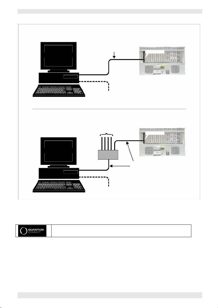
Connection to a VN-QUANTUM Processor
The VN-COMMANDER computer communicates with a
VN-QUANTUM via an Ethernet link. This can either be
‘direct’ or ‘indirect’ as shown in Fig.1. Connection to a
single processor can use either method, but multiple
processors must use the indirect method (i.e. via a hub).
Direct Connection This method uses a single cable is connected between the
computer’s Network port and the VN-QUANTUM (see
Fig.1a). The cable must be a ‘crossover’ (or ‘null modem’)
type; a normal ‘straight-through’ cable will not work.
The computer’s Network port must be capable of
supporting a 100BASE-T connection as required by the
VN-QUANTUM.
Indirect Connection With this method (see Fig.1b) the connection is made via
a hub, switcher or local area network (LAN). Normal
‘straight-through’ type cables must be used;
a ‘crossover’ (or ‘null modem’) cable will not work.
The hub or switcher connected to the VN Processor must
be capable of supporting a 100BASE-T connection as
required by the VN-QUANTUM.
Ethernet Cables Electrosonic recommends that you use only Category 5
shielded (STP) cables. Suitable cables are readily available
from most computer stores.
A 5 metre (16 feet) ‘crossover’ type cable is supplied with
the VN-QUANTUM Processor. This can also be ordered
separately under part number ES5960.
For further details on cable requirements and connector pin-outs, please
refer to the Technical Data section of the VN-QUANTUM User Guide.
6 I456GB issue 8
Page 17
VN-COMMANDER User Guide Section 1: Getting Started
a) Direct’ Connection
c) Indirect’ Connection
VN-COMMANDER
VN-COMMANDER
other VN
-
QUANTUM P
rocessors
RS-232
RS-232
Ethernet
Ethernet
This must be a ‘Crossover’
Optional RS
-
232 link to
Optional RS
-
232 link to
HUB
These
must be standard
VN-QUANTUM
VN-QUANTUM
(or ‘Null Modem’) type cable
100B ASE-T
control source switchers
CONTRO L Port
PROCESSOR
Fig.1: Methods of connecting the
VN-QUANTUM CONNECT is available as a 4U frame.
or network sources/devices
100B ASE-T
control source switchers
VN-COMMANDER
CONTRO L Port
PROCESSOR
‘Straight Through’ type cables
(i.e. not ‘Crossover’ types)
computer to a
VN-QUAN TU M.
I456GB issue 8 7
Page 18

Section 1: Getting Started VN-COMMANDER User Guide
Configuring the Computer’s IP Address
The computer’s Network port must be configured to use th e
s a m e c o mm u ni c ati o ns p r o to c o l a s t h e VNQUANTUM (called TCP/IP). It must also be allocated an
IP Address that is compatible with the VN Processor. For
advice on choosing IP Addresses, see Appendix A.
If the computer is already connected to (and configured for)
an existing network, you must consult the network
administrator before making any of the following
changes. In addition, please note that you will need to be
logged on with administrative rights before you can change
Windows network settings.
8 I456GB issue 8
Page 19

VN-COMMANDER User Guide Section 1: Getting Started
~
Setting the IP Address
(Windows XP)
Click the windows Start button and right-click on the
My Network Places icon.
~
From the popup menu that appears choose
Properties.
The Network Connections window will appear.
~
Right-click on the Local Area Connection icon.
~
From the popup menu that appears choose Properties.
The Local Area Connection Properties dialog box will appear.
~
In the list of loaded components double-click on the
Internet Protocol (TCP/IP) entry.
The Internet Protocol (TCP/IP) Properties dialog box will appear.
~
Click on the 'Use the following IP address' option
and type-in the required IP Address and Subnet Mask.
HINT: Remember that you can, if preferred, change the IP Address
of the VN-QUANTUM Processor to suit that of the computer.
For further information and advice on choosing these values,
refer to ‘Appendix A – IP Addressing’.
~
Click on the OK button to action the changes (or
Cancel to retain the existing settings).
~
Restart the computer to implement the new settings.
I456GB issue 8 9
Page 20

Section 1: Getting Started VN-COMMANDER User Guide
Setting the IP Address
(Windows 2000)
~
Right-click on the My Network Places icon on the
Windows desktop.
~
From the popup menu that appears choose
Properties.
The Network & Dial-up Connections window will appear.
~
Right-click on the Local Area Connection icon.
~
From the popup menu that appears choose Properties.
The Local Area Connection Properties dialog box will
appear.
~
In the list of loaded components double-click on the
Internet Protocol (TCP/IP) entry.
The Internet Protocol (TCP/IP) Properties will appear.
~
Click on the 'Use the following IP address' option
and type-in the required IP Address and Subnet
Mask.
HINT: Remember that you can, if preferred, change the IP
Address of the VN-QUANTUM Processor to suit that of
the computer.
For further information and advice on choosing these
values, refer to ‘Appendix A – IP Addressing’.
~
Click on the OK button to action the changes (or
Cancel to retain the existing settings).
~
Restart the computer to implement the new settings.
10 I456GB issue 8
Page 21

VN-COMMANDER User Guide Section 1: Getting Started
Setting the IP Address
(Windows NT)
~
Right-click on the Network Neighborhood icon on
the Windows desktop.
~
From the popup menu that appears choose Properties.
The Network dialog box will appear.
~
Select the Protocols tab then, in the Network
Protocols list, double-click the TCP/IP Protocol.
The TCP/IP Properties dialog box will appear.
~
Select the IP Address tab, click on the 'Specify an IP
address' option and type-in the required IP Address
and Subnet Mask.
HINT: Remember that you can, if preferred, change the IP
Address of the VN-QUANTUM Processor to suit that of
the computer.
For further information and advice on choosing these
values, refer to ‘Appendix A – IP Addressing’.
~
Click on the OK button to action the changes (or
Cancel to retain the existing settings).
~
Restart the computer to implement the new settings.
I456GB issue 8 11
Page 22

Section 1: Getting Started VN-COMMANDER User Guide
Testing the Ethernet Link
Using the ‘Ping’ Utility
To test the operation of the Ethernet link between the
computer and a VN-QUANTUM Processor, you can use
the ‘Ping’ utility supplied with Windows NT/2000/XP.
~
Click on the Windows Start button, and select Run
from the pop-up menu.
The Run dialog box will appear.
~
In the Open box type in the following command:
ping xxx.xxx.xxx.xxx –t
where xxx.xxx.xxx.xxx is the IP Address of the VN
Processor that you want to test.
~
Click on the OK button or press the Enter key.
A text box will appear showing a series of messages;
these are explained on page 13.
~
To stop the ping utility, press Ctrl + C on the
keyboard.
12 I456GB issue 8
Page 23

VN-COMMANDER User Guide Section 1: Getting Started
‘Ping’ Utility
Response Messages
When you run the Ping utility, it will display a series of
response messages, which you can use to determine the state of
the communications link.
For example, if you have ‘pinged’ a VN Processor with
the address 208.132.180.48, you should get a message
similar to the following:
Reply from 208.132.180.48: bytes=32 time=2ms TTL=32
This is the correct response which indicates that the
device at the specified address is communicating
correctly. Note that the response ‘time’ value may vary
according to network traffic.
If you get the message...
Request timed out.
...this indicates that there has been no response from the
specified address. Either the processor is not
receiving data from the computer or not sending data
back. Check that the VN Processor is powered-up and set
to the same address that you ‘pinged’. Also, check that
you are using the correct type of connecting cables (i.e.
straight through or crossover – see pages 6 & 7) and that
they are not damaged or faulty.
I456GB issue 8
If you get the message...
Reply from 208.132.180.48: Destination host unreachable.
this indicates that the IP Address of the computer is not
in the same ‘class’ as that of the VN Processor. See
‘Appendix A – IP Addressing’ for further advice.
11
Page 24

Section 1: Getting Started VN-COMMANDER User Guide
Running and Exiting VN.COMMANDER
Running
VN.COMMANDER
Exiting
VN.COMMANDER
You can run the VN-COMMANDER application using
any of the following methods:
~
From the Windows desktop, double click
the VN-COMMANDER icon,
~
Click the Windows Start button, then choose
Programs | Electrosonic | VN-COMMANDER, or
~
Double-click a presentation file (i.e. with a .ctp
extension) in Windows Explorer.
If the Access Control feature has been enabled, a Login
dialog will be displayed, and you will need to select an
appropriate Role and enter a Password (see page 139).
The VN-COMMANDER splash screen will appear for a
few seconds, and then the main application window will
open (see page 15).
You can exit the VN-COMMANDER application using
any of the following methods:
~
Choose Exit from the File Menu, or
~
Click the button at the top right corner of the
application window, or
~
Double-click the icon in the top left corner of the
application window, or single click the same icon and
choose Close from the drop-down menu.
~
Press Alt + F4 on the keyboard.
If you haven’t saved your presentation, a message will be
displayed asking if you want to save any changes.
14 I456GB issue 8
Page 25
VN-COMMANDER User Guide Section 1: Getting Started
T
itle bar
Menu
bar Tool
bar
Task Bar
Status Bar
Workspace
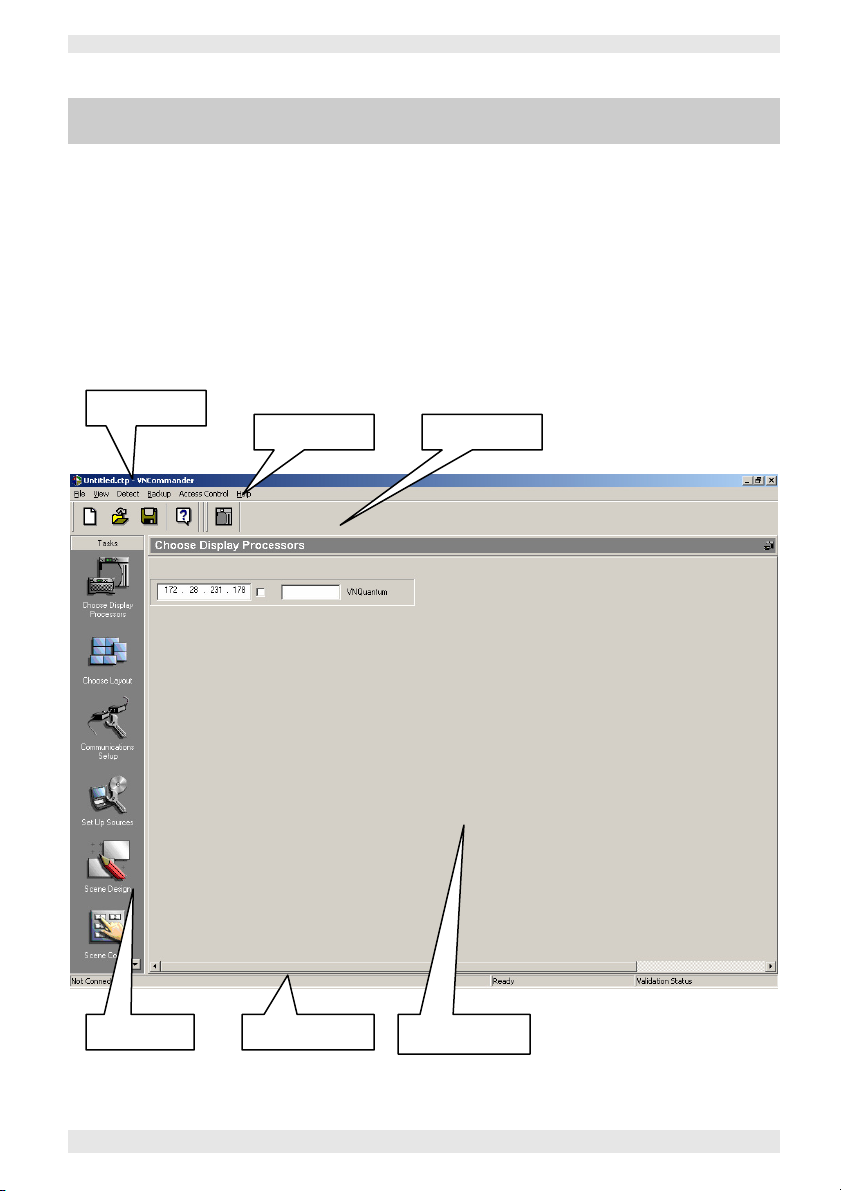
The Main Application Window
The VN-COMMANDER application window comprises
the following elements (see the example in Fig.2):
• Title Bar
• Menu Bar
• Toolbars
• Task Bar
• Workspace
• Status Bar
Title Bar
Menu Bar Toolbars
Fig.2: Elements of the VN-COMMANDER main application window.
I456GB issue 8 15
Task Bar Status Bar Workspace
Page 26

Section 1: Getting Started VN-COMMANDER User Guide
Title Bar
Menu Bar
Task Bar
Shows the name of the currently loaded presentation.
Provides a selection of drop-down menus, giving
access to various functions in VN-COMMANDER. Most
of the menu functions can also be performed by buttons on
the toolbars. The menus available change according to
which task is currently selected on the task bar.
Each major task within VN-COMMANDER is
represented by an icon in the task bar. To select a task,
simply click on the appropriate icon. The workspace,
menus and toolbars associated with the selected task will
then appear.
The full standard set of tasks are as follows (less
tasks may be displayed depending on security
settings):
• Choose Display Processors
• Choose Layout
• Communications Setup
• Set Up Sources
• Scene Design
• Scene Control
Workspace
Each task in the task bar has it’s own workspace. The
workspace contains the controls and functionality
needed to complete the task.
Toolbars
The various toolbars within VN-COMMANDER allow
quick access to the most commonly used functions within
the currently selected task. Most of these functions can
also be performed using the menu bar. To hide or show a
View menu.
Sta tus B ar
toolbar for the current task, use the
Sho w s i n form atio n about t he c urren t st atus of
VN-COMMANDER. To hide or show the status bar, go to
the
View menu and select Status Bar.
16 I456GB issue 6
Page 27

VN-COMMANDER User Guide Section 1: Getting Started
Starting a New Presentation
When you run VN-COMMANDER for the first time after
installation, a new ‘untitled’ presentation will be created with
no system configuration settings.
Thereafter, there are two methods of starting a new ‘untitled’
presentation depending on whether you want to:
• retain the existing system configuration (e.g. to make a new
presentation for the same system), or to
• create a completely new presentation with no system
configuration (e.g. to make a new presentation for a
different system).
To Retain the Existing
System Configuration
To Create a
Completely New
Presentation
~
Click the button on the main toolbar.
You can also choose File | New from the menu bar or press Ctrl +
N on the keyboard.
Exit VN-COMMANDER by following the instructions
on page 14.
While holding down the keyboard SHIFT key, run VN-
COMMANDER by following the instructions on page 14.
Once the VN-COMMANDER application window has appeared,
you can release the SHIFT key.
• To give your ‘untitled’ presentation a name, you need to
save it as described on page 18.
• If you are creating a presentation for a new system or
need to make changes to the existing configuration, refer
to Section 2: System Configuration.
• To start putting sources on the target display, turn to
Section 3: Creating a Presentation
I456GB issue 8 17
Page 28
Section 1: Getting Started VN-COMMANDER User Guide
Loading an Existing Presentation
~
Click the button on the main toolbar.
You can also choose File | Open from the menu bar or
press Ctrl + O on the keyboard.
The standard Windows Open dialog box will appear.
~
Locate the file to be loaded and click the OK button.
Saving a Presentation
Saving the Current
Presentation
Saving a Copy of a
Presentation
~
Click the button on the main toolbar.
You can also choose File | Save from the menu bar or press
Ctrl + S on the keyboard.
If the presentation has not been saved previously (i.e. it
is ‘untitled’), the Save As dialog box will appear, enabling
you to specify a name.
~
From the menu bar, choose File | Save As.
The standard Windows Save As dialog box will appear.
~
Type in an appropriate name for the presentation
in the File Name field. A ‘.CTP’ extension will be
automatically appended to the file name.
~
Click the Save button to save the file.
When you are creating a presentation, remember to save
your work regularly!
For extra protection, you can have VN-COMMANDER
automatically create backup files at regular intervals.
See page 18 for details.
18 I456GB issue 8
Page 29
Browse
VN-COMMANDER User Guide Section 1: Getting Started
Using the Auto-Backup Function
VN-COMMANDER can automatically backup your presentation at
specific intervals.
In the event that any changes are lost before saving
(e.g. due to a power outage), you may be able to limit the amount of work you
have lost by restoring the last auto-backup file.
Setting the
Backup Timer
~
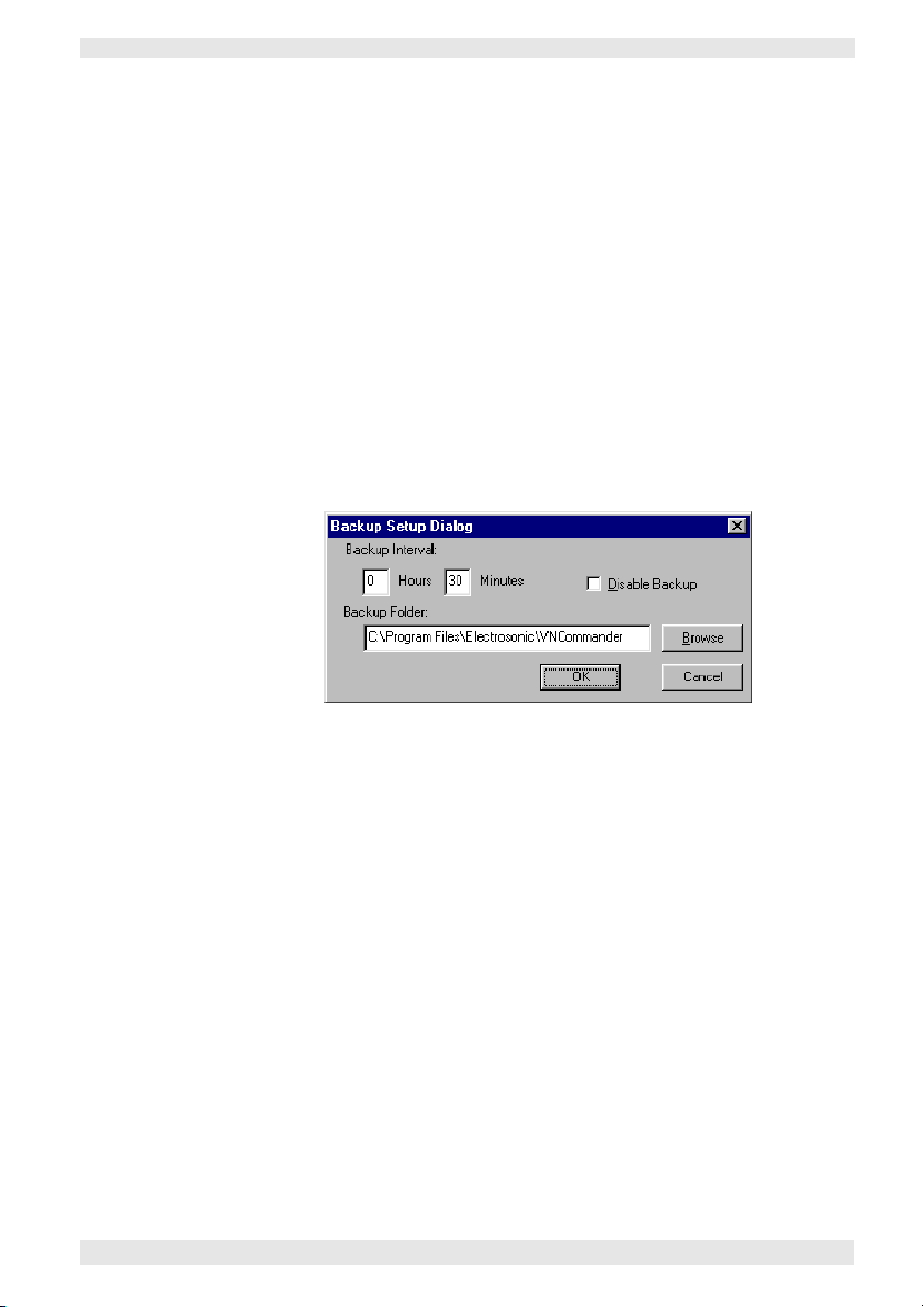
From the menu bar, choose Backup | Setup Backup
Timer.
The Backup Setup dialog box will appear:
~
Ensure that the Disable Backup box is deselected
(unchecked) to enable auto-backup.
If you do not want to use auto-backup, ensure that the
Disable Backup box is selected (checked).
~
Set the desired interval between backups using the
Hours and Minutes fields.
~
Using the Backup Folder area, type in the full path of
the Windows folder where the backup files are to be
saved. By default these will be saved in the VNCOMMANDER folder. Alternatively, click the
button to find a specific folder.
~
Click the OK button to implement the new settings.
I456GB issue 8 19
Page 30

Section 1: Getting Started VN-COMMANDER User Guide
Restoring an
Auto-Backup File
~
From the menu bar, choose Backup | Restore.
~
If you have made changes to the current file you will
be prompted to save the file first. Either:
Click on Yes to save the current
file (in which case the Save As
dialog box will appear).
Click on Save to save the
current file.
The standard Windows Open dialog box will then appear.
NOTE: The backup files are held in folders according to the
date they where created.
~
Double-click the folder for the required date.
Backup files are named with the presentation title and the
time they where created.
~
Double-click the backup file that you want to restore.
Click on No to exit the current
file without saving.
20 I456GB issue 8
Page 31

VN-COMMANDER User Guide Section 1: Getting Started
I456GB issue 8 21
Page 32

Sys tem C o nf i gu r at i on
Introduction
...............................
23
Se c ti o n 2 :
Choosing a Display Processor . 24
Choosing a Display Layout.. . .. 26
•
Target Display Clock........................ 34
Communications Setup ............ 36
Set Up Sources ......................... 42
•
The Set Up Sources Task.................43
•
Source Parameters......................... 50
22 I456GB issue 8
Page 33

VN-COMMANDER User Guide Section 2: System Configuration
Introduction
There are four procedures or ‘tasks’ associated with
configuring VN-COMMANDER to work correctly with a
VN-QUANTUM Processor:
•••• Choosing a Display Processor
Used to establish communications with a
VN-QUANTUM. See page 24 for further details.
•••• Choose a Display Layout
Used to select the format of the target display and
assign screens to a VN-QUANTUM Processor.
See page 26 for further details.
•••• Communications Setup
Used to configure the computer’s serial ports (e.g. to
allow remote control of VN-COMMANDER) and/or
communication with external devices such as source
switchers. This task is also used to enable or disable
XML drivers. See page 38 for further details.
•••• Set Up Sources
Used to define the sources available to the
VN-QUANTUM. See page 43 for further details.
These tasks can be undertaken in any order, although the
order in which they are listed above is recommended.
Unless otherwise stated, all configuration settings described
in this section are saved in the presentation (.ctp) file.
I456GB issue 8 23
Page 34

Section 2: System Configuration VN-COMMANDER User Guide
Choosing a Display Processor
VN-COMMANDER communicates with the
VN-QUANTUM via a direct or indirect Ethernet
connection (as described on page 6).
Before VN- COMMANDER c an take control of a
VN-QUANTUM Processor, it must be detected and
‘connected’ using the Choose Display Processors task.
~
Click on the Choose Display Processors icon in the
task bar:
The Choose Display Processors workspace will appear.
~
Detecting the
Display Processor(s)
Click on the button on the toolbar, or choose the
Detect option from the Detect menu.
V N - C O M M A ND ER w i l l t h e n p o ll f o r a ny
VN-QUANTUM Processors accessible via its Ethernet port.
An information panel is displayed for each Processor
detected, as in the following example:
The IP Address of the detected
Processor. This is for information only
and cannot be changed here.
The type of image processor is
shown here,
e.g.
VNQuantum.
A Connect checkbox, used to enable or
disable communications between this
Processor and VN-COMMANDER.
24 I456GB issue 8
A text box for entering an optional
Name for the Processor.
Page 35

VN-COMMANDER User Guide Section 2: System Configuration
To connect to a VN-QUANTUM Processor...
~
Select (i.e. check) the Connect checkbox for the appropriate processor:
If you are using more than one processor, you need to ‘connect’ to each
processor in this way.
NOTE: If the checkbox does not stay selected, this indicates that VN-
COMMANDER is unable to establish or maintain a connection (e.g. due to a
faulty cable).
To disconnect from a VN-QUANTUM Processor...
~
Deselect (i.e. uncheck) the Connect checkbox for the appropriate processor:
To assign a Name to a VN-QUANTUM Processor...
If you are using VN-COMMANDER to control more than one processor, you
may find it helpful to give a name to each processor that more easily identifies
its role within the system. This will be especially useful when assigning processors
to the target display screens.
For example, if you are using two processors driving the left-hand and righthand sides of the target display respectively, you could name them ‘Left’ and
‘Right.
~
Click on the Name box for the appropriate processor, then type in a suitable
name:
VN-COMMANDER CONNECT does not support the
use of multiple processors.
I456GB issue 8
25
Page 36

Section 2: System Configuration VN-COMMANDER User Guide
Choosing a Display Layout
Your target display may be a single screen, or several
screens butted togther to form a larger display area.
Therefore, you need to define the layout within
VN-COMMANDER.
The chosen layout will also appear as the virtual display
in the Scene Design task (see page 70). This will allow you
to place sources exactly where you want them on the real
display.
The display layout is chosen and configured using the
Choose Layout task.
~
Click on the Choose Layout button on the task bar:
The Choose Layout workspace will appear:
26 I456GB issue 8
Page 37

If the default layouts don’t match your particular display
VN-COMMANDER User Guide Section 2: System Configuration
Choosing &
Configuring a Layout
Mapping Screens to
Processor Outputs
~
From the layout diagrams displayed, click on the
layout that matches the arrangement of your target
display screens.
The currently selected layout is highlighted with a blue
background and red outline.
configuration, see Designing a New Layout on page 28 or
Modifying an Existing Layout on page 30.
~
Right-click on a screen (usually starting with the top
left screen) in the chosen layout.
~
From the popup menu that appears choose Change
Screen Processor IP.
The following dialog will appear:
~
Select the IP address of the Processor you are using
from the Processor IP listbox.
This will list all processors currently ‘connected’ to VNCOMMANDER via the Choose Display Processors task.
If no processors are listed you will need to ‘connect’ to
one as described on page 25.
I456GB issue 8 27
Page 38
Section 2: System Configuration VN-COMMANDER User Guide
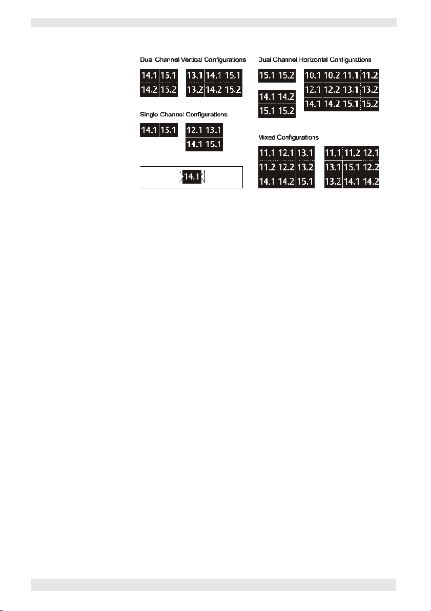
Channel
Number
Card Slot
Number
Fig.3: Example display layouts and channel configurations.
~
Click on Available Outputs to see a list of currently
unassigned output cards (by slot number) and choose
one to assign to this screen.
IMPORTANT NOTE: There are two output channels on each
Output Card and choosing from the Available Outputs list
assigns the primary output (channel 1) to the screen. The
secondary output (channel 2) is assigned automatically
using the Second Output setting. (See Fig.3 for examples.)
~
In the Second Output area, select how you want the
secondary output to be assigned. Choose from:
•••• Horizontal – the secondary output is assigned to
the screen immediately to the right of the primary
output (when viewed from the front of the display).
•••• Vertical – the secondary output is assigned to the
screen immediately below the primary output.
•••• Don’t Assign – the secondary output is not
assigned; the primary output only is used.
~
Click OK to confirm the assignments.
NOTE: Screens that have been assigned/mapped will appear
with a gre en backg round in the lay out diag ram.
Unassigned screens have a grey background.
28 I456GB issue 8
Page 39

VN-COMMANDER User Guide Section 2: System Configuration
Designing a
New Layout
If the target display layout that you require is not one of
the default options available, you can create your own
rectangular layouts as follows:
~
From the menu bar, choose Layouts | New. The
New Wall Layout dialog will appear.
~ Enter a name or brief description for the layout in the
Name box.
~ In the Wall Layout area set the overall horizontal and
vertical size of the target display (measured in whole
screens) using the Columns and Rows settings
respectively.
~ Define the resolution of each screen using the Output
Mode parameter.
IMPORTANT NOTE: This sets up the correct screen
mapping used to determine grid snaps and source
window scaling.
I456GB issue 8 29
Page 40

Section 2: System Configuration VN-COMMANDER User Guide
~
If the display devices are overscanned, you can set the
amount of compensation required by using the Overscan
controls.
~
If you are using projectors with soft edge blending, you
can set the amount of overlap required by using the Screen
Overlap controls.
~
When you have completed setting-up the new layout, click on
the OK button to save it.
~
The new layout can now be selected using the Choose Layout
task (see page 26). You will then need to map screens to
processor outputs (see page 27).
VN-COMMANDER CONNECT does not support the
use of overscan or overlapped displays.
30 I456GB issue 8
Page 41

VN-COMMANDER User Guide Section 2: System Configuration
Modifying an
Existing Layout
~
Right-click on a screen in the chosen layout, then
choose Edit Wall Layout from the pop-up menu.
The Wall Layout Properties dialog box will appear:
~
Edit the various settings as required then click on the
OK button.
Refer to Designing a New Layout on page 29 for further
details on these settings.
I456GB issue 8 31
Page 42

Section 2: System Configuration VN-COMMANDER User Guide
Importing a Layout You can import display layouts from another
VN-COMMANDER file (with a ‘.ctp’ file extension).
~
From the menu bar, choose Layout | Import.
The Import Wall Layout dialog will appear.
~
Locate the file that contains the desired layout and
click the OK button.
NOTE: This action will import all layouts from the selected file
that don’t already exist in the existing file. Any unwanted
layouts can be deleted as described below.
Deleting a Layout You can delete any of the display layouts that appear in
the Choose Layout workspace. Please note that you
cannot undo this operation.
~
Click on the layout to be deleted.
~
From the menu bar, choose Layout | Delete.
32 I456GB issue 8
Page 43

VN-COMMANDER User Guide Section 2: System Configuration
Arranging Layouts You can change the way that layouts are presented in the
Choose Layout workspace. This can be helpful if you
have a large number of layouts and want to be able to see
them more easily.
~
From the menu bar, choose View | Arrange Layouts.
The Arrange Layouts dialog will appear.
~
Select the relative Panel Size for the display layout
and how many Columns of icons you want displayed
across the workspace.
~
Click the OK button.
Restoring Default
Layouts
You can restore the default layouts that were present
when VN-COMMANDER was first installed. Performing
this operation will delete any user-defined layouts.
~
From the menu bar, choose Layout | Default.
I456GB issue 8 33
Page 44

Section 2: System Configuration VN-COMMANDER User Guide
Target Display Clock
The VN-QUANTUM Processor has the ability to show
the current time and date on one or more screens of the
target display.
NOTE: This feature is provided for legacy support
ONLY. The target display clock should not be used for
new systems. Please see the section on the ‘Timer source’
for details of the recommended alternative. (Page 62).
The time and date text will always display in front of any
sources applied to the screen.
~
In the Choose Layout workspace, right-click on the
appropriate screen of the current display layout.
~
From the popup menu that appears choose
Clock Properties.
The following dialog box will appear:
34 I456GB issue 8
Page 45
VN-COMMANDER User Guide Section 2: System Configuration
~
Select the Show Clock checkbox to display the clock or
deselect it to hide the clock.
~
Change the Time and/or Date formats as required.
~
Change the Style settings as required.
Note that when Transparent is selected, the text is
displayed without a background.
~
Choose the position of the clock on the screen by
clicking one of the buttons in the Location area.
~
Click Apply or OK to save the clock settings.
VN-COMMANDER CONNECT does not support the
use of the target display clock.
The target display clock should not be used for
new systems. The target display clock and clock
windows should not be used in the same VNCOMMANDER show as unpredictable results will
occur.
A timer source type also exists (see page 62) which
allows you to create a clock display within a
window. This can then be positioned anywhere on
the display and be changed from scene to scene.
I456GB issue 8 35
Page 46

Section 2: System Configuration VN-COMMANDER User Guide
Communications Setup
You will need to ensure that the computer’s serial ports
are correctly configured if:
• you are using VN-COMMANDER to control external
devices such as source switchers, and/or
• you wish to remotely control VN-COMMANDER
using serial data strings.
The serial ports are setup using the Communications
Setup task, as shown below:
~
Click on the Communications Setup button on the
task bar:
The Communications Setup workspace will appear:
36 I456GB issue 8
Page 47

VN-COMMANDER User Guide Section 2: System Configuration
The left-hand side of the Communications Setup
workspace contains a ‘Devices tree’, similar to Windows
Explorer. This has three main ‘folders’:
•••• Ethernet Devices, which lists any Ethernet device
drivers currently loaded.
•••• Serial Devices, which lists any serial device drivers
currently loaded. Alternatively, if no device drivers
are found, any available serial (COM) ports detected
by VN-COMMANDER will be listed.
•••• Settings, which allows XML device drivers to be
enabled or disabled for serial or Ethernet control (see
page 38).
The details displayed in the main area of the workspace
changes according to the type of item selected in the
device tree.
I456GB issue 8 37
Page 48

Section 2: System Configuration VN-COMMANDER User Guide
XML Device Drivers
Device drivers are defined by an XML file, located in
the following folder on the computer’s hard disk:
“C:\Program Files\Electrosonic\VNCommander\XML\Device Drivers”
For further advice on creating an XML device driver file,
please contact Electrosonic Product Support.
To enable XML Device Drivers...
~
Open the Settings folder and click the XML
Driver Path item.
~
An Enable XML device drivers checkbox will
appear on the right-hand side of the screen. Check
this box to load the device drivers.
A message box will appear while VN-COMMANDER
loads the drivers after which the driver names will
appear in the Ethernet Devices and/or Serial Devices
folders.
38 I456GB issue 8
Page 49

VN-COMMANDER User Guide Section 2: System Configuration
To manually setup a Serial (COM) Port...
Any unused serial ports (i.e. not used by a device driver)
will be listed in the Serial Devices folder. These can be
configured manually as follows:
~
Click on the appropriate port number (e.g. COM1,
COM2, etc.) in the Serial Devices folder.
The Port Settings and Serial Commands areas will appear
in the workspace.
~
In the Port Settings area, adjust the various
parameters as required:
* All settings must match the data format expected by (or
received from) the external switchers/devices.
Sets the Baud rate* of the data
Sets the number of Data bits*
Sets the Parity of the data
Sets the number of Stop bits
Sets the Flow control
I456GB issue 8 39
Page 50

Section 2: System Configuration VN-COMMANDER User Guide
~
In the Serial Commands area, select whether the port
is to be used for incoming (INPUT) or outgoing
(OUTPUT) data, by selecting the appropriate
checkbox:
NOTE: Only one port can be used for input and only one for
output. The Current Ports area shows which ports are
currently in use. You can, if required, use the same port for
both input and output.
40 I456GB issue 8
Page 51

VN-COMMANDER User Guide Section 2: System Configuration
Testing an
Ethernet Device
~
Click on an installed Ethernet device to display a
workspace like the following example:
~
Click the Connect button to establish a connection
with the device. Status box will show ‘Connected’ if
successful.
~
Click on a command in the Command list and click
Send to transmit that command to the device.
If a command requires a specific argument (e.g. a Search
frame number) this can be typed into the Argument box
before pressing Send).
I456GB issue 8 41
Page 52

Section 2: System Configuration VN-COMMANDER User Guide
Testing a
Serial Device
~
Click on an installed Serial device to display a
workspace like the following example:
~
Check that the Status box shows ‘Connected’. If not
click the Connect button to establish a connection
with the device.
~
Click on a command in the Command list and click
Send to transmit that command to the device.
If a command requires a specific argument (e.g. a Search
frame number) this can be typed into the Argument box
before pressing Send).
42 I456GB issue 8
Page 53

VN-COMMANDER User Guide Section 2: System Configuration
Set Up Sources
Each source that you need to use in your presentation
must have a corresponding ‘source definition’ within
VN-COMMANDER.
What is a Source A source definition contains full details of the source,
Definition? such as its signal format (e.g. NTSC, PAL, RGB, DVI etc.)
and which input channel on the VN-QUANTUM
Processor the source is connected to.
If you are using an external source switcher (e.g. to give
access to multiple sources on one input) the source
definition can also include a serial command string used
to operate the switcher. A separate source definition is
required for each of the sources that can be connected to
the VN-QUANTUM Processor.
Remember that you will need to setup communications
with a switcher before you can define any sources
selected via that switcher. See page 35 for further details.
When VN-COMMANDER needs to display a particular
source, it uses the parameters in the source definition to
configure the appropriate input channel for the required
source.
Source definitions are created and set up using the Set Up
Source task (see page 43).
VN-COMMANDER CONNECT does not support the
use of Glimpse, Clock, HTML and picture source types.
I456GB issue 8 43
Page 54

Section 2: System Configuration VN-COMMANDER User Guide
Source explorer
Source p
roperties
area
The Set Up Sources Task
~
Click on the Set Up Sources button on the task bar:
The Set Up Sources workspace will appear as shown below.
Fig.4: The Set Up Source Workspace.
44 I456GB issue 8
When you open the source explorer after creating a
completely new presentation (or for the first time after
installation) there will be no source definitions listed.
To start adding and configuring source definitions, see
page 46 onwards.
Page 55

VN-COMMANDER User Guide Section 2: System Configuration
Source Explorer The source explorer, located on the left-hand side of the
Set Up Source workspace, shows a list of Source Types
supported by the VN Processor. Source Definitions are
listed under the relevant Source Type.
The source explorer operates in a similar fashion to the
Windows Explorer; the information is displayed as a
‘tree’ which expands up to three ‘levels’ as shown in the
following example:
Fig.5: The source explorer.
When you open the source explorer after creating a
All Display Processors
VN-QUANTUM Processor
Source Type
Source Definition
completely new presentation (or for the first time after
installation) there will be no source definitions listed.
To start adding and configuring source definitions, see
page 47 onwards.
I456GB issue,8
45
Page 56

Section 2: System Configuration VN-COMMANDER User Guide
To create VN-QUANTUM Source Types...
~
Right-click on the Display Processors item.
~
A number of options are presented.
- Create Quantum Sources:
This option will simply add a list of the supported source
types to the source tree. You will then need to create source
definitions as described in the next few pages.
- Detect sources:
Selecting this option is the easiest method to create source
types. For correct operation, you should have a VNQUANTUM processor connected to the VN-COMMANDER
control PC. VN-Commander communicates with the
Quantum processor and automatically detects the number
and type of input cards that are present. The source type list
will be built automatically. If sources are connected to the
processor, then the source definition will be created
automatically.
- Update sources:
Selecting this option when connected to a VN-QUANTUM
processor will cause the source tree details to be updated.
46 I456GB issue 8
Page 57

VN-COMMANDER User Guide Section 2: System Configuration
To create a Source Definition...
~
Right-click on the appropriate source type heading in
the source explorer (e.g. RGB, Glimpse, Video, etc.)
~
Select Create New Source from the popup menu.
An empty source definition will appear in the workspace. For example, a new
Video definition will look like this:
~
Enter a name for the source in the Source Name field.
~
If a serial string is required for this source (e.g. to operate an external
switcher), type the appropriate control string into the Source Selected TX
field.
~
Enter the required settings for the source in the Parameters area – these
settings vary according to the source type and are detailed on pages 50 thru
66.
I456GB issue 8 47
Page 58

Section 2: System Configuration VN-COMMANDER User Guide
If VN-COMMANDER is connected to a VN-QUANTUM
Processor you can click the Detect Sources button to
display a list of the Video, RGB, DVI etc sources that are
currently connected.
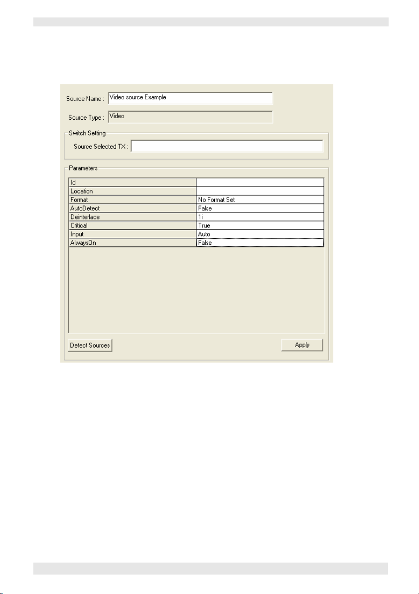
The following example shows what you might see if you
use Detect Sources within a Video source definition:
Simply click on a source from the list and click OK to
create a source definition for the chosen source.
48 I456GB issue 8
Page 59

VN-COMMANDER User Guide Section 2: System Configuration
To delete a single Source Definition...
~
Right-click on the appropriate source definition in the
source explorer.
~
Select Delete Source from the popup menu.
To delete ALL Source Definitions...
~
Right-click on the Display Processors item.
~
Choose Remove All Devices from the popup menu.
I456GB issue 8 49
Page 60

Section 2: System Configuration
VN-
COMMANDER User Guide
Source Parameters
The following pages show the source parameters for each
VN-QUANTUM source type, along with a description of
functionality and available options.
50 I456GB issue 8
Page 61

VN-COMMANDER User Guide Section 2: System Configuration
Source Parameters - DVI
Use the DVI source type to view a source connected to an ES3314 DVI
Input Card.
I456GB issue 8 51
Page 62

Section 2: System Configuration VN-COMMANDER User Guide
Id
Location
Format
The source input number on VN-QUANTUM
identified by the card slot number and card
input number,
input 2 of the card in slot 5.
This value can be entered manually or detected by
using the Detect Sources button (see Helpful Hint
on page 48).
The IP address of the VN-QUANTUM card frame
where the source is connected.
This value can be entered manually or detected by
using the Detect Sources button (see Helpful Hint
on page 48).
A read-only field that reports the source type as
detected by VN-QUANTUM.
RGB – default mode.
Component SD – option for Component SD i/p’s Colour space
Component HD – option for Component HD i/p’s
e.g.
5.2 is the source connected to
52 I456GB issue 8
Page 63

VN-COMMANDER User Guide Section 2: System Configuration
Source Parameters - GLIMPSE
Use the Glimpse source type to display a source derived from a VNGLIMPSE Server or VN-GLIMPSE RGB Adapter.
I456GB issue 8 53
Page 64
Section 2: System Configuration VN-COMMANDER User Guide
Server
IPAddress
Multicast
Address
MulticastPort Default = 5000
Input Enabled NOT IMPLEMENTED.
Input Stop
Keystroke
Input Timeout
(Seconds)
Reconnection
Time (Seconds)
Specifies the network Name* or IP Address of
the VN-GLIMPSE source.
*For VN-GLIMPSE Server, this is the name of the
host/source computer. For VN-GLIMPSE RGB
Adapter, this is the name of the RGB Adapter itself.
To use names the network must support DNS
(Dynamic Name Services).
For example, to select a VN-GLIMPSE Server
source on a PC called GlimpsePC with an IP
address of 172.28.229.101, enter either:
GlimpsePC or 172.28.229.101
The IP address of the VN-GLIMPSE RGB
Adapter where the source is connected.
Must be left blank if the Adapter is using DHCP.
If the source is a VN-GLIMPSE RGB Adapter
operating in Multicast mode, enter its Multicast
address here. For example: 234.5.6.183
NOT IMPLEMENTED.
NOT IMPLEMENTED.
NOT IMPLEMENTED.
54 I456GB issue 8
Page 65
VN-COMMANDER User Guide Section 2: System Configuration
Source Parameters - GLIMPSE
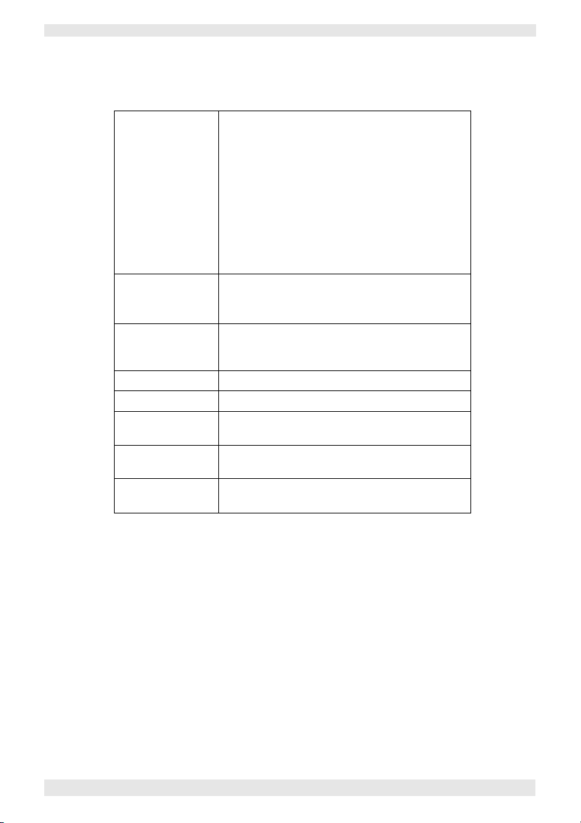
Use the HTML source type to display a browsercompatible file format.
I456GB issue 8 55
Page 66

Section 2: System Configuration VN-COMMANDER User Guide
URL
Graphics Overlay
The URL of a web resource or path and filename
t o a l ocal / n e t w or k- ba s e d H T ML file.
For example, www.electrosonic.com
NOT IMPLEMENTED.
Default = False.
VN-COMMANDER CONNECT does not support the
use of Glimpse sources.
56 I456GB issue 8
Page 67

VN-COMMANDER User Guide Section 2: System Configuration
Source Parameters - Picture
Use the Picture source type to display an image file (in JPG, GIF,
PNG or BMP format). The file can be located on the VN-QUANTUM
flash drive (in the d:/pictures folder) or elsewhere on the network.
I456GB issue 8 57
Page 68

Section 2: System Configuration
VN-
COMMANDER User Guide
transparent (if Graphics Overlay is set to Tru
e).
Three values from 0 to 255 are used to set the
Red, Green and Blue levels.
Filename
Location
GraphicsOverlay
KeyColour
The filename of the required image, including
its path.
For example, to select a file on the VNQUANTUM Processor, use the format:
d:/pictures/companylogo.jpg
Alternatively, to select a file on a network
computer/server, use the format:
\ \ imageserver\ companylogo.jpg
The IP address of the VN-QUANTUM card
frame where the source is connected.
This value can be entered manually or detected
by using the Detect Sources button (see Helpful
Hint on page 48).
Set to True to make the specified KeyColour in
the image become transparent.
Set to False to disable transparency (KeyColour
will be opaque).
Sets the colour in the image that will be made
VN-COMMANDER CONNECT does not support the
use of Picture sources.
58 I456GB issue 8
For example:
255,255,255 = White
0,0,0 = Black
0,0,255 = Blue
Page 69

VN-COMMANDER User Guide Section 2: System Configuration
Source Parameters – RGB
Use the RGB source type to view an RGB graphics or HD video source
connected to an ES3312 RGB Input Card.
I456GB issue 8 59
Page 70

Section 2: System Configuration VN-COMMANDER User Guide
Item
Source Name Enter the name for the source.
Switch
setting
Source
Format
Adjustments
Source
Viewporting
Note1: For a more detailed description of these controls, please contact
Electrosonic for an application note.
Control Action
Source ID The slot and channel number of the RGB card
in the Quantum frame is listed.
Source Location The IP address of the Quantum frame is listed
Format Only accessible when in ‘manual’ mode.
Lists the standard modes that are available.
Colour space Select the required colour space
Auto detect The format of the source that is connected to
the card is detected automatically.
Manual When this mode is enabled, the input mode
may be forced to a known format.
In addition new ‘custom’ input modes may be
built. Note 1
Brightness, Contrast Used to adjust the brightness and contrast of a
source.
Phase, Pixel clock Used to adjust the sample clock parameters.
Note: ensure that ‘auto phase’ is not checked.
Auto phase Checked: Automatically adjusts the clock
phase.
Un-checked: No auto clock phase adjust.
X, Y, H pos, V Pos These controls allow a section of the captured
source to be isolated as a viewport. Note: only
one viewport for each input channel.
Image Auto centre Off: no auto centering
Once: the source image is centered as part of
the detect process.
Continuous: the input source is continually
monitored and centered.
Checked The source is displayed in the current scene Keep scene
Un-checked The source is displayed on Quantum output
1,1.
60 I456GB issue 8
Page 71
VN-COMMANDER User Guide Section 2: System Configuration
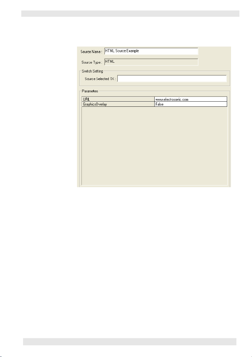
Source Parameters – Video
Use the Video source type to view a video source connected to an
ES3311 Video Input Card.
I456GB issue 8 61
Page 72

Section 2: System Configuration VN-COMMANDER User Guide
Auto: Auto discover format
Id
Location
Format
AutoDetect
Deinterlace
Critical*
Input
Always on
The source input number on VN-QUANTUM
identified by the card slot number and card
input number,
input 3 of the card in slot 5.
This value can be entered manually or detected
by using the Detect Sources button (see Helpful
Hint on page 48).
The IP address of the VN-QUANTUM card
frame where the source is connected.
This value can be entered manually or detected
by using the Detect Sources button (see Helpful
Hint on page 48).
When AutoDetect is set to True this is a
read-only field that reports the source type as
detected by VN-QUANTUM.When AutoDetect
is set to False this is a drop-down list allowing
the manual selection of a source type.
Set to True to allow VN-QUANTUM to
auto-detect the current source type.
Set to False to manually select the source type
using the Format drop down list.
Sets the de-interlace mode to be applied to the
source. Choose between:
1i – Single Field Interpolation
3i – Three Field Interpolation
Refer to the VN-QUANTUM User Guide for
further advice on de-interlacing.
When set to True the VN-QUANTUM will treat
this as a critical source (guaranteed to display
in real-time).
When set to False the VN-QUANTUM will
treat this as a non-critical source (fields may get
dropped if RAPT bandwidth is exceeded).
SVideo: Force S-Videomode
Composite: Force Composite mode
False:
True:
e.g.
5.3 is the source connected to
62 I456GB issue 8
* Initial firmware releases for VN-QUANTUM only support
the use of Critical sources.
Page 73

Timer
VN-COMMANDER User Guide Section 2: System Configuration
Use the Timer source type to create an on-screen clock or
count-down/up timer.
IMPORTANT NOTE: Do not mix Timer/Clock source windows
with the Target Display Clock function (see page 34) as
unpredictable results may occur. Use one method or the other
to show a clock on the target display
I456GB issue 8 63
Page 74

Section 2: System Configuration VN-COMMANDER User Guide
Id
GraphicsOverlay
Size
ForeColour
BackColour
Font
TimeFormatString
A user-defined alphanumeric label (
source name) that is unique to the show.
Set to True to make the specified BackColour in
the image become transparent.
Set to False to disable transparency
(BackColour will be opaque).
Choose the text size of the clock/timer display
from:
Small
Medium (default)
Large
Extra Large
Sets the foreground (
clock/timer display. Three values from 0 to 255
are used to set the Red, Green and Blue levels.
For example:
255,255,255 = White (default)
128,0,0 = Mid Red
255,255,0 = Bright Yellow
Sets the background colour for the clock/timer
display. Three values from 0 to 255 are used to
set the Red, Green and Blue levels.
For example:
0,0,0 = Black (default)
128,0,0 = Mid Red
0,0,75 = Dark Blue
Sets the font used for the clock/timer display.
The options are dependant on the fonts
installed on the VN-QUANTUM processor.
Typically the options will comprise:
Arial
Verdana (default)
Microsoft Sans Serif
Tahoma
Use to customize the time/date text string.
Use %d to display the date, %t to display the
time, and /n to force a new line.
If left blank the time/date are displayed in
standard form.
i.e.
text) colour for the
e.g.
the
64 I456GB issue 8
Page 75

VN-COMMANDER User Guide Section 2: System Configuration
TimeFormat
ShowSeconds
ShowDate
DateFormat
ShowWeekDay
TimerStartTime
ClockMode
TimeZone
Alignment
Select either 12 hour time format or 24 hour.
Default is 24.
When set to True the time display will include
hours, minutes and seconds.
When set to False the time display will show
hours and minutes only.
When set to True the date is displayed along
with the time.
When set to False only the time is displayed.
Set the format of the date displayed from the
following options:
dd/mm/yyyy (default)
mm/dd/yyyy
20 June 2006
June 202006
When set to True the day of the week is
displayed (Monday to Saturday) with the date.
When set to False only the date is displayed.
When operating in Timer mode, this value
defines the start time in hh:mm:ss.
Default is 00:00:00.
Note: When zero is reached in count down mode,
the timer reloads with this preset value and starts
again.
Choose whether the display will show a
standard Clock (default) or a Timer.
Note: For timer mode, set the TimerCountDirection
parameter as required (see below).
Sets the time zone (from the drop down list) for
the clock and date.
Sets the horizontal alignment of the display,
relative to the window in which it is placed.
Left
Center (default)
Right
I456GB issue 8 65
Page 76

Section 2: System Configuration VN-COMMANDER User Guide
Up
(default)
Product Support.
Trimming
TimerCount When using Timer mode, use this parameter to
Direction set the direction that the timer will count from:
Sets how the date/time text string is treated
when the window is smaller that the text.
None: no trimming - the text is truncated.
Character (default): the string is broken at the
boundary of the last character that is inside the
layout rectangle.
Word: the string is broken at the boundary of
the last word that is inside the window.
Ellipsis Character: the string is broken at the
boundary of the last character that is inside the
window and an ellipsis (...) is inserted after the
character.
Ellipsis Word: the string is broken at the
boundary of the last word that is inside the
window and an ellipsis (...) is inserted after the
word.
Ellipsis Path: the center is removed from the
string and replaced by an ellipsis. This keeps as
much of the last portion of the string as possible
Cmd
Note: A left-click on the timer window in the Scene
Down
A command to control timer operation. Thee
commands are supported: Start, Stop and
Reset.
For more details on how to change these
commands on-the-fly, contact Electrosonic
Design task simulates a Start/Stop command; a
right-click simulates a Reset command.
VN-COMMANDER CONNECT does not support the
use of Clock or Timer sources.
66 I456GB issue 8
Page 77

VN-COMMANDER User Guide Section 2: System Configuration
I456GB issue 8 67
Page 78

Introduction
................................
...........
69
Secti on 3:
Cr e a t i n g a P r e s en ta t i o n
68 I456GB issue 8
Working with Scenes ...........................71
•
Creating a New Scene.................................. 71
•
Changing the Properties of a Scene ....... 73
•
Adding or Changing Scene Commands. . 74
•
Copying an Existing Scene............................. 77
•
Changing the Order of Scenes........................ 77
•
Scene Navigation......................................... 78
•
Deleting a Scene......................................... 78
Working with Windows .........................79
•
Adding a Window to a Scene.......................... 81
•
Removing a Window from a Scene......................81
•
Choosing the Window Source......................... 82
•
Choosing the Window Style............................ 83
•
Changing a Source Viewport.......................... 87
•
Moving and Resizing a Window ...................... 90
•
Changing the Layer of a Window..................... 93
•
Changing the Virtual Display Properties....................95
Page 79

VN-COMMANDER User Guide Section 3: Creating a Presentation
Introduction
Windows & Scenes To view a source on the target display you need to place a
‘window’ (containing the appropriate source) on the
display.
The size, position and contents of one or more windows
can be stored as a ‘scene’. You can create any number of
scenes, each having a different arrangement of windows
and/or sources.
NOTE: The maximum number of windows allowed within a
scene is dependant the VN-QUANTUM hardware. Broadly the
absolute maximum is 64 windows arranged as an 8x8 array on
a single output channel. Check the VN-QUANTUM User
Guide forfurther details.
Scene Designer Windows and Scenes are created and edited using the
Scene Designer.
~
To access the Scene Designer, click on the Scene
Design icon in the task bar:
The Scene Design workspace will appear.
The main features and toolbars associated with the Scene
Design workspace are shown in Fig.6.
I456GB issue 8 69
Page 80

Section 3: Creating a Presentation
VN-
COMMANDER User Guide
Virtual Display Properties Toolbar
Window Palette
Scene Control Toolbar
Virtual Display Area
Scene List
Window Properties Toolbar
Scene Properties Toolbar
Fig.6: Main features and toolbars of the Scene Designer.
70 I456GB issue 8
Page 81

VN-COMMANDER User Guide Section 3: Creating a Presentation
Working with Scenes
Creating a New Scene
The ‘new’ scene is added to the end of the Scene List.
The new scene will have the same window palette
(see page 78) as the ‘currently selected’ scene. No other
attributes are copied from the current scene.
~
Click the button on the Scene Properties toolbar.
The Scene Properties dialog will appear:
Use these three’ tabs to
enter control commands
that will be sent as part
of the scene selection.
S eepage s73 –75fo r
further details.
These options relate to
the AutoPlay facility;
see pages 113–116.
Check this box to send
Scene Commands only
w hen th is sce ne i s
selected.
See Hint on page 71.
I456GB issue 8 71
Page 82

Section 3: Creating a Presentation VN-COMMANDER User Guide
~
Modify the default Scene Title and any other settings
as required.
~
Click the OK button.
In the Scene Controller, a new recall button will also be
added for the ‘new’ scene (see page 100).
~
To add a window to the scene, see page 81.
By checking the Don’t display windows box in the
Scene Properties dialog, only the serial strings (if any)
associated with the string will be actioned. Any source or
layout changes in the scene will be ignored. This allows
the scene to be used simply to transmit a serial command
without changing the current layout of the target display,
e.g. to operate an external source switcher.
72 I456GB issue 8
Page 83

VN-COMMANDER User Guide Section 3: Creating a Presentation
Changing the Properties of a Scene
~
For the currently selected scene, click on the
button on the Scene Properties toolbar, or for any
scene right-click on the scene title in the Scene List.
The Scene Properties dialog will appear:
~
Modify the details as required, then click on the OK
button.
NOTE: Any changes made to the Scene Title will not automatically
update the Button Text displayed on the corresponding scene recall
button, located in the Scene Controller (see page 108).
I456GB issue 8 73
Page 84

Section 3: Creating a Presentation VN-COMMANDER User Guide
Adding or Changing Scene Commands
~
For the currently selected scene, click on the
button on the Scene Properties toolbar, or for any
scene right-click on the scene title in the Scene List.
The Scene Properties dialog will appear.
~
Click on the appropriate Scene Commands tab:
•••• Pre (as soon as the scene is selected but not yet
fully displayed);
•••• Post (when the scene display is fully complete);
•••• Exit (when another scene is selected but before the
Pre commands of the new scene).
NOTE: The method of adding, editing or removing commands
from each tab is the same.
74 I456GB issue 8
Page 85

VN-COMMANDER User Guide Section 3: Creating a Presentation
To add a scene command...
~
Open the Scene Properties dialog (if not already) and
select the appropriate Scene Commands tab.
~
Click the Add button to display the Add Command
dialog:
~
Using the Device listbox select the device you want to
add a command for.
~
Click on the required Command Name from the list.
If you select a non-XML defined serial port (which will be
listed as OUTPUT), a text box will be displayed for you to
enter afree format text string.
~
Click the OK button to add the command to the
scene.
I456GB issue 8 75
Page 86

Section 3: Creating a Presentation VN-COMMANDER User Guide
To change the order of scene commands...
~
Open the Scene Properties dialog (if not already) and
select the appropriate Scene Commands tab.
~
In the command list click on the Device name to be
moved.
~
Click the Move Up or Move Down buttons to move
the command to the required position in the list.
To remove a scene command...
~
Open the Scene Properties dialog (if not already) and
select the appropriate Scene Commands tab.
~
Click on the Device name in the command list
and click the Remove button.
To edit a serial (OUTPUT) scene command...
~
Open the Scene Properties dialog (if not already) and
select the appropriate Scene Commands tab.
~
Click on the OUTPUT name in the command list and
click the Edit button.
~
Edit the free format text string as required then click
the OK button.
76 I456GB issue 8
Page 87

VN-COMMANDER User Guide Section 3: Creating a Presentation
Copying an Existing Scene
You can create an exact copy of any scene that already
exists in your presentation. This is useful, for example,
when creating a number of scenes which only have slight
variations from each other.
The ‘copied’ scene is inserted immediately after the
‘original’ scene. The copied scene will have the same
window palette, window layout, control commands and
auto-play settings as the original scene.
~
Select the scene to be copied by clicking on its name
in the Scene List.
~
Click the button on the Scene Properties toolbar.
The Scene Properties dialog will appear for the ‘copied’
scene. See example dialog on page 70.
~
Modify the default Scene Title and any other settings
as required.
~
Click the OK button.
In the Scene Controller, a new recall button will also be
added for the ‘copied’ scene (see page 100).
Changing the Order of Scenes
You can change the order of the scenes in the Scene List.
When using the AutoPlay facility, scenes are recalled in
the order that they appear in this list.
~
To move a scene in the Scene List, simply drag and
drop the scene title to a new position in the list.
I456GB issue 8 77
Page 88

Section 3: Creating a Presentation VN-COMMANDER User Guide
Scene Navigation
You can use the Scene Control toolbar, Scene List and
keyboard to navigate to the scene you want to view or
edit.
Deleting a Scene
To go to...
a Specific Scene
the Next Scene
the Previous Scene
the First Scene
the Last Scene
~
Ensure that the scene to be deleted is currently
displayed (e.g. by clicking on the appropriate scene
title in the Scene List).
Click on the..
scene title in the Scene List.
the button, or
press the down arrow key.
the button, or
press the up arrow key.
the button, or
press the Home key.
the button, or
press the End key.
~
Click the button on the Scene Properties toolbar.
In the Scene Controller, the corresponding scene recall
button will also be deleted (see page 100).
78 I456GB issue 8
Page 89

VN-COMMANDER User Guide Section 3: Creating a Presentation
Working with Windows
Virtual Display Area Within the Scene Designer the real target display is
represented by the virtual display area, and each window
that can be placed on the real display is represented by a
virtual window.
Each virtual window has a unique number (automatically
assigned by VN-COMMANDER) and a user-definable
label, typically used to identify the source:
Window Number – a number that uniquely
identifies each window within a scene.
This window contains a
source called Video Server.
The Window Palette When you create a new presentation, nine virtual
windows are ‘docked’ in the window palette. You can
add more windows if required (see page 79) but, once
added, they cannot be deleted.
The contents of each window can be the same or different
between scenes. Initially, each window will contain a
gray color wash. Later on, as you create new scenes, the
content of each window in the palette is copied from the
currently selected scene.
To use a window within a scene it is moved (or
‘undocked’) from the window palette into the virtual
display area.
I456GB issue 8 79
This window contains a
source called Workstation.
Page 90

Section 3: Creating a Presentation VN-COMMANDER User Guide
The appearance of the window in the palette changes
depending on whether it is docked (not used in the scene)
or undocked (is used in the scene):
Example of a Docked Window...
To add more Windows to the Palette...
Remember that windows cannot be deleted from the
windows palette.
~
Either:
• Right-click anywhere in the window palette, or
• Right-click in the virtual display or workspace
area (but not on an existing window).
~
From the pop-up menu that appears, choose the
Add Window option.
A new window will appear containing a default color wash
and given the next available window number.
Exampl e of a n U ndocke d
Window (note the smaller image
and gray border)...
When you place the mouse pointer over any window in
the palette a pop-up box will appear showing the
window number and its source type.
For example:
80 I456GB issue 8
Page 91

VN-COMMANDER User Guide Section 3: Creating a Presentation
Adding a Window to a Scene
~
Click on an available window in the window palette.
It will be highlighted with a red outline.
~
Then, either:
• Click on the button on the Window
Properties toolbar, or
• Drag the window into the virtual display area, or
• Press the Delete key on the keyboard.
~
To choose a source to go in the window, see page 82.
Removing a Window from a Scene
~
Click on the appropriate window either in the
window palette or in the virtual display area.
~
The either:
• Click on the button on the Window
Properties toolbar, or
• Drag the window into the window palette, or
• Press the Delete key on the keyboard.
I456GB issue 8 81
Page 92

Section 3: Creating a Presentation VN-COMMANDER User Guide
Choosing the Window Source
~
Open the Set Window Properties dialog by either:
• Right-clicking on the window in the palette or virtual
display and choosing Window Properties from the
pop-up menu, or
• Choosing the Windows | Window Properties
from the menu bar, or
• Pressing the key on the computer keyboard,
with the appropriate window already selected.
~
Click the VNQuantum Sources tab, then click on the
required source using the source tree:
NOTE: The parameters displayed are for reference only. To
change source parameters, see Set Up Sources on page 43.
82 I456GB issue 8
Page 93

VN-COMMANDER User Guide Section 3: Creating a Presentation
Choosing the Window Style
VN-COMMANDER CONNECT does not support the
use of Window styles
Each window can be given a text label (to identify the source on the target
display) and, if required, a colored border.
Two types of text label can be applied to a window:
•••• Overlay Text, where the text is placed over the source, and
•••• Title Text where the text is placed above or below the source on a colored
background.
The appearance of window text and borders are defined by a Style. A Style
determines the font, size, color and position of text, plus border width and
color.
Fig.7 (page 84) shows some examples of different window styles.
Window styles are defined in an XML file called
Defining
Window Styles
ESQuantumConfig.xml. To change or add to the default
styles provided in this version of VN-COMMANDER,
you will need to edit the parameters of this file.
Please refer to Technical Information Note TIN115 on the
VN-COMMANDER installation disc for further help.
Effect of Styles
on Window Size
By default, if a style is applied to a window which adds a
border or title text, the overall window size does not
increase. The so urce element of the window is
scaled-down to allow the border and/or title text to fit
within the same overall window size.
If you need the source element to remain a specific size,
you will need to manually set it to the required size using
the Window Position dialog (see page 91).
I456GB issue 8 83
Page 94
Section 3: Creating a Presentation VN-COMMANDER User Guide
Window with Source Only
...with Overlay Text
...with Bo
rder
...with Title Text
...with Border and Title Text
You can change the Border Width and Color.
You can change the Overlay Text Font, Size and Color.
Text can be aligned verticaly (top, middle or bottom) and
CAMERA 1
horizontally (left, middle or right).
CAMERA 1
CAMERA 1
Fig.7: Examples of different window styles.
84 I456GB issue 8
You can change the Title Text Font, Size and Color.
Background color is defined by the border color (in this
case with a ‘zero’width) .Text can be aligned vertically
(top or bottom) and horizontaly (left, middle or right).
Page 95

VN-COMMANDER User Guide Section 3: Creating a Presentation
To change the Window Style...
~
Open the Set Window Properties dialog by either:
• Right-clicking on the window in the palette or virtual
display and choosing Window Properties from the
pop-up menu, or
• Choosing the Windows | Window Properties
from the menu bar, or
• Pressing the key on the computer keyboard,
with the appropriate window already selected.
~
Click the Window Styles tab, then choose a style
from the Styles list:
NOTE: The style called None will just give a plain source
window with no Border or Title Text. If Overlay Text is
entered on the Window Text tab, this will be displayed.
I456GB issue 8 85
Page 96

Section 3: Creating a Presentation VN-COMMANDER User Guide
To change the Window Text...
~
Open the Set Window Properties dialog by either:
• Right-clicking on the window in the palette or virtual
display and choosing Window Properties from the
pop-up menu, or
• Choosing the Windows | Window Properties
from the menu bar, or
• Pressing the key on the computer keyboard,
with the appropriate window already selected.
~
Click the Window Styles tab, then enter the required
text into the Title Text and/or Overlay Text boxes:
NOTE: If the Title Text field is left empty, the source name
will be displayed as Title Text. If the Overlay Text field is
left empty, no Overlay Text will be displayed.
86 I456GB issue 8
Page 97

VN-COMMANDER User Guide Section 3: Creating a Presentation
Changing a Source Viewport
What is a Viewport? By default, a window that contains a source will display
the entire source frame. In other words, the source is
automatically ‘scaled’ to fit within the window.
However, if required, you can choose to zoom into any
part of the source frame, for example to exclude
unwanted or irrelevant material from the source.
The portion of the image that you zoom into is called a
viewport (see Fig.8a). A viewport can:
• be as small as 6% of the active source frame;
• have the same aspect ratio as the source or be
‘stretched’ in either the horizontal or vertical direction;
• be positioned (or panned) to ‘look’ at any part of the
source frame.
NOTE: Viewporting cannot be used on Image sources.
Whatever the size, shape or position of the viewport, the
portion of the source image that it contains will be made
to fill the entire window (see Fig.8b).
The number of viewported windows that can be present
within one scene is dependent on source types and the
size and shape of the windows.
IMPORTANT NOTE: Zooming in on part of a source will only
enlarge the image detail that is already present in the source
signal. If the image detail is poor to begin with, zooming in
will not increase the level of detail.
I456GB issue 8 87
Page 98

Section 3: Creating a Presentation VN-COMMANDER User Guide
a) An example of a standard vi
ewport that preserves the aspect ratio of the original source:
c) An example of using a ‘stretched’ viewport. Note that if the window has the same
ORIGINAL
VIEWPORTED
SOURCE
SOURCE
aspect ratio as the original source, the viewported image is compressed to fit the window.
To retain the aspect ratio of the viewport, the window needs to be the same shape as the
Fig.8: Example of source viewporting.
88 I456GB issue 8
Page 99

VN-COMMANDER User Guide Section 3: Creating a Presentation
To change the
Viewport
~
Right-click on the window in the virtual display area and
choose Zoom Properties from the pop-up menu.
The Source Properties dialog box will appear.
~
Set the Variable aspect ratio box as required:
• when unchecked, the vertical and horizontal
size are locked together (i.e. the viewport will maintain the
aspect ratio of the original source);
• when checked, the vertical and horizontal size
can be adjusted independently.
~
Choose Course or Fine adjustment then click on the Zoom/Stretch
arrow buttons to change the size of the viewport. Alternatively,
drag the handles of the viewport area to adjust the size.
To quickly return the Zoom/Stretch settings back to 100% (i.e. no
viewport), click the Reset button.
~
Click on the Pan arrow buttons to change the position of the
viewport. Alternatively, drag the viewport area to the required
position.
The target display will update in real time as you make changes to the
zoom and pan settings.
~
To accept the new viewport settings, click the OK button; to
retain the previous settings click the Cancel button.
I456GB issue 8 89
Page 100

Section 3: Creating a Presentation VN-COMMANDER User Guide
Moving and Resizing a Window
Using the ~ Click on the appropriate window either in the
Virtual Display Area window palette or in the virtual display area.
In the virtual display area the window will be highlighted
as shown below:
~
To resize the window, position the mouse pointer
over one of the resizing handles, then drag the
window border to the desired position.
The mouse pointer will change to a double arrow symbol;
the arrows show which direction the border can be moved.
~
To move the window, position the mouse pointer
within the window, then drag the window to a new
location.
The mouse pointer will change to a crossed arrow symbol.
Overriding Grid Snap With the layout grid turned on, the window borders will
90 I456GB issue 8
To make a window fit the whole of the target display,
right-click on the window and choose Full Screen from
the pop-up menu.
automatically align or ‘snap’ to the grid lines.
To temporarily disable this feature, hold down the SHIFT
key while moving or resizing the window.
If required, you can hide the layout grid and/or change
it’s spacing. For further details, see page 94.
 Loading...