

Page 1
V
SF 3C LP and SF 3CT LP • Setup Guide
This setup guide contains installation information about the SF 3C LP and SF 3CT LP full range speakers. These speakers can be
installed by a single trade installation procedure or by a multi trade installation procedure. The entire assembly is plenum rated.
WARNING: Potential risk of severe injury. Installation and service must be performed by authorized personnel only.
AVERTISSEMENT : Risque potentiel de blessure grave ou de mort. L’installation et l’entretien doivent être effectués
par le personnel autorisé uniquement.
NOTE: Installation of conduit and conduit adapters must conform to all applicable building codes and local ordinances.
Installing the SF 3C LP or SF 3CT LP in
a Suspended Ceiling
For hard ceiling installations, see the SF 3C LP and
SF 3CT LP User Guide.
1. Remove power from all devices.
NOTE: If the grille is to be painted, see the user
guide for more information.
2. Cut a hole for the SF 3C LP or SF 3CT LP. Use the
provided cutout template to outline the hole to be cut in
the ceiling tile, as described below.
a. Remove the ceiling tile, and draw diagonal lines
across it from opposite corners to locate its center.
Mark the intersection where the lines cross.
b. Position the center hole of the cutout template
directly over the center of the tile, marked in
step2a.
c. Trace a circle on the ceiling tile around the cutout
template.
d. Cut out the circle traced in the ceiling tile.
e. Replace the ceiling tile in the ceiling.
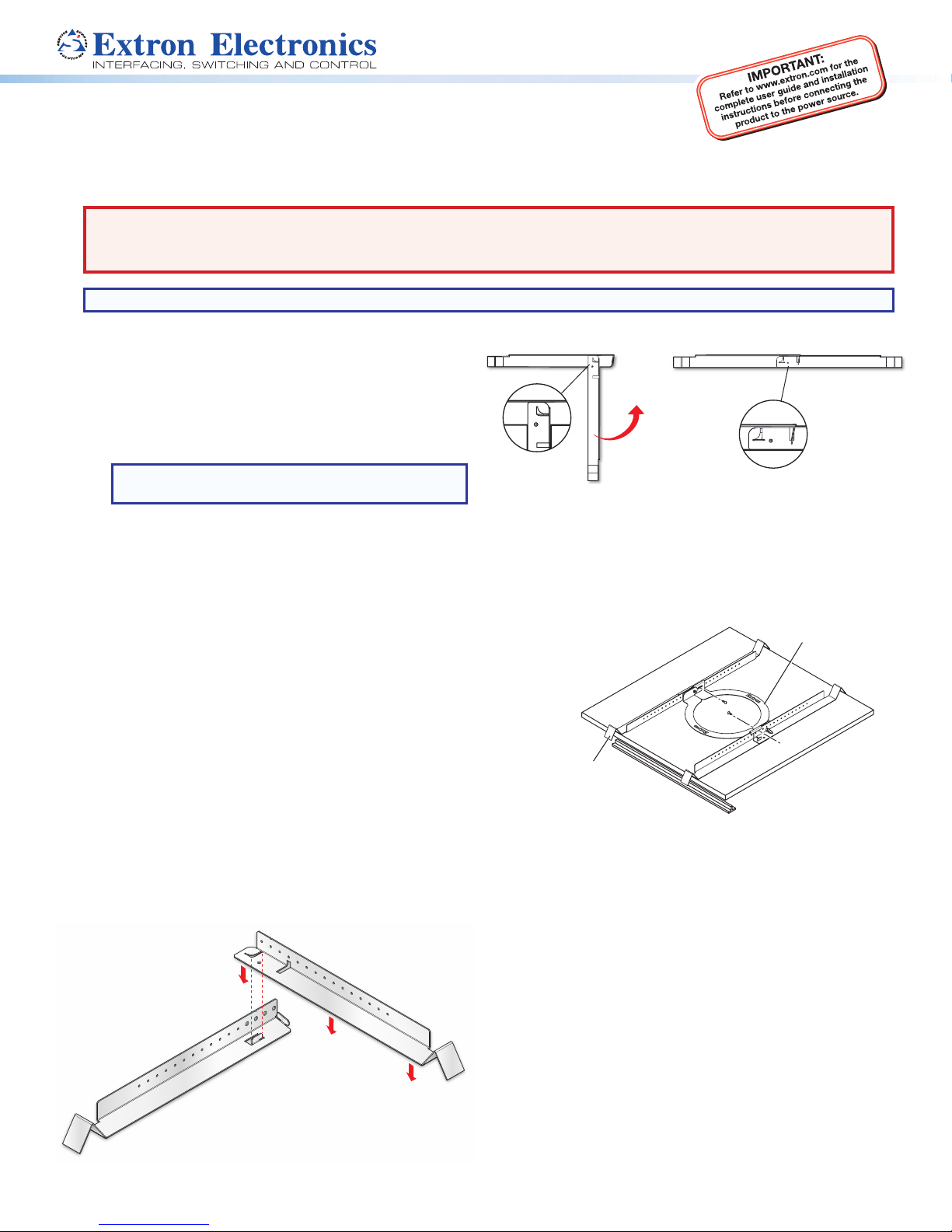
3. Attach two V-rails and one C-ring above the hole cut
in step 2, as described below.
a. Assemble two V-rail half sections so that they
become one single piece by tting the tab of
one end into the slot of the other end. Open the
V-rail until it locks together, as shown. Repeat this
procedure for the other V-rail.
b. Remove a ceiling tile adjacent to the tile with the
hole.
c. Place both assembled V-rails on the cut ceiling tile
and position them equally on either side of the hole.
The ends of the V-rails go over the ceiling grid.
d. Position the C-ring assembly on the two V-rails so
that the C-ring is centered over the hole.
C-ring
-rail
e. Secure the C-ring to the V-rails using two screws.
4. Route the speaker wires through the ceiling tile hole.
5. Configure the terminal cover and captive screw
connector, as described below.
a. The terminal cover has one alternate hole available
covered by a knockout. This hole may be used for
loop out when using conduit. If this knockout needs
to be removed, do the following:
i. With the terminal cover still attached to the
speaker, place the tip of a at-head screwdriver
against the notch of the knockout.
ii. Lightly tap the screwdriver with a hammer to
remove the knockout.
1
Page 2

SF 3C LP and SF 3CT LP • Setup Guide (Continued)
Wiring Multiple Speakers Using Loop-through
b. Loosen the two side terminal cover screws and
remove the cover.
Remove the
terminal cover.
Alternate
Knockout
c. Congure the terminal cover.
When not using conduit:
Route the speaker wires through the cable clamp.
When using conduit:
Remove the cable clamp and install the conduit into
the cover opening. Secure the conduit to the cover
with the locking nut and pull the speaker wires from
the conduit.
d. Strip 0.2 inches (5 mm) from the wire ends.
e. Use one of the following three methods to attach
the speaker wires to the captive screw connector
(depending on the conguration).
When a chain of speakers is wired this way, disconnecting
one speaker removes power from all downstream speakers.
(Red)
1
(Black)
(Red)
(Black)
Power Amplifier
+
–
–
IN
LOOP
IN
Speaker 1
+
LOOP
+
–
–
IN
LOOP
IN
Speaker 2
+
LOOP
Wiring Multiple Speakers in Parallel
When a chain of speakers is wired this way, disconnecting
one speaker does not remove power from the remaining
speakers in the chain.
2
(Red)
(Black)
(Red)
(Black)
(Red)
(Black)
Power Amplifier
+
–
–
IN
LOOP
IN
Speaker 1
+
LOOP
+
–
–
IN
LOOP
IN
Speaker 2
+
LOOP
Wiring a Single Speaker
(Red)
(Black)
3
Wire Gauge Table
Number of Wires per
Connection Point
Power Amplifier
+
–
–
IN
LOOP
IN
Speaker 1
+
LOOP
2
(Red)
(Black)
Maximum
Wire Gauge
1 12 AWG
2 16 AWG
4 18 AWG
Flexible Conduit Adapter
ATTENTION:
• Do not tin the wire leads before installing
into the connector. Tinned wires are not
as secure in the connector and could be
pulled out.
• Ne pas étamer les conducteurs avant de
les insérer dans le connecteur. Les câbles
étamés ne sont pas aussi bien xés dans
le connecteur et pourraient être retirés.
f. Insert the captive screw plug into the four-pole
receptacle of the speaker.
Using a cable clamp:
Using a conduit adapter:
Page 3

g. Replace the terminal cover and tighten the two
8W
16W
100 V
4W
2W
8Ω
8Ω
8W
16W
100 V
4W
2W
8Ω
8Ω
retaining screws.
NOTE: The terminal cover can be positioned
in one of two ways depending on the
application. Flip the cover to the desired
position with the wire openings either on the
side or on the top of the speaker enclosure
before tightening the screws.
100 V
16W
8W
4W
2W
8Ω
8Ω
16W
4W2W1W
8W
70 V
OR
h. Tighten the cable clamp if it was used.
6. Mount the speaker.
a. Insert the speaker through the bottom of the hole in
the ceiling tile that was cut in step 2 with the wires
out of the way.
b. Clamp the speaker to the C-ring by using a Phillips
screwdriver to tighten the three locking arms to the
C-ring.
ATTENTION:
• To avoid damaging the speaker, do not
overtighten the three screws.
• Pour éviter d’endommager l’enceinte, ne
serrez pas trop les trois vis.
7. If required, attach a secondary support line.
a. Connect a secondary support line to the support
loop on the back of the speaker enclosure, as
shown here.
Anchor end to suitable
secure points within the
solid and permanent
building structure.
100 V
16W
8W
4W
2W
8Ω
8Ω
16W
4W2W1W
8W
70 V
Each of the three locking arm screws uses a red
plastic washer that, when tightened to the correct
torque, snaps and separates from its plastic ring.
The plastic washer then falls down the screwdriver
shaft. Stop tightening any further when this occurs
to avoid overtightening the locking arms to the
C-ring.
ATTENTION:
• Do not allow any slack in the secondary
support line.
• Ne laissez pas de mou au niveau du lin de
b. Replace the adjacent tile that was removed in
sécurité secondaire.
step 3.
3
Page 4

SF 3C LP and SF 3CT LP • Setup Guide (Continued)
8. Set the rotary tap selector switch to the appropriate
setting using a small screwdriver.
1
00 V
16W
8W
4W
2W
8Ω
8
Ω
1
4W2W1W8
6W
W
70 V
2W
100 V
4W
8W
16W
Adjust the Tap Selector
9. Install the grille. Position the grille so that it covers the
bafe of the speaker. Six small magnets secure the grille
in place.
16W
8Ω
8W
4W
2W
8Ω
70 V
1W
Speaker Grille
Extron Headquarters
+800.633.9876 Inside USA/Canada Only
Extron USA - West Extron USA - East
+1.714.491.1500 +1.919.850.1000
+1.714.491.1517 FAX +1.919.850.1001 FAX
© 2016 Extron Electronics — All rights reserved. All trademarks mentioned are the property of their respective owners. www.extron.com
4
100 V
16W
8W
4W
2W
8
8
Ω
Ω
1
4W2W1W8
6W
W
70 V
Extron Europe
+800.3987.6673
Inside Europe Only
+31.33.453.4040
+31.33.453.4050 FAX
Extron Asia
+65.6383.4400
+65.6383.4664 FAX
Extron Japan
+81.3.3511.7655
+81.3.3511.7656 FAX
Extron China
+86.21.3760.1568
+86.21.3760.1566 FAX
Extron Middle East
+971.4.299.1800
+971.4.299.1880 FAX
Extron Korea
+82.2.3444.1571
+82.2.3444.1575 FAX
Extron India
1800.3070.3777
(Inside India Only)
+91.80.3055.3777
+91.80.3055.3737 FAX
68-2224-50 Rev. B
06 16
 Loading...