

Page 1
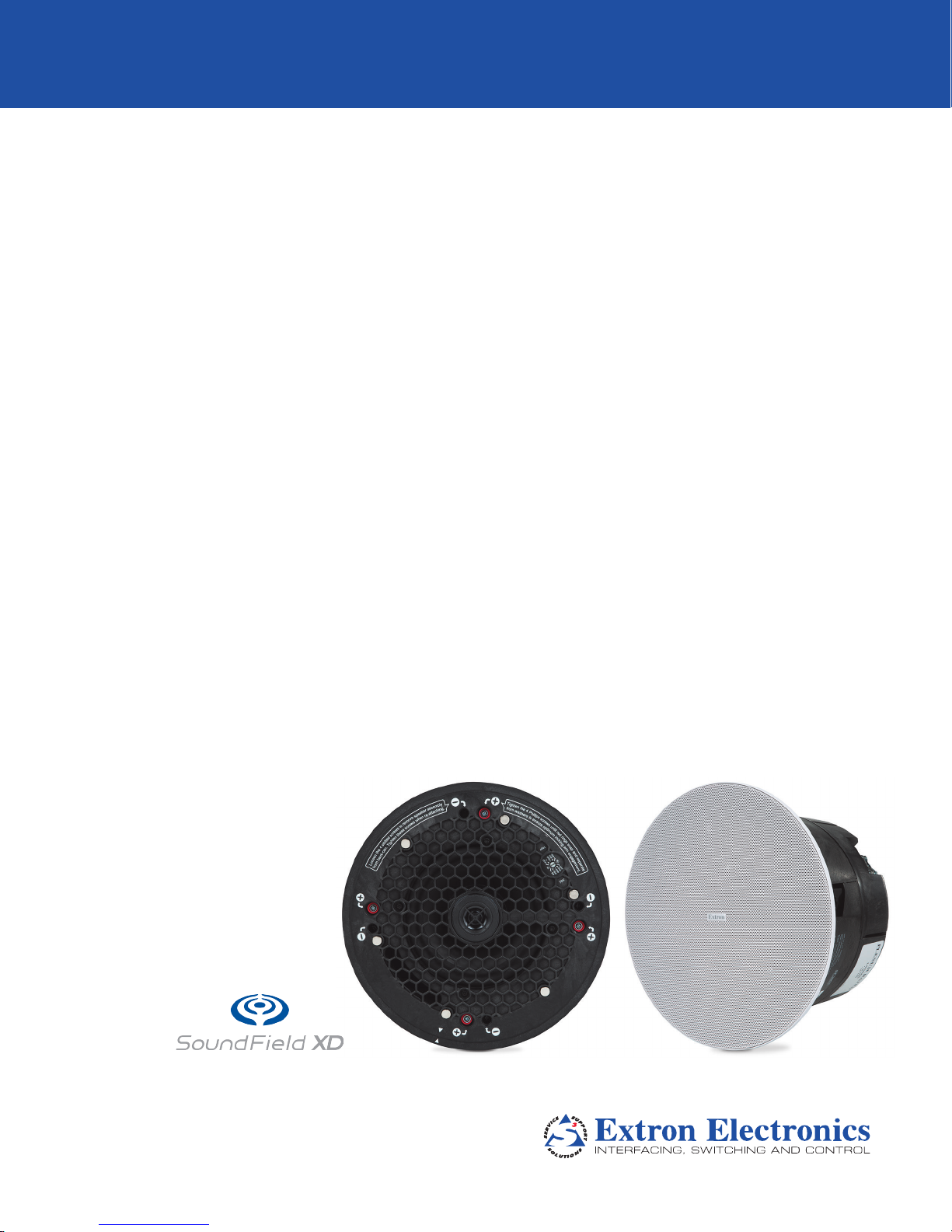
SF 26CT
Two way SoundField® XD Ceiling Speakers with
8" Plastic Back Can
User Guide
Speakers
68-2223-01 Rev. A
12 16
Page 2
Safety Instructions
Safety Instructions • English
WARNING: This symbol, , when used on the product, is intended to
alert the user of the presence of uninsulated dangerous voltage within
the product’s enclosure that may present a risk of electric shock.
ATTENTION: This symbol, , when used on the product, is intended
to alert the user of important operating and maintenance (servicing)
instructions in the literature provided with the equipment.
For information on safety guidelines, regulatory compliances, EMI/EMF
compatibility, accessibility, and related topics, see the Extron Safety and
Regulatory Compliance Guide, part number 68-290-01, on the Extron
website, www.extron.com.
Sicherheitsanweisungen • Deutsch
WARNUNG: Dieses Symbol auf dem Produkt soll den Benutzer
darauf aufmerksam machen, dass im Inneren des Gehäuses dieses
Produktes gefährliche Spannungen herrschen, die nicht isoliert sind und
die einen elektrischen Schlag verursachen können.
VORSICHT: Dieses Symbol auf dem Produkt soll dem Benutzer in
der im Lieferumfang enthaltenen Dokumentation besonders wichtige
Hinweise zur Bedienung und Wartung (Instandhaltung) geben.
Weitere Informationen über die Sicherheitsrichtlinien, Produkthandhabung,
EMI/EMF-Kompatibilität, Zugänglichkeit und verwandte Themen finden Sie in
den Extron-Richtlinien für Sicherheit und Handhabung (Artikelnummer
68-290-01) auf der Extron-Website, www.extron.com.
Instrucciones de seguridad • Español
ADVERTENCIA: Este símbolo, , cuando se utiliza en el producto,
avisa al usuario de la presencia de voltaje peligroso sin aislar dentro del
producto, lo que puede representar un riesgo de descarga eléctrica.
ATENCIÓN: Este símbolo, , cuando se utiliza en el producto, avisa
al usuario de la presencia de importantes instrucciones de uso y
mantenimiento recogidas en la documentación proporcionada con el
equipo.
Para obtener información sobre directrices de seguridad, cumplimiento
de normativas, compatibilidad electromagnética, accesibilidad y temas
relacionados, consulte la Guía de cumplimiento de normativas y seguridad
de Extron, referencia 68-290-01, en el sitio Web de Extron, www.extron.com.
Instructions de sécurité • Français
AVERTISSEMENT : Ce pictogramme, , lorsqu’il est utilisé sur le
produit, signale à l’utilisateur la présence à l’intérieur du boîtier du
produit d’une tension électrique dangereuse susceptible de provoquer
un choc électrique.
ATTENTION : Ce pictogramme, , lorsqu’il est utilisé sur le produit,
signale à l’utilisateur des instructions d’utilisation ou de maintenance
importantes qui se trouvent dans la documentation fournie avec le
matériel.
Pour en savoir plus sur les règles de sécurité, la conformité à la
réglementation, la compatibilité EMI/EMF, l’accessibilité, et autres sujets
connexes, lisez les informations de sécurité et de conformité Extron, réf.
68-290-01, sur le site Extron, www.extron.com.
Istruzioni di sicurezza • Italiano
AVVERTENZA: Il simbolo, , se usato sul prodotto, serve ad
avvertire l’utente della presenza di tensione non isolata pericolosa
all’interno del contenitore del prodotto che può costituire un rischio di
scosse elettriche.
ATTENTZIONE: Il simbolo, , se usato sul prodotto, serve ad
avvertire l’utente della presenza di importanti istruzioni di funzionamento
e manutenzione nella documentazione fornita con l’apparecchio.
Per informazioni su parametri di sicurezza, conformità alle normative,
compatibilità EMI/EMF, accessibilità e argomenti simili, fare riferimento
alla Guida alla conformità normativa e di sicurezza di Extron, cod. articolo
68-290-01, sul sito web di Extron, www.extron.com.
Instrukcje bezpieczeństwa • Polska
OSTRZEŻENIE: Ten symbol, , gdy używany na produkt, ma na celu
poinformować użytkownika o obecności izolowanego i niebezpiecznego
napięcia wewnątrz obudowy produktu, który może stanowić zagrożenie
porażenia prądem elektrycznym.
UWAGI: Ten symbol, , gdy używany na produkt, jest przeznaczony do
ostrzegania użytkownika ważne operacyjne oraz instrukcje konserwacji
(obsługi) w literaturze, wyposażone w sprzęt.
Informacji na temat wytycznych w sprawie bezpieczeństwa, regulacji
wzajemnej zgodności, zgodność EMI/EMF, dostępności i Tematy pokrewne,
zobacz Extron bezpieczeństwa i regulacyjnego zgodności przewodnik, część
numer 68-290-01, na stronie internetowej Extron, www.extron.com.
Инструкция по технике безопасности • Русский
ПРЕДУПРЕЖДЕНИЕ: Данный символ, , если указан на продукте,
предупреждает пользователя о наличии неизолированного опасного
напряжения внутри корпуса продукта, которое может привести к поражению
электрическим током.
ВНИМАНИЕ: Данный символ, , если указан на продукте,
предупреждает пользователя о наличии важных инструкций
по эксплуатации и обслуживанию в руководстве,
прилагаемом к данному оборудованию.
Для получения информации о правилах техники безопасности,
соблюдении нормативных требований, электромагнитной
совместимости (ЭМП/ЭДС), возможности доступа и других
вопросах см. руководство по безопасности и соблюдению
нормативных требований Extron на сайте Extron: ,
www.extron.com, номер по каталогу - 68-290-01.
安全说明 • 简体中文
警告: 产品上的这个标志意在警告用户该产品机壳内有暴露的危险 电压,
有触电危险。
注意: 产品上的这个标志意在提示用户设备随附的用户手册中有
重要的操作和维护(维修)说明。
关于我们产品的安全指南、遵循的规范、EMI/EMF 的兼容性、无障碍
使用的特性等相关内容,敬请访问 Extron 网站 , www.extron.com,参见
Extron 安全规范指南,产品编号 68-290-01。
Page 3
安全記事 • 繁體中文
警告: 若產品上使用此 符號,是為了提醒使用者,產品機殼內存在著
可能會導致觸電之風險的未絕緣危險電壓。
注意 若產品上使用此符號,是為了提醒使用者,設備隨附的用戶手冊中有
重要的操作和維護(維修)説明。
有關安全性指導方針、法規遵守、EMI/EMF 相容性、存取範圍和相關主題的詳細資
訊,請瀏覽 Extron 網站:www.extron.com,然後參閱《Extron 安全性與法規
遵守手冊》,準則編號 68-290-01。
安全上のご注意 • 日本語
警告: この記 号 が製品上に表示されている場合は、筐体内に絶縁されて
いない高電圧が流れ、感電の危険があることを示しています。
注意:この記号 が製品上に表示されている場合は、本機の取扱説明書に
記載されている重要な操作と保守( 整備)の 指示についてユーザーの注 意
を喚起するものです。
安全上のご注意、法規厳守、EMI/EMF適合性、その他の関連項目に
つ い て は 、エ ク ストロ ン の ウェブ サ イト www.extron.com よ り 『 Extron Safety
and Regulatory Compliance Guide』 ( P/N 68-290-01) をご覧ください。
안전 지침 • 한국어
경고: 이 기호 가 제품에 사용될 경우, 제품의 인클로저 내에 있는
접지되지 않은 위험한 전류로 인해 사용자가 감전될 위험이 있음을
경고합니다.
주의: 이 기호 가 제품에 사용될 경우, 장비와 함께 제공된 책자에 나와
있는 주요 운영 및 유지보수(정비) 지침을 경고합니다.
안전 가이드라인, 규제 준수, EMI/EMF 호환성, 접근성, 그리고 관련 항목에
대한 자세한 내용은 Extron 웹 사이트(www.extron.com)의 Extron 안전 및
규제 준수 안내서, 68-290-01 조항을 참조하십시오.
Copyright
© 2016 Extron Electronics. All rights reserved.
Trademarks
All trademarks mentioned in this guide are the properties of their respective owners.
The following registered trademarks(
®
), registered service marks(
ExtronElectronics (see the current list of trademarks on the Terms of Use page at www.extron.com):
Extron, AVTrac, Cable Cubby, ControlScript, CrossPoint, DTP, eBUS, EDID Manager, EDID Minder, Flat Field, FlexOS, Global Configurator,
GlobalScripter, GlobalViewer, Hideaway, Inline, IPIntercom, IPLink, KeyMinder, LinkLicense, LockIt, MediaLink, MediaPort, NetPA,
PlenumVault, PoleVault, PowerCage, PURE3, Quantum, SoundField, SpeedMount, SpeedSwitch, SystemINTEGRATOR, TeamWork,
TouchLink, V-Lock, VersaTools, VN-Matrix, VoiceLift, WallVault, WindoWall, XTP, and XTPSystems
Registered Service Mark
(SM)
: S3 Service Support Solutions
AAP, AFL (Accu-RateFrameLock), ADSP(Advanced Digital Sync Processing), Auto-Image, CableCover, CDRS(ClassD Ripple
Suppression), DDSP(Digital Display Sync Processing), DMI (DynamicMotionInterpolation), DriverConfigurator, DSPConfigurator,
DSVP(Digital Sync Validation Processing), eLink, Entwine, EQIP, FastBite, FOX, FOXBOX, IP Intercom HelpDesk, MAAP, MicroDigital,
Opti-Torque, ProDSP, QS-FPC(QuickSwitch Front Panel Controller), Room Agent, Scope-Trigger, ShareLink, SIS, SimpleInstructionSet,
Skew-Free, SpeedNav, Triple-Action Switching, True4K, Vector™ 4K , WebShare, XTRA, ZipCaddy, and ZipClip
SM
), and trademarks(TM) are the property of RGBSystems, Inc. or
Registered Trademarks
Trademarks (™
)
(®)
Page 4
FCC Class A Notice
This equipment has been tested and found to comply with the limits for a Class A digital device,
pursuant to part15 of the FCC rules. The ClassA limits provide reasonable protection against harmful
interference when the equipment is operated in a commercial environment. This equipment generates,
uses, and can radiate radio frequency energy and, if not installed and used in accordance with the
instruction manual, may cause harmful interference to radio communications. Operation of this
equipment in a residential area is likely to cause interference; the user must correct the interference at
his own expense.
NOTE: This unit was tested with shielded I/O cables on the peripheral devices. Shielded cables
must be used to ensure compliance with FCC emissions limits.
For more information on safety guidelines, regulatory compliances, EMI/EMF compatibility,
accessibility, and related topics, see the “Extron Safety and Regulatory Compliance Guide”
on the Extron website.
Conventions Used in this Guide
Notifications
The following notifications are used in this guide:
WARNING: Potential risk of severe injury or death.
AVERTISSEMENT : Risque potentiel de blessure grave ou de mort.
ATTENTION:
NOTE: A note draws attention to important information.
Specifications Availability
Product specifications are available on the Extron website, www.extron.com.
• Risk of property damage.
• Risque de dommages matériels.
Page 5

Contents
Introduction............................................................ 1
Overview ............................................................ 1
Features ............................................................. 1
Application Example ........................................... 2
Installation in a Suspended Ceiling
(Single Installer) .................................................... 3
Installation Considerations .................................. 3
Preparing the Installation Location ...................... 3
Configuring the Speaker ..................................... 5
Mounting the Speaker ........................................ 7
Installation in a Suspended Ceiling
(Division of Labor) .............................................. 11
Getting Started ................................................. 11
Preparing the Installation Location .................... 12
Configuring the Speaker ................................... 12
Mounting the Speaker ...................................... 13
Installation in a Hard Ceiling ............................ 18
Preparing the Installation Location .................... 18
Configuring the Speaker ................................... 18
Mounting the Speaker ...................................... 19
Reference Information ...................................... 22
Painting the Speaker Grille ................................ 22
Troubleshooting ................................................ 23
Testing Source Signal (all configurations) ....... 23
Testing the Impedance (Loop-Through
Configuration Only) ...................................... 23
SF 26CT User Guide • Contents v
Page 6

SF 26CT User Guide • Contents vi
Page 7

Introduction
This section gives an overview of the Extron SF 26CT SoundField® XD 2-way speaker.
Topics include:
• Overview
• Features
• Application Example
Overview
The Extron SoundField® XD SF 26CT is a two-way ceiling speaker featuring an 8" (10.2 cm)
composite back can for use in plenum rated ceiling environments. With the industry’s first
UL 2043 listed composite speaker enclosure, the SF 26CT meets stringent UL requirements
for smoke and heat release in plenum air spaces. The SF 26CT features a 6.5" woofer and
3/4" tweeter. Its coverage angle is 111°. It has a frequency range of 65 Hz to 20 kHz.
Features
• 8" (20.3 cm) deep composite back can for plenum environments
• 3/4" (1.9 cm) ferrofluid-cooled dome tweeter
• 6.5" (16.5 cm) long throw woofer with a tuned bass reflex enclosure
• Frequency range: 65 Hz to 22 kHz, -10 dB, half space
• 111° conical dispersion
• 65 watts continuous pink noise, 130 watts continuous program
• 8 ohm direct or 70/100 volt operation on a 6 position, behind-the-grille selector
• 8 ohm direct
• 70 volt: 64, 32, 16, and 8 watt selectable
• 100 volt: 64, 32, and 16 watt selectable
• Magnetically attached grille with a thin bezel for a refined appearance
• Grille and bezel are white and can be painted to match any environment
• Separable back can and baffle supports both single-trade and division-of-labor
applications
• Modular V-rail and folding C-ring kit included
• Cable/conduit access plate can be oriented for side or top connections
• Opti-Torque indicator rings prevent overtightening of locking arm screws
• Four locking arms for quick ceiling installation
• UL 2043 plenum rated enclosure
• 5-year parts and labor warranty
SF 26CT User Guide • Introduction 1
Page 8
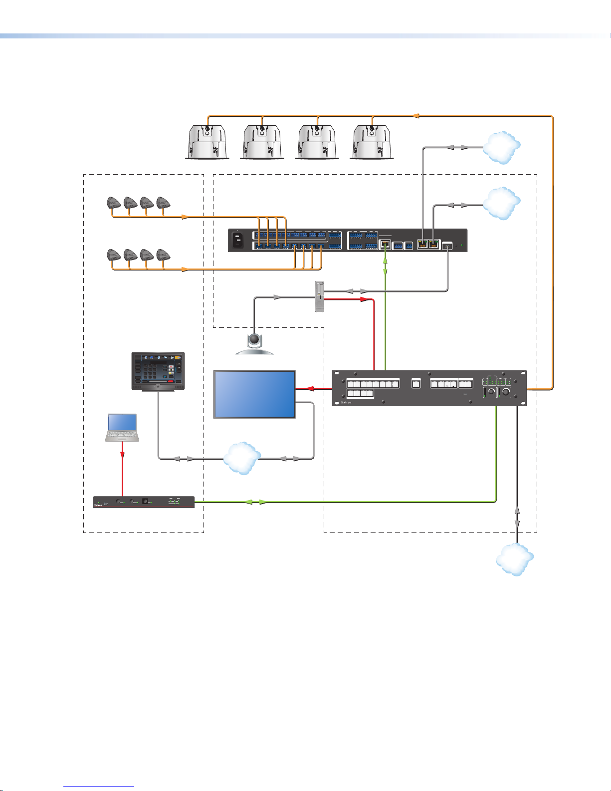
Application Example
The application diagram below shows one way to configure a system using the SF 26CT.
Audio
Extron
SF 26CT
Full-Range Ceiling Speakers
Conference Table Credenza
•
•
•
•
P
U
•
H
S
Tab le
Microphones
•
P
U
•
H
S
Laptop
P
P
U
•
H
S
•
P
U
•
H
S
Extron
TLP Pro 1020T
10" Tabletop
TouchLink Pr o
Touchpanel
P
U
U
•
•
H
H
S
S
•
•
P
P
U
U
•
•
H
H
S
S
VCRLaptop PC DVD
Display
Tuner
On
Channel
321
Off
654
Mute
987
Room
Last
Control
Enter
0
Screen
Lighting
December 15, 2013 - 7:58 AM
Help
100-240V 0.7A MAX
50 - 60 Hz
Doc
Tuner
1 2 3
Cam
Volume
Presets
Mute
More
Presets
System
Audio
Control
Off
Camera
Flat Panel Display
Extron
Audio
DMP 128 Pl us C V
Digital Matrix Processor
I/O
GIN1O1O2 GIN2O1O2 GIN3O1O2 GIN4O1O2 GIN5O1O2 GIN6O1O2 GIN7O1O2 GIN8O1O2
1 2 3 4 5 6 7 8
INPUTS
Audio
USB Video
HDMI
9 10
11 12
3
4
1 2
DMP 128 Plus C V
7 8
5 6
OUTPUTS
DMP EXP
DMP EXP
WiFi
123 4
USB Audio
HDMI
PC
INPUTS
2
1
4
7
3
6
5
2
1
3 4
OUTPUTS
Extron
DTP CrossPoint 82 4K IP CP MA
Scaling Presentation Matrix Switcher
Ethernet
Ethernet
RS-232
ACP
REMOTE
+S+V -S G
RxTx G
8
USB AUDIO
RESET
LAN/VoIP
2 1
CONTROL I/O
LOGO
SELECT
ENTER PRESET
ESC
VIDEO
VIEW
CONFIG
VoIP
LAN
COM
RTS
eBUS
IR/S I/O
RELAYS
CTS
S LIMIT
1 1 2
1 2
Tx
Rx
AUDIO
OVER
1 2 23 3 4
3 4
MIC VOLUME VOLUME
DTP CROSSPOINT 4K SERIES
DIGITAL PRESENTATION SWITCHER
HDMI
AUTO
SWITCH
CONFIG
Extron
DTP T USW 233
Transmitter
1
2 3
AUTO
MODE
NORMAL
Ethernet
STATUS
1 2 3
SIGNAL
HDCP
DTP T USW 233
LAN
Cat 5/5e/6/ 7
Ethernet
Ethernet
LAN
Figure 1. SF 26CT Application Diagram
SF 26CT User Guide • Introduction 2
Page 9

Installation in a
Suspended Ceiling
(Single Installer)
If a single installer is installing the SF 26CT speaker system, follow the steps in this section.
Topics in this section include:
• Installation Considerations
• Preparing the Installation Location
• Configuring the Speaker
• Mounting the Speaker
Installation Considerations
WARNING: Potential risk of severe injury. Installation and service must be
performed by authorized personnel only.
AVERTISSEMENT : Risque potentiel de blessure grave ou de mort. L’installation
et l’entretien doivent être effectués par le personnel autorisé uniquement.
• All wiring and electrical connections must conform to all applicable building codes and
local ordinances.
• Installation in a plenum-rated environment requires plenum rated cable or conduit.
• If using secondary support cables, the installer provides the cables.
Preparing the Installation Location
1. Power down all attached devices before proceeding.
2. Ensure that there is sufficient clearance above the ceiling tile for the unit to be installed.
3. Cut a hole for the speaker. Use the provided cutout template to outline the hole to be
cut in the ceiling tile as described below.
a. Remove the ceiling tile.
b. To find the center of the tile, use a tape measure to measure the space between
two opposite corners, and mark the half-way point.
c. Position the center hole of the cutout template directly over the
center of the tile that you marked in step3b.
d. Using the provided cutout template, trace a circle around the
cutout template.
e. Cut out the circle traced in the ceiling tile.
f. Replace the tile in the ceiling.
SF 26CT User Guide • Installation - Single Installer 3
Page 10

4. Attach two V-rails and one C-ring across the tile above the hole cut in step 3, as shown
V
below:
a. Assemble two V-rail half sections as follows: fit the tab of one end into the slot of
the other end, then open the V-rail until it locks together (see figure 2). Repeat this
procedure for the other V-rail.
Figure 2. Assembling the V-rails
b. Remove a ceiling tile adjacent to the tile with the hole.
c. Place both assembled V-rails on the cut ceiling tile and position them equally on
either side of the hole. The ends of the V-rails go over the ceiling grid.
d. Position the C-ring assembly on the two V-rails so that the C-ring is centered over
the hole, as shown below.
C-ring
-rail
Figure 3. Positioning the C-ring assembly on the V-rails
e. Secure the C-ring to the V-rails using two screws.
5. Route the speaker wires through the ceiling tile hole.
SF 26CT User Guide • Installation - Single Installer 4
Page 11

Configuring the Speaker
Speaker 1
Speaker 2
IN
–
LOOP
–
IN
+
LOOP
+
(Black)
(Red)
(Red)
(Red)
(Black)
(Black)
Power Amplier
IN
–
LOOP
–
IN
+
LOOP
+
Wiring Multiple Speakers Using Loop-through
When a chain of speakers is wired this way, disconnecting
one speaker removes power from all downstream speakers.
1
2
Configure the cable/conduit access plate and captive screw connector as follows.
1. Loosen the two side access plate screws and remove the plate before wiring the
speaker.
Cable/conduit
access plate
Screws (2)
Cable
clamp
Alternate
knockout
Figure 4. Removing the cable/conduit access plate
2. Configure the access plate:
• If not using conduit: Route the speaker wires through the cable clamp.
• If using conduit: Remove the cable clamp and install the conduit into the plate
opening. Secure the conduit to the plate with the locking nut and pull the speaker
wires from the conduit.
NOTE: The cover plate has an alternate hole available by removing the knockout.
3. Strip 0.2 inches (5 mm) from the wire ends.
4. Attach the speaker wires to the captive screw connector depending on the
configuration, as illustrated by the following three methods.
Wiring Multiple Speakers Using Loop-through
When a chain of speakers is wired this way, disconnecting
one speaker removes power from all downstream speakers.
1
Power Amplier
(Red)
(Black)
+
–
–
IN
LOOP
IN
Speaker 1
(Red)
(Black)
+
LOOP
–
–
LOOP
IN
Speaker 2
(Red)
(Black)
+
+
IN
LOOP
Wiring Multiple Speakers in Parallel
When a chain of speakers is wired this way, disconnecting
one speaker does not remove power from the remaining
speakers in the chain.
(Red)
(Black)
+
+
IN
LOOP
IN
Power Amplier
(Red)
(Black)
+
–
–
IN
LOOP
IN
Speaker 1
(Red)
(Black)
+
LOOP
–
–
LOOP
Speaker 2
SF 26CT User Guide • Installation - Single Installer 5
Page 12

Wiring Multiple Speakers in Parallel
When a chain of speakers is wired this way, disconnecting
one speaker does not remove power from the remaining
speakers in the chain.
Speaker 1
Speaker 2
IN
–
LOOP
–
IN
+
LOOP
+
(Black)
(Red)
(Red)
(Red)
(Black)
(Black)
Power Amplier
Speaker 1
Speaker 2
(Black)
(Red)
(Red)
(Black)
Power Amplier
(Black)
(Red)
IN
–
LOOP
–
IN
+
LOOP
+
IN
–
LOOP
–
IN
+
LOOP
+
IN
–
LOOP
–
IN
+
LOOP
+
Wiring Multiple Speakers Using Loop-through
When a chain of speakers is wired this way, disconnecting
one speaker removes power from all downstream speakers.
1
2
3
Flexible Conduit Adapter
Wiring a Single Speaker
(Red)
(Black)
Number of Wires per
Connection Point
Wire Gauge Table
Maximum
Wire Gauge
1 12 AWG
2 16 AWG
4 18 AWG
Power Amplier
+
–
–
IN
LOOP
IN
Speaker 1
+
LOOP
ATTENTION:
• Do not tin the wire leads before installing into the connector. Tinned wires
are not as secure in the connector and could be pulled out.
• Ne pas étamer les conducteurs avant de les insérer dans le connecteur.
Les câbles étamés ne sont pas aussi bien xés dans le connecteur et
pourraient être retirés.
5. Insert the captive screw plug into the four-pole receptacle of the speaker.
• Using a cable clamp on the access plate:
Figure 5. Using a cable clamp
• Using a conduit adapter on the access plate:
Figure 6. Using a conduit adapter
SF 26CT User Guide • Installation - Single Installer 6
Page 13

6. Replace the access plate and tighten the two retaining screws.
m
NOTE: The access plate can be positioned in one of two ways depending on
Before tightening the screws, flip the cover to the desired position with the wire
7. Tighten the cable clamp if it was used.
Mounting the Speaker
installer preference. For example:
• The side access wire opening may be useful when space above the ceiling is
limited.
• The top access wire opening may be more convenient to use.
OR
openings either on the side or on the top of the speaker enclosure.
1. Insert the speaker through the bottom of the hole in the ceiling tile that was cut in
step 3 on page 3 (“Preparing the Installation Location”) with the wires out of the way.
2. Clamp the speaker to the C-ring by using a Phillips screwdriver to tighten the four
locking arms to the C-ring (see figure 7 below and the Note on the next page).
NOTE: The screw hole locations are marked on the
front baffle with a Phillips-head screw symbol.
Use these holes to tighten the locking arms.
Locking ar
screw hole
marking
7
0 V
8W
32W
64W
16W
OFF
Ω
8Ω
8
OFF
64W
16W
32W
10
0
V
Figure 7. Clamping the speaker to the C-ring
SF 26CT User Guide • Installation - Single Installer 7
Page 14

NOTE: Each of the four locking arm screws uses an Opti-TorqueTM indicator. The
e
indicator releases a red plastic ring onto the screwdriver once the screw is
tightened to the correct torque. Stop tightening any further when this occurs to
avoid overtightening the locking arms to the C-ring.
70 V
8W
32W
64W
16W
OFF
8Ω
8Ω
OFF
64W
16W
32W
100 V
Figure 8. Stop tightening when the red ring falls
ATTENTION:
• To avoid damaging the speaker, do not overtighten the four screws.
• Pour éviter d’endommager l’enceinte, ne serrez pas trop les quatre vis.
3. If required, attach a secondary support line.
a. Connect a secondary support line to the support loop on the back of the speaker
enclosure, as shown here.
Anchor end to suitable
secure points within th
solid and permanent
building structure.
Figure 9. Connecting a secondary support line
ATTENTION:
• Do not allow any slack in the secondary support line.
• Ne laissez pas de mou au niveau du filin de sécurité secondaire.
b. Replace the adjacent ceiling tile that was removed in step 4b on page 4.
SF 26CT User Guide • Installation - Single Installer 8
Page 15

4. Set the rotary tap selector switch to the appropriate setting using a small screwdriver.
8Ω
8Ω
64W
32W
OFF
8W
16W
64W
32W
16W
OFF
100 V
70 V
ATTENTION:
• When setting the taps for a distributed (high impedance) system, do not tap
the system above the rated power of the amplifier.
• Lors de la mise en place des capteurs pour un système distribué (haute
impédance), n’exploitez pas le système au delà du niveau d’alimentation de
l’amplificateur.
• When connecting multiple speakers in 8-ohm mode, be sure that the combined
rated impedance does not equal a value less than the minimum rated
impedance of the amplifier.
• Lors de la connexion de plusieurs enceintes en mode 8ohm, assurez vous que
le niveau d’impédance combinée ne soit pas équivalent à une valeur inférieure
à l’impédance minimum de l’amplificateur.
Adjust the Tap Selector
7
0 V
F
W
W
W
W
F
2
4
6
8
3
6
1
O
Ω
Ω
8
8
F
W
W
W
F
4
6
2
O
6
1
3
100
V
Figure 10. Setting the rotary tap selector switch
SF 26CT User Guide • Installation - Single Installer 9
Page 16

5. Install the grille. Position the grille so that it covers the baffle of the speaker. Six small
magnets secure the grille in place.
70 V
F
W
W
W
W
F
2
4
6
8
3
6
1
O
Ω
Ω
8
8
F
W
W
W
F
4
6
2
O
6
1
3
100
V
Speaker Grille
Figure 11. Installing the grille
NOTE: Specific test points can be used to troubleshoot speaker system problems (see
Troubleshooting on page 23).
SF 26CT User Guide • Installation - Single Installer 10
Page 17

Installation in a
Suspended Ceiling
(Division of Labor)
For a division of labor installation, follow the steps in this section. In a division of labor
installation, low-voltage contractors first install the speaker back can enclosure (construction
rough-in phase). After the back can has been installed, the second phase of the installation
can begin by installing the speaker assembly to the back can.
Topics in this section include:
• Getting Started
• Preparing the Installation Location
• Configuring the Speaker
• Mounting the Speaker
Getting Started
1. Using a flat head screwdriver, completely loosen the four screws holding the speaker
assembly to the back can enclosure from the speaker, as shown below.
NOTE: The screws are not removable. They will unscrew completely, but will not
pull out.
0 V
0
1
3
1
6
OF
2W
6W
4W
F
8Ω
8Ω
OFF
16W
64W
3
8
2W
W
0 V
7
NOTE: Notches are provided to help pry the
speaker assembly from the back can.
Figure 12. Unscrewing the speaker assembly from the back can
SF 26CT User Guide • Installation in a Suspended Ceiling - Division of Labor 11
Page 18

2. Carefully separate the speaker assembly from the back can, as shown below.
NOTE: Disconnect the speaker wires from the speaker assembly before completely
separating the speaker assembly from the back can.
Figure 13. Separating the speaker assembly from the back can
3. Repeat steps 1 and 2 for each speaker in the system and distribute the
components to the appropriate installers.
Preparing the Installation Location
Follow the steps in Preparing the Installation Location on page 3.
Configuring the Speaker
Follow the steps in Configuring the Speaker on page 5.
SF 26CT User Guide • Installation in a Suspended Ceiling - Division of Labor 12
Page 19

Mounting the Speaker
1. Mount the speaker back can enclosure.
a. Insert the speaker through the bottom of the hole in the ceiling tile that was cut with
the wires out of the way.
Figure 14. Inserting the speaker back can
b. Clamp the speaker back can to the C-ring by using a Phillips screwdriver to tighten
the four locking arms to the C-ring.
Figure 15. Tightening the locking arms
SF 26CT User Guide • Installation in a Suspended Ceiling - Division of Labor 13
Page 20

NOTE: Each of the four locking arm screws uses an Opti-TorqueTM indicator.
e
The indicator releases a red plastic ring onto the screwdriver once the screw
is tightened to the correct torque. Stop tightening any further when this
occurs to avoid overtightening the locking arms to the C-ring.
Figure 16. Stop tightening when the red ring falls
ATTENTION:
• To avoid damaging the speaker, do not overtighten the four screws.
• Pour éviter d’endommager l’enceinte, ne serrez pas trop les quatre vis.
2. If required, attach a secondary support line.
a. Connect a secondary support line to the support loop on the the back of the
speaker enclosure, as shown here.
Anchor end to suitable
secure points within th
solid and permanent
building structure.
Figure 17. Connecting a secondary support line
ATTENTION:
• Do not allow any slack in the secondary support line.
• Ne laissez pas de mou au niveau du filin de sécurité secondaire.
b. Replace the adjacent ceiling tile that was removed in step 4b on page 4.
3. Repeat steps 1 and 2 for each speaker being installed.
SF 26CT User Guide • Installation in a Suspended Ceiling - Division of Labor 14
Page 21

4. Attach the speaker assembly to the back can enclosure.
a. Connect the speaker wires from the back can enclosure to the speaker assembly.
70 V
8W
32W
16W
64W
OFF
Ω
8Ω
8
OFF
64W
16W
32W
10
0
V
Figure 18. Connecting speaker wires to the speaker assembly
b. Rotate the speaker assembly so that the white arrows on the back can enclosure
and the speaker assembly are aligned with each other, and insert the speaker into
the back can. Make sure that the speaker wires do not get in the way or become
pinched.
c. Using a flat head screwdriver, tighten the four screws that attach the speaker
assembly to the back can.
7
0 V
8W
32W
64W
16W
OFF
Ω
8Ω
8
OFF
64W
16W
32W
1
00
V
Figure 19. Clamping the speaker to the C-ring
ATTENTION:
• To avoid damaging the speaker, do not overtighten the four screws.
• Pour éviter d’endommager l’enceinte, ne serrez pas trop les quatre vis.
SF 26CT User Guide • Installation in a Suspended Ceiling - Division of Labor 15
Page 22

5. Set the rotary tap selector switch to the appropriate setting using a small screwdriver
8Ω
8Ω
64W
32W
OFF
8W
16W
64W
32W
16W
OFF
100 V
70 V
(see figure 20).
ATTENTION:
• When setting the taps for a distributed (high impedance) system, do not tap
the system above the rated power of the amplifier.
• Lors de la mise en place des capteurs pour un système distribué (haute
impédance), n’exploitez pas le système au delà du niveau d’alimentation de
l’amplificateur.
• When connecting multiple speakers in 8-ohm mode, be sure that the combined
rated impedance does not equal a value less than the minimum rated
impedance of the amplifier.
• Lors de la connexion de plusieurs enceintes en mode 8ohm, assurez vous que
le niveau d’impédance combinée ne soit pas équivalent à une valeur inférieure
à l’impédance minimum de l’amplificateur.
Adjust the Tap Selector
7
0 V
F
W
W
W
W
F
2
4
6
8
3
6
1
O
Ω
Ω
8
8
F
W
W
W
F
4
6
2
O
6
1
3
100
V
Figure 20. Setting the rotary tap selector switch
SF 26CT User Guide • Installation in a Suspended Ceiling - Division of Labor 16
Page 23

6. Install the grille. Position the grille so that it covers the baffle of the speaker. Six small
magnets secure the grille in place.
70 V
F
W
W
W
W
F
2
4
6
8
3
6
1
O
Ω
Ω
8
8
F
W
W
W
F
4
6
2
O
6
1
3
100
V
Speaker Grille
Figure 21. Installing the grille
NOTE: Specific test points can be used to troubleshoot speaker system problems (see
Troubleshooting on page 23).
SF 26CT User Guide • Installation in a Suspended Ceiling - Division of Labor 17
Page 24

Installation in a
Hard Ceiling
To install the SF 26CT in a hard ceiling (having no ceiling tiles), with the ceiling structure in
place, follow the steps in this section.
Topics in this section include:
• Preparing the Installation Location
• Configuring the Speaker
• Mounting the Speaker
Preparing the Installation Location
1. Power down all attached devices before proceeding.
2. Cut a hole for the speaker. Use the provided cutout template to outline the hole to be
cut in the ceiling as described below.
a. Mark the location on the ceiling where the center of the speaker will be placed.
b. Position the center hole of the cutout template directly over the center mark.
c. Trace a circle around the cutout template.
d. Cut out the traced circle.
3. Fold one C-ring assembly in half and insert it through the hole in the ceiling.
4. Unfold the C-ring and center it over the hole with the flat side down.
Figure 22. Installing the C-ring
5. Route the speaker wires through the ceiling hole.
Configuring the Speaker
Follow the steps in Configuring the Speaker on page 5.
SF 26CT User Guide • Installation in a Hard Ceiling 18
Page 25

Mounting the Speaker
e
1. If required, attach a secondary support line.
Connect a secondary support line to the support loop on the back of the speaker
enclosure, as shown here.
Figure 23. Connecting a secondary support line
2. With the wires out of the way, insert the speaker through the bottom of the hole in the
ceiling that was cut in step 2 on page 18.
3. Clamp the speaker to the C-ring by using a Phillips screwdriver to tighten the four
locking arms to the C-ring.
Anchor end to suitable
secure points within th
solid and permanent
building structure.
7
0 V
8W
32W
64W
16W
OFF
Ω
8Ω
8
OFF
64W
16W
32W
10
0
V
Figure 24. Clamping the speaker to the C-ring
SF 26CT User Guide • SF 26CT User Guide • Installation in a Hard Ceiling 19
Page 26

NOTE: Each of the four locking arm screws uses an Opti-TorqueTM indicator. The
indicator releases a red plastic ring onto the screwdriver once the screw is
tightened to the correct torque. Stop tightening any further when this occurs to
avoid overtightening the locking arms to the C-ring.
70 V
8W
32W
64W
16W
OFF
8Ω
8Ω
OFF
64W
16W
32W
100 V
Figure 25. Stop tightening when the red ring falls
ATTENTION:
• To avoid damaging the speaker, do not overtighten the four screws.
• Pour éviter d’endommager l’enceinte, ne serrez pas trop les quatre vis.
4. Set the rotary tap selector switch to the appropriate setting using a small screwdriver
(see figure 26 on the next page).
ATTENTION:
• When setting the taps for a distributed (high impedance) system, do not tap
the system above the rated power of the amplifier.
• Lors de la mise en place des capteurs pour un système distribué (haute
impédance), n’exploitez pas le système au delà du niveau d’alimentation de
l’amplificateur.
• When connecting multiple speakers in 8-ohm mode, be sure that the combined
rated impedance does not equal a value less than the minimum rated
impedance of the amplifier.
• Lors de la connexion de plusieurs enceintes en mode 8ohm, assurez vous que
le niveau d’impédance combinée ne soit pas équivalent à une valeur inférieure
à l’impédance minimum de l’amplificateur.
SF 26CT User Guide • SF 26CT User Guide • Installation in a Hard Ceiling 20
Page 27

Adjust the Tap Selector
8Ω
8Ω
64W
32W
OFF
8W
16W
64W
32W
16W
OFF
100 V
70 V
7
0 V
F
W
W
W
W
F
2
4
6
8
3
6
1
O
Ω
Ω
8
8
F
W
W
W
F
4
6
2
O
6
1
3
100
V
Figure 26. Setting the rotary tap selector switch
5. Install the grille. Position the grille so that it covers the baffle of the speaker. Six small
magnets secure the grille in place.
70 V
F
W
W
W
W
F
2
4
6
8
3
6
1
O
Ω
Ω
8
8
F
W
W
W
F
4
6
2
O
6
1
3
100
V
Speaker Grille
Figure 27. Installing the grille
NOTE: Specific test points can be used to troubleshoot speaker system problems (see
Troubleshooting on page 23).
SF 26CT User Guide • SF 26CT User Guide • Installation in a Hard Ceiling 21
Page 28

Reference
Information
This section covers the following topics:
• Painting the Speaker Grille
• Troubleshooting
Painting the Speaker Grille
The speaker grille can be painted using spray paint. Ensure that the spray paint adheres to
both metal and plastic.
NOTE: Extron is not responsible for any alterations to the original paint.
To paint the grille:
1. Remove the grille from the speaker.
7
0 V
F
W
W
W
W
F
2
4
6
8
3
6
1
O
Ω
Ω
8
8
F
W
W
W
F
4
6
2
O
6
1
3
100
V
Speaker Grille
Figure 28. SF 26CT Speaker Grille
2. Remove and set aside the scrim from the back side of the grille.
3. Spray paint the front side of the grille.
NOTES:
• Do not paint the back side of the grille.
• Apply an even coat across the entire front surface.
• Be sure not to clog the grille holes.
4. Wait for the paint to dry.
5. Reattach the scrim to the back of the grille.
6. Reattach the grille to the speaker.
SF 26CT User Guide • Reference Information 22
Page 29

Troubleshooting
Test Points
Testing Source Signal (all configurations)
The following signal test points can be used to troubleshoot speaker system problems.
The source signal can be tested by connecting to the inner + (IN) and – (IN) terminals of the
captive screw connector.
Red Wire (+) from Amplifier
Amplifier
Black Wire (-) from Amplifier
Test Points
Figure 29. Signal Test Points — Parallel Configuration
Testing the Impedance (Loop-Through Configuration Only)
The impedance of the speakers downstream of the one being tested can be measured
while the system is on. To do this, connect to the outer (LOOP) terminals of the captive
screw connector, as shown below.
Red Wire (+) from Amplifier
Amplifier
Black Wire (-) from Amplifier
Figure 30. Impedance Test Points — Loop-through Configuration
To next speaker(s)
SF 26CT User Guide • Reference Information 23
Page 30

Extron Warranty
Extron Electronics warrants this product against defects in materials and workmanship for a period of three years
from the date of purchase. In the event of malfunction during the warranty period attributable directly to faulty
workmanship and/or materials, Extron Electronics will, at its option, repair or replace said products or components,
to whatever extent it shall deem necessary to restore said product to proper operating condition, provided that it is
returned within the warranty period, with proof of purchase and description of malfunction to:
USA, Canada, South America,
and Central America:
Extron Electronics
1230 South Lewis Street
Anaheim, CA 92805
Japan:
Extron Electronics, Japan
Kyodo Building, 16 Ichibancho
Chiyoda-ku, Tokyo 102-0082
Japan
U.S.A.
Europe and Africa:
Extron Europe
Hanzeboulevard 10
3825 PH Amersfoort
The Netherlands
China:
Extron China
686 Ronghua Road
Songjiang District
Shanghai 201611
China
Asia:
Extron Asia Pte Ltd
135 Joo Seng Road, #04-01
PM Industrial Bldg.
Singapore 368363
Middle East:
Extron Middle East
Dubai Airport Free Zone
F12, PO Box 293666
United Arab Emirates, Dubai
Singapore
This Limited Warranty does not apply if the fault has been caused by misuse, improper handling care, electrical
or mechanical abuse, abnormal operating conditions, or if modifications were made to the product that were not
authorized by Extron.
NOTE: If a product is defective, please call Extron and ask for an Application Engineer to receive an RA (Return
Authorization) number. This will begin the repair process.
USA: 714.491.1500 or 800.633.9876 Europe: 31.33.453.4040
Asia: 65.6383.4400 Japan: 81.3.3511.7655
Units must be returned insured, with shipping charges prepaid. If not insured, you assume the risk of loss or damage
during shipment. Returned units must include the serial number and a description of the problem, as well as the
name of the person to contact in case there are any questions.
Extron Electronics makes no further warranties either expressed or implied with respect to the product and its quality,
performance, merchantability, or fitness for any particular use. In no event will Extron Electronics be liable for direct,
indirect, or consequential damages resulting from any defect in this product even if Extron Electronics has been
advised of such damage.
Please note that laws vary from state to state and country to country, and that some provisions of this warranty may
not apply to you.
Extron Headquarters
+1.800.633.9876 (Inside USA/Canada Only)
Extron USA - West Extron USA - East
+1.714.491.1500 +1.919.850.1000
+1.714.491.1517 FAX +1.919.850.1001 FAX
Extron Europe
+800.3987.6673
(Inside Europe Only)
+31.33.453.4040
+31.33.453.4050 FAX
© 2016 Extron Electronics All rights reserved. www.extron.com
Extron Asia
+65.6383.4400
+65.6383.4664 FAX
Extron Japan
+81.3.3511.7655
+81.3.3511.7656 FAX
Extron China
+86.21.3760.1568
+86.21.3760.1566 FAX
Extron Middle East
+971.4.299.1800
+971.4.299.1880 FAX
Extron Korea
+82.2.3444.1571
+82.2.3444.1575 FAX
Extron India
1800.3070.3777
(Inside India Only)
+91.80.3055.3777
+91.80.3055.3737 FAX
 Loading...