

Page 1
User’s Manual
www.extron.com
Extron Electronics, USA
1230 South Lewis Street
Anaheim, CA 92805
USA
714.491.1500
Fax 714.491.1517
Extron Electronics, Europe
Beeldschermweg 6C
3821 AH Amersfoort
The Netherlands
+31.33.453.4040
Fax +31.33.453.4050
© 2005 Extron Electronics. All rights reserved.
Extron Electronics, Asia
135 Joo Seng Road, #04-01
PM Industrial Building
Singapore 368363
+65.6383.4400
Fax +65.6383.4664
Extron Electronics, Japan
Kyodo Building
16 Ichibancho
Chiyoda-ku, Tokyo 102-0082 Japan
+81.3.3511.7655
Fax +81.3.3511.7656
SCP 150, SCP 150 AAP,
and SCP 150 L
Secondary Control Panels for the
System 5 IP Switcher
68-717-01 Rev. A
03 05
Page 2

Precautions
Safety Instructions • English
This symbol is intended to alert the user of important
operating and maintenance (servicing) instructions
in the literature provided with the equipment.
This symbol is intended to alert the user of the
presence of uninsulated dangerous voltage within
the product's enclosure that may present a risk of
electric shock.
Caution
Read Instructions • Read and understand all safety and operating
instructions before using the equipment.
Retain Instructions • The safety instructions should be kept for future
reference.
Follow Warnings • Follow all warnings and instructions marked on the
equipment or in the user information.
Avoid Attachments • Do not use tools or attachments that are not
recommended by the equipment manufacturer because they may be
hazardous.
Consignes de Sécurité • Français
Ce symbole sert à avertir l’utilisateur que la
documentation fournie avec le matériel contient des
instructions importantes concernant l’exploitation
et la maintenance (réparation).
Ce symbole sert à avertir l’utilisateur de la présence
dans le boîtier de l’appareil de tensions dangereuses
non isolées posant des risques d’électrocution.
Attention
Lire les instructions• Prendre connaissance de toutes les consignes de
sécurité et d’exploitation avant d’utiliser le matériel.
Conserver les instructions• Ranger les consignes de sécurité afin de
pouvoir les consulter à l’avenir.
Respecter les avertissements • Observer tous les avertissements et
consignes marqués sur le matériel ou présentés dans la documentation
utilisateur.
Eviter les pièces de fixation • Ne pas utiliser de pièces de fixation ni
d’outils non recommandés par le fabricant du matériel car cela
risquerait de poser certains dangers.
Sicherheitsanleitungen • Deutsch
Dieses Symbol soll dem Benutzer in der im
Lieferumfang enthaltenen Dokumentation
besonders wichtige Hinweise zur Bedienung und
Wartung (Instandhaltung) geben.
Dieses Symbol soll den Benutzer darauf aufmerksam
machen, daß im Inneren des Gehäuses dieses
Produktes gefährliche Spannungen, die nicht isoliert
sind und die einen elektrischen Schock verursachen
können, herrschen.
Achtung
Lesen der Anleitungen • Bevor Sie das Gerät zum ersten Mal verwenden,
sollten Sie alle Sicherheits-und Bedienungsanleitungen genau
durchlesen und verstehen.
Aufbewahren der Anleitungen • Die Hinweise zur elektrischen Sicherheit
des Produktes sollten Sie aufbewahren, damit Sie im Bedarfsfall darauf
zurückgreifen können.
Befolgen der Warnhinweise • Befolgen Sie alle Warnhinweise und
Anleitungen auf dem Gerät oder in der Benutzerdokumentation.
Keine Zusatzgeräte • Verwenden Sie keine Werkzeuge oder Zusatzgeräte,
die nicht ausdrücklich vom Hersteller empfohlen wurden, da diese eine
Gefahrenquelle darstellen können.
Instrucciones de seguridad • Español
Este símbolo se utiliza para advertir al usuario sobre
instrucciones importantes de operación y
mantenimiento (o cambio de partes) que se desean
destacar en el contenido de la documentación
suministrada con los equipos.
Este símbolo se utiliza para advertir al usuario sobre
la presencia de elementos con voltaje peligroso sin
protección aislante, que puedan encontrarse dentro
de la caja o alojamiento del producto, y que puedan
representar riesgo de electrocución.
Precaucion
Leer las instrucciones • Leer y analizar todas las instrucciones de
operación y seguridad, antes de usar el equipo.
Conservar las instrucciones • Conservar las instrucciones de seguridad
para futura consulta.
Obedecer las advertencias • Todas las advertencias e instrucciones
marcadas en el equipo o en la documentación del usuario, deben ser
obedecidas.
Evitar el uso de accesorios • No usar herramientas o accesorios que no
sean especificamente recomendados por el fabricante, ya que podrian
implicar riesgos.
Warning
Power sources • This equipment should be operated only from the power source
indicated on the product. This equipment is intended to be used with a main
power system with a grounded (neutral) conductor. The third (grounding) pin is
a safety feature, do not attempt to bypass or disable it.
Power disconnection • To remove power from the equipment safely, remove all
power cords from the rear of the equipment, or the desktop power module (if
detachable), or from the power source receptacle (wall plug).
Power cord protection • Power cords should be routed so that they are not likely to
be stepped on or pinched by items placed upon or against them.
Servicing • Refer all servicing to qualified service personnel. There are no user-
serviceable parts inside. To prevent the risk of shock, do not attempt to service
this equipment yourself because opening or removing covers may expose you to
dangerous voltage or other hazards.
Slots and openings • If the equipment has slots or holes in the enclosure, these are
provided to prevent overheating of sensitive components inside. These openings
must never be blocked by other objects.
Lithium battery • There is a danger of explosion if battery is incorrectly replaced.
Replace it only with the same or equivalent type recommended by the
manufacturer. Dispose of used batteries according to the manufacturer's
instructions.
Avertissement
Alimentations• Ne faire fonctionner ce matériel qu’avec la source d’alimentation
indiquée sur l’appareil. Ce matériel doit être utilisé avec une alimentation
principale comportant un fil de terre (neutre). Le troisième contact (de mise à la
terre) constitue un dispositif de sécurité : n’essayez pas de la contourner ni de la
désactiver.
Déconnexion de l’alimentation• Pour mettre le matériel hors tension sans danger,
déconnectez tous les cordons d’alimentation de l’arrière de l’appareil ou du
module d’alimentation de bureau (s’il est amovible) ou encore de la prise secteur.
Protection du cordon d’alimentation • Acheminer les cordons d’alimentation de
manière à ce que personne ne risque de marcher dessus et à ce qu’ils ne soient
pas écrasés ou pincés par des objets.
Réparation-maintenance • Faire exécuter toutes les interventions de réparation-
maintenance par un technicien qualifié. Aucun des éléments internes ne peut être
réparé par l’utilisateur. Afin d’éviter tout danger d’électrocution, l’utilisateur ne
doit pas essayer de procéder lui-même à ces opérations car l’ouverture ou le
retrait des couvercles risquent de l’exposer à de hautes tensions et autres dangers.
Fentes et orifices • Si le boîtier de l’appareil comporte des fentes ou des orifices,
ceux-ci servent à empêcher les composants internes sensibles de surchauffer. Ces
ouvertures ne doivent jamais être bloquées par des objets.
Lithium Batterie • Il a danger d'explosion s'll y a remplacment incorrect de la
batterie. Remplacer uniquement avec une batterie du meme type ou d'un ype
equivalent recommande par le constructeur. Mettre au reut les batteries usagees
conformement aux instructions du fabricant.
Vorsicht
Stromquellen • Dieses Gerät sollte nur über die auf dem Produkt angegebene
Stromquelle betrieben werden. Dieses Gerät wurde für eine Verwendung mit
einer Hauptstromleitung mit einem geerdeten (neutralen) Leiter konzipiert. Der
dritte Kontakt ist für einen Erdanschluß, und stellt eine Sicherheitsfunktion dar.
Diese sollte nicht umgangen oder außer Betrieb gesetzt werden.
Stromunterbrechung • Um das Gerät auf sichere Weise vom Netz zu trennen,
sollten Sie alle Netzkabel aus der Rückseite des Gerätes, aus der externen
Stomversorgung (falls dies möglich ist) oder aus der Wandsteckdose ziehen.
Schutz des Netzkabels • Netzkabel sollten stets so verlegt werden, daß sie nicht
im Weg liegen und niemand darauf treten kann oder Objekte darauf- oder
unmittelbar dagegengestellt werden können.
Wartung • Alle Wartungsmaßnahmen sollten nur von qualifiziertem
Servicepersonal durchgeführt werden. Die internen Komponenten des Gerätes
sind wartungsfrei. Zur Vermeidung eines elektrischen Schocks versuchen Sie in
keinem Fall, dieses Gerät selbst öffnen, da beim Entfernen der Abdeckungen die
Gefahr eines elektrischen Schlags und/oder andere Gefahren bestehen.
Schlitze und Öffnungen • Wenn das Gerät Schlitze oder Löcher im Gehäuse
aufweist, dienen diese zur Vermeidung einer Überhitzung der empfindlichen
Teile im Inneren. Diese Öffnungen dürfen niemals von anderen Objekten
blockiert werden.
Litium-Batterie • Explosionsgefahr, falls die Batterie nicht richtig ersetzt wird.
Ersetzen Sie verbrauchte Batterien nur durch den gleichen oder einen
vergleichbaren Batterietyp, der auch vom Hersteller empfohlen wird. Entsorgen
Sie verbrauchte Batterien bitte gemäß den Herstelleranweisungen.
Advertencia
Alimentación eléctrica • Este equipo debe conectarse únicamente a la fuente/tipo
de alimentación eléctrica indicada en el mismo. La alimentación eléctrica de este
equipo debe provenir de un sistema de distribución general con conductor
neutro a tierra. La tercera pata (puesta a tierra) es una medida de seguridad, no
puentearia ni eliminaria.
Desconexión de alimentación eléctrica • Para desconectar con seguridad la
acometida de alimentación eléctrica al equipo, desenchufar todos los cables de
alimentación en el panel trasero del equipo, o desenchufar el módulo de
alimentación (si fuera independiente), o desenchufar el cable del receptáculo de
la pared.
Protección del cables de alimentación • Los cables de alimentación eléctrica se
deben instalar en lugares donde no sean pisados ni apretados por objetos que se
puedan apoyar sobre ellos.
Reparaciones/mantenimiento • Solicitar siempre los servicios técnicos de personal
calificado. En el interior no hay partes a las que el usuario deba acceder. Para
evitar riesgo de electrocución, no intentar personalmente la reparación/
mantenimiento de este equipo, ya que al abrir o extraer las tapas puede quedar
expuesto a voltajes peligrosos u otros riesgos.
Ranuras y aberturas • Si el equipo posee ranuras o orificios en su caja/alojamiento,
es para evitar el sobrecalientamiento de componentes internos sensibles. Estas
aberturas nunca se deben obstruir con otros objetos.
Batería de litio • Existe riesgo de explosión si esta batería se coloca en la posición
incorrecta. Cambiar esta batería únicamente con el mismo tipo (o su equivalente)
recomendado por el fabricante. Desachar las baterías usadas siguiendo las
instrucciones del fabricante.
Extron’s Warranty
Extron Electronics warrants this product against defects in materials and
workmanship for a period of three years from the date of purchase. In the event of
malfunction during the warranty period attributable directly to faulty workmanship
and/or materials, Extron Electronics will, at its option, repair or replace said products
or components, to whatever extent it shall deem necessary to restore said product to
proper operating condition, provided that it is returned within the warranty period,
with proof of purchase and description of malfunction to:
USA, Canada, South America, Europe, Africa, and the Middle East:
and Central America:
Extron Electronics Beeldschermweg 6C
1230 South Lewis Street 3821 AH Amersfoort
Anaheim, CA 92805, USA The Netherlands
Asia: Japan:
Extron Electronics, Asia Kyodo Building
135 Joo Seng Road, #04-01 16 Ichibancho
PM Industrial Bldg. Chiyoda-ku, Tokyo 102-0082
Singapore 368363 Japan
This Limited Warranty does not apply if the fault has been caused by misuse,
improper handling care, electrical or mechanical abuse, abnormal operating conditions
or non-Extron authorized modification to the product.
If it has been determined that the product is defective, please call Extron and ask for an
Applications Engineer at (714) 491-1500 (USA), 31.33.453.4040 (Europe), 65.6383.4400
(Asia), or 81.3.3511.7655 (Japan) to receive an RA# (Return Authorization number). This
will begin the repair process as quickly as possible.
Units must be returned insured, with shipping charges prepaid. If not insured, you
assume the risk of loss or damage during shipment. Returned units must include the
serial number and a description of the problem, as well as the name of the person to
contact in case there are any questions.
Extron Electronics makes no further warranties either expressed or implied with
respect to the product and its quality, performance, merchantability, or fitness for any
particular use. In no event will Extron Electronics be liable for direct, indirect, or
consequential damages resulting from any defect in this product even if Extron
Electronics has been advised of such damage.
Please note that laws vary from state to state and country to country, and that some
provisions of this warranty may not apply to you.
Extron Electronics, Europe
Extron Electronics, Japan
Page 3

Table of Contents
Chapter 1 • Introduction ..........................................................1-1
About the SCP 150, SCP 150 AAP, and SCP 150 L . 1-2
Features ...................................................................................... 1-2
Chapter 2 • Installation and Operation.......................... 2-1
Installation Overview ......................................................... 2-2
Installing or Replacing Button Labels ......................... 2-2
Mounting Options .................................................................. 2-3
UL Requirements .................................................................... 2-4
Preparing the Site ................................................................. 2-4
Installing the Electrical Box ............................................. 2-5
Cabling the Rear Panel ....................................................... 2-6
Pre-installation Testing/Troubleshooting.................. 2-8
Mounting the SCP ..................................................................2-8
Mounting in a wall box .......................................................... 2-8
Mounting in a rack ................................................................. 2-9
Mounting on a lectern ........................................................... 2-9
Front Panel Features .......................................................... 2-10
Resetting to Factory Firmware Version ...................2-13
Chapter 3 • Remote Communication ............................... 3-1
Setting Up RS-232 Communication .............................. 3-2
Using Simple Instruction Set (SIS) Commands ....... 3-2
Host-to-SCP communications ................................................ 3-3
SCP-initiated messages ........................................................... 3-3
Error responses ........................................................................ 3-3
Using the command/response tables .................................... 3-3
Symbol definitions ................................................................. 3-4
Special Function SIS Commands .................................... 3-7
Using the Switch/Function Button Table ............... 3-10
Switch number locations ......................................................3-11
Updating the Firmware .................................................... 3-12
Appendix A • Specifications, Part Numbers,
Accessories, and Dimensions
Specifications ......................................................................... A-2
Included Parts ......................................................................... A-3
............................................... A-1
iSCP 150 • Table of Contents
Page 4

Table of Contents, cont’d
Accessories .............................................................................. A-4
Cables ......................................................................................... A-4
Panel Dimensions ................................................................. A-5
Templates ................................................................................. A-7
All trademarks mentioned in this manual are the properties of their respective owners.
68-717-01 Rev. A
03 05
SCP 150
Chapter One
1
Introduction
About the SCP 150, SCP 150 AAP, and SCP 150L
Features
ii
SCP 150 • Table of Contents
Page 5

Introduction
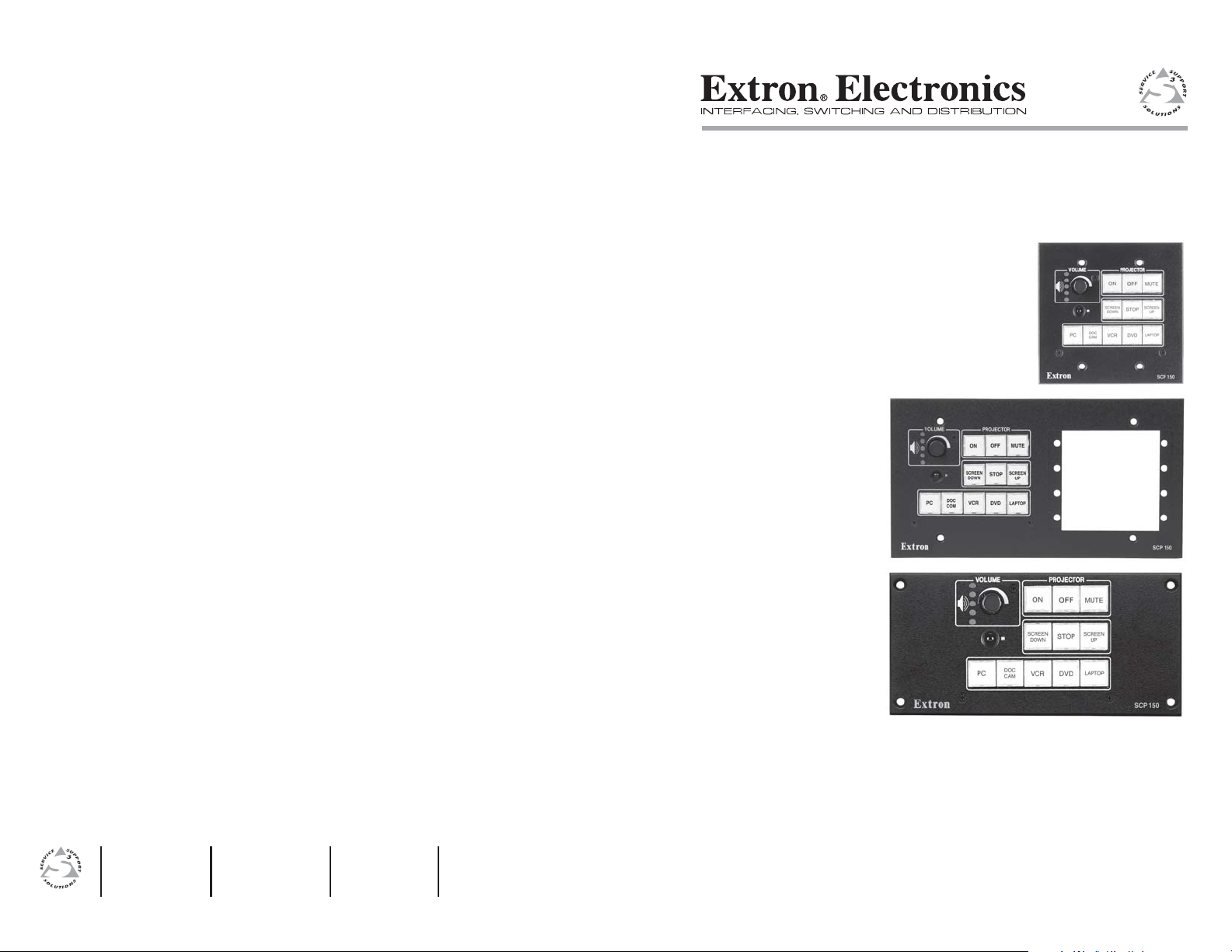
About the SCP 150, SCP 150 AAP, and SCP 150 L
The Extron SCP 150, SCP 150 AAP, and SCP 150 L are hardwired
remote control panels for the Extron System 5 IP switcher. All
models replicate the switcher’s volume, input switching, and
system controls. The SCP 150 AAP also provides four spaces for
the addition of optional architectural adapter plates (AAPs) or
audio, relay, or IR control modules (ACMs, RCMs, IRCMs).
Unless otherwise noted or implied, the term “SCP” refers to all
three models of the SCP 150 (SCP 150, SCP 150 AAP, and
SCP 150 L).
The System 5 IP cannot be configured from the SCP
control panels. All switcher setup must be done from the
switcher or via RS-232. Refer to the System 5 IP
manual for information on setting up the switcher.
The System 5 IP supports up to two SCPs. Up to four control
modules and one IR Link infrared signal repeater can be daisychained with the panels. The SCP accepts signals from the
optional IR 402 remote control.
The panels can be mounted in or on walls or furniture. The
SCP 150 mounts in a 2-gang electrical box, surface mount box,
or mounting bracket and the SCP 150 AAP mounts in a 4-gang
electrical box, surface mount box, or mounting bracket.
The SCP 150 L fits into a compact lectern space, into a wall, or
into an Extron UCM RAAP or UCM 10X8P faceplate.
SCP 150
Chapter Two
Installation and Operation
2
Installation Overview
Features
1-2
SCP 150 • Introduction
Gray, black, white, and RAL9010 white faceplates — The SCPs
are available in four colors for integration into a variety
of environments.
Customizable, illuminated buttons — The panel buttons can be
easily identified, even in low light.
System expandability — The panels can be daisy-chained with
Extron’s control modules (IRCMs, ACMs, RCMs) and an
IR Link to provide versatile remote control options.
Furniture and wall mountability — The SCPs can be mounted
in or on walls or furniture with the use of optional
electrical boxes, surface mount boxes, or mounting
brackets.
Installing or Replacing Button Labels
Mounting Options
UL Requirements
Preparing the Site
Installing the Electrical Box
Cabling the Rear Panel
Pre-installation Testing/Troubleshooting
Mounting the SCP
Front Panel Features
Resetting to Factory Firmware Version
Page 6
Installation and Operation
TEXT
Separate two
piece button here.
Clear Button
Cap
White Backing
Plate
Align tabs and
lock in place.
Use notch to
remove button.
Installation Overview
To install and set up an SCP 150, SCP 150 AAP, or SCP 150L,
follow these steps:
Turn the equipment off. Make sure that the SCP and the
1
System 5 IP switcher are disconnected from the power
source.
Run cables through the wall or furniture where the SCP
2
will be installed.
Prepare the site and install and ground the electrical box,
3
surface mount box, or mounting brackets.
Set the panel address DIP switch on the back of the SCP.
4
Wire the 5-pole captive screw connectors on both ends of
5
the cable that was installed in the wall or furniture in step
.
2
Plug the wired connectors into the CM/IR/SCP
6
connectors on the back of the SCP and on the rear panel of
the switcher.
Restore power to the switcher.
7
Press an input selection button. If the corresponding LED
8
does not light or the switch to the selected input is not
made, disconnect power from the switcher and verify
correct connector wiring at both ends of the cable.
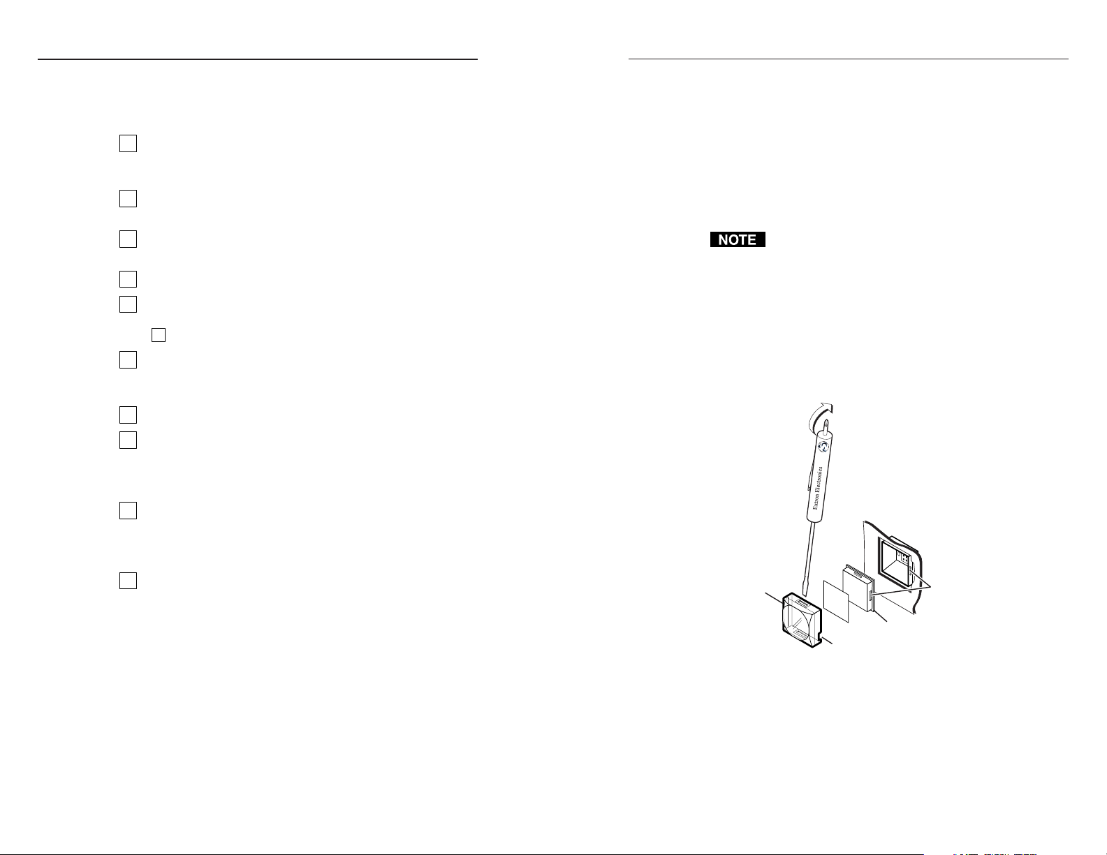
3. Separate the white backing from the clear button cap:
insert the blade of the small screwdriver into the corner
notch and gently twist the blade.
4. Save the translucent, white backing plate, but remove the
text/label insert from the transparent button cap.
5. Select one of the premade button labels from the label
sheets included with the SCP. Remove the label from its
backing and peel the protective film from the front of the
label, if applicable.
You may also use a Brother P-Touch label maker to create
custom labels. Cut the labels so they are square, 1/2 inch
on each side.
6. Insert the button label into the clear button cap, align the
white backing plate with the cap and firmly snap it into
place.
7. Gently but firmly press the reassembled button into place
in the panel.
8. Repeat steps 1 to 7 as needed to relabel other buttons.
Mount the SCP in the electrical box, surface mount box, or
9
mounting brackets. Make sure the faceplate is tied to an
earth ground to prevent damage caused by electrostatic
discharge.
Reconnect the switcher to the A/C power source.
10
Installing or Replacing Button Labels
You may wish to customize the SCP’s button labels. The labels
can be changed at any time, but it is convenient to change them
before you mount the panel. Follow these steps to change the
translucent button labels:
1. Remove the button from the panel: use a small, flat bladed
screwdriver such as an Extron Tweeker to gently pry a
button out from the panel.
2-2 2-3
2. Locate the notch in the corner of one side of the clear outer
SCP 150 • Installation and Operation
layer.
Mounting Options
Mount the SCP 150 or SCP 150 AAP in an electrical box or
surface mount box or use a mounting bracket to secure it to a
wall, podium, table, or other furniture.
Electrical boxes can be attached to wall studs or to furniture.
Use an electrical box deep enough to contain the SCP’s electrical
components and the connected cables.
SCP 150 • Installation and Operation
Page 7
Installation and Operation, cont’d
Flush with
Wall Surface
Screws or Nails
Wall Stud
Wall Box
To mount the SCP 150 in areas of walls or furniture without
studs, use an optional Extron 2-gang mounting bracket, part
#70-086-01, -11, or -21. For the SCP 150 AAP, use an Extron
4-gang mounting bracket, part #70-086-03, -13, or -23.
To mount the SCP 150 externally on a wall or desktop, use an
optional Extron 2-gang SMB surface mount box, part #60-640-02.
For the SCP 150 AAP, use an Extron 4-gang SMB, part
#60-642-02.
UL Requirements
The Underwriters Laboratories (UL) requirements listed below
pertain to the installation of the SCP into a wall or furniture.
1. This unit is not to be connected to a centralized DC power
source or used beyond its rated voltage range.
2. This unit must be installed in a UL listed electrical wall
box.
The UL approved electrical box is not included with the
SCP; the installer is responsible for obtaining and
installing the box.
3. This unit must be installed in accordance with the
National Electrical Code.
Preparing the Site
To mount the panel using either an electrical box or a mounting
bracket, use one of the rough-in templates provided on pages
A-7 through A-9 as a guide to measure and mark the hole in the
wall or furniture through which the SCP will be mounted. The
templates provide measurements for installing the panel with
either an electrical box or a mounting bracket. You do not need
the template if you are mounting the panel using an SMB.
The templates are not to scale and are provided for
reference only.
To prepare the site:
1. Choose a mounting location. If using an electrical box to
wall-mount the panel, locate a stud to which the box will
be attached.
2. Use the appropriate template and panel dimensions in
Appendix A to as a guide to measure and mark the area to
cut out of the wall or furniture.
3. Cut out the opening in the wall or furniture.
Installing the Electrical Box
If you are using a mounting bracket or SMB instead of an
electrical box, follow the mounting instructions that came with
the bracket or SMB.
To install the electrical box:
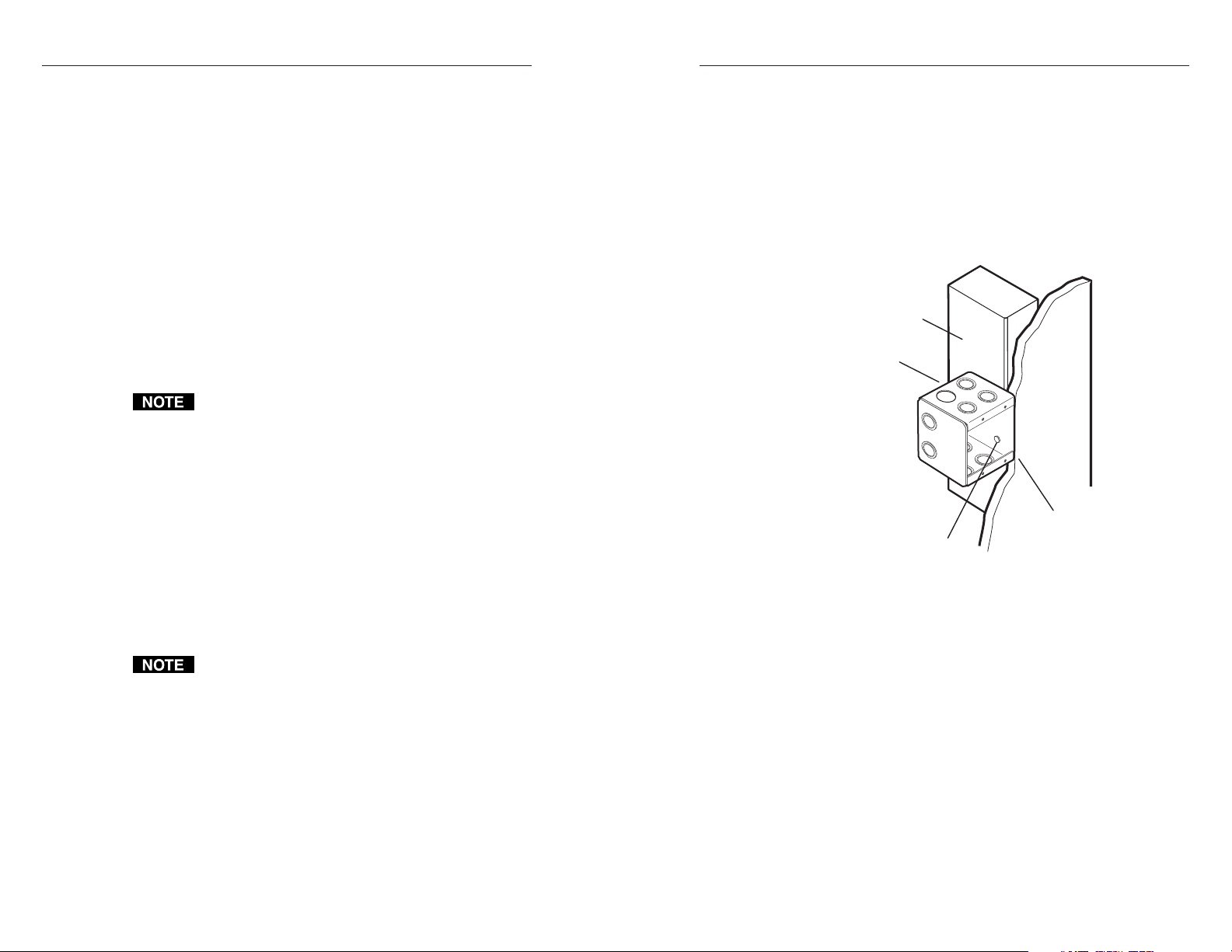
1. Insert the electrical box into the opening, and attach
the wall box to the wall stud (2" x 4") or furniture with
nails or screws, leaving the front edge flush with the
surface, as shown in the following illustration.
To attach the wall box to wood, use four #8 to #10
wood or sheet metal screws. A minimum of 1/2 inch
(1.25 cm) of screw threads must penetrate the wood.
If the wood is a 2 x 4, such as a wall stud, 10-penny or
larger nails can be used.
To attach the electrical wall box to metal, use four #8
or #10 sheet metal screws (self-tapping) or #8 or #10
machine bolts with matching nuts.
2. Feed the cables into the wall box. Cable clamps
should be used to hold the cables in place for strain
relief.
3. Exposed cable shields (braids or foil) are potential
sources of short circuits. Trim back and/or insulate
shields with heat shrink.
SCP 150 • Installation and Operation
SCP 150 • Installation and Operation
2-52-4
Page 8

Installation and Operation, cont’d
Cabling the Rear Panel
Serial/host port — Use this 3-pole captive screw connector to
3
connect to your PC’s RS-232 port. Extron Simple Instruction Set
(SIS) commands can then be issued from the PC to monitor and
obtain information from the SCP. This port is also used for
uploading firmware to the SCP, if necessary. Refer to chapter 3,
Remote Communication, for further details.
Do not connect to this port if the SCP is being used with
2
the System 5IP.
1ON234
1
Panel address DIP switch — If using two SCPs, set DIP
1
J5
3
switch 1 to assign a unique address to each panel. Set the
switch to Off to assign address 00 and On to assign address 01.
Switches 2 and 3 are not used.
The System 5 IP can support up to two SCPs.
The panels must each have a unique address.
DIP switch 4 is used to enable the RS-232/host port of
the SCP 150. Note: If the SCP is connected to the
System 5IP, set switch 4 to the “off” position.
CM/IR/SCP connectors — These two 5-pole captive screw
2
connectors function in exactly the same way and can be used
interchangeably. Connect one connector to a System 5 IP
switcher and the other to a second SCP, an Extron control
module (ACM, RCM, IRCM), or an Extron IR Link infrared
signal repeater.
Two SCPs, up to four control modules, and one IR Link can be
daisy-chained using these connectors. The maximum distance
between the System 5 IP and a connected device is 200' (61 m).
The switcher provides 12 VDC power to the SCP and any daisychained control devices via these connectors, so no additional
power supply is required.
Wire the connectors as shown in the illustration on the next
page. The illustration is a guide; the SCPs, control modules, and
IR Link can be daisy-chained in combinations other than the one
shown.
SCP 150
ADBC E
IR Link
A
+12VDC
Ground ( )
B
IR Link
D
IRCM-DV+
Control Module
ADBC EADBC E
SIGNAL
IR LINK
IR Link
Tx
DVD CONTROL
MENU
TITLE
A
+12VDC
Ground ( )
B
Control signal (IRCM)
C
Modulated IR (IR Link)
D
A
+12VDC
Ground ( )
B
Control signal (IRCM)
C
Modulated IR (IR Link)
D
SCP Communication (IR)
E
1ON234
J5
A
B
C
D
A
B
C
D
E
ENTER
PLAY NEXT PAUSE STOP
REW
Control
Module
VOLUME
IR
INPUT1INPUT2INPUT3INPUT4INPUT
PROJECTORONPROJECTOR
LIGHTS
ON
PROJECTOR
FUNCTION
OFF
BUTTON
LIGHTS
PC
OFF
5
SCP 150
SCP 150
System 5 IP
Rear Port
SCP 150 • Installation and Operation
SCP 150 • Installation and Operation
2-72-6
Page 9

Installation and Operation, cont’d
E
x
t
r
o
n
I
R
V
O
LU
M
E
S
C
P
1
5
0
L
P
R
O
J
E
C
T
O
R
P
R
O
J
E
C
T
O
R
O
N
P
R
O
J
E
C
T
O
R
O
F
F
F
U
N
C
T
I
O
N
B
U
T
T
O
N
L
IG
H
T
S
O
N
L
IG
H
T
S
O
FF
P
C
IN
PU
T
1
IN
PU
T
2
IN
P
U
T
3
IN
P
U
T
4
IN
P
U
T
5
Extron
SCP 150 L
Extron
UCM-RAAP
Pre-installation Testing/Troubleshooting
Before mounting the SCP to the wall or furniture, test the
system to make sure that the connections are correct and the
panel is working correctly. Test the system by powering on the
switcher, then pressing the input selection buttons on the
SCP and watching the LEDs on the switcher to see if the system
switches to the desired inputs.
The connections between the SCP and a System 5 IP
equipped with front panel controls can be tested even if
input/output devices are not available. For a
System 5 IP without front panels controls, input 5 will
be the only input available to view.
Mounting the SCP
Once the system has been cabled and tested, the SCP can be
mounted to the wall or furniture. See Mounting Options, earlier
in this chapter, for a description of the available brackets and
boxes in which the SCP may be mounted.
Mounting in a wall box
1. With power removed, insert the SCP into the wall,
furniture, or SMB.
2. Secure it to the box or mounting bracket with the
provided machine screws. The following illustration shows
an SCP mounted in an electrical box.
If you are not installing the SCP into a grounded metal
electrical box, make sure that the faceplate is grounded to
an earth ground.
Mounting in a rack
The SCP 150 L is rack-mountable using the full rack width
UCM-RAAP mounting plate. Mount the UCM-RAAP using the
rack mounting screws included with the monting plate. Next,
mount the SCP 150 L to the UCM-RAAP using the SCP’s four
mounting screws, as show in the following diagram.
Mounting on a lectern
The SCP 150 L is designed to be mounted on a lectern. To
mount the SCP 150 L, cut a hole of the required size (see
“Preparing the Site” in this chapter) and attach the SCP 150 L
using the provided wood screws.
Lectern
2-8
SCP 150 • Installation and Operation
OR
N
IO
T
C
PROJECT
N
U
N
F
O
T
T
R
U
O
B
T
C
E
J
O
R
P
F
F
O
R
O
T
C
E
J
O
R
P
N
O
VOLUME
C
P
S
T
H
IG
L
F
F
O
S
T
H
IG
L
N
T
O
U
P
N
I
5
T
U
P
N
I
4
T
U
P
N
I
3
T
U
P
150
IN
CP
2
S
T
U
P
IN
1
Extron
SCP 150 L
R
O
T
C
E
N
O
J
I
T
O
C
R
N
N
U
P
F
O
T
T
R
U
O
B
T
C
E
J
O
R
F
P
F
O
R
O
T
C
E
J
O
E
R
P
N
M
O
U
L
PC
O
V
S
HT
LIG
FF
O
S
T
T
LIGH
U
N
SCP 150
O
INP
5
PUT
IN
4
T
INPU
3
T
PU
IN
2
T
U
INP
1
SCP 150 • Installation and Operation
2-9
Page 10

Installation and Operation, cont’d
Front Panel Features
The controls on the SCP 150, SCP 150 AAP, and SCP 150 L
replicate the System 5 IP’s volume, input switching, and system
controls. All the button functions for the System 5 IP and the
SCPs are configured via RS-232 or Ethernet control. See the
System 5 IP user’s manual for instructions on configuring the
buttons.
1
6
2
1
OFF
OFF
INPUT
4
2
FUNCTION
BUTTON
PC
INPUT
5
3
6
PROJECTORONPROJECTOR
2
PROJECTOR
LIGHTSONLIGHTS
INPUT
3
VOLUME
INPUT
IR
INPUT
1
5
VOLUME
5
IR
INPUT1INPUT2INPUT3INPUT4INPUT
PROJECTOR
PROJECTORONPROJECTOR
OFF
LIGHTS
LIGHTS
ON
OFF
FUNCTION
BUTTON
PC
5
3
SCP 150 L
All the buttons on the SCP can light bright green, red,
Extron
4
or amber when selected in stand-alone mode (not
connected to the System 5 IP). Unselected buttons light
dim amber.
SCP 150
6
SCP 150
On and Off buttons — Press these buttons to turn the projector
4
1
on and off. The buttons flash during the projector’s warm up
or cool down cycle, and then light steadily.
and
2
1
2
7
Function buttons — These buttons are fully configurable and
3
can be used to control the System 5 IP’s relays, execute IR or
RS-232 commands, or trigger other buttons. Refer to the
System 5 IP user’s manual for information on configuring these
buttons.
VOLUME
5
IR
INPUT1INPUT2INPUT3INPUT4INPUT
PROJECTOR
PROJECTORONPROJECTOR
OFF
LIGHTS
LIGHTS
ON
OFF
FUNCTION
BUTTON
PC
5
The three function buttons in the middle row (
3
) replicate the
three function buttons on a System 5 IP equipped with front
2
panel controls. The single function button in the top row (
3
an additional function button not found on the switcher.
Input selection buttons — These buttons replicate the five input
4
) is
selection buttons on a System 5 IP equipped with front panel
controls. Press one of these buttons to select an input on the
switcher. Refer to the System 5 IP user’s manual for more
SCP 150 AAP
4
information on input selection.
IR signal pickup sensor — This sensor allows control of the SCP
5
using an optional Extron IR 402 remote control. Point the
remote directly at the sensor. The remote has a range of
SCP 150 AAP
2-10
SCP 150 • Installation and Operation
SCP 150 • Installation and Operation
2-11
Page 11

Installation and Operation, cont’d
approximately 30 feet (9.14 meters) within 40 degrees on either
side of the axis. See the following illustration.
PROJECTORONPROJECTOR
LIGHTSONLIGHTS
IR
INPUT
INPUT
3
2
Extron
30 feet
maximum
PROJECTOR
OFF
OFF
INPUT
4
FUNCTION
BUTTON
PC
INPUT
5
SCP 150 L
IR 402 Remote
VOLUME
INPUT
1
40 40
Resetting to Factory Firmware version
To reset the SCP to the firmware version with which it was
delivered from the factory, press and hold the buttons
numbered 1 and 3 on the front panel while applying power to
the unit. See the following three illustrations.
VOLUME
IR
T
o reset, press these two buttons
simultaneously while applying power
to the SCP 150.
Resetting the SCP 150 to factory defaults
PROJECTOR
SCP 150
2-12
Volume knob and indicator LEDs — Turn this knob to adjust
6
the volume on the input that is currently selected. The five
LEDs indicate the current volume level, as shown in the
following illustration. The top LED is red and the others are
green.
LED Off
LED Blinking
LED On
AAP mounting spaces (SCP 150 AAP only) — Mount up to four
7
VOLUME
0% (Min) or Mute
VOLUME
40-59%
VOLUME VOLUME
1-19%
VOLUME
60-89%
20-39%
VOLUME
90-100% (Max)
single-space AAPs or control modules (IRCMs, ACMs, RCMs)
here.
SCP 150 • Installation and Operation
VOLUME
IR
PROJECTOR
To reset, press these two buttons
simultaneously while applying power
to the SCP 150 AAP.
Resetting the SCP 150 AAP to factory defaults
SCP 150 • Installation and Operation
SCP 150 AAP
2-13
Page 12

Installation and Operation, cont’d
SCP 150
VOLUME
IR
To reset, press these two buttons
simultaneously while applying power
to the SCP 150L.
Resetting the SCP 150 L to factory defaults
PROJECTOR
Extron
Chapter Three
3
Remote Communication
Setting Up RS-232 Communication
2-14
Using Simple Instruction Set (SIS) Commands
Special Function SIS Commands
Using the Switch/Function Button Table
Updating the Firmware
SCP 150 • Installation and Operation
Page 13

Remote Communication
Setting Up RS-232 Communication
The RS-232 interface allows you to obtain information about the
SCP and to activate certain SCP functions from a host computer
or other device (such as a control system) attached to the rear
panel RS-232 port (shown below).
Gnd Rx
Tx
J1
3-pole captive screw connector for the RS-232 port
on the SCP rear panel
Use the following protocol settings for your PC:
Baud rate: 9600
Data bits: 8
Parity: None
Stop Bits: 1
Flow Control: None
The control device (host) can use the Extron Simple Instruction
™
Set
(SIS™) commands.
In order to use the RS-232 port, DIP switch 4 must be
set to the “on” position.
Using Simple Instruction Set (SIS) Commands
SIS commands can be used with the SCP only when it is in
stand-alone mode; that is, DIP switch #4 on the rear panel is in
the ON position. The available commands enable you to test
the front panel LEDs and buttons, and to query for certain
information about the SCP.
You cannot program any SCP buttons or switches using
SIS commands. The SCP’s buttons only reflect what is
programmed for the System 5 IP to which the SCP is
connected.
Host-to-SCP communications
SIS commands consist of one or more characters per field. No
special characters are required to begin or end a command
sequence. When the SCP determines that a command is valid, it
executes the command and sends a response to the host device.
Most responses from the panel to the host end with a carriage
return and a line feed (CR/LF =
the response character string. A string is one or more
characters.
SCP-initiated messages
At power-up, the following SCP-initiated message appears:
© Copyright 2004, Extron Electronics, SCP 150, Vx.xx
This message is displayed only at power-up.
When a local event such as a front panel selection takes place,
the SCP responds by sending a message to the host indicating
what selection was entered (see Switch responses on page 3-5).
No response to these messages is required from the host.
Error responses
When the SCP receives a valid SIS command, it executes the
command and sends a response to the host device. If the SCP is
unable to execute the command because the command is invalid
or contains invalid parameters, the SCP returns an error response
to the host.
Error response codes and their descriptions are shown below.
Each error response is followed by a carriage return.
E10 – Invalid command
E13 – Invalid command parameter
E23 – Bad checksum
E28 – Bad filename/File not found
), which signals the end of
Using the command/response tables
The command/response tables on the following pages list valid
command ASCII codes, the SCP’s responses to the host, and a
description of the command’s function or the results of
executing the command.
The ASCII to HEX conversion table on the next page is for use
with the command/response tables.
SCP 150 • Operation
SCP 150 • Operation
3-33-2
Page 14

Remote Communication, cont’d
ASCII to HEX Conversion Table
•
= current
X1
ASCII to Hex conversion table
Symbol definitions
= CR/LF (carriage return/line feed) (hex 0D 0A)
= Soft carriage return (no line feed)
= Escape key
Esc
= Space
•
X1
= Firmware number
If a command is not case-sensitive, this is indicated by
showing the command letter in uppercase. followed by a
slash (/), then the same letter in lowercase.
Examples: Q/q, I/i
Shows current firmware
version.
firmware version number.
X1
(host to SCP) (host to SCP) (SCP to host) information
x.xx = factory firmware
version number format
y.yyy = updated firmware
version number format
0Q 30 51 x.xx, y.yyy
P2## P1## = SCP address #
•
Command/response table for SIS commands
Command ASCII (Telnet) Hex Response Additional
3-4 3-5
SCP 150 • Remote Communication
Query Firmware version Q/q 51
Query firmware version
Query firmware version—factory and updated
SCP 150 • Remote Communication
Query firmware version—factory 1Q 31 51 x.xx
Query firmware version—updated 2Q 32 51 y.yy
Query part number N/n 4 E 60-495-00
Query firmware and build version +Q 2B 51 x.xx.xxxx
Query model name/description I/i 31 49 SCP150
Request control module and slave 32 I 33 32 49 P1##
information. P2## = SCP address #
Page 15

Remote Communication, cont’d
response.
response, upload the firmware
according to your terminal
emulator’s procedure.
When upload is complete, you
receive the Upl
Special Function SIS Commands
The syntax for setting a special function for an SCP 150 is X? * Y? * __ #,
where X? is the value of the action to be performed, Y? is the value for
the button or switch, and __ is the function number. To view a
function’s setting, use __#, where __ is the function number. In the
following table the values of the X? and Y? variables are different for
each command/function. These values are given in the rightmost
column.
Upload Go When you receive the Go
Esc
(host to SCP) (SCP to host) information
Volume up +V/v VolUp
Volume down -V/v VolDn
Command/response table for SIS commands (continued)
Command ASCII (Telnet) Response Additional
Volume relative function
3-6 3-7
SCP 150 • Remote Communication
Upload firmware
Upload firmware
{Specified number of bytes of data} Upl
zXXX ZapX Sets all button LEDs to amber.
Esc
Reset to factory defaults
Reset to default settings (Zap command)
SCP 150 • Remote Communication
Page 16

Remote Communication, cont’d
values
Y?
and
X?
(host to SCP) (SCP to host) and additional descriptions
is the button:
Y?
is the switch number for the function
X?
or button that was pressed. There are 11
options available (1-11). See the Switch/
X?
is the function switch number or
X?
Function Button Table, later in this chapter,
for these values.
button that was pressed ( 11 options). See
the Switch/Function Button Table for the
functions associated with the switches.
X?
is the LED state:
X?
X?
*
Y?
0 = all LEDs off 0 = no button
* 51# Lmp
Y?
*
X?
1 = green LED on 1 = projector on
2 = red LED on 2 = projector off
3 = green and red 3 = function button 1
LEDs on (Button 4 = function button 2
lights amber.) 5 = function button 3
LED selected:
Y?
values
Y?
and
4 = slow blink green 6 = input button 1
5 = slow blink red 7 = input button 2
6 = slow blink amber 8 = input button 3
7 = fast blink green 9 = input button 4
8 = fast blink red 10 = input button 5
9 = fast blink amber 11 = input button 6
X?
Indicates the LED color of the selected
button.
X?
*
Y?
* 51# Lmp
Y?
(host to SCP) (SCP to host) and additional descriptions
LED blinking
order:
0 = off 0 = no LED
1 = bottom 1 = bottom LED
2 = blink on 2 = LED 2
X? X?
*
Y?
* 52# Vlmp
Y?
*
X?
3 = blink off 3 = LED 3
4 = chase up 4 = LED 4
5 = chase down 5 = LED 5
X?
*
Y?
* 52# Vlmp
Y?
Command/response table for special function SIS commands (continued)
Command/response table for special function SIS commands
Command ASCII Command Response
Switch responses
Button press on front panel or remote (None) SwPrs *
3-8 3-9
SCP 150 • Remote Communication
Button release on front panel (None) SwRls *
Front panel button LED control
FPC lamp control
Command ASCII Command Response
Read FPC lamp
Volume LED control
FPC volume LED control
Read volume LED status
SCP 150 • Remote Communication
Page 17

Remote Communication, cont’d
Using the Switch/Function Button Table
Switches are assigned to specific buttons on the SCP, any
attached remote control module (IRCM/RCM/ACM), or the
IR 402 remote. Each time a button is pressed or released, or a
knob is turned on the SCP or a control module, the switch
number associated with that button appears on your PC
terminal emulator screen (HyperTerminal, etc.) as part of the
host response.
On most of the special function SIS commands, the switch
number is the
(See the Command/response table for special function SIS commands,
earlier in this chapter.)
The following Switch/Function Button table shows which switch
number is associated with each button or knob on the SCP,
control module, or IR 402. In the Switch column, locate the
switch number displayed on your terminal emulator, then look
in the Function Button column beside the number to find out
which button was pressed or released.
value that you enter as part of the command.
X?
The SCP does not use all of the available buttons/
switches.
No buttons can be programmed via the SCP.
Switch number locations
The following illustration shows the button/switch memory
block numbering on the SCP 150 front panel. Refer to the
Switch/Button table, on the previous page. The switch locations
are the same on the SCP 150 AAP and SCP 150 L models.
VOLUME
IR
Switch#9Switch
#10
Switch
#1
Switch
#5
Switch
#11
PROJECTOR
Switch#2Switch
Switch#6Switch
Switch
#12
#8
#7
Switch
#13
SCP 150
Switch Function Button
1 Power on
2 Power off
5 Function 1 (room) button
6 Function 2 (room) button
7 Function 3 (room) button
8 Function 4 (room) button
9 Input 1 selection button
10 Input 2 selection button
11 Input 3 selection button
12 Input 4 selection button
13 Input 5 selection button
Switch/Function Button table
3-10 3-11
SCP 150 • Remote Communication
SCP 150 • Remote Communication
Page 18

Remote Communication, cont’d
Updating Firmware
If necessary, you can replace the SCP’s firmware without
changing firmware chips. This procedure must be performed
using a PC on which the Firmware Loader Software has been
installed. The PC’s RS-232 port must be directly cabled to the
SCP’s RS-232 port.
CAUTION
Do not attempt to upload firmware if a System 5 IP
is connected to the SCP with any connections other
than power. The RS-232 cable from the PC must be
connected
1ON234
J5
directly to the SCP.
System 5 IP
Rear Panel
A
A
+12VDC
Ground ( )
B
B
C
D
E
TxRxG
TxRx
CM/IR/SCP
G+V
CM IR
Power From
System 5 IP
4. Power on the SCP. See the
previous caution.
5. On your PC, start the Firmware
Loader program. The screen on
the right appears:
6. Select the COM port through
which the PC will communicate
with the SCP via RS-232.
7. If the baud rate is not set to 9600,
do the following:
a. Click the Baud button. A baud rate pop-up menu
appears, and the Baud button changes to OK.
ECBDA
SCP
b. From the pop-up menu, select 9600.
8. Click the OK button that was originally the Baud button
(circled in the figure above). The following window opens,
indicating the current firmware version.
SCP 150
Rear Panel
Transmit (Tx)
Receive (Rx)
Ground (Gnd, )
RS-232 to/from Host PC
Each time that the existing firmware is replaced, the SCP
is reset to the factory default settings.
Follow the directions below.
1. Visit the Extron Web site (www.extron.com) to find the
appropriate firmware file for the model of SCP that you
want to update. Save the new firmware file to your PC,
and write down its filename and save location for later use.
2. Connect a cable between the SCP’s RS-232 port and the
serial (RS-232) port of the PC (see chapter 2).
9. Click Upload. You are prompted to select the firmware file
that you downloaded in step 1. Click OK.
10. When the browser window opens, locate and select the
firmware file, then click Open to upload the firmware to
the SCP.
3. Set DIP switch 4 to the ON position.
3-12 3-13
SCP 150 • Remote Communication
SCP 150 • Remote Communication
Page 19

Remote Communication, cont’d
The firmware update file must have a filename extension
of .bin. If the file does not have that extension, it will not
work properly.
11. Follow the instructions on the screen to upload the
firmware.
12. When the firmware uploading is complete, the following
dialog box appears:
SCP 150
Appendix A
A
3-14
Click OK to exit the Firmware Upload program.
SCP 150 • Remote Communication
Specifications, Part Numbers,
Accessories, and Dimensions
Specifications
Included Parts
Accessories
Cables
Panel Dimensions
Templates
Page 20

Specifications, Parts, Accessories, Dimensions
Control/remote — control pad
Serial control port ........................ RS-232, via a 3.5 mm captive screw
connector, 3 pole
Baud rate and protocol ............... 9600 baud, 8 data bits, 1 stop bit, no parity
Serial control pin configurations A = TX, B = RX, C = GND
IR remote control ........................ IR 402 (optional)
30' maximum, 40 degrees off axis
Program control .......................... Extron’s Simple Instruction Set (SIS
™
)
General
Power ............................................ 12 VDC, at 0.5 A, from the System 5 IP
switcher
Temperature/humidity .............. Storage: -40 to +158 °F (-40 to +70 °C) /
10% to 90%, noncondensing
Operating: +32 to +122 °F (0 to +50 °C) /
10% to 90%, noncondensing
Rack mount .................................. No, but furniture/wall mountable with
included faceplates and electrical boxes or
optional mounting bracket kits or AAP wall
plates.
Enclosure type .............................. Metal
Enclosure dimensions
SCP 150 faceplate ............. 4.5" H x 4.6" W x 0.1" D (2 gang)
11.4 cm H x 11.7 cm W x 0.3 cm D
SCP 150 AAP faceplate .... 4.5" H x 8.25" W x 0.1"D (4 gang)
11.4 cm H x 11.7 cm W x 0.3 cm D
SCP 150 L faceplate .......... 3.2" H x 6.5" W x 0.1"D
8.0 cm H x 16.5 cm W x 0.3 cm D
Circuit board (all models) 2.9" H x 3.5" W x 0.5" D
7.4 cm H x 8.9 cm W x 1.3 cm D
[Allow at least 1.5" (3.8 cm) depth in the
wall or furniture. Depth excludes
connectors, knob, and buttons.]
Product weight............................. 0.3 lbs (0.1 kg)
Shipping weight ........................... 2 lbs (1 kg)
Vibration ....................................... ISTA 1A in carton (International Safe
Transit Association)
Listings .......................................... UL, CUL as a component of the System 5 IP
Compliances ................................. CE as a component of the System 5 IP
MTBF ............................................. 30,000 hours
Warranty ....................................... 3 years parts and labor
All nominal levels are at ±10%.
Specifications are subject to change without notice.
Included Parts
These items are included in each order for an SCP 150,
SCP 150 AAP, or SCP 150 L:
Included parts part number
SCP 150 (controller only - no faceplate) 60-495-00
or
SCP 150 (gray, black, white, RAL9010) 60-495-01, -02, -03, -05
or
SCP 150 AAP (gray, black, white, RAL9010)
or
SCP 150 L (black, white, RAL 9010) 60-495-32, -33, -35
3.5 mm, 5-pole captive screw connector (2) 10-319-01
3.5 mm, 3-pole captive screw connector (1) 10-265-03
Button labels (text) 33-954-01
Button labels (symbols) 33-955-01
International faceplate labels
(gray, black, white) 33-953-01, -02, -03
Tweeker (small screwdriver)
SCP 150 User’s Manual
Replacement
60-496-01, -02, -03, -05
SCP 150 • Specifications, Parts, Accessories, Dimensions
SCP 150 • Specifications, Parts, Accessories, Dimensions
A-3A-2
Page 21

Specifications, Parts, Accessories, Dimensions, cont’d
Accessories
These items may be ordered separately:
Accessories Part number
2-gang mounting bracket (gray, black, white, RAL9010)
4-gang mounting bracket
2-gang SMB surface mount box 60-640-02
4-gang SMB surface mount box 60-642-02
Button labels (international text) 33-956-01
IR 402 remote control 70-207-01
Cables
These cables may be ordered separately:
Comm-Link cable Part number
50 feet/15.2 meters long 26-461-01
100 feet/30.5 meters long 26-461-02
200 feet/61 meters long 26-461-03
400 feet/122 meters long 26-461-04
Bulk 500 feet/152.4 meters long 22-119-02
Bulk 1000 feet/304.8 meters long 22-119-03
70-086-01, -11, -21, -25
(gray, black, white, RAL 9010)
70-086-03, -13, -23, -25
Panel Dimensions
R.070 TOP
EDGE ALL
AROUND
5X Ø.125 THRU
wØ.180 X 90°
FAR SIDE
Ø.219 THRU
wØ.392 X 82°
NEAR SIDE
(.10 THK)
5X Ø.125 THRU
wØ.180 X 90°
FAR SIDE
R. 070 TOP
EDGE ALL
AROUND.
Ø.219 THRU
wØ.392 x 82°
NEAR SIDE
(.10 THK.)
Ø.520 THRU
4.500
2X 3.858
3.505
3.390
3.305
3.195
2X 3.105
2.905
2.705
2.375
2.330
1.563
2X 1.000
2X .576
.000
SCP 150
SCP 150 AAP
.000
2X 3.858
2X 3.105
2X 1.000
2X .576
Ø.520 THRU
4.500
3.505
3.390
3.305
2.905
2.705
2.375
2.330
1.563
.000
5X .903
.675
4X Ø.160 THRU
wØ.290 X 82°
(CODED "E")
5X .905
1.320
.000
.675
1.300
2X 1.394
SEE DETAIL "A"
1.320
1.300
2X 1.405
2X 2.980
1.805
2.360
SEE DETAIL "B"
2X 2.980
1.805
3.195
SEE DETAIL "B"
3X Ø.120 THRU
wØ.220 X 82°
(CODED 'F')
4X R.25
2.360
3.925
3X Ø.120 THRU
wØ.220 x 82°
(CODED 'F')
2X 3.206
3.925
4X Ø.160 THRU
6.200
w Ø.290 X 82°
(CODED E)
4.600
SEE DETAIL "C"
2.200
4X R.25
8.250
2X 6.845
1.880
.940
.640
.320
A-4 A-5
SCP 150 • Specifications, Parts, Accessories, DimensionsSCP 150 • Specifications, Parts, Accessories, Dimensions
DETAIL `A'
3.520
+.010-.000
2.740
1.370
1.375
2.750
3.000
DETAIL `C'
3.110
1.555
DETAIL `B'
1.760
8X Ø.170 THRU
4x R.050
.700
.350
1.500
.320
.640
1.405
1.050
2.100
2.810
+0.015-0.000
Page 22

Specifications, Parts, Accessories, Dimensions, cont’d
SCP 150 L
.120
.220 X 82°
Ø
Ø
W
3X
MARKED F
2.755
Templates
The templates are not to scale and are provided for
reference only.
.156
.290 X 82°
Ø
Ø
W
4X
MARKED E
6.500
2X 6.250
E
E
3.6"
(9.15 cm
)
F
4.875
2.8"
(7.1 cm)
SURFACE CUT-OUT AREA
FOR FURNITURE MOUNT
F
2.250
Top Panel
Electrical Box
Location of SCP 150
A-6
3.150
E
2.770
2X 2.855
1.710
.392 X 82°
.219
Ø
Ø
W
2X .380
2X .295
To install SCP 150
1.625
F
SCP 150
TEMPLATE IS NOT FULL SIZE.
directly into furniture,
cut along this line.
Cut-Out Template for Extron's SCP 150
E
.000
2X .250
.000
0.100
SCP 150 • Specifications, Parts, Accessories, DimensionsSCP 150 • Specifications, Parts, Accessories, Dimensions A-7
Page 23

Specifications, Parts, Accessories, Dimensions, cont’d
To install SCP 150
directly into furniture,
7.2"
8.3 cm)
(1
cut along this line.
SCP 150 AAP
FOR FURNITURE MOUNT
SURFACE CUT-OUT AREA
TEMPLATE IS NOT FULL SIZE.
6.5"
(16.5 cm)
3.15"
(8.0cm)
2.85"
(7.2 cm)
SURFACE CUT-OUT AREA
FOR FURNITURE MOUNT
3.6"
(9.15 cm)
Top Panel
Location of SCP 150
A-8
Top Panel
Cut-Out Template for Extron's SCP 150 AAP
Electrical Box
2.8"
(7.1 cm)
To install SCP 150
directly into furniture,
cut along this line.
SCP 150 L
TEMPLATE IS NOT FULL SIZE.
Cut-Out Template for Extron's SCM-150L
SCP 150 • Specifications, Parts, Accessories, DimensionsSCP 150 • Specifications, Parts, Accessories, Dimensions
A-9
 Loading...