

Page 1

User’s Manual
SCP 100 Control Pad
System 5
crcr
cr Accessories
crcr
68-390-01
Printed in the USA
Page 2

Installation
System 5
cr
• SCP 100 User’s Manual • Extron
Page 3

Installation
Chapter One - Installation
System 5cr Options: SCP 100....................................................................... 1-1
Installing the SCP 100 (60-270-01, 02 & 03) ..................................... 1-1
Electrical Wall Boxes .......................................................................... 1-2
Making Cables.................................................................................... 1-3
Testing the SCP 100........................................................................... 1-4
Chapter T wo - SCP 100 Operation and Reference
SCP 100 Operation ...................................................................................... 2-1
Room Button and LED........................................................................ 2-1
Display Controls ................................................................................. 2-2
Audio Controls and Indicators ............................................................ 2-2
Five Input Select Buttons.................................................................... 2-2
Extron’s Comm-Link Cable................................................................. 2-3
Part Numbers ..................................................................................... 2-3
Engineering Drawing (not to scale) .................................................... 2-4
Cutout Template (drawn to scale) ....................................................... 2-5
Index for System 5 manual ................................................................. 2-7
The following icons may be used in this manual:
___ Important information – for example, an action or a step that must
be done before proceeding.
___ A Warning – possible dangerous voltage present.
___ A Warning – possible damage could occur.
__ A Note, a Hint, or a Tip that may be helpful.
Other reference material
System 5 Switching system – System 5 manual (68-388-01)
Index – System 5 manual (68-388-01)
Glossary of terms – System 5 manual (68-388-01)
IR Broadcaster manual (68-392-01)
Power Sensor manual (68-391-01)
IR 40 Instruction card (68-405-01)
SCP 100 User’s Manual
(used with System 5cr Switcher)
68-390-01, Rev. A, 99-02
Extron • System 5cr • SCP 100 User’s Manual
Page 4

Installation
Notes
System 5
cr
• SCP 100 User’s Manual • Extron
Page 5

System 5cr SCP 100 Control Panel
User’s Manual
Chapter One
Introduction and Features
SCP 100 Installation
Installing Electrical Boxes
Making Cables
Specifications
1
Page 6
Installation
System 5
__ For simplicity, the System 5
__ Setup, or “Config” cannot be done from an SCP 100.
crcr
cr Accessories: SCP 100
crcr
cr
is often referred to as System 5.
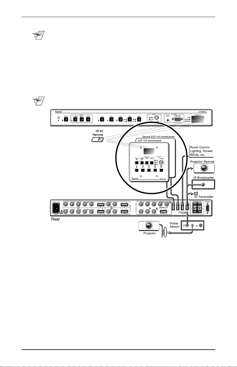
There can be one or two optional SCP 100 remote panels
installed on a System 5. All of the System 5 front panel normal
operation functions can be controlled from an SCP 100, except for
the Setup (Config) procedures.
Signals received by the SCP 100’s IR port are transferred by
hard-wired cable to the System 5. For details on front panel
operations, see the System 5 User’s Manual (68-388-01).
Figure 1-1. System 5 Options and Accessories
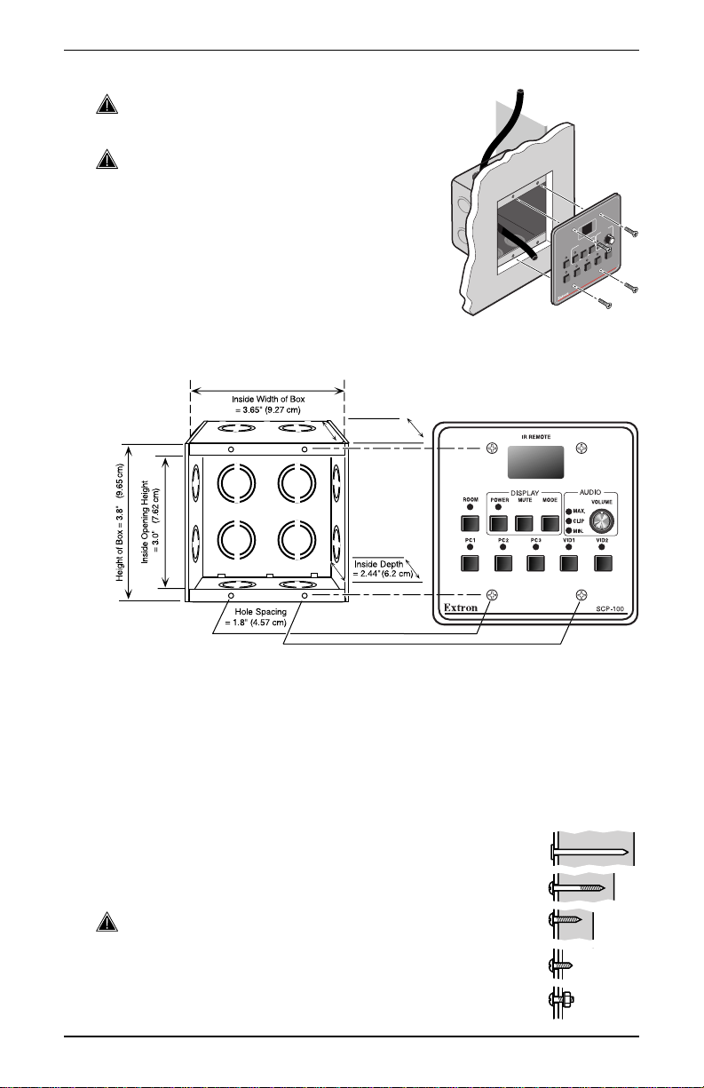
The SCP 100 can be mounted in a wall, podium, table, etc., using
a standard, 2-gang electrical box, as illustrated in Figure 1-2. How
and where it mounted is the decision of the system designer.
Each SCP 100 is connected to the System 5 by a cable, using
3.5 mm, 5-pole captive screw connectors. The connectors are
provided with each unit, however, because cable length
requirements vary, cables are the responsibility of the installer.
Installing the SCP 100 (60-270-01, 02 & 03)
The SCP 100 is designed to be used with standard electrical wall
boxes, such as those used for light switches. Figure 1-2 shows
how it can be installed in a wall, desk, podium, etc. The
procedures provided here assume that the electrical wall boxes
have been installed and the cable(s) have been run for the
interface system.
1-1
System 5
cr
• SCP 100 User’s Manual • Extron
Page 7
Electrical Wall Boxes
___ When installing the SCP 100, adhere to all
country, state and local electrical codes.
___ Extron provides an electrical box with
each SCP 100. However, you may
choose a different box. Because of the
loose tolerances for electrical boxes, it
is recommended that you measure the
exact box that you plan to use before
making any precise cuts. Also refer to
the box dimensions (2.5” deep), and
not the SCP 100 dimensions.
Figure 1-2. The SCP 100 mounts in a standard electrical wall box.
Page 2-5 has a template that may be used for cutting a hole to
accommodate an SCP 100 and the electrical box.
Outside Depth
= 2.5 " (6.35 cm)
Installation
O
I
D
U
A
VOLUMN
MIN.
Y
A
MODE
L
P
UNITY
S
I
2
D
D
I
MUTE
V
MAX.
1
POWER
D
I
V
ROOM
PRESET
3
C
P
2
C
P
0
0
1
1
-
C
P
P
C
S
Figure 1-3. A standard electrical wall box dimensions
Use screws, bolts or nails to install the electrical box, depending
upon the type and thickness of the material to which the box is
being attached. See examples in Figure 1-4.
• For wood, use four #8 to #10 wood or sheet metal screws. A
minimum of 1/2 inch (1.25 cm) of screw threads must penetrate
the wood. If the wood material is a 2x4, such as a
wall stud, 10-penny or larger nails may be used.
• For attaching the electrical box to metal, use four
#8 to #10 sheet metal screws (self-tapping) or #8
to #10 machine bolts with matching nuts.
___ The electrical box must be deep enough to
accommodate the electronics within the SCP 100
unit, as well as the cable.
Figure 1-4. Use screws, nails or bolts to attach the electrical box.
Extron • System 5cr • SCP 100 User’s Manual
1-2
Page 8
Installation
Making Cables
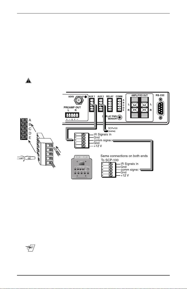
Extron provides the 3.5 mm captive screw connectors with the
SCP-100, however a cable will have to be made to fit your
installation requirements. Wire the cable to be used between the
System 5 connector marked Aux1 or Aux2 (rear panel) and the
SCP 100 for a one-to-one configuration (wire pin #1 of one
connector to pin #1 of the other, #2 to #2, etc.) The contact
assignments are shown in Figure 1-5. Both ends of the cable use
a 3.5 mm, captive screw connector. No soldering is required for
this connector, simply insert the wires as shown in Figure 3 and
tighten the screws.
___ The maximum cable length for an SCP 100 to System 5 application
is 300 feet (91.4 meters).
Figure 1-5. Contact assignments for SCP 100 to System 5 connections
Testing the SCP 100
When finished, either end of the cable can plug to either device.
However, because there will be +12 volts from the System 5, it is
best to plug the cable to the SCP 100 first, and then to the
System 5. There is no setup procedure for this device. Proceed
with the operation of the panel(s) to verify that it is working
properly.
__ The IR 40 remote can be used from a distance of up to 100 feet
(30.5 meters) from the SCP 100 IR port.
1-3
System 5
cr
• SCP 100 User’s Manual • Extron
Page 9

System 5cr SCP 100 Control Panel
User’s Manual
Chapter T wo
Operation
SCP 100 Panel Buttons
Engineering Drawings
Index for System 5
2
cr
Page 10

Operation
SCP 100 Operation
The SCP 100 panel replicates the normal operations of the front
panel. The function names are the same. As stated earlier, Setup
(or Config) Mode operations cannot be done from the SCP 100.
The IR Remote port receives IR 40 signals and sends them to the
System 5 by the cable. Signals from other IR devices are blocked
at the System 5.
Any “learned” IR commands that are stored in the System 5
memory will be transmitted from the System 5’s IR emitter or the
optional IR Broadcaster when the associated button is pressed on
the SCP 100 panel, just as it will when that same front panel
button is pressed.
Figure 2-1. SCP 100 panel controls are similar to those on the front panel.
Room Button and LED
This button and LED work with the relay contact connections
provided on the rear panel of the System 5. The button can
activate/deactivate a room condition, such as turn lights on/off and
raise/lower a viewing screen. The LED indicates when the
condition exists. Exactly how the feature is used depends upon
the user-defined application and what is connected to the “Relay”
connector on the rear panel.
2-1
System 5
cr
• SCP 100 User’s Manual • Extron
Page 11

The Room button can operate in one of two ways: latching (press
on, press off) or momentary (press on, release off). This
programming can only be done through Windows® Control
Program (RS-232).
_ For example, pressing the Room button once could lower a screen
and turn room lights off and the LED will remain lit. Press the
button again to turn the room lights on, raise the viewing screen
and the LED goes out.
Display Controls
___ These buttons only function after being programmed. (See Setup
Mode Procedures in the System 5 manual or product label.)
Power – After this button has been setup to learn the power on and
off from the projector’s IR remote control, it will power the display
device on or off. There is a power up and power down delay for
many projectors. The Display Power LED will blink fast during
projector power up and will blink slowly during projector power
down. The blinking time is generated within the System 5, and
its duration can be programmed through RS-232. The blink
duration does not come from the projector.
Mute – This button functions as the display’s Mute on/Mute off
switch, after it has learned the video mute signal from the
projector’s IR remote.
Mode – Effective on display devices that do not automatically
detect the type of video signal, this button changes the mode of
the display device between computer-video, composite video
and S-Video. This also takes the place of the single-button
(step) mode function found on some projector remote controls.
Audio Controls and Indicators
The Audio Volume Control knob and LEDs for the amplified output.
Max LED – lights when the audio output level control has reached
its maximum point. This does not indicate the audio level.
Clip LED – lights when the output level is beginning to overdrive
(peak). This indicator is used to set the audio attenuation for the
inputs. Clip level is when this LED blinks occasionally.
Min LED – lights when the audio output level control has reached
its minimum point. This does not indicate the audio level.
_ When all audio inputs have been set up to the same level coming
into the System 5, the Volume knob functions as the master volume
control for the amplified output. (See Setup Mode Procedures.)
Operation
Five Input Select Buttons
PC1 – select button for PC Video and Audio. This selects the input
from the VGA/Audio connectors on the System 5 front panel.
PC2 and PC3 – select buttons for an RGBS or RGBHV source (and
audio) from the PC2 or PC3 sections of the rear panel. This could
be from a computer or through a computer-video interface.
VID1 and VID2 – select buttons for the two Composite Video or
S-Video inputs sources (VCR, DVD, etc.)
Extron • System 5cr • SCP 100 User’s Manual
2-2
Page 12

Reference
Extron’s Comm-Link cable
Comm-Link cable was designed for installations such as the
System 5. You may choose to use this or a similar low-loss cable.
Pin assignments and suggested Wire usage is as follows:
A = Signal without carrier (violet or blue) = 22 AWG
B = Ground (black) = 18 AWG
C = Signal with carrier (white) = 22 AWG
D = Ground (Drain) = 24 AWG
E = +12V (red) = 18 AWG
Figure 2-2. Extron’s Comm-Link cable was designed for use with the SCP 100.
Part Numbers
Comm-Link Cable:Cut lengths Part #
50 feet 26-461-01
100 feet 26-461-02
200 feet 26-461-03
400 feet 26-461-04
Bulk spools:
500 feet 22-119-02
1,000 feet22-119-03
SCP 100 Panels:
Gray 60-239-01
Black 60-239-02
White 60-239-03
Captive Screw Connector:
(included with each SCP 100)
2-3
5-pole, 3.5 mm 10-319-10
System 5cr • SCP 100 User’s Manual • Extron
Page 13

Engineering Drawing (not to scale)
This drawing may be used to show dimensions and parts of the
SCP-100 panel.
Reference
Figure 2-3. Not-to-Scale engineering drawing
Extron • System 5cr • SCP 100 User’s Manual
2-4
Page 14

Reference
Cutout Template (drawn to scale)
This drawing may be used as a template for cutting a hole to
accommodate a 2-gang electrical box. However, because of the
loose tolerances for electrical box dimensions, it is recommended
that you measure the exact box that you plan to use before
making any critical cuts.
Figure 2-4. Scale drawing for cutting hole.
2-5
System 5cr • SCP 100 User’s Manual • Extron
 Loading...