

Extron electronics SB 33 A Series, SB 33 A 46-55, SB 33 A 55-65, SB 33 A 65-70, SB 33 A 75-80 User Manual
Page 1
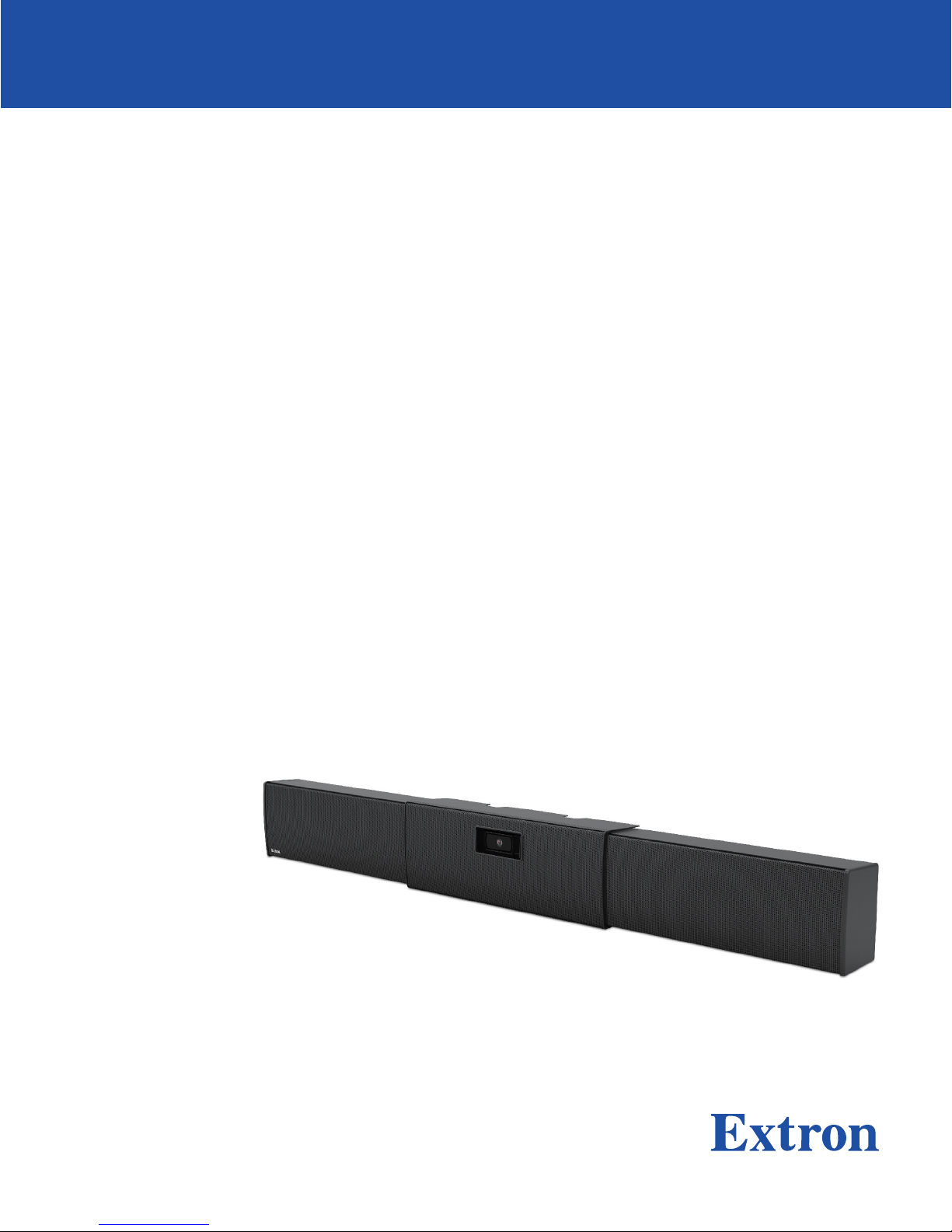
SB 33 A Series
Adjustable Width Sound Bar
User Guide
Speakers
TBD
68-3103-01 Rev. A
05 19
Page 2
Safety Instructions
Safety Instructions • English
WARNING: This symbol, , when used on the product, is intended to
alert the user of the presence of uninsulated dangerous voltage within the
product’s enclosure that may present a risk of electric shock.
ATTENTION: This symbol, , when used on the product, is intended
to alert the user of important operating and maintenance (servicing)
instructions in the literature provided with the equipment.
For information on safety guidelines, regulatory compliances, EMI/EMF
compatibility, accessibility, and related topics, see the Extron Safety and
Regulatory Compliance Guide, part number 68-290-01, on the Extron
website, www.extron.com.
Sicherheitsanweisungen • Deutsch
WARNUNG: Dieses Symbol auf dem Produkt soll den Benutzer darauf
aufmerksam machen, dass im Inneren des Gehäuses dieses Produktes
gefährliche Spannungen herrschen, die nicht isoliert sind und die einen
elektrischen Schlag verursachen können.
VORSICHT: Dieses Symbol auf dem Produkt soll dem Benutzer in
der im Lieferumfang enthaltenen Dokumentation besonders wichtige
Hinweise zur Bedienung und Wartung (Instandhaltung) geben.
Weitere Informationen über die Sicherheitsrichtlinien, Produkthandhabung,
EMI/EMF-Kompatibilität, Zugänglichkeit und verwandte Themen finden Sie in
den Extron-Richtlinien für Sicherheit und Handhabung (Artikelnummer
68-290-01) auf der Extron-Website, www.extron.com.
Istruzioni di sicurezza • Italiano
AVVERTENZA: Il simbolo, , se usato sul prodotto, serve ad
avvertire l’utente della presenza di tensione non isolata pericolosa
all’interno del contenitore del prodotto che può costituire un rischio di
scosse elettriche.
ATTENTZIONE: Il simbolo, , se usato sul prodotto, serve ad avvertire
l’utente della presenza di importanti istruzioni di funzionamento e
manutenzione nella documentazione fornita con l’apparecchio.
Per informazioni su parametri di sicurezza, conformità alle normative,
compatibilità EMI/EMF, accessibilità e argomenti simili, fare riferimento
alla Guida alla conformità normativa e di sicurezza di Extron, cod. articolo
68-290-01, sul sito web di Extron, www.extron.com.
I
Instrucciones de seguridad • Español
ADVERTENCIA: Este símbolo, , cuando se utiliza en el producto,
avisa al usuario de la presencia de voltaje peligroso sin aislar dentro del
producto, lo que puede representar un riesgo de descarga eléctrica.
ATENCIÓN: Este símbolo, , cuando se utiliza en el producto, avisa
al usuario de la presencia de importantes instrucciones de uso y
mantenimiento recogidas en la documentación proporcionada con el
equipo.
Para obtener información sobre directrices de seguridad, cumplimiento
de normativas, compatibilidad electromagnética, accesibilidad y temas
relacionados, consulte la Guía de cumplimiento de normativas y seguridad
de Extron, referencia 68-290-01, en el sitio Web de Extron, www.extron.com.
Instructions de sécurité • Français
AVERTISSEMENT : Ce pictogramme, , lorsqu’il est utilisé sur le
produit, signale à l’utilisateur la présence à l’intérieur du boîtier du
produit d’une tension électrique dangereuse susceptible de provoquer
un choc électrique.
ATTENTION : Ce pictogramme, , lorsqu’il est utilisé sur le produit,
signale à l’utilisateur des instructions d’utilisation ou de maintenance
importantes qui se trouvent dans la documentation fournie avec le
matériel.
Pour en savoir plus sur les règles de sécurité, la conformité à la
réglementation, la compatibilité EMI/EMF, l’accessibilité, et autres sujets
connexes, lisez les informations de sécurité et de conformité Extron, réf.
68-290-01, sur le site Extron, www.extron.com.
Page 3
Copyright
© 2019 Extron Electronics. All rights reserved. www.extron.com
Trademarks
All trademarks mentioned in this guide are the properties of their respective owners.
The following registered trademarks (®), registered service marks (SM), and trademarks (TM) are the property of RGBSystems, Inc. or
ExtronElectronics (see the current list of trademarks on the Terms of Use page at www.extron.com):
Extron, Cable Cubby, ControlScript, CrossPoint, DTP, eBUS, EDID Manager, EDID Minder, Flat Field, FlexOS, Glitch Free. Global
Configurator, GlobalScripter, GlobalViewer, Hideaway, HyperLane, IPIntercom, IPLink, KeyMinder, LinkLicense, LockIt, MediaLink,
MediaPort, NetPA, PlenumVault, PoleVault, PowerCage, PURE3, Quantum, Show Me, SoundField, SpeedMount, SpeedSwitch,
StudioStation, SystemINTEGRATOR, TeamWork, TouchLink, V-Lock, VideoLounge, VN-Matrix, VoiceLift, WallVault, WindoWall, XTP,
XTPSystems, and ZipClip
Registered Service Mark
(SM)
: S3 Service Support Solutions
Registered Trademarks (
Trademarks (™
)
®
)
Page 4

Contents
Introduction ...............................................1
About this Guide .................................................. 1
Features .............................................................. 2
Application Example ............................................ 3
Installation ................................................. 4
Mounting Instructions .......................................... 4
Installing the Wallplate on a Non-masonry
Wall ................................................................ 5
Installing the Wallplate on a Masonry Wall ........ 7
Attaching the SB 33 A to the Wallplate ............ 9
Mounting a Camera ....................................... 11
SMK V SB 33 VESA Mounting Kit ...................... 20
Installation ..................................................... 20
Aligning the SB 33 Speaker to the Display ..... 26
Operation ................................................. 27
SB 33 A Internal Amplifier Front Panel (inside
right speaker module) ....................................... 27
Internal Adjustments .......................................... 31
Setting Bass and Treble ................................. 31
Reference Information ............................. 32
Defeating the Auto Power-down Timer .............. 32
Troubleshooting ................................................. 35
Amplifier Fails to Exit Standby Mode
Promptly ....................................................... 35
Amplifier Enters Standby Mode Too Early ....... 35
SB 33 A Series User Guide • Contents vii
Page 5

SB 33 A Series User Guide • Contents viii
Page 6
Introduction
This section gives an overview of the Extron SB 33 A Series Sound Bar Speaker. Topics
include:
• About this Guide
• Overview
• Features
• Application Examples
About this Guide
This guide describes the installation and set up of the SB 33 A Series Speaker.
NOTE: Observe all applicable building codes and local ordinances when installing the
SB 33 A speaker.
In this guide, the terms “speaker” and “sound bar” are used interchangeably to refer to the
SB 33 A Series Sound Bar Speaker.
Product Description
The SB 33 A is an adjustable-width sound bar speaker for use in small-to-medium
conference rooms. It will feature two 3" full range speaker speaker drivers, driven by an
internal amplifier module. The SB 33 A speaker accepts balanced and unbalanced stereo
input signals on three individually buffered inputs.
The SB 33 A is configurable for use with an internal webcam using the built-in adjustable
shelf and window with a built-in door. It can also be configured to mount a PTZ camera with
optional shelf, or configured for no camera with the optional blank center grille. The SB 33 A
sound bar enclosure is adjustable to match the width of the display and is mounted under
the display. The SB 33 A will be offered in four different sizes to accommodate screen sizes
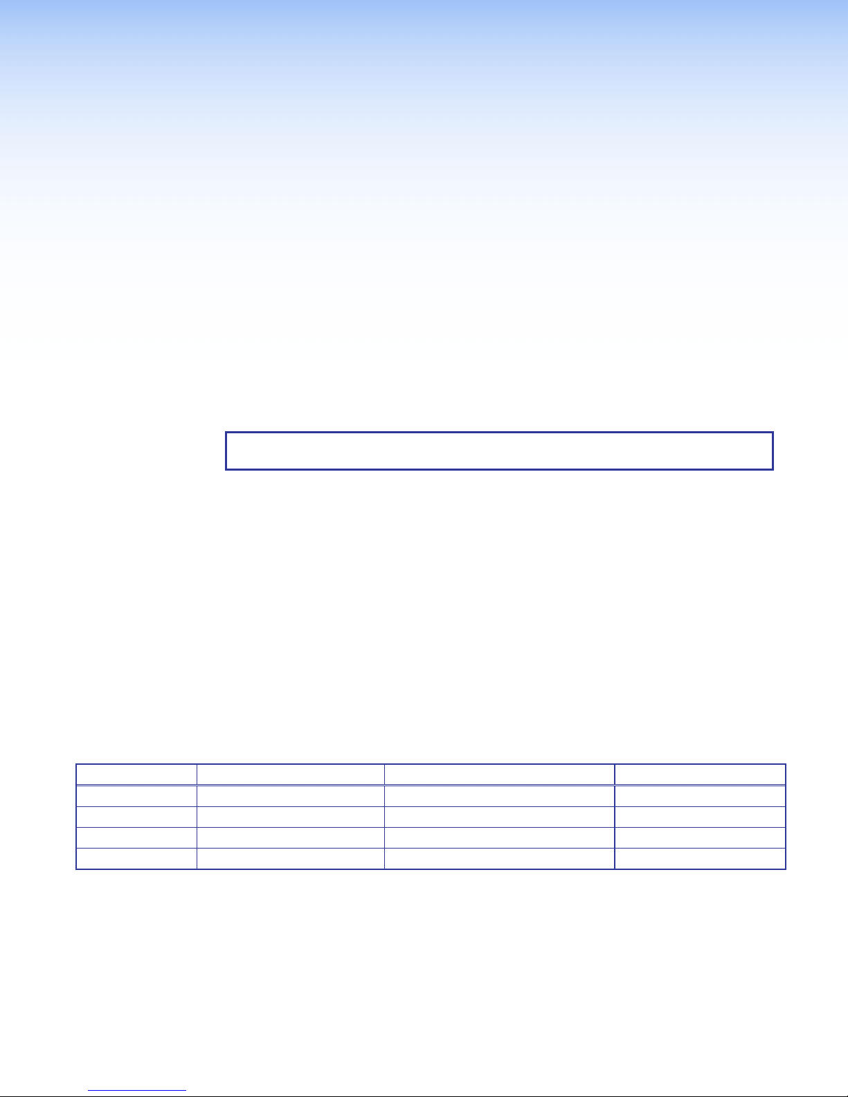
from 46" to 80", as shown in the table below.
Option Fit Display Size (diagonal) Fit Display Width Speaker Module Width
SB 33 A 46-55 46" — 55" 40" — 49" (101.6 cm — 124.5 cm) 16.25" (41.3 cm)
SB 33 A 55-65 55" — 65" 48" — 57" (121.9 cm — 144.8 cm) 20.25" (51.4 cm)
SB 33 A 65-70 65" — 70" 56" — 65" (142.2 cm — 165.1 cm) 24.25" (61.6 cm)
SB 33 A 75-80 75" — 80" 64" — 73" (162.6 cm — 185.4 cm) 28.25" (71.8 cm)
Figure 1. SB 33 A Series Table
SB 33 A Series User Guide • Introduction 1
Page 7
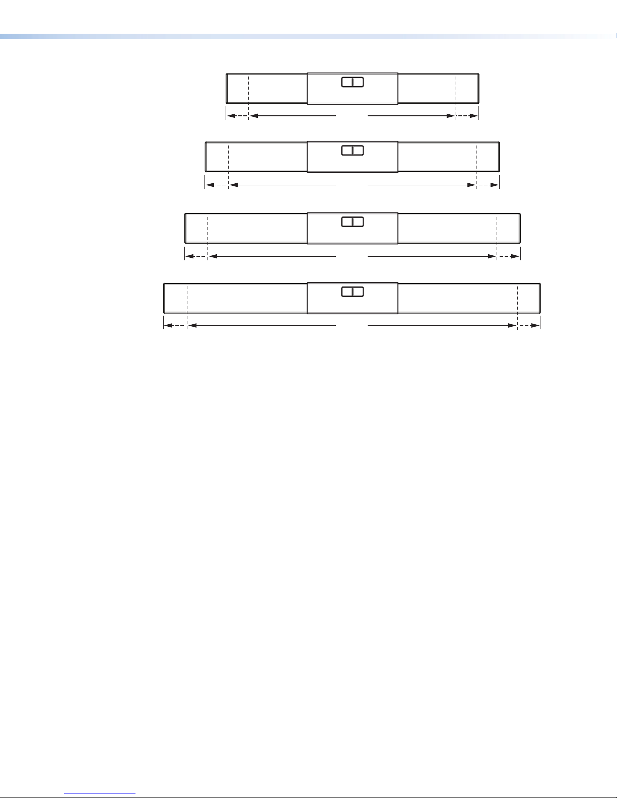
40"- 49"
SB 33 A 75-80
SB 33 A 46-55
48"- 57"
SB 33 A 55-65
56"- 65"
SB 33 A 65-70
64"- 73"
Figure 2. SB 33 A Series Model Options
The SB 33 A supports mounting directly to the wall under the display using the included
wallplate. It can also be attached to an articulating display mount using the optional VESA
mounting kit.
Features
• Provides enhanced audio quality for collaboration spaces
• Adjustable width to match the display — Perfectly matches the width of any display
from 46” to 80”
• Configurable for an internal webcam, a PTZ camera, or no camera — Suitable
for self-contained huddle spaces or video conference rooms
• 3” (76 mm) full-range drivers with a tuned port for bass extension — Optimized
for collaboration applications
• Frequency range: 100 Hz to 20 kHz
• Internal Extron ENERGY STAR qualified Class D amplifier — High performance
stereo amplifier with CDRS, automatic clip limiter, and auto power-down with fast
power-up
• Compatible with VCM series volume and mute controllers — Can be used
without a control system
• Compatible with select MLC controllers that include VCM volume and mute
ports
• Internal level, bass, and treble adjustments — Once set, these controls are hidden
and protected from tampering
• Optional VESA mounting kit
• ADA compliant when used with the included wall bracket — Protrudes less than
four inches from the wall
SB 33 A Series User Guide • Introduction 2
Page 8
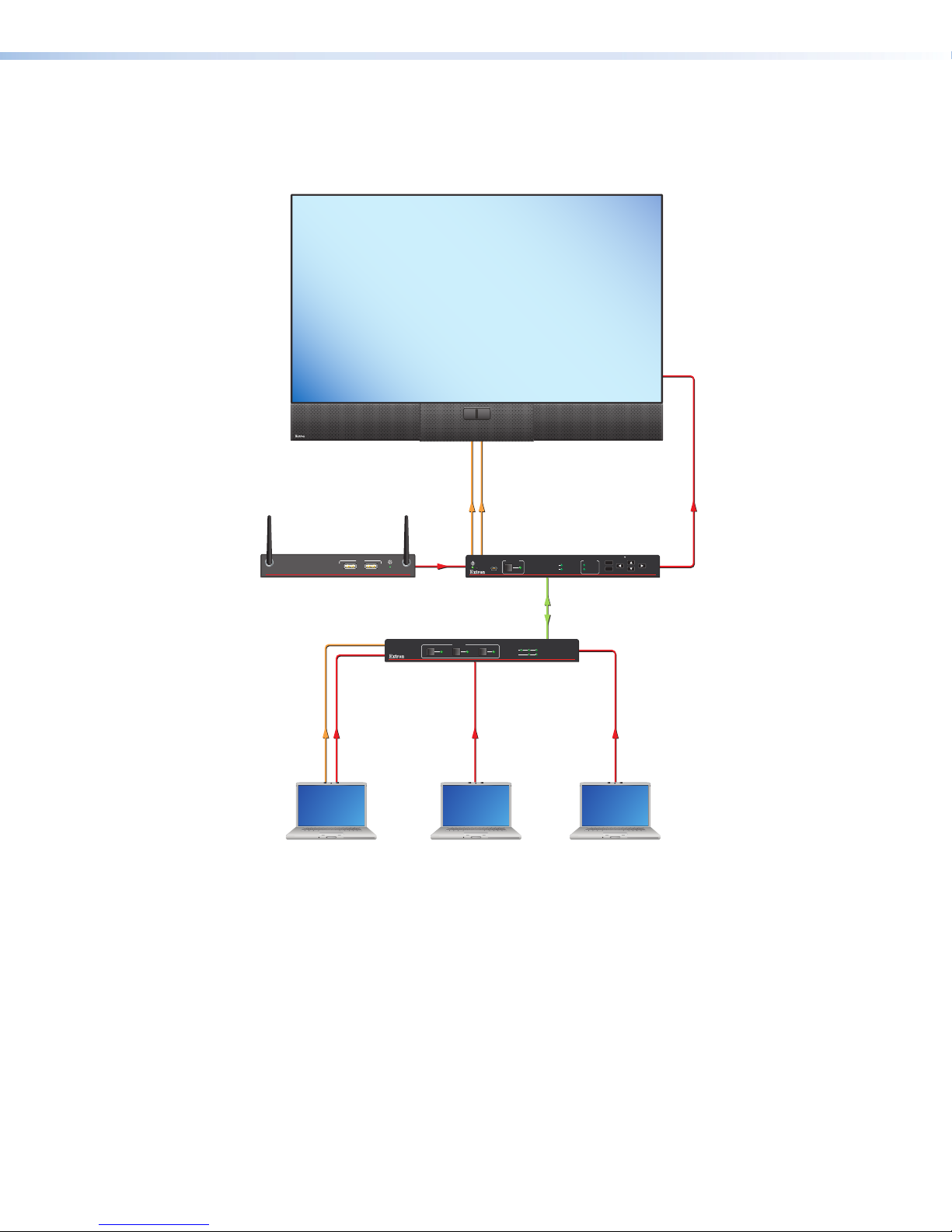
Application Example
The following diagram shows a typical SB 33 A Series installation.
55'' Display
Extron
SB 33 A 55-65
Sound Bar
Analog Audio
HDMI/CEC
ANT A ANT B
Extron
1 2
USB
ShareLink 250 W
Extron
ShareLink 250 W
Wireless Collaboration
HDMI
R
CONFIG
Extron
HC 404
Receiver
INPUT AUDIO
1
1
SIGNAL
HDCP
CATx Ca bl e
up to 230' (70m)
HOLD FOR 720p/1080p
MENU
LPCM-2CH
MULTI-CH
ENTER
HCR 102
Gateway
INPUTS
2
3 4
2 3 4
SIGNAL
HDCP
HCT 103
Extron
HC 404
Transmitter
Analog Audio
Laptop
VGA
Laptop Laptop
HDMIHDMI
Figure 3. An Example of a SB 33 A System Installation
SB 33 A Series User Guide • Introduction 2
Page 9
Installation
Topics covered in this section of the guide include the following:
• Installation Overview
• Mounting Instructions
• SMK V SB 33 VESA Mounting Kit
Installation Overview
The installation of the SB 33 A speaker includes using the included wallplate to mark the
wall where the SB 33 A will be mounted. After the wallplate is attached to the wall the
SB 33 A is then attached to the wallplate. The following section describes the mounting
procedure for safely and securely mounting the speaker.
NOTE: Install the wallplate onto wall material using common installation methods with
applicable hardware dictated per local building code.
Mounting Instructions
WARNING: Risk of personal injury or property damage. The final installation
should be able to continuously support the speaker weight. The final installation
should also be able to support any short term overloading. Since applications can
vary considerably, it is assumed that the installer will exercise good judgment when
selecting the mounting location, method, and hardware. Installation and service must
be performed by authorized personnel only.
AVERTISSEMENT : Risque de dommages corporels ou matériels.
L’installation finale doit pouvoir supporter en permanence le poids de l’enceinte.
L’installation finale doit également supporter toute surcharge temporaire. Étant donné
la possibilité d’évolution considérable des applications, il est supposé que l’installateur
fera preuve de discernement lors de la sélection de l’emplacement, du mode, et
du matériel de montage. L’installation et la maintenance du système doivent être
exclusivement effectuées par le personnel autorisé.
NOTE: Observe all applicable building codes and local ordinances when installing the
SB 33 A speaker.
SB 33 A Series User Guide • Installation 4
Page 10

Installing the Wallplate on a Non-masonry Wall
NOTE: When attaching the wallplate to masonry, see Installing the Wallplate on a
Masonry Wall in the following section.
1. Position and level the included wallplate (see figure 4) under the display screen (see
figure 5) and mark the locations of the wall studs through the top vertical slots and
bottom horizontal slots where screws (not included) will secure the SB 33 A speaker
wallplate to the wall.
NOTES:
• If the wallplate cannot be attached to two studs, the wallplate can be offset
such that one side of the wallplate can be attached to one stud and the other
end of the wallplate can be attached to the wall using two (not included)
1/4" Kap Toggles. If the stud must come down the middle of the wallplate,
secure the wallplate to the stud using two screws and to the wall using two
(not included) 1/4" Kap Toggles (one on the leftmost top slot and one on the
rightmost top slot)
• The center of the wallplate does not need to be precisely aligned with the
center of the display above it because the speaker module on either end of the
wallplate can be adjusted on the wallplate.
2. If necessary, cut a hole in the wall to route cables to the SB 33 A speaker.
Figure 4. Positioning the Wallplate
Display
Left Speaker ModuleCenter
Right Speaker Module
Figure 5. Display Screen and SB 33 A Alignment
NOTE: Assuming that the display screen is level, allow for some space between
the bottom of the display screen and the top of the speaker because the speaker
assemblies and the center bracket attach to the wallplate by hooking the top
mounting clasps of the speaker assemblies and center bracket over the top
mounting rail of the wall plate.
SB 33 A Series User Guide • Installation 5
Page 11

NOTE: To allow sufficient clearance between the top of the SB 33 A and the display
k
screen above it, allow for at least a minimum clearance of 11/16 inches (17.5 mm)
between the highest part of the top rail of the wallplate and the top of the speaker,
as shown below. The display screen should not encroach into this area above the
top rail.
Minimum clearance between top of wallplate
and bottom of display is 11/16" (17.5 mm).
11/16"
(17.5 mm)
Wall
Wallplate
REMOTE
OUTPUT
L SPEAKER
CLASS 2 WIRING
INPUTS
MAX
0.7A
POWER
12V
Side View
LEVEL BASS TREBLE
CG
V
10V 50mA
R
L
R
L
Figure 6. Positioning the Wallplate
3. Before starting the installation, remove the center section assembly from the packaging
and disassemble as indicated in the following order:
Center Bracket
Lock Washers (2)
Center Section Cover
Grille Hoo
Web Camera
Mount
Screws (2)
Screws (2)
Grille
Figure 7. Disassembling the Center Section Assembly
SB 33 A Series User Guide • Installation 6
Page 12
a. The front grille from the center section cover using a grille hook.
b. The center section cover from the center bracket standoffs by removing the 2
screws
c. The web camera mount from the center bracket (if necessary) by removing the two
screws and lock washers that attach it to the center bracket.
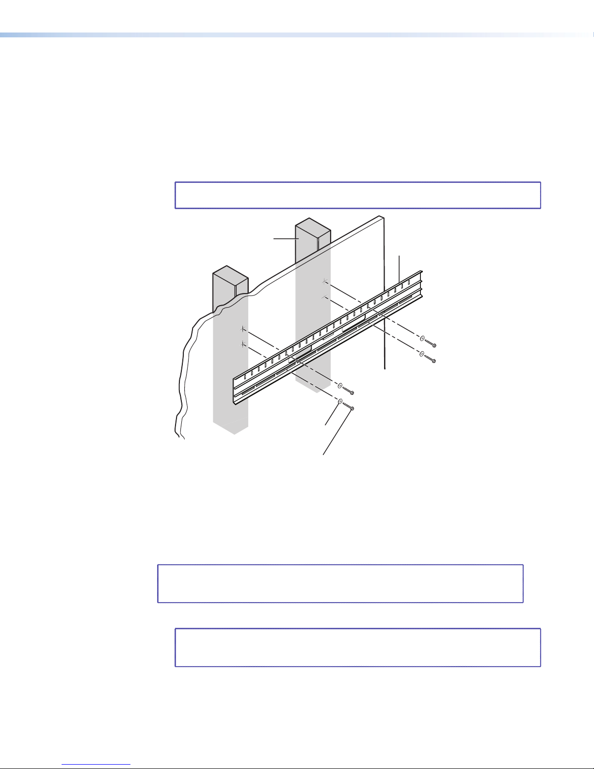
4. Drill four pilot holes through the marked locations on the wall.
5. Screw the wallplate to the wall studs using four #14 x 1 3/4" self-tapping wood or
metal screws and four 1/4" SAE washers into the pilot holes.
NOTE: Use wood or metal screws depending on whether the studs are wood or
metal.
Wall Stud
Wallplate
1/4" SAE Washer (x4)
#14 x 1 3/4" Self-tapping
Metal/Wood Screws (x4)
Figure 8. Attach the Wallplate to Studs
Installing the Wallplate on a Masonry Wall
Mount the wallplate on a brick, stone, or concrete wall by doing the following:
NOTE: The center of the wallplate does not need to be precisely aligned with the
center of the display above it because the speakers on either end of the wallplate
may still be adjustable on the wallplate.
1. Follow steps 1 to 3 of Installing the wallplate on a non-masonry wall on page 5.
NOTE: Because masonry installation does not involve wall studs, position the
wallplate so that the mounting holes will evenly distribute the weight of the
SB 33 A.
SB 33 A Series User Guide • Installation 7
Page 13
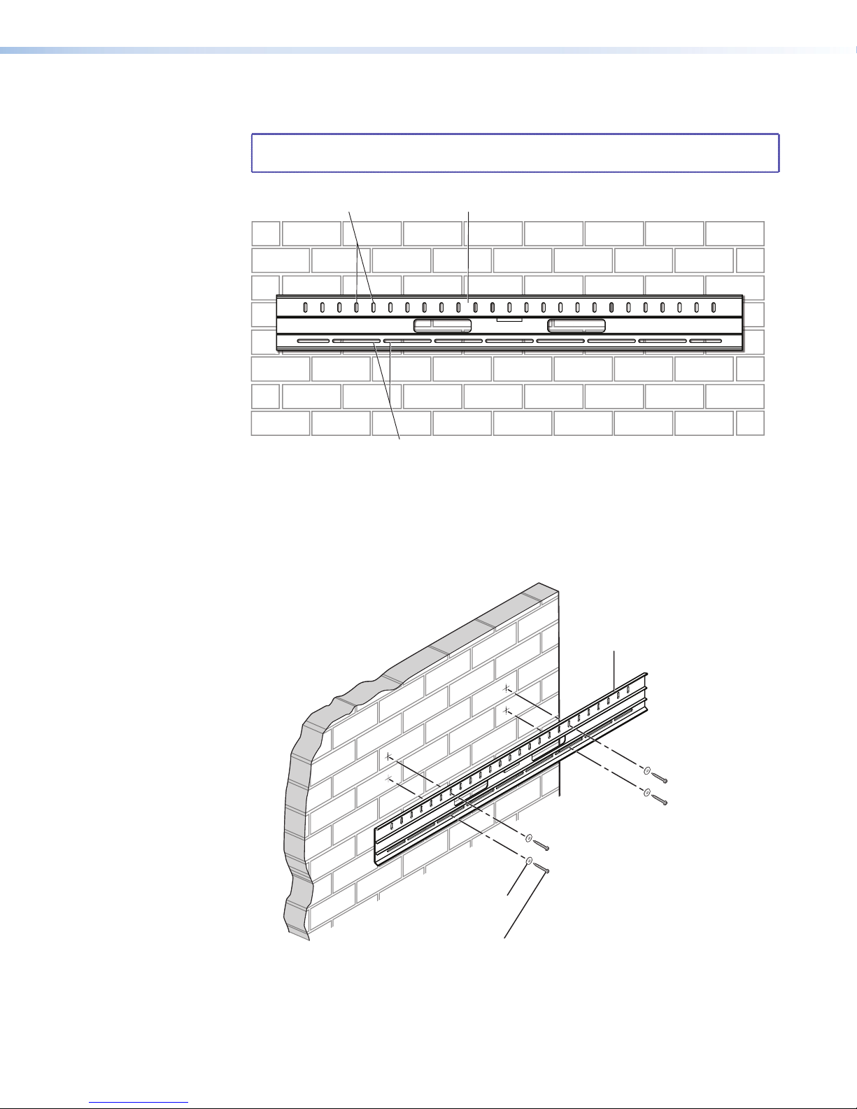
2. Using a masonry drill bit, drill four pilot holes in the masonry wall at the locations you
Mounting Holes
Wallplate
Masonry Screws (x4)
marked in step one.
NOTE: If you drill the pilot hole too shallow, the screw head might break off while
it is being fastened into the hole.
Mounting Holes
Figure 9. Positioning the Wallplate on Masonry
3. For each pilot mounting hole:
a. Insert a 1/4" x 1 3/4" masonry screw through a 1/4" SAE washer.
b. Position the wallplate over the pilot holes
c. Insert each screw and washer through the wallplate and into the pilot hole.
Wallplate
1/4" SAE Washer (x4)
1/4" x 1 3/4"
Figure 10. Attaching the Wallplate to Masonry
d. Securely tighten the four screws to the wallplate.
SB 33 A Series User Guide • Installation 8
Page 14

Attaching the SB 33 A to the Wallplate
)
ATTENTION:
• When attaching either speaker assembly or the center section to the wallplate, avoid
damaging or scratching the speaker assembly and center section cover.
• Lorsque vous xez les enceintes ou la section centrale à la plaque murale, prenez garde
à ne pas endommager ni à rayer les enceintes et le couvercle de la section centrale.
1. Hook the top clasp edge of the left speaker assembly over the top rail 1 in figure 11 of
the wallplate and slide it to left end of the wallplate 2 so that the left end of the speaker
assembly is aligned with the left end of the display.
Tighten the 2 set screws 3 on the bottom of the left speaker assembly to the bottom
rail of the wallplate.
11
Wall Wall
DISPLAY
22
Left Speaker
Wallplate
Left Speaker
Wallplate
Side View Side ViewFront View
Figure 11. Attaching the Left Speaker to the Wallplate
2. Hook the top clasp edge of the right speaker assembly over the top rail 1 in figure 12
of the wallplate and slide it to right end of the wallplate 2 so that the right end of the
speaker assembly is aligned with the right end of the display.
Tighten the 2 set screws 3 on the bottom of the right speaker assembly to the bottom
rail of the wallplate.
Screws (2)
3
3
11
CLASS 2 WIRING
REMOTE
CG
V
10V 50mA
OUTPUT
L SPEAKER
LEVEL BASS TREBLE
INPUTS
R
L
R
L
MAX
0.7A
POWER
12V
Wall
REMOTE
C G
V
10V 50mA
OUTPUT
BASS TREBLE
L SPEAKER
LEVEL
CLASS 2 WIRING
INPUTS
R
L
R
L
MAX
7A
0.
12V
POWER
DISPLAY
Wall
22
Wallplate
Figure 12. Attaching the Right Speaker to the Wallplate
Right Speaker
Wallplate
Right Speaker
Side View Side ViewFront View
SB 33 A Series User Guide • Installation 9
33
Screws (2
Page 15

3. Route the supplied power cable from the power supply in the left speaker enclosure to
Left Speaker Module
Right Speaker Module
the power input connector of the amplifier in the right speaker enclosure.
REMOTE
CG
V
10V 50mA
OUTPUT
L SPEAKER
CLASS 2 WIRING
LEVEL BASSTREBLE
INPUTS
R
L
R
L
MAX
0.7A
POWER
12V
Amplifier
Power Supply
DC Power
Outputs
DC Power Cord
Captive Screw
Connectors
POWER
12V
0.7A MAX
DC Power
Input
Tie
Wraps
Figure 13. Power Supply to Amplifier Cable Routing
ATTENTION:
• Always use a power supply supplied by or specied by Extron. Use of an
unauthorized power supply voids all regulatory compliance certication and may
cause damage to the supply and the end product.
• L’utilisation d’une source d’alimentation non autorisée annule toute certication de
conformité réglementaire, et peut endommager la source d’alimentation et l’unité.
• The installation shall be in accordance with the applicable provisions of National
Electrical Code ANSI/NFPA 70, article 725 and the Canadian Electrical Code part1,
section 16.
• Cette installation doit toujours être conforme aux dispositions applicables du Code
américain de l’électricité (National Electrical Code) ANSI/NFPA 70, article 725, et du
Code canadien de l’électricité, partie 1, section 16.
• The length of the exposed wires in the stripping process is critical. The ideal length
is 3/16 inches (5 mm). Any longer and the exposed wires may touch, causing a short
circuit between them. Any shorter and the wires can be easily pulled out even if
tightly fastened by the captive screws.
• La longueur des câbles exposés est primordiale lorsque l’on entreprend de les
dénuder. La longueur idéale est de
5 mm (3/16 inches). S’ils sont trop longs, les câbles exposés pourraient se toucher
et provoquer un court-circuit. S’ils sont trop courts, ils peuvent être tirés facilement,
même s’ils sont correctement serrés par les borniers à vis.
NOTE: Do not tin the wires. Tinned wire does not hold its shape and can become loose
over time.
SB 33 A Series User Guide • Installation 10
Page 16

4. Route the supplied speaker cable from the left speaker module to the left speaker
INPUTS
OUTPUT
V
LEVEL BASS TREBLE
C
10V 5
CLASS 2 WIRING
L SPEAKER
e
INPUTS
L
L
R
LEVEL
R
POWER
12V
0.7A MAX
INP
output of the amplifier (2), as shown below.
Right Speaker Amplifier
Side View
Speaker Cable
Power Cable
e
Speaker Cable
Front View
22
Audio Input
Connectors
Left Speaker Cable
Output
Amplifier
1
1
Figure 14. Left Speaker Cable Routing
5. Hook the top clasp edge of the center bracket over the top rail (1) of the wallplate and
slide it to center of the display.
Side View
11
Wall
Figure 15. Center Bracket to Wallplate Installation
Tighten the two set screws (2) on the bottom of the center bracket to the bottom rail of
the wallplate.
NOTE: If a camera is to be mounted to the center bracket, see Mounting a
Camera before proceeding to the next step.
Mounting a Camera
The SB 33 A speaker can accommodate a camera mounted to the center bracket. A
small webcam can be mounted behind the center cover, and a larger PTZ camera can be
mounted in front of the center cover using an optional PTZ camera shelf.
NOTE: If mounting a PTZ Camera, please go to Mounting a PTZ Camera wiith
optional PTZ camera shelf section. Both the webcam camera shelf and the PTZ
camera shelf use the same two attaching screws and lock washers.
Wallplate
Center Bracket
Wall
22
Screws (2)
Side View
SB 33 A Series User Guide • Installation 11
Page 17

Camera mounting behind the front cover
POWER
12V
0.7A MAX
INP
POWER
12V
0.7A MAX
INP
A webcam can be installed using the included webcam shelf.
1. Install the webcam shelf by attaching it to the center bracket using 2 screws going
through the 2 vertical slots on the shelf and into two mounting holes in the bracket.
There are 2 pairs of available holes in the bracket. The shelf height can be adjusted by
positioning the screws in the shelf slots 1.
NOTE: For cameras that require more overhead clearance, the webcam shelf can
be inverted (see Option 2 below right).
Center
Bracket
11
Web Camera
Mount
Lock Washers (2)
Screws (2)
Option 2
Figure 16. Inverting the Webcam Shelf
2. A screw is inserted in the bottom slot of the shelf 2 to secure the webcam.
Webcam
22
Screw
Figure 17. Securing the Webcam to Shelf
3. See Attaching Power and Audio Sources to the SB 33 A on page 15 to continue
the installation.
SB 33 A Series User Guide • Installation 12
Page 18

Mounting a PTZ camera with optional PTZ camera shelf
POWER
12V
0.7A MAX
INP
POWER
12V
0.7A MAX
INP
POWER
12V
0.7A MAX
INP
Lock Washers (2)
A larger PTZ camera that takes up more space can be installed in front of the front cover
using the optional PTZ camera shelf. Follow the steps below.
ATTENTION:
• The PTZ camera cannot exceed 4 lbs. (1.81 kg).
• La caméra PTZ ne peut peser plus de 1,81 kg (4 lb).
PTZ Camera
Figure 18. PTZ Camera on PTZ Camera Shelf
1. Install the PTZ camera shelf by attaching it to the center bracket using two screws and
lock washers going through the vertical slots on the shelf and into two mounting holes
in the bracket. There are two pairs of available holes in the bracket. The shelf height
can be adjusted by positioning the screws in the shelf slots.
Center
Bracket
Screws (2)
PTZ Camera Shelf
Figure 19. Attaching the PTZ Camera Shelf
SB 33 A Series User Guide • Installation 13
Page 19

2. To install a PTZ camera, follow the steps below:
POWER
12V
0.7A MAX
IN
P
Zip Tie
POWER
12V
0.7A MAX
INP
k
PTZ Cables
2
2
1
1
Cable
Tie-off
Point
3
3
44
Figure 20. Routing the PTZ Camera Cable
a. Route the PTZ cable to the PTZ camera through the center section cover (1) and
along a center bracket cable tie-off point (2).
b. Route the cable to the camera shelf (3).
c. Route the cable through the access hole at the rear of the camera shelf (4).
3. See Attaching Power and Audio Sources to the SB 33 A on page 15 before
continuing with the next steps.
4. If the optional blank grille is being installed, see Attaching the optional blank grille on
page 19.
5. Slide the center section cover over the center bracket and attach the two cover screws
to the center bracket standoffs being careful not to overtighten the screws.
Figure 21. Attaching the Center Section Cover
Center Section Cover
Grille Hoo
Grille
Center Bracket
Standoff
Screws (2)
SB 33 A Series User Guide • Installation 14
Page 20

6. Attach the grille to the center section cover. See the illustration above.
IN
P
IN
POWER
12V
0.7A MAX
I
NP
PTZ Camera
Left Speaker/Power Supply
NOTE: Two grille hooks are included to facilitate grill removal while avoiding damage
to the grille. It is best to insert the hook along the top or bottom outer edge of the
grille, as shown above.
7. Route the cable to the PTZ camera (1) and attach it to the camera. See the figure
below.
8. Place the camera on the shelf and attach it to the shelf with the mounting screw (2).
See the figure below.
PTZ Cables
Final View
11
Screw
2
2
Figure 22. Attaching the PTZ Camera to the Shelf
Attaching Power and Audio Sources to the SB 33 A
The SB 33 A has a power supply for the amplifier housed in the left speaker enclosure. The
power supply has an AC power input connector (A) and a DC power output connector (B)
that routes power to the amplifier. See the illustration below.
(Side View)
AABB
Figure 23. AC Input and DC Output Power Connectors
This section describes how the power and audio sources are attached to the SB 33 A, as
shown in the following steps.
SB 33 A Series User Guide • Installation 15
Page 21

AA
F
F
G
G
e
Front View
Power Supply
NOTE: Speaker and DC power cables must be routed before attaching the center bracket to
the wallplate. See the previous section.
Power Cord
Amplifier Module (inside Right Speaker module)
Audio Input Cable
e
1
Left Speaker Module Wires
DC Power Cable
Figure 24. Speaker and DC Power cable routing
CLASS 2 WIRING
OUTPUT
POWER
12V
0.7A
L SPEAKER
MAX
L
L
R
INPUTS
R
LEVEL BASS TREBLE
V
CG
10V 50mA
HH
REMOTE
BBCCDDEE
Figure 25. SB 33 A Amplifier Front Panel
Power LED
A
B Amplifier power supply connector F Level, bass, and treble
C Captive screw balanced or
unbalanced audio input connector
D RCA unbalanced stereo input
connectors
For a detailed description of the above connectors go to the SB 33 A Internal Amplifier
Front Panel (inside right speaker module) section of the Operation chapter on page 27.
E 3.5 mm unbalanced stereo input jack
potentiometers
G Remote volume control connector
H Left Speaker output receptacle (to
left speaker)
SB 33 A Series User Guide • Installation 16
Page 22

1. Wiring access points for the power and speaker cables to the SB 33 A are shown
e
INPUTS
L
L
R
LEVEL
R
below.
Top Cable Access Points Bottom Cable Access Point Back Cable Access Points
Access Points
Wallplate
Figure 26. Power and Speaker Cable Routing
Cables can be be secured with zip ties to cable tie off points located on the center
bracket, as shown below.
Zip Tie
e
Front View
Cable Tie-off Point
Figure 27. Securing Cables with Zip Ties
2. Route the audio cable from the display to the audio input connectors of the power
amplifier (1) in the right speaker assembly. See the cable access points illustration in
step 1.
Display
Speaker Cable
Power Cable
Speaker Cable
Front View
Audio
Cable
Audio Input
Connectors
Right Speaker Amplifier
Amplifier
11
Side View
Figure 28. Routing Speaker Cables from the Display
SB 33 A Series User Guide • Installation 17
Page 23

3. Connect the power cord to the power supply in the left speaker assembly (1), as
e
INPUTS
OUTPUT
V
LEVEL BASS TREBLE
C
10V 5
CLASS 2 WIRING
L SPEAKER
POWER
12V
0.7A MAX
INP
shown below.
Power Cord
Audio Input Cable
Amplifier Module (inside Right Speaker module)
22
e
1
Figure 29. Connecting Power to the Power Supply
4. Set the level, bass, and treble potentiometers shown above (2) appropriately.
Attaching the Center Section Cover
1. Slide the center section cover over the center section and attach the two cover screws
to the center bracket standoffs being careful not to overtighten the screws.
Center Bracket
Level, Bass,
Treble
Potentiometers
Figure 30. Attaching the Center Section Cover and Grille
2. Attach grille to the center section cover (see the above illustration).
NOTE: Two grille hooks are included to facilitate grill removal while avoiding damage
to the grille. It is best to insert the hook along the outer edge of the grille.
Center Section Cover
Grille
Screws (2)
SB 33 A Series User Guide • Installation 18
Page 24

Attaching the Optional Blank Grille
r
The optional blank grille can be attached to the center section cover by following the steps
below.
1. If a grille is attached, use the grille hooks to remove the grille.
NOTE: Two grille hooks are included to facilitate grille removal while avoiding
damage to the grille. It is best to insert the hook along the outer edge of the grille.
2. Remove the four screws that attach the center section cover doors to the center
section cover. Two door rails behind the cover and the sliding doors will be separated
from the center section cover after the screws are removed.
Center Section
Webcam Doors and Door Rails
Center Section Cove
Grille
Screws (4)
Figure 31. Attaching the Blank Grille
3. Remove the center section webcam doors and door rails (not shown).
4. Attach the blank grille to the center section cover.
SB 33 A Series User Guide • Installation 19
Page 25

SMK V SB 33 VESA Mounting Kit
The SMK V SB 33 VESA Mounting Kit allows the SB 33 A Series speaker to be attached
to the same VESA display mount that supports the display device. This type of installation
enables the SB 33 speaker to be aligned with the display for a visually aesthetic installation.
The SB 33 front speaker surface can be adjusted flush with the front of the display. It can be
adjusted forward, backward, up, down, and side-to-side.
Installation
VESA display mounts come in a variety of different styles, so these instructions for installing
the SMK V SB 33 VESA Mounting Kit are variable. Please consult the installation guides for
your specific VESA display mount and your display device before installing our kit. Follow
the steps below to install the kit.
WARNING: Risk of personal injury or property damage. The final installation should
be able to continuously support the speaker weight. The final installation should also
be able to support short term overloading. Be sure to not exceed the load limit of the
VESA mount, mounting surface, and SMK V SB 33. The maximum load limit of the
SMK V SB 33 is 85 lb. (38 kg) Since applications can vary considerably, it is assumed
that the installer will exercise good judgment when selecting the mounting location,
method, and hardware. Installation and service must be performed by authorized
personnel only.
AVERTISSEMENT : Risque de dommages corporels ou matériels. L’installation
finale doit pouvoir supporter en permanence le poids de l’enceinte. L’installation finale
doit également pouvoir supporter une courte surcharge. Veillez à ne pas dépasser
la charge maximale du support de montage VESA, de la surface de montage, et de
l’unité SMK V SB 33. La charge maximale du SMK V SB 33 est de 38 kg. Étant donné
la possibilité d’évolution considérable des applications, il est supposé que l’installateur
fera preuve de discernement lors de la sélection de l’emplacement, du mode, et
du matériel de montage. L’installation et la maintenance du système doivent être
exclusivement effectuées par un technicien agréé.
NOTE: Observe all applicable building codes and local ordinances when installing the
SB 33 A speaker.
The SMK V SB 33 VESA Mounting Kit is composed of 2 long L-brackets, 2 short
L-brackets, 6 bolts, 6 lock washers, 2 washers, and 6 wingnuts.
1. Install the wall mount portion of the VESA display mount onto the desired wall location.
See the VESA display mount installation guide.
SB 33 A Series User Guide • Installation 20
Page 26

2. Position one long L-bracket of the SB 33 kit on the back of the display while aligning
the bolt hole on the display with a slot on the L-bracket. Repeat this procedure for the
other long L-bracket on the other side of the display.
Long L-brackets
Figure 32. Positioning Long L-brackets on Display
3. Place the VESA display mount on top of the L-bracket while aligning the bolt hole of the
display mount with the slot of the L-bracket and the bolt hole of the display. Repeat this
procedure for the other long L-bracket on the other side of the display.
VESA Display
Mount (not included)
Mounting Screws
Washers
Spacers
Long L-brackets
Figure 33. Aligning VESA Display Mount to Long L-brackets
4. Insert bolts through the VESA display mounts, the long L-brackets, and the display. Be
sure to the align the bolt holes of the VESA display mounts with the display mounting
holes and insert the bolts. Tighten all 4 bolts. Spacers are provided if needed. See the
illustration in step 3.
SB 33 A Series User Guide • Installation 21
Page 27

Wallplate
Wingnut
Short L-bracket
Long
L-bracket
Short
L-bracket
5. Position the short L-bracket under the long L-bracket that was installed in step 4
above such that the L bends of each bracket are paired together. See the illustration
below. Then install 1 bolt with a wingnut and lockwasher (included in the kit) so that the
long L-bracket and short L-bracket are held together. Tighten the wingnut. Repeat this
procedure for the other long L-bracket on the other side of the display.
NOTE: The short L-bracket may be reversed if the SB 33 speaker needs to be
positioned further forward relative to the display above it. See the illustration
below right.
Lock
Washer
Short
L-bracket
(Reversed)
Bolt
Alternative Installation of
Figure 34. Attaching Short L-brackets
6. Install the SB 33 speaker wallplate to the short L-bracket using 2 bolts, 2 lock washers,
and 2 wingnuts, as shown below. Repeat this procedure for the other short L-bracket
on the other side.
Long
L-bracket
Bolt
Wingnut
Lock
Washer
Short
L-bracket
Figure 35. Installing Short L-brackets
SB 33 A Series User Guide • Installation 22
Page 28

7. To adjust the SB 33 vertically:
VESA Display
Mount
a. Loosen, but do not remove, the bolts that attach the long L-brackets to the display.
Long
L-bracket
Washer
Bolt
Vertical Adjustment
Figure 36. Loosening Long L-brackets Bolts
CAUTION: If the display is already attached to the wall, the display could
detach from the VESA mount if this adjustment is made. It is highly
recommended that this adjustment be done prior to attaching the display to
the wall.
ATTENTION: Si l’écran est déjà fixé au mur, il peut être détaché du support
de montage VESA si ce réglage est effectué. Il est vivement recommandé
d’effectuer ce réglage avant de fixer l’écran au mur.
b. Adjust the SB 33 to the desired distance from the display and then tighten the
bolts.
SB 33 A Series User Guide • Installation 23
Page 29

NOTE: Assuming that the display screen is level, allow for some space between
the bottom of the display screen and the top of the speaker because the
speaker assemblies and the center bracket attach to the wallplate by
hooking the top mounting clasps of the speaker assemblies and center
bracket over the top mounting rail of the wall plate.
To allow sufficient clearance between the top of the SB 33 A and the display
screen above it, allow for at least a minimum clearance of 0.69 inches (17.5
mm) between the highest part of the top rail of the wallplate and the top of
the speaker, as shown below. The display screen should not encroach into
this area above the top rail.
11/16"
(17.46 mm)
Wall
Wallplate
OUTPUT
CLASS 2 WIRING
L SPEAKER
POWER
REMOTE
INPUTS
MAX
0.7A
12V
CG
V
10V 50mA
LEVEL BASS TREBLE
R
L
R
L
Side View
SB 33 A Series User Guide • Installation 24
Page 30

8. Fasten the display onto the VESA wall mount that was attached in step 1.
SB 33 A Speaker
9. Install the SB 33 A speaker to the wallplate. If the alignment between the display and
the SB 33 speaker needs to be adjusted, see the following section.
Long
L-bracket
Short
L-bracket
Wallplate
Display
Figure 37. Installing the SB 33 A to the Wallplate
SB 33 A Series User Guide • Installation 25
Page 31

Aligning the SB 33 Speaker to the Display
Short
L-bracke
The SMK V SB 33 VESA Mounting Kit can be adjusted to align the SB 33 speaker assembly
relative to the front of the display, from front to rear (depth).
Front to rear (depth) adjustment
1. Loosen, but do not remove, the two wingnuts that attach the long L-brackets to the
short L-brackets.
t
Depth Adjustment
Long
L-bracket
Figure 38. Front to Rear Depth Adjustment
2. Adjust the SB 33 either to the front or to the rear of the display and then tighten the
wingnuts.
SB 33 A Series User Guide • Installation 26
Page 32

Operation
AA
Topics covered in this section of the guide include the following:
• SB 33 A Internal Amplifier Front Panel
• Front Panel Controls
SB 33 A Internal Amplifier Front Panel (inside right speaker module)
H
H
REMOTE
OUTPUT
CG
V
10V 50mA
G
G
CLASS 2 WIRING
L SPEAKER
INPUTS
POWER
12V
LEVEL BASS TREBLE
E
E
R
D
D
L
R
C
L
MAX
0.7A
C
BB
FF
Figure 39. The Front Panel of the SB 33 A Amplifier
Power LED
A
E 3.5 mm unbalanced stereo input jack
B Amplifier power supply connector F Level, bass, and treble
potentiometers
C Captive screw balanced or
unbalanced audio input connector
D RCA unbalanced stereo input
connectors
G Remote volume control connector
H Left Speaker output receptacle (to
left speaker)
SB 33 A Series User Guide • Operation 27
Page 33

Power LED — The LED lights green when the amplifier is receiving power and active. It
Left Speaker Module
Right Speaker Module
LR
Slee
Slee
Balanced Mono Input
LR
Unbalanced Mono Input
Slee
Tip (+)
RCA Connector
3.5 mm TRS Connector
A
lights amber when the unit is powered down (after 25 minutes of inactivity).
Amplifier power supply connector — Connect one end of the DC power cord to one
B
of the two pole, 3.5 mm captive screw outlets on the power supply. Connect the other
end into the power receptacle on the rear panel of the amplifier, as shown in figure 40
below. The power cord connectors are correctly wired when shipped.
REMOTE
CG
V
10V 50mA
OUTPUT
L SPEAKER
CLASS 2 WIRING
LEVEL BASSTREBLE
INPUTS
R
L
R
L
MAX
0.7A
POWER
12V
Amplifier
Power Supply
DC Power
Outputs
DC Power Cord
Captive Screw
Connectors
POWER
12V
0.7A MAX
DC Power
Input
Tie
Wraps
Figure 40. Power Supply to Amplifier Cable Connection
Captive screw balanced or unbalanced audio input connector — This 5-pole
C
3.5 mm captive screw receptacle accepts line level, balanced or unbalanced, mono
or stereo audio signals. See the attention (on page 10) and note (on page10) for
important information about connecting wires to captive screw connectors.
Tip
Tip
LR
ve
ve
Tip
Ring
Sleeves
Tip
Ring
Unbalanced Stereo Input
Tip
ve
RCA unbalanced stereo input connectors — These receptacles accept unbalanced,
D
LR
Balanced Stereo Input
Tip
Ring
Sleeve
line level audio signals. The input can be stereo, using two RCA connectors, or mono,
using a single RCAconnector plugged into the left receptacle.
Sleeve ( )
If unused, the receptacles automatically terminate to lower the noise floor.
3.5 mm unbalanced stereo input jack — This input also accepts unbalanced, line
E
level audio signals through a 3.5 mm tip-ring-sleeve (TRS) stereo connector. If unused,
the receptacle automatically terminates to lower the noise floor.
Tip (L)
Ring (R)
Sleeve ( )
SB 33 A Series User Guide • Operation 28
Page 34

Level, Bass, and Treble potentiometers — Three front panel potentiometers are
REMOTE
Ground (Pin 3)
V
10k ohm
F
used to optimize input level, bass, and treble settings.
Remote volume control connector — This 3-pin, captive screw port allows an audio
G
controller to control volume and mute levels remotely. See Remote Control Options
on page 11 if using a MediaLink controller.
VCG
10V50mA
Left Speaker output receptacle (to left speaker) — This 2-pole, 5 mm screw lock
H
captive screw receptacle is used to connect the amplifier to the left speaker.
CLASS 2 WIRING
L SPEAKER
OUTPUT
The amplifier produces up to 15watts per channel.
See the attention (page 5) and note (page 5) for important information about
connecting wires to captive screw connectors.
ATTENTION:
• Do not short or ground the speaker outputs as this will damage the amplifier.
• Ne pas mettre à la terre ni provoquer de court-circuit dans les sorties de
l’enceinte, afin d’éviter tout risque de détérioration de l’amplificateur.
Wiring for remote control
Options for remote control include the Extron VC50, VCM110AAP, VCM200 series, and
MLAVC10 Plus. Third party 10k potentiometer volume controllers can also be connected to
this port.
Figure 41 and the descriptions below show the wiring for the VCM 100 MAAP. Wiring other
remote control connectors is similar.
REMOTE
VCG
10V 50mA
Vol/Mute
(Pin 2)
olume Pot
s
10 V (Pin 1)
2k ohms
Mute
Switch
Figure 41. Remote Control Connector
SB 33 A Series User Guide • Operation 29
Page 35

Audio Output
-
Left
Right
• Pin 1 is for 10 VDC reference voltage output.
• Pin 2 (C) has two functions:
• Volume control: it can be used as a variable voltage input between 0 and 10 VDC,
with 0 V giving full attenuation and 10 V giving maximum volume.
• Mute: it can be used for remote control muting. Sound is muted while this pin is
shorted to ground.
• Pin 3 is for the ground connection.
NOTE: All nominal levels are at ±10%.
This 2-pole, 5 mm screw lock captive screw receptacle is used to connect the amplifier to
the left speaker. The amplifier produces up to 15watts per channel.
CLASS 2 WIRING
L SPEAKER
OUTPUT
Captive
Screw
RCA
TRS
Captive
Screw
RCA
TRS
+
+
+
+
+
+
+
+
+
+
Stereo
Stereo
Amp Stage
Figure 42. Amplifier Output Channels
Signal flow is as follows:
1. The SB 33 A sums and weights the left unbalanced signals from the TRS and RCA
receptacles. This summed, unbalanced signal is then summed with the left balanced
signal from the captive screw receptacle.
2. The right channel is handled in the same way.
3. The left and right stereo channels are sent to the left and right output amplifers
respectively
The captive screw, RCA, and TRS inputs are buffered.
SB 33 A Series User Guide • Operation 30
Page 36

Internal Adjustments
LEVEL BASS TREBLE
This section describes how to set the level, bass, and treble potentiometers on the SB 33 A
(located on the panel inside the right speaker module).
Figure 43. Level, Bass, and Treble knobs (located inside right speaker module)
Setting Input Level
Adjust the amplifier input level as follows:
1. Unplug the Remote plug from the unit.
2. Set the volume of the audio source to its minimum level.
3. Turn the Level potentiometer fully counterclockwise to its minimum setting.
4. Set the volume of the audio source to its maximum level. No sound should come out.
5. Slowly increase the amplifier level by rotating the Level potentiometer clockwise until
sound distortion starts. Lower the level slightly until the distortion disappears. At this
setting, whatever the volume setting of the audio source, no clipping should occur.
Setting Bass and Treble
Adjust the amplifier bass and treble as follows:
1. Use the Bass potentiometer to increase or decrease the bass shelving ±10 dB at 80 Hz
and below.
2. Use the Treble potentiometer to increase or decrease the treble shelving ±10 dB at
10kHz and above.
NOTE: Turning the Bass or Treble potentiometers counterclockwise will decrease the
output at the specified frequencies. Turning the potentiometers clockwise will increase
the output. When the potentiometer is in the center, flat response is achieved.
SB 33 A Series User Guide • Operation 31
Page 37

Reference
Information
Topics covered in this section of the guide include the following:
• Defeating the Auto Power-down Timer
• Troubleshooting
Defeating the Auto Power-down Timer
The auto power-down timer determines whether or not the amplifier enters standby mode.
The amplifier powers down if the input signal remains below the input signal detection
threshold for about 25 minutes.
The timer resets whenever the input signal exceeds the input signal detection threshold.
Resetting the timer starts a new 25 minute countdown until the amplifier powers down.
Resetting the timer also causes an amplifier that is already powered down to “wake up.”
There may be times when it is desirable to bypass the auto power-down timer. However,
this should be done as a last resort. Examples of when defeating the auto power-down
circuit might be required include:
• If the amplifier is used in a paging system. When the amplifier has already powered
down, the first syllable might be cut off as the amplifier wakes up from standby mode.
• If the input signal is so quiet that the level remains below the input signal detection
threshold for 25minutes, the timer would cut the audio in the middle of playback by
placing the amplifier into standby mode.
ATTENTION:
• The following procedure cannot be reversed and should be carried out as a last
resort. Be certain that you need to defeat the auto power-down timer before
continuing.
• La procédure qui suit est irréversible et doit être effectuée en dernier recours.
Veuillez désactiver le temporisateur de mise hors tension automatique avant de
continuer.
To defeat the auto power-down timer, follow these instructions:
1. Gain access to the front panel of the amplifier by removing the center section grille and
then the center section cover (see figure 30 on page 18).
2. Disconnect the power cable from the amplifier.
3. Disconnect all audio cables that attach to the amplifier.
4. Disconnect any connections to the remote input connector.
SB 33 A Series User Guide • Reference Information 32
Page 38

R SPEAKER
CLASS 2 WIRING
OUTPUT
)
3
Right Speaker
.
Enclosure
Amplifier
3
OUT
PUT
R SPEAKER
CLASS 2 WIRING
11
22
Screws (4
Speaker Cable
Figure 44. Disconnecting the Right Speaker Wire from the Amplifier
5. Loosen the two bottom screws that attach the right speaker enclosure to the wallplate
and remove it.
6. Disconnect the speaker wire from the amplifier side 1 that goes to the right speaker, as
shown above.
7. Remove the 4 screws that attach the amplifier to the right speaker enclosure 2 , as
shown above.
8. Remove the amplifier from the right speaker enclosure 3, as shown above.
9. Remove the 5 screws that secure the top cover of the amplifier (there are 2 screws on
each side panel and 1 on the top).
Figure 45. Removing the Top Cover of the Amplifier
ATTENTION:
OUTPUT
CLASS 2 WIRING
REMOTE
L SPEAKER
C G
V
TREBLE
10V 50mA
INPUTS
BASS
LEVEL
R
L
POWER
12V
MAX
0.7A
R
L
Screws (5)
• Exercise caution when removing the screws to avoid stripping the screw
heads.
• Soyez prudent en retirant les vis afin d’éviter d’abîmer les têtes de vis.
SB 33 A Series User Guide • Reference Information 33
Page 39

10. Slide the cover forward a little then lift the cover straight up and place it out of the way.
Resistor R42
The circuit boards are now exposed at the back.
ATTENTION:
• Do not touch the electronic components or the connectors on the backplane
or on the circuit boards without being electrically grounded.
• Ne pas toucher les composants électroniques ou les connecteurs sur la carte
mère ou sur les circuits imprimés sans être électriquement relié à la terre.
11. Identify resistor R42 at the back of the bottom circuit board.
Figure 46. Removing the R42 Resistor
12. Remove the resistor using a pair of diagonal cutters to clip the wires attaching it to the
circuit board.
13. Re-attach the top cover with the five screws that were removed in step 9.
14. Re-attach the amplifier to the right speaker enclosure using the four screws that were
removed in step 7.
15. Re-attach the speaker cable from the right speaker.
16. Re-attach the right speaker enclosure to the wallplate and tighten the two bottom
screws that were loosened in step 5.
17. Re-attach all power, VCM, and audio cables that were removed from the amplifier.
18. Re-attach the center section cover and center section grille that were removed in
step 1.
SB 33 A Series User Guide • Reference Information 34
Page 40

Troubleshooting
Amplifier Fails to Exit Standby Mode Promptly
Under different circumstances, the front panel LED lights green or amber to provide
diagnostic information.
Power LED
Color
Amber No output signal. No input detected: verify that there is an
Green No output signal. The amplifier may be in mute mode. Check
Green or
Amber
Problem Description Problem Solution
Slow to exit standby mode
when a signal is present.
Amplifier Enters Standby Mode Too Early
Power LED
Color
Green or
Amber
Problem Description Problem Solution
Enters standby mode
early.
input signal.
If a signal is present, raise the level of the
source signal.
the Remote port.
The input signal may be too weak. Raise the
level of the source signal.
The input signal may be too weak. Raise the
level of the source signal.
SB 33 A Series User Guide • Reference Information 35
Page 41

Extron Warranty
Extron Electronics warrants this product against defects in materials and workmanship for a period of five years
from the date of purchase. In the event of malfunction during the warranty period attributable directly to faulty
workmanship and/or materials, Extron Electronics will, at its option, repair or replace said products or components,
to whatever extent it shall deem necessary to restore said product to proper operating condition, provided that it is
returned within the warranty period, with proof of purchase and description of malfunction to:
USA, Canada, South America,
and Central America:
Extron Electronics
1230 South Lewis Street
Anaheim, CA 92805
U.S.A.
Europe:
Extron Europe
Hanzeboulevard 10
3825 PH Amersfoort
The Netherlands
Africa:
Extron South Africa
South Tower
160 Jan Smuts Avenue
Rosebank 2196, South Africa
This Limited Warranty does not apply if the fault has been caused by misuse, improper handling care, electrical
or mechanical abuse, abnormal operating conditions, or if modifications were made to the product that were not
authorized by Extron.
NOTE: If a product is defective, please call Extron and ask for an Application Engineer to receive an RA (Return
Authorization) number. This will begin the repair process.
USA: 714.491.1500 or 800.633.9876 Asia: 65.6383.4400
Europe: 31.33.453.4040 or 800.3987.6673 Japan: 81.3.3511.7655
Africa: 27.11.447.6162 Middle East: 971.4.299.1800
Asia:
Extron Asia Pte Ltd
135 Joo Seng Road, #04-01
PM Industrial Bldg.
Singapore 368363
Singapore
China:
Extron China
686 Ronghua Road
Songjiang District
Shanghai 201611
China
Japan:
Extron Electronics, Japan
Kyodo Building, 16 Ichibancho
Chiyoda-ku, Tokyo 102-0082
Japan
Middle East:
Extron Middle East
Dubai Airport Free Zone
F13, PO Box 293666
United Arab Emirates, Dubai
Units must be returned insured, with shipping charges prepaid. If not insured, you assume the risk of loss or damage
during shipment. Returned units must include the serial number and a description of the problem, as well as the
name of the person to contact in case there are any questions.
Extron Electronics makes no further warranties either expressed or implied with respect to the product and its quality,
performance, merchantability, or fitness for any particular use. In no event will Extron Electronics be liable for direct,
indirect, or consequential damages resulting from any defect in this product even if Extron Electronics has been
advised of such damage.
Please note that laws vary from state to state and country to country, and that some provisions of this warranty may
not apply to you.
Contact Information
Worldwide Headquarters: Extron USA West, 1025 E. Ball Road, Anaheim, CA 92805, 800.633.9876
 Loading...