

Page 1
Installation Guide
www.extron.com
Extron Electronics, USA
1230 South Lewis Street
Anaheim, CA 92805
USA
714.491.1500
Fax 714.491.1517
Extron Electronics, Europe
Beeldschermweg 6C
3821 AH Amersfoort
The Netherlands
+31.33.453.4040
Fax +31.33.453.4050
© 2002 Extron Electronics. All rights reserved.
Extron Electronics, Asia
135 Joo Seng Road, #04-01
PM Industrial Building
Singapore 368363
+65.6383.4400
Fax +65.6383.4664
Extron Electronics, Japan
Daisan DMJ Building 6F
3-9-1 Kudan Minami
Chiyoda-ku, Tokyo 102-0074 Japan
+81.3.3511.7655
Fax +81.3.3511.7656
RJ-45 to RJ-11 Conversion Kit
Installation Instructions for HSA 400 Series
and HSA 800 Series Enclosures
68-699-02 Rev. A
Printed in the USA
07 02
Page 2
Precautions
Safety Instructions • English
This symbol is intended to alert the user of important
operating and maintenance (servicing) instructions
in the literature provided with the equipment.
This symbol is intended to alert the user of the
presence of uninsulated dangerous voltage within
the product's enclosure that may present a risk of
electric shock.
Caution
Read Instructions • Read and understand all safety and operating
instructions before using the equipment.
Retain Instructions • The safety instructions should be kept for future
reference.
Follow Warnings • Follow all warnings and instructions marked on the
equipment or in the user information.
Avoid Attachments • Do not use tools or attachments that are not
recommended by the equipment manufacturer because they may be
hazardous.
Consignes de Sécurité • Français
Ce symbole sert à avertir l’utilisateur que la
documentation fournie avec le matériel contient des
instructions importantes concernant l’exploitation
et la maintenance (réparation).
Ce symbole sert à avertir l’utilisateur de la présence
dans le boîtier de l’appareil de tensions dangereuses
non isolées posant des risques d’électrocution.
Attention
Lire les instructions• Prendre connaissance de toutes les consignes de
sécurité et d’exploitation avant d’utiliser le matériel.
Conserver les instructions• Ranger les consignes de sécurité afin de
pouvoir les consulter à l’avenir.
Respecter les avertissements • Observer tous les avertissements et
consignes marqués sur le matériel ou présentés dans la documentation
utilisateur.
Eviter les pièces de fixation • Ne pas utiliser de pièces de fixation ni
d’outils non recommandés par le fabricant du matériel car cela
risquerait de poser certains dangers.
Sicherheitsanleitungen • Deutsch
Dieses Symbol soll dem Benutzer in der im
Lieferumfang enthaltenen Dokumentation
besonders wichtige Hinweise zur Bedienung und
Wartung (Instandhaltung) geben.
Dieses Symbol soll den Benutzer darauf aufmerksam
machen, daß im Inneren des Gehäuses dieses
Produktes gefährliche Spannungen, die nicht isoliert
sind und die einen elektrischen Schock verursachen
können, herrschen.
Achtung
Lesen der Anleitungen • Bevor Sie das Gerät zum ersten Mal verwenden,
sollten Sie alle Sicherheits-und Bedienungsanleitungen genau
durchlesen und verstehen.
Aufbewahren der Anleitungen • Die Hinweise zur elektrischen Sicherheit
des Produktes sollten Sie aufbewahren, damit Sie im Bedarfsfall darauf
zurückgreifen können.
Befolgen der Warnhinweise • Befolgen Sie alle Warnhinweise und
Anleitungen auf dem Gerät oder in der Benutzerdokumentation.
Keine Zusatzgeräte • Verwenden Sie keine Werkzeuge oder Zusatzgeräte,
die nicht ausdrücklich vom Hersteller empfohlen wurden, da diese eine
Gefahrenquelle darstellen können.
Instrucciones de seguridad • Español
Este símbolo se utiliza para advertir al usuario sobre
instrucciones importantes de operación y
mantenimiento (o cambio de partes) que se desean
destacar en el contenido de la documentación
suministrada con los equipos.
Este símbolo se utiliza para advertir al usuario sobre
la presencia de elementos con voltaje peligroso sin
protección aislante, que puedan encontrarse dentro
de la caja o alojamiento del producto, y que puedan
representar riesgo de electrocución.
Precaucion
Leer las instrucciones • Leer y analizar todas las instrucciones de
operación y seguridad, antes de usar el equipo.
Conservar las instrucciones • Conservar las instrucciones de seguridad
para futura consulta.
Obedecer las advertencias • Todas las advertencias e instrucciones
marcadas en el equipo o en la documentación del usuario, deben ser
obedecidas.
Evitar el uso de accesorios • No usar herramientas o accesorios que no
sean especificamente recomendados por el fabricante, ya que podrian
implicar riesgos.
Warning
Power sources • This equipment should be operated only from the power source
indicated on the product. This equipment is intended to be used with a main
power system with a grounded (neutral) conductor. The third (grounding) pin is
a safety feature, do not attempt to bypass or disable it.
Power disconnection • To remove power from the equipment safely, remove all
power cords from the rear of the equipment, or the desktop power module (if
detachable), or from the power source receptacle (wall plug).
Power cord protection • Power cords should be routed so that they are not likely to
be stepped on or pinched by items placed upon or against them.
Servicing • Refer all servicing to qualified service personnel. There are no user-
serviceable parts inside. To prevent the risk of shock, do not attempt to service
this equipment yourself because opening or removing covers may expose you to
dangerous voltage or other hazards.
Slots and openings • If the equipment has slots or holes in the enclosure, these are
provided to prevent overheating of sensitive components inside. These openings
must never be blocked by other objects.
Lithium battery • There is a danger of explosion if battery is incorrectly replaced.
Replace it only with the same or equivalent type recommended by the
manufacturer. Dispose of used batteries according to the manufacturer's
instructions.
Avertissement
Alimentations• Ne faire fonctionner ce matériel qu’avec la source d’alimentation
indiquée sur l’appareil. Ce matériel doit être utilisé avec une alimentation
principale comportant un fil de terre (neutre). Le troisième contact (de mise à la
terre) constitue un dispositif de sécurité : n’essayez pas de la contourner ni de la
désactiver.
Déconnexion de l’alimentation• Pour mettre le matériel hors tension sans danger,
déconnectez tous les cordons d’alimentation de l’arrière de l’appareil ou du
module d’alimentation de bureau (s’il est amovible) ou encore de la prise secteur.
Protection du cordon d’alimentation • Acheminer les cordons d’alimentation de
manière à ce que personne ne risque de marcher dessus et à ce qu’ils ne soient
pas écrasés ou pincés par des objets.
Réparation-maintenance • Faire exécuter toutes les interventions de réparation-
maintenance par un technicien qualifié. Aucun des éléments internes ne peut être
réparé par l’utilisateur. Afin d’éviter tout danger d’électrocution, l’utilisateur ne
doit pas essayer de procéder lui-même à ces opérations car l’ouverture ou le
retrait des couvercles risquent de l’exposer à de hautes tensions et autres dangers.
Fentes et orifices • Si le boîtier de l’appareil comporte des fentes ou des orifices,
ceux-ci servent à empêcher les composants internes sensibles de surchauffer. Ces
ouvertures ne doivent jamais être bloquées par des objets.
Lithium Batterie • Il a danger d'explosion s'll y a remplacment incorrect de la
batterie. Remplacer uniquement avec une batterie du meme type ou d'un ype
equivalent recommande par le constructeur. Mettre au reut les batteries usagees
conformement aux instructions du fabricant.
Vorsicht
Stromquellen • Dieses Gerät sollte nur über die auf dem Produkt angegebene
Stromquelle betrieben werden. Dieses Gerät wurde für eine Verwendung mit
einer Hauptstromleitung mit einem geerdeten (neutralen) Leiter konzipiert. Der
dritte Kontakt ist für einen Erdanschluß, und stellt eine Sicherheitsfunktion dar.
Diese sollte nicht umgangen oder außer Betrieb gesetzt werden.
Stromunterbrechung • Um das Gerät auf sichere Weise vom Netz zu trennen,
sollten Sie alle Netzkabel aus der Rückseite des Gerätes, aus der externen
Stomversorgung (falls dies möglich ist) oder aus der Wandsteckdose ziehen.
Schutz des Netzkabels • Netzkabel sollten stets so verlegt werden, daß sie nicht
im Weg liegen und niemand darauf treten kann oder Objekte darauf- oder
unmittelbar dagegengestellt werden können.
Wartung • Alle Wartungsmaßnahmen sollten nur von qualifiziertem
Servicepersonal durchgeführt werden. Die internen Komponenten des Gerätes
sind wartungsfrei. Zur Vermeidung eines elektrischen Schocks versuchen Sie in
keinem Fall, dieses Gerät selbst öffnen, da beim Entfernen der Abdeckungen die
Gefahr eines elektrischen Schlags und/oder andere Gefahren bestehen.
Schlitze und Öffnungen • Wenn das Gerät Schlitze oder Löcher im Gehäuse
aufweist, dienen diese zur Vermeidung einer Überhitzung der empfindlichen
Teile im Inneren. Diese Öffnungen dürfen niemals von anderen Objekten
blockiert werden.
Litium-Batterie • Explosionsgefahr, falls die Batterie nicht richtig ersetzt wird.
Ersetzen Sie verbrauchte Batterien nur durch den gleichen oder einen
vergleichbaren Batterietyp, der auch vom Hersteller empfohlen wird. Entsorgen
Sie verbrauchte Batterien bitte gemäß den Herstelleranweisungen.
Advertencia
Alimentación eléctrica • Este equipo debe conectarse únicamente a la fuente/tipo
de alimentación eléctrica indicada en el mismo. La alimentación eléctrica de este
equipo debe provenir de un sistema de distribución general con conductor
neutro a tierra. La tercera pata (puesta a tierra) es una medida de seguridad, no
puentearia ni eliminaria.
Desconexión de alimentación eléctrica • Para desconectar con seguridad la
acometida de alimentación eléctrica al equipo, desenchufar todos los cables de
alimentación en el panel trasero del equipo, o desenchufar el módulo de
alimentación (si fuera independiente), o desenchufar el cable del receptáculo de
la pared.
Protección del cables de alimentación • Los cables de alimentación eléctrica se
deben instalar en lugares donde no sean pisados ni apretados por objetos que se
puedan apoyar sobre ellos.
Reparaciones/mantenimiento • Solicitar siempre los servicios técnicos de personal
calificado. En el interior no hay partes a las que el usuario deba acceder. Para
evitar riesgo de electrocución, no intentar personalmente la reparación/
mantenimiento de este equipo, ya que al abrir o extraer las tapas puede quedar
expuesto a voltajes peligrosos u otros riesgos.
Ranuras y aberturas • Si el equipo posee ranuras o orificios en su caja/alojamiento,
es para evitar el sobrecalientamiento de componentes internos sensibles. Estas
aberturas nunca se deben obstruir con otros objetos.
Batería de litio • Existe riesgo de explosión si esta batería se coloca en la posición
incorrecta. Cambiar esta batería únicamente con el mismo tipo (o su equivalente)
recomendado por el fabricante. Desachar las baterías usadas siguiendo las
instrucciones del fabricante.
Extron’s Warranty
Extron Electronics warrants this product against defects in materials and
workmanship for a period of three years from the date of purchase. In the event of
malfunction during the warranty period attributable directly to faulty workmanship
and/or materials, Extron Electronics will, at its option, repair or replace said products
or components, to whatever extent it shall deem necessary to restore said product to
proper operating condition, provided that it is returned within the warranty period,
with proof of purchase and description of malfunction to:
USA, Canada, South America, Europe, Africa, and the Middle East:
and Central America:
Extron Electronics Beeldschermweg 6C
1230 South Lewis Street 3821 AH Amersfoort
Anaheim, CA 92805, USA The Netherlands
Asia: Japan:
Extron Electronics, Asia Daisan DMJ Bldg. 6F,
135 Joo Seng Road, #04-01 3-9-1 Kudan Minami
PM Industrial Bldg. Chiyoda-ku, Tokyo 102-0074
Singapore 368363 Japan
This Limited Warranty does not apply if the fault has been caused by misuse,
improper handling care, electrical or mechanical abuse, abnormal operating conditions
or non-Extron authorized modification to the product.
If it has been determined that the product is defective, please call Extron and ask for an
Applications Engineer at (714) 491-1500 (USA), 31.33.453.4040 (Europe), 65.6383.4400
(Asia), or 81.3.3511.7655 (Japan) to receive an RA# (Return Authorization number). This
will begin the repair process as quickly as possible.
Units must be returned insured, with shipping charges prepaid. If not insured, you
assume the risk of loss or damage during shipment. Returned units must include the
serial number and a description of the problem, as well as the name of the person to
contact in case there are any questions.
Extron Electronics makes no further warranties either expressed or implied with
respect to the product and its quality, performance, merchantability, or fitness for any
particular use. In no event will Extron Electronics be liable for direct, indirect, or
consequential damages resulting from any defect in this product even if Extron
Electronics has been advised of such damage.
Please note that laws vary from state to state and country to country, and that some
provisions of this warranty may not apply to you.
Extron Electronics, Europe
Extron Electronics, Japan
Page 3

Table of Contents
Chapter 1 • HSA 400, 402, 452 Installation ................. 1-1
Introduction ............................................................................. 1-2
Removing the HSA from the Table ............................... 1-2
Removing the Front Panel Connector ........................ 1-3
Replacing the Lower Enclosure Connector .............. 1-5
Replacing the Front Panel Connector and
Reassembling the HSA
Routing the AAP Cables ..................................................... 1-7
Chapter 2 • HSA 800, 802 Installation ............................ 2-1
Introduction ............................................................................. 2-2
Removing the HSA from the Table ............................... 2-3
Replacing the Connectors ................................................. 2-5
Reassembling the HSA ........................................................ 2-6
Routing the AAP Cables ..................................................... 2-7
........................................................ 1-6
All trademarks mentioned in this manual are the properties of their respective owners.
68-699-02 Rev. A
Printed in the USA
07 02
iRJ-45 to RJ-11 Conversion Kit • Table of Contents
Page 4
Table of Contents, cont’d
RJ-45 to RJ-11 Conversion Kit
Chapter One
1
HSA 400, 402, 452 Installation
Introduction
Removing the HSA from the Table
Removing the Front Panel Connector
Replacing the Lower Enclosure Connector
Replacing the Front Panel Connector and Reassembling the HSA
Routing the AAP Cables
ii
RJ-45 to RJ-11 Conversion Kit • Table of Contents
Page 5

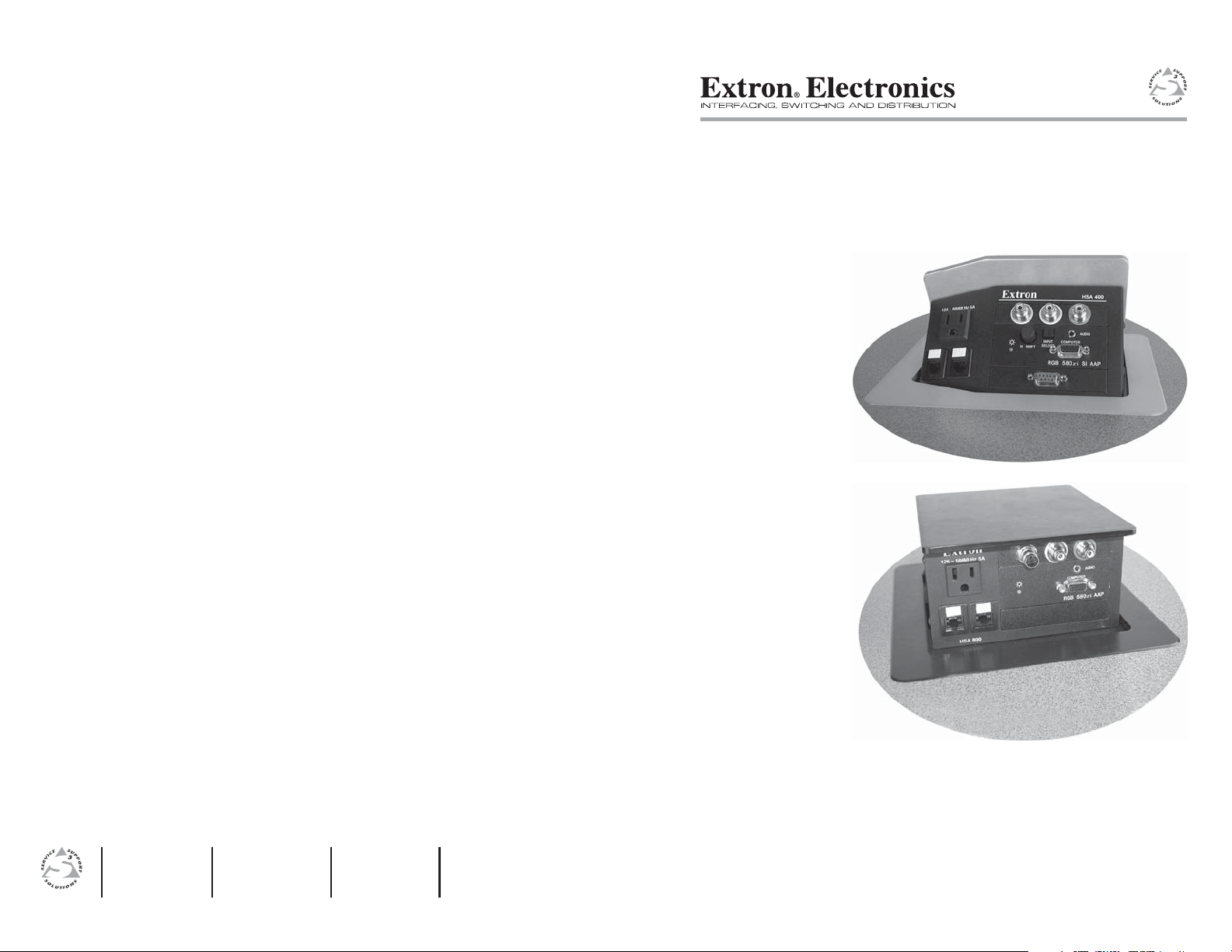
HSA 400, 402, 452 Installation
Introduction
The Extron HSA 400, HSA 402, and HSA 452 ship with Category
(CAT) 6 cables terminated with RJ-45 connectors between the
front panel and lower enclosure bezel plug-ins. Some users
prefer a telephone (RJ-11) connector. This conversion kit
consists of a length of telephone cable terminated with RJ-11
connectors to replace one of the CAT 6/RJ-45 cables.
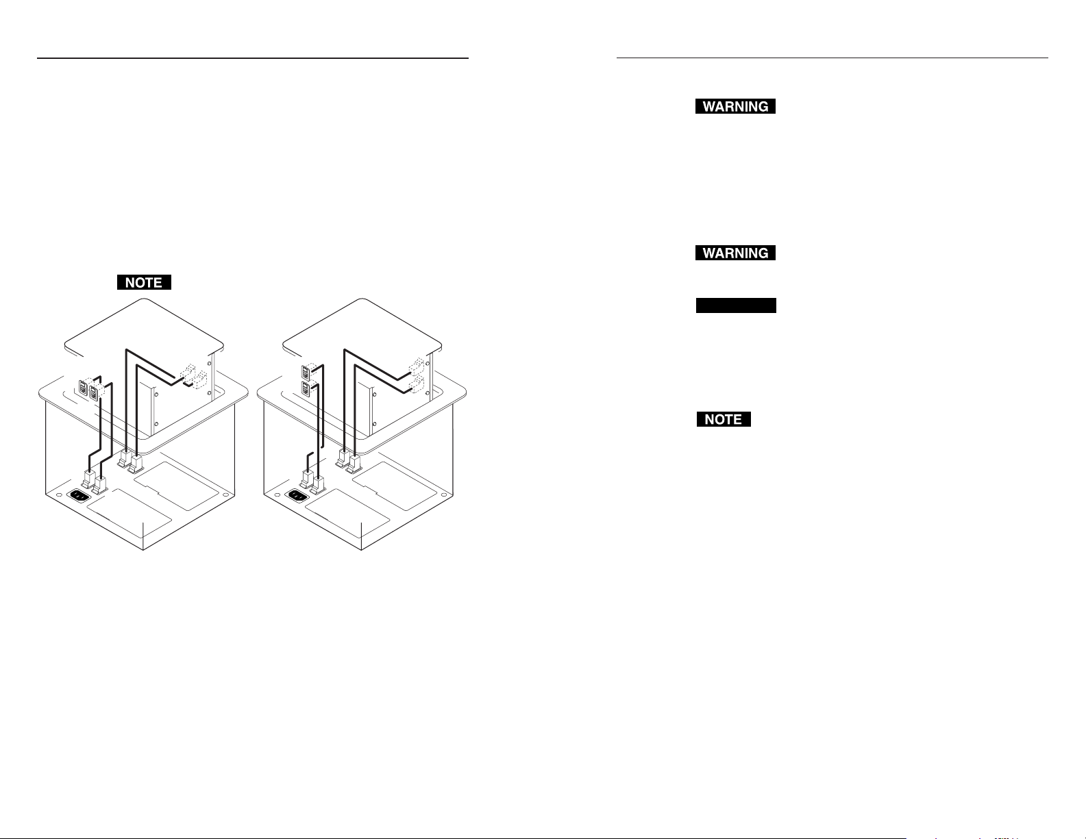
Figure 1-1 shows the location of the bezel plug-ins on the
underside of the lower enclosure for the HSA 402. Figure 1-2
shows the associated connectors on the front panels of the
HSAs. When replacing the CAT 6 cable, match the front panel
connection
B
, and so forth.
A B C D
A
with the underside connector A, match B with
Only connectors A and B are present on the HSA 400.
C
Only connectors
Printed in the USA
08 01
33-673-01 A
50/60 Hz
AC
125V 10A
Fax +81.3.3511.7656
+81.3.3511.7655
Chiyoda-ku, Tokyo 102-0074 Japan
3-9-1 Kudan Minami
Daisan DMJ Bldg. 6F
Extron Electronics, Japan
Fax +31.33.453.4050
+31.33.453.4040
The Netherlands
3821 AH Amersfoort
Beeldschermweg 6C
Extron Electronics, Europe
and D are present on the HSA 452.
Fax +65.383.4664
www.extron.com
+65.383.4400
Singapore 368363
PM Industrial Building,
135 Joo Seng Road, #04-01
Extron Electronics, Asia
Fax 714.491.1517
714.491.1500
USA
Anaheim, CA 92805
1230 South Lewis Street
Extron Electronics, USA
HSA 400/402/800/802
120-240 50/60 Hz 5A
A B
HSA 400
120-240 50/60 Hz 5A 120-240 50/60 Hz 5A
AUDIO
INPUT
COMPUTER
SELECT
H. SHIFT
RGB 580xi SI AAP
HSA 400 HSA 402
COMPUTER
AUDIO
A B C D
INPUT
SELECT
H. SHIFT
RGB 580xi SI AAP
HSA 452
H. SHIFT
HSA 452
C D
INPUT
COMPUTER
SELECT
RGB 580xi SI AAP
AUDIO
Figure 1-2 — Front panel RJ-45 connectors
The edges of the top panel are sharp. Exercise care
when the HSA is removed from the table to prevent
personal injury.
CAUTION
The edges of the top panel are bevelled to an ultrafine thickness of less than 0.04 (4/100)”
(approximately 1 mm). These edges are soft and can
be easily nicked or bent. Exercise caution when
handling and mounting the enclosure.
Mishandling can damage the appearance of the
enclosure.
HSA 402
120-240 50/60 Hz 5A
Figure 1-1 — Lower enclosure underside features
Removing the HSA from the Table
Ensure that AC power is disconnected before
servicing the HSA unit.
1. On the underside of the clamshell and in the enclosure, cut
the tie wraps that route the AAP cables out of the way.
2. Disconnect the IEC power cord and the RJ-45 connectors
from the underside of the surface mount enclosure.
3. Disconnect any cables connected to the existing AAPs at
the ends of the cables away from the HSA.
1-2
RJ-45 to RJ-11 Conversion Kit • HSA 400, 402, 452 Installation
The surfaces of the HSA enclosure have screws and other
protrusions that could damage fine furniture. Do not
rest the enclosure on unprotected furniture.
4. On the underside of the table, remove the two bolts that
secure the clamshell to the HSA (figure 1-3). Lift the
enclosure out of the table. Ensure that the cables
connected to the AAPs do not snag or pull on any
protrusions.
Removing the Front Panel Connector
1 Through the access hole in the rear of the enclosure, cut
the tie wraps that bundle the power and CAT 6 cables.
RJ-45 to RJ-11 Conversion Kit • HSA 400, 402, 452 Installation
1-3
Page 6

HSA 400, 402, 452 Installation, cont’d
125 - 50/60 Hz 5A
H
S
A
4
0
2
H
. S
H
IN
IF
P
T
U
SE
T
LE
C
125 - 50/60 Hz 5A
C
T
A
O
U
M
D
P
U
IO
TE
R
R
G
B
5
8
0
x
i
S
I
A
A
P
HSA 402
Mounting
Surface
AAP Cables
Clamshell
IEC Power Cord
4 RJ-45 Connectors
Flat Washer
Full Thread
Mounting Bolts
Figure 1-3 — Removing the HSA 402 from the table
2. Through the access hole in the rear of the enclosure,
disconnect the 3-prong cable connector on the interior AC
cable (figure 1-4).
3. Open the top panel and remove and retain the four Allen
screws on the right and left sides of the front panel
(figure 1-5). Lift the front panel away from the enclosure
as far as the connected cables allow.
4. With a tweeker, push down on and gently twist on the
front of each RJ-45 connector detent to disconnect the
connector from the rear of the front panel bezel plug-in.
5. Remove the front panel from the enclosure.
Leave the top panel open for the time being.
Ensure that the edges of the front
panel do not scratch the finished
surface of the top panel flange
when removing the panel.
Figure 1-4 — Disconnecting the interior AC cable
Allen screws ea. side.
Remove two
Lift panel out
of enclosure.
12
5
- 5
0
/6
0
H
z 5
A
HSA 400
H
. SH
INPU
IFT
SELEC
T
CO
T
A
U
M
D
PU
IO
TER
RGB 580
xi
SI AAP
Figure 1-5 — Removing the front panel
Replacing the Lower Enclosure Connector
1. Identify the RJ-45 connector to be replaced.
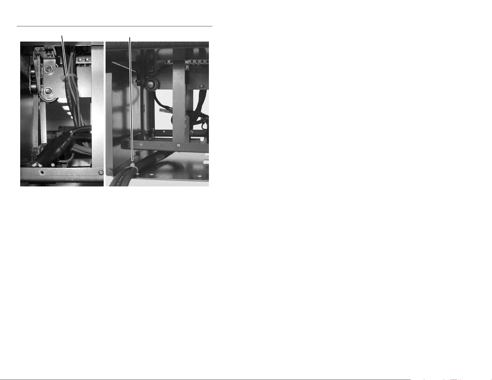
Simultaneously:
a. With a tweeker in one hand, reach through the small
access hole in the front of the enclosure (figure 1-6)
and gently pry outward on the front of the RJ-45
connector detent on the bezel plug-in,
b. While you reach your other hand through the access
hole in the rear of the enclosure and tilt the connector
back.
This disconnects the connector from the interior of the
lower enclosure without damaging the bezel plug-in.
RJ-45 to RJ-11 Conversion Kit • HSA 400, 402, 452 Installation
RJ-45 to RJ-11 Conversion Kit • HSA 400, 402, 452 Installation
1-51-4
Page 7

HSA 400, 402, 452 Installation, cont’d
Tie Wrap
Tie Wrap
Figure 1-6 — Releasing the bezel plug-in detent
2. Reach your hand through the access hole in the rear of the
enclosure and snap the replacement RJ-11 connector onto
the interior of the lower enclosure bezel plug-in.
3. Reconnect the interior AC power cable.
4. Use three tie wraps to bundle the power, CAT 6 and
telephone cables (figure 1-7). Use the impressions on the
retained CAT 6 cable of the tie wraps that you cut in
Removing the Front Panel Connector, step 1 as a guide for tie
wrapping the bundle.
Replacing the Front Panel Connector and Reassembling the HSA
1. Loosely place the front panel in the surface mount
enclosure. Do not secure it in place at this time.
2. Feed the cables connected to the AAPs in the HSA through
the hole in the table and connect them to the devices that
you disconnected them from in Removing the HSA from the
Table, step 3 on page 1-2.
3. Carefully lower the HSA enclosure into the table opening.
From the underside, bolt the clamshell to the enclosure
with the two bolts removed in Removing the HSA from the
Table, step 4 on page 1-3.
4. Connect the IEC power cord, the RJ-11, and RJ-45 cables to
the connectors on the underside of the surface mount
enclosure.
Tie Wrap
Figure 1-7 — Bundling interior cables
5. Open and close the top panel while you experiment with
the routing of the cable bundle. Find a routing that allows
the top panel to open and close smoothly. If desired, use
tie wraps to secure the bundled cables to the tie-down
holes in the lower enclosure or on the mounting frame.
6. Secure the front panel in place with the Allen screws
removed in Removing the Front Panel Connector, step 3 on
page 1-4.
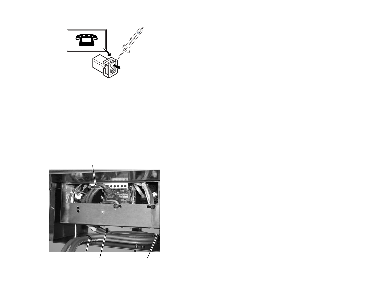
7. If desired, on the front panel, replace the connector icon by
prying the old icon off of the bezel plug-in (figure 1-8)
with a tweeker and snapping a new icon in place.
RJ-45 to RJ-11 Conversion Kit • HSA 400, 402, 452 Installation
RJ-45 to RJ-11 Conversion Kit • HSA 400, 402, 452 Installation
1-71-6
Page 8
HSA 400, 402, 452 Installation, cont’d
Icon Labels
Figure 1-8 — Changing the connector icon
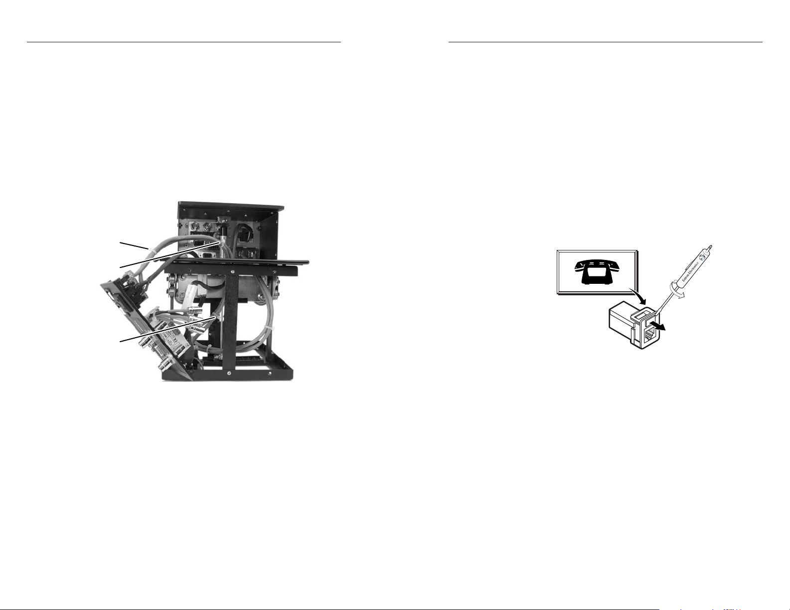
Routing the AAP Cables
1. Open the top panel to extend the AAP cables to their
maximum pull.
2. Experiment with AAP cable positioning to ensure that the
cables do not rub against the edges of the AAP cable hole
and to ensure that the cable pull does not restrict the
movement of the top panel. Figure 1-9 shows the cables
routed to the side, which proved effective in tests at
Extron.
3. Use tie wraps to secure the AAP cables to the tie-down
holes in the clamshell and enclosure.
Secure AAP cables here
Page intentionally left blank
Secure AAP cables here
Secure AAP cables here
Figure 1-9 — HSA 402 AAP cable routing
1-8 1-9
RJ-45 to RJ-11 Conversion Kit • HSA 400, 402, 452 Installation
Secure AAP cables here
RJ-45 to RJ-11 Conversion Kit • HSA 400, 402, 452 Installation
Page 9

HSA 400, 402, 452 Installation, cont’d
Page intentionally left blank
RJ-45 to RJ-11 Conversion Kit
Chapter Two
2
1-10
HSA 800, 802 Installation
Introduction
Removing the HSA from the Table
Replacing the Connectors
Reassembling the HSA
Routing the AAP Cables
RJ-45 to RJ-11 Conversion Kit • HSA 400, 402, 452 Installation
Page 10
HSA 800, 802 Installation
Introduction
The Extron HSA 800 and HSA 802 ship with Category (CAT) 6
cables terminated with RJ-45 connectors between the front
panel(s) and lower enclosure bezel plug-ins. Some users prefer
a telephone (RJ-11) connector. This conversion kit consists of a
length of telephone cable terminated with RJ-11 connectors to
replace one of the CAT 6/RJ-45 cables.
Figure 2-1 shows the location of the bezel plug-ins on the
underside and front panels of all versions of the HSA 802.
When replacing the CAT 6 cable, match front panel connector
A1 with underside connector A1, match A2 with A2, and so
forth.
A1
A2
A1
B2
B1
A2
Connectors B1 and B2 are present on the HSA 802 only.
B2
B1
A2
A1
A1
B1
A2
B1
B2
B2
Removing the HSA from the Table
Ensure that AC power is disconnected before
servicing the HSA unit.
1. On the underside of the clamshell and in the enclosure, cut
the tie wraps that route the AAP cables out of the way.
2. Disconnect the IEC power cord and RJ-45 connectors from
the underside of the surface mount enclosure.
3. Disconnect any cables connected to the existing AAPs at
the ends of the cables away from the HSAs.
The edges of the top panel are sharp. Exercise care
when the HSA is removed from the table to prevent
personal injury.
CAUTION
4. On the underside of the table, remove the two bolts that
secure the clamshell to the surface mount enclosure
(figure 2-2). Lift the enclosure out of the table. Ensure that
the cables connected to the AAPs do not snag or pull on
any protrusions.
The flanged edges of the top of the surface enclosure
are bevelled to an ultra-fine thickness of less than
0.04 (4/100)” (approximately 1 mm). These edges
are soft and can be easily nicked or bent. Exercise
caution when handling and mounting the
enclosure. Mishandling can damage the appearance
of the enclosure.
The surfaces of the HSA enclosure have screws and other
protruding hardware that could damage fine furniture.
Do not rest the enclosure on unprotected furniture.
2-2
USA and IEC Versions EU, UK, and Australian Versions
Figure 2-1 — Underside and front panel bezel plugins
RJ-45 to RJ-11 Conversion Kit • HSA 800, 802 Installation
RJ-45 to RJ-11 Conversion Kit • HSA 800, 802 Installation
2-3
Page 11

HSA 800, 802 Installation, cont’d
125 - 50/60 Hz 0.5A
I
N
P
U
S
T
E
L
E
C
C
T
O
A
M
U
P
D
U
I
O
T
E
R
Remove 16
screws.
HSA 802
Shroud
Mounting
Surface
Ensure that the edges of the connector panels do not
scratch the finished surface of the top panel flange when
removing the panels.
Remove two
Screws ea. side.
H
S
A
8
00
125 - 50/60 Hz 0.5A
IN
P
U
S
T
E
L
E
C
C
T
O
A
M
U
P
D
U
I
O
T
E
R
Remove panel
from enclosure.
Replacement Face Plate
Screws (4) Under Enclosure
Figure 2-3 — Removing the connector/AAP panel
AAP Cables
Clamshell
IEC Power Cord
RJ-45 Connectors
Flat Washer
Full Thread
Mounting Bolts
Figure 2-2 — Removing the HSA 802 from the table
5. On all connector/AAP panels, remove the four screws on
the right and left sides of the front panel (figure 2-3).
Retain the screws. Lift the panels away from the enclosure
as far as the connected cables allow and then allow the
panels to dangle, supported by their connected cables.
RJ-45 to RJ-11 Conversion Kit • HSA 800, 802 Installation
Replacing the Connectors
1. Remove and retain the four screws in the corners of each
side surface of the enclosure “cube”. Remove the two
halves of the shroud.
Do not remove the screws in the center of each side.
They do not secure the shroud in any way; rather, they
provide structural support to the enclosure.
2. Cut the tie wraps that bundle the CAT 6 cable to be
replaced.
3. Inside the front panel, identify the RJ-45 connector to be
replaced. With a tweeker, push down on and gently twist
on the front of the RJ-45 connector detent to disconnect the
connector from the rear of the front panel bezel plug-in.
4. Inside the bottom frame, identify the RJ-45
connector to be replaced. With a tweeker,
push down on and gently twist on the front of
the RJ-45 connector detent to disconnect the
connector from the bottom frame bezel plugin.
5. Note how the disconnected CAT 6 cable is routed inside
the HSA and then gently pull the cable free.
RJ-45 to RJ-11 Conversion Kit • HSA 800, 802 Installation
2-52-4
Page 12
HSA 800, 802 Installation, cont’d
Icon Labels
6. Route the conversion kit telephone cable in the same
fashion as the removed CAT 6 cable.
7. Snap the replacement RJ-11 connectors on the conversion
kit cable onto the interior of the front panel and lower
frame bezel plug-ins.
Reassembling the HSA
1. Use tie wraps to bundle the CAT 6 and telephone cables
(figure 2-4). Use the impressions on the remaining CAT 6
cable of the tie wraps that you cut in Replacing the
connectors, step 2 on page 2-5 as a guide for placing the tie
wraps.
Tie Wrap
Tie Wrap
Tie Wrap
6. Feed the cables connected to the AAPs in the HSA through
the hole in the table and connect them to the devices that
you disconnected them from in Removing the HSA from the
Table, step 3 on page 2-3.
7. Carefully lower the HSA enclosure into the table opening.
From the underside, bolt the clamshell to the enclosure
with the two bolts removed in Removing the HSA from the
Table, step 4 on page 2-3.
8. Connect the IEC power cord, the RJ-11, and RJ-45 cables to
the connectors on the underside of the surface mount
enclosure.
9. If desired, on the front panel, replace the connector icon by
prying the old icon off of the bezel plug-in (figure 2-5)
with a tweeker and snapping a new icon in place. If
needed, four spare screws are stored in the underside of
the enclosure.
2-6
Figure 2-4 — Bundling interior cables
2. Rest the front panels in place in the enclosure. Do not
secure the panels in place at this time.
3. Open and close the top panel while you experiment with
the routing of the cable bundle. Find a routing that allows
the top panel to open and close smoothly. If desired, use
tie wraps to secure the bundled cables to the tie-down
holes in the lower enclosure or on the mounting frame.
4. Secure the two shroud halves to the enclosure frame with
the eight screws (four per side) removed in Replacing the
Connectors, step 1 on page 2-5.
5. Replace the front panels in the surface mount enclosure
and secure them in place with the screws removed in
Removing the HSA from the Table, step 5 on page 2-4.
RJ-45 to RJ-11 Conversion Kit • HSA 800, 802 Installation
Figure 2-5 — Changing the connector icon
10. Open and close the top panel to check that the cables do
not interfere with smooth operation or rub against sharp
edges. If necessary, reach the cables through the cable
access holed in the lower frame and experiment with the
routing of the cable bundles. If desired, secure the cable
bundles on the mounting frame with tie wraps.
Routing the AAP Cables
1. Open the top panel to extend the AAP cables to their
maximum pull.
2. Experiment with AAP cable positioning to ensure that the
cables do not rub against the edges of the AAP cable hole
and to ensure that the cable pull does not restrict the
movement of the top panel. Figure 2-6 shows the cables
routed to the side, which proved effective in tests at
Extron.
RJ-45 to RJ-11 Conversion Kit • HSA 800, 802 Installation
2-7
Page 13
HSA 800, 802 Installation, cont’d
Secure AAP cables here
View A View B
Secure AAP cables here
Figure 2-6 — HSA 802 AAP cable routing
3. Use tie wraps to secure the AAP cables to the tie-down
holes in the clamshell and enclosure.
2-8
RJ-45 to RJ-11 Conversion Kit • HSA 800, 802 Installation
 Loading...