

Page 1
User’s Manual
RGB 300
Universal Digital Interface
Page 2

Contents Contents
Introduction to RGB 300 Features
Quick Setup and Installation Check
RGB 300 Features ...............................................................................1-1
LCD Menu Driven Controls ................................................... 1-1
Auto-Select and Memory Blocks ...........................................1-2
Level Control (picture) ...........................................................1-2
Peaking Control (sharpness) ...............................................................1-2
Horizontal Shift Control (centering) .......................................1-2
Vertical Shift Control (centering) ...........................................1-2
Automatic Sync Output Selection ..........................................1-2
Automatic Sync Stripping ......................................................1-2
Security Lockout ....................................................................1-2
Auto-switching Power Supply ................................................1-3
RS 232 Control Interface for Remote Control ....................... 1-3
Front Panel Controls ............................................................................1-4
Menu button .......................................................................... 1-4
Cursor buttons .......................................................................1-4
Select button ......................................................................... 1-4
LCD Display .......................................................................... 1-4
Before Installing the Extron RGB 300 ..................................................2-1
Quick Setup Procedure (rear panel, cables)........................................2-1
Installation Check ................................................................................ 2-2
Memory Block Preset Configurations .................................................. 2-3
RS 232 interface specifications ........................................................... 2-4
Power Supply .......................................................................................2-4
Application Diagram.............................................................................2-4
Front Panel Procedures
Auto-Select Function ........................................................................... 3-1
The Three Default Menus .................................................................... 3-1
Front Panel Operation ..........................................................................3-2
Load a Configured Memory Block .........................................3-2
Adjust Current Settings ......................................................... 3-3
Save Settings ........................................................................3-3
Change Sync Settings ...........................................................3-4
Memory Block Preset Configurations .................................................. 3-5
LCD Menu Descriptions
RGB 300 Menu Sequence ...................................................................4-1
Editing the ID Screen ...........................................................................4-2
Loading a Configured Memory Block ....................................4-2
Changing the Menu Language ............................................................ 4-2
Locking/Unlocking The Front Panel .....................................................4-3
Image Adjustment Menus ....................................................................4-3
Level (picture) Control Menu .................................................4-3
Peaking (sharpness) Control Menu .......................................4-3
Horizontal Shift (centering) Menu ..........................................4-4
Vertical Shift (centering) control Menu. .................................4-4
Extron RGB 300 Universal Interface • User’s Manual Extron RGB 300 Universal Interface • User’s Manual
i
Page 3

Contents Contents
Sync Menus .........................................................................................4-4
Sync On (green) Menu ..........................................................4-4
Sync Options .........................................................................4-5
Sync Output Menu.................................................................4-5
Sync Option Menus ...............................................................4-5
Serrations Menu (for Sync On Green, or Comp. Options) .....4-5
Original Sync Menu (for all three sync choices) ....................4-6
Negative Sync Only Menu (for Separate H & V)....................4-6
Centering Options Menus ..................................................... 4-6
Save Menus .......................................................................... 4-6
Naming Memory Blocks .......................................................................4-6
Using Windows® Control Panel Software
Installing the RGB 300 Software..........................................................5-1
Starting the Software ...........................................................................5-1
Using the RGB 300 Control Panel Window .........................................5-2
Remote/Local Mode ..............................................................5-2
Scan Rate Display .................................................................5-2
Horizontal and Vertical Shift .................................................. 5-2
Fade In/Fade Out ..................................................................5-2
Using the Utility Menu ..........................................................................5-3
Using the File Menu .............................................................................5-3
Load from a Memory block ....................................................5-3
Save to Memory Block .......................................................... 5-3
Save All Memory Blocks To Disk ...........................................5-4
Restore All Memory Blocks From Disk ..................................5-4
Exit ........................................................................................ 5-4
Appendix A - Programmer's Guide
Communication Format ...................................................................... A-1
Checksum ........................................................................................... A-2
Disabling Checksum Feature .............................................................. A-3
Host Initiated Communication (CMDn) ............................................... A-4
RGB 300 Initiated Communication (RPRTn) ...................................... A-4
Timing, RS-232 Connector Pin-outs .................................... A-4
Command List .................................................................................... A-5
Reports ................................................................................. A-5
Communications Control ...................................................... A-5
Binary/hex/decimal Conversion Table ................................................. A-6
Using Commands ............................................................................... A-7
CMD0 (30) - Report Scan Rate ............................................ A-7
CMD1 (31) - Report Contents of ID Screen ......................... A-8
CMD2 (32) Report RGB Code (video input detector) ........... A-9
CMD3 (33) - Report Programmed Sync Code ................... A-10
CMD4 (34) - Report Software Version ................................ A-10
CMD5 (35) - Report Actual Sync Code .............................. A-11
CMD6 (36) - Report Video Level ........................................ A-11
CMD7 (37) - Set Video Level .............................................. A-12
CMD8 (38) - Report Horizontal Shift .................................. A-12
CMD9 (39) - Set Horizontal Shift ........................................ A-13
CMD10 (3A) - Report Vertical Shift .................................... A-13
CMD11 (3B) - Set Vertical Shift .......................................... A-14
CMD12 (3C) - Report Peaking Level.................................. A-14
CMD13 (3D) - Set Peaking Level ....................................... A-14
CMD14 (3E) - Report Menu Language .............................. A-15
CMD15 (3F) - Set Menu Language .................................... A-15
CMD16 (40) - Report Current Block Number ..................... A-15
CMD17 (41) - Select New Block Number ........................... A-16
Video Fade Mode ............................................................................. A-16
CMD18 (42) - Report Fade to Black Status........................ A-16
CMD19 (43) - Set the Video Fade Status ........................... A-16
CMD20 (44) - Report Keyboard Lock Status...................... A-17
CMD21 (45) - Set Keyboard Lock Status ........................... A-17
CMD22 (46) - Program ID Screen ...................................... A-18
CMD23 (47) - Save Current In Memory Block.................... A-18
CMD24 (48) - Read Name Of Memory Block ..................... A-19
RPRT0 (70) - Signal Change ............................................. A-20
RPRT1 (71) - New Block Selected ..................................... A-20
RPRT2 (72) - Entered Menu Mode (local).......................... A-20
RPRT3 (73) - Exited Menu Mode (remote mode) .............. A-20
Appendix B - Reference Material
RGB 300 Specifications ...................................................................... B-1
Warranty ............................................................................................. B-2
RGB 300 User's Manual
68-149-01
Rev. A-1
69-06
Rev. B
79-04
New style format
ii iii
Extron RGB 300 Universal Interface • User’s Manual Extron RGB 300 Universal Interface • User’s Manual
Page 4

RGB 300 Digital Universal Interface
User's manual
Chapter One
Introduction to RGB 300 Features
LCD Menu Driven Control
Auto-Select and Memory Blocks
Image Display Controls
Automatic Sync Output Selection
Security Lockout
1
RS 232 Control Interface
Front Panel Controls
Page 5
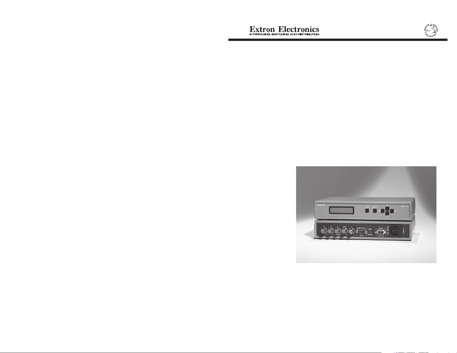
The Extron RGB 300 is a digitally controlled Universal Analog/
ECL Computer-Video Interface. It can connect most any
computer to a video presentation device, such as a large
screen projector or data monitor. The RGB 300’s built-in
intelligence automatically selects sync settings and other
parameters for quick, easy setup.
RGB 300 Features
The RGB 300 features allow video output to be controlled in
several ways:
Chapter 1 • Introduction to RGB 300 Chapter 1 • Introduction to RGB 300
Level Control (picture)
This feature is similar to a contrast control on a data monitor,
which is used to adjust the intensity of the video level on the
projector/monitor screen. There are 255 levels for this
Control.
Peaking Control (sharpness)
This control is similar to a sharpness control on a data
monitor. It is also used to compensate for long cable runs.
There are eight Peaking levels.
· Automatic detection and setup for quick installation
· Custom setup and adjustments made from the Front Panel
· RGB 300 Windowsâ software, through an RS-232 interface
· User-written programs, through the RS-232
LCD Menu Driven Controls
The RGB 300 does not have “knobs” or “switches” to control
its operation. Instead, the “controls” are displayed and
adjusted using the Front Panel LCD display and six buttons.
The Front Panel can be used in any of four languages:
English, French, Spanish and German. The display has two
main functions:
1. The RGB 300 automatically detects and displays vital
troubleshooting information, such as the presence of Red,
Green and Blue video input signals, as well as the horizontal
and vertical scan frequencies.
2. The user can step through, and display any of the controls or
features in the interface.
___ Chapter 3 has details on using the Front Panel.
Auto-Select and Memory Blocks
There are 25 memory blocks for storing video format
information, such as video and sync and control settings.
Each block represents one video format configuration (e.g.
memory block #06 = VESA3, or #10 = MAC16”, etc.). Extron
has pre-loaded several memory blocks with configurations
that match most video requirements. The RGB 300
automatically loads the first memory block that most closely
matches the computer’s video output.
Horizontal Shift Control (centering)
This feature shifts the displayed image to the left or right on
the projector/monitor screen. There are 255 positions for this
control.
Vertical Shift Control (centering)
This feature shifts the displayed image up or down on the
projector/monitor screen. There are 255 positions for this
control.
Automatic Sync Output Selection
The RGB 300 automatically detects which cables are
connected, and sends the Sync On Green, Composite, or
Separate Horizontal and Vertical sync signals to the correct
output cables. This function can be overridden through menu
controls.
Automatic Sync Stripping
The RGB 300 automatically strips all incoming sync from the
red, green, and blue channels for clean, crisp signal
processing. Sync may be recombined with the green channel
if necessary.
Security Lockout
Built into the RGB 300 is a universal passcode which allows
the user to “lock out” the front panel controls after setup. This
feature makes it impossible to change the controls after setup.
Auto-switching Power Supply
The RGB 300 is equipped with an internal auto-switching
power supply that operates from any input voltage in the 90 to
270 VAC, 50/60 Hz. range. No equipment changes are
necessary.
RS-232 Control Interface for Remote Control
The RGB 300 has a built-in RS-232 interface to allow the unit
to be controlled remotely, in either of two ways:
1. Use the Windows
provided by Extron. Benefite are listed below.
RGB 300 Control Panel software
1-1
Extron RGB 300 Universal Interface • User’s Manual Extron RGB 300 Universal Interface • User’s Manual
1-2
Page 6
2. The user may write software to control the RGB 300 from a
PC, or other system. See the Programmer’s Guide is in
Appendix A.
The RS-232 protocol is fixed at 9600 baud, no parity, 8 data
bits and 1 stop bit.
Benefits of Windows® RGB 300 software
Using the Windows® software provided with the RGB 300
adds several advantages over Front Panel operation.
All of the controls are quicker and easier to use with the onscreen control panel.
Application setups can be stored as disk files, therefore an
unlimited number of setups can be stored and reloaded from
the PC's hard drive or floppy disk.
See Chapter 5 for details on using this software.
Chapter 1 • Introduction to RGB 300 Chapter 1 • Introduction to RGB 300
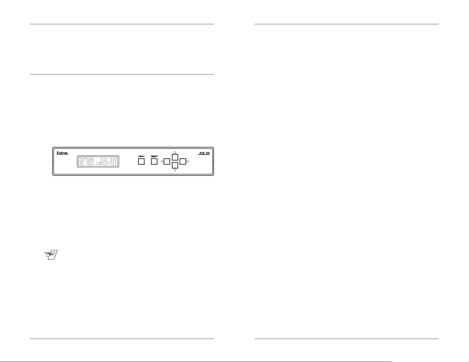
Front Panel Controls
The Front Panel LCD display is normally in a 3-menu default
cycle, displaying important video input information:
· The Red, Green and Blue video input signals detected
· The Video Format currently being used
· The horizontal and vertical scan frequencies
The Front Panel buttons have many functions, depending on
what the panel is being used for at any particular time. For
example, the user can display, and adjust any controls or
switches to adjust the video display. The specific functions for
these buttons are described in later procedures. General
descriptions follow.
___ There is a built in time-out function which will return back to the
default menus if no buttons are pressed for 20 seconds. If a
mistake was made, this is a convenient way out.
1-3
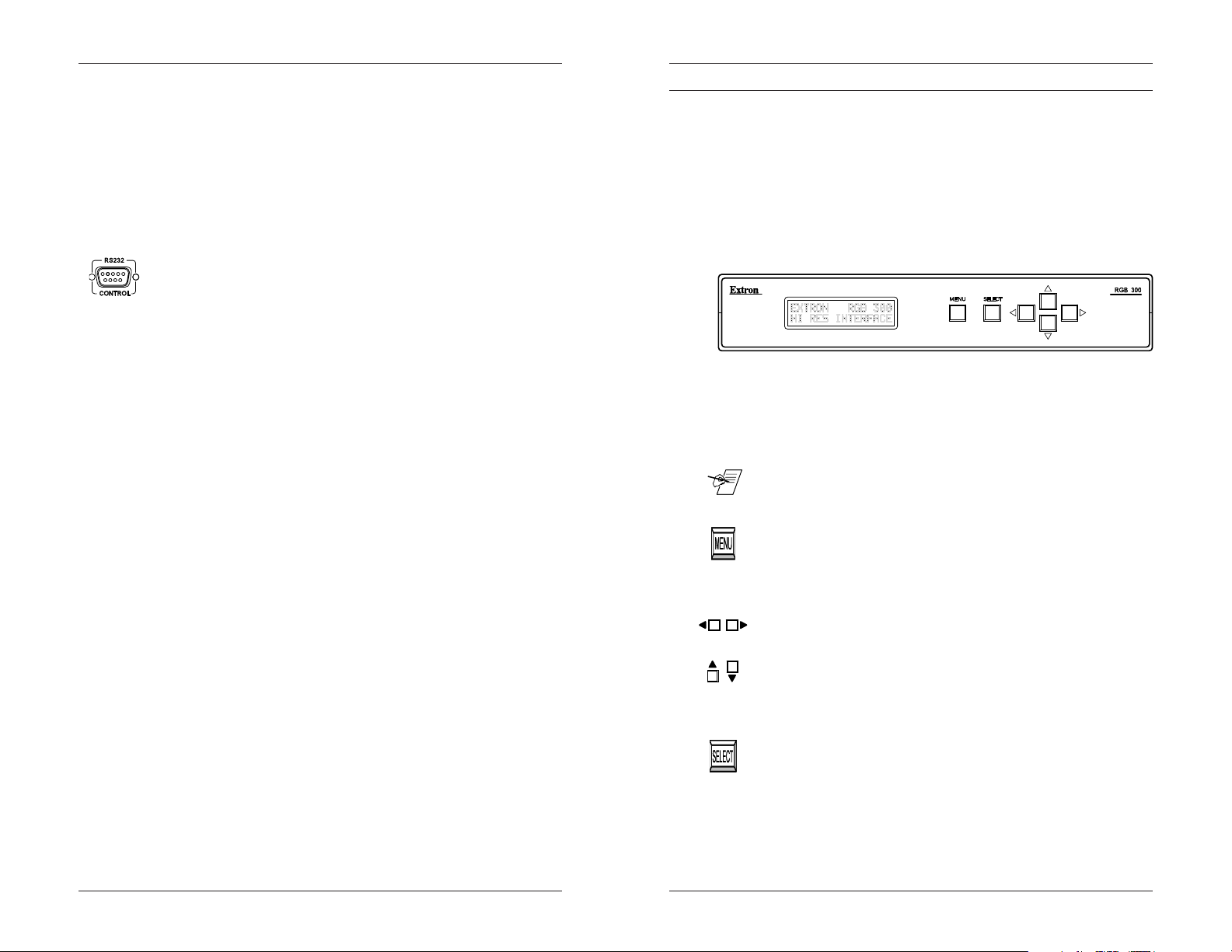
Menu button
The Menu button is used to break out of the default mode and
step through the menus, to view or change the operation.
Repeated pressing will loop back to the default menus.
Cursor buttons
The cursor buttons are typically used to step through the
options, before making a choice. These options could be
alpha characters, numeric settings, load choices, etc. The
user may want to change the value of the current setting. (i.e.
increase or decrease level, horizontal, shift, peaking etc.)
These buttons will also toggle the sync options on and off.
Select button
The Select button is used to break out of the default mode
and often used to choose the setting, or condition that is
currently being displayed in the LCD window.
LCD Display
While using the front panel, the LCD display provides helpful
information, such as which buttons to use for choices.
Extron RGB 300 Universal Interface • User’s Manual Extron RGB 300 Universal Interface • User’s Manual
1-4
Page 7

RGB 300 Specifications
Part Number ..60-148-01
User's Manual ..68-149-01
Dimensions ..9.75" W x 7.0" D x 1.75" H
Power Supply ..115/230 volt, auto-switchable, internal
Video:
Sync:
Output Signal:
Frequency Compatability:
RGB Video ..Bandwidth 220 MHz (2nS rise time)
Chapter 1 • Introduction to RGB 300 Chapter 1 • Introduction to RGB 300
Weight ..2 lb, 8 oz
Analog ..0.35 to 1.2 volts, peak-to-peak
ECL .. 0.8 to 1 volt, peak-to-peak
.. Separate H & V Sync TTL (±)
.. Composite H & V TTL (±)
.. Sync on Green TTL (±)
.. Sync on Red, Green & Blue TTL (±)
Video ..Analog 0.3 to 1 volt peak-to-peak (variable)
Sync ..Sync on Green (-)
.. Composite Sync (-)
.. Separate H & V (±)
Horizontal ..15 - 125 kHz (automatically)
Vertical ..30 - 170 Hz (automatically)
RGB 300 Digital Universal Interface
User's manual
LCD Scan Rate Range:
Horizontal ..15 - 150 kHz
Vertical ..30 - 150 Hz
LCD Menu (Front Panel):
.. Back-lit alpha-numeric display
.. (English, German, Spanish or French)
Warranty:Two years, parts and labor
Extron RGB 300 Universal Interface • User’s Manual Extron RGB 300 Universal Interface • User’s Manual1-5
Chapter Two
Quick Setup and Installation Check
Before Installing
Quick Setup Procedure
Rear Panel Cables
Installation Check
Memory Block Preset Configurations
2
RS-232 Specifications
Page 8
Before Installing the Extron RGB 300
____ Do not connect the power cord until instructed to do so in the
following installation procedure. There is no power switch.
For quick, automatic setup, use the following Basic
Installation steps. The RGB 300 will detect the scan rate
from the computer and automatically load a video format from
a preset memory block. For most applications, the installation
should be complete. The Front Panel may be used later for
custom installation, or to make changes after completion of
the basic installation.
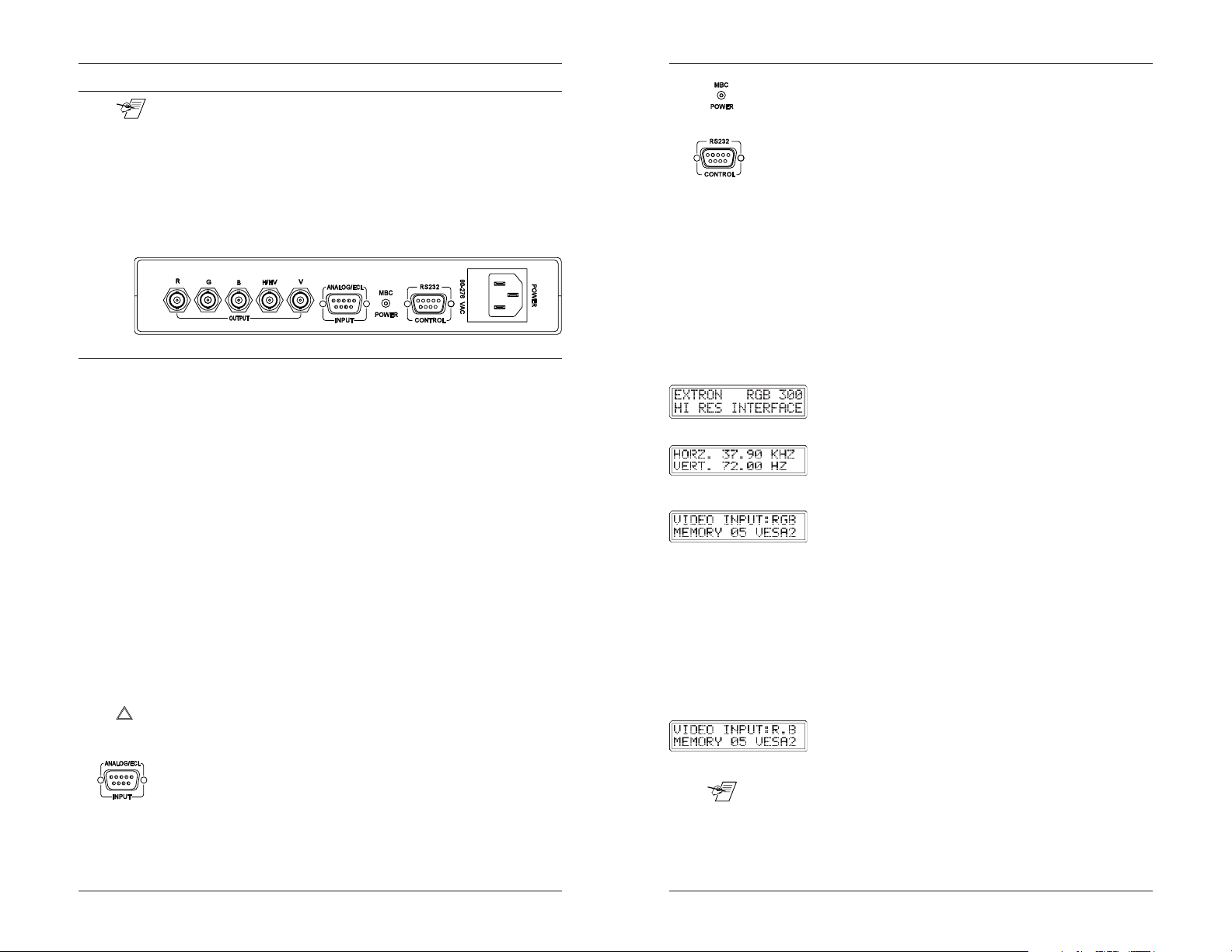
Quick Setup Procedure (rear panel cables)
1. Turn Computer and Monitor Power OFF
Do not connect the RGB 300 Power Cable yet. (There is no
power switch.)
2. Disconnect the Local Computer Monitor Video Cable.
3. Connect BNC Output Cables to the Data Monitor/Projector All BNC outputs are RGB analog. The BNC connectors are
marked R, B, G, H/V and V. They may be connected any of
three ways:
• Red, Green/sync and Blue, for RGB with sync on green.
(3-cable hook up)
• Red, Green, Blue and H/HV, for RGB with composite
Horizontal and Vertical Sync signals. (4-cable hook up)
• Red, Green, Blue, H/HV and V, for RGB with separate
Horizontal and Vertical Sync signals. (5-cable hook up)
The Extron RGB 300 automatically detects which cables are
connected and sends sync signals to the correct output.
______ The output cables must have 75 W termination at the Data
Monitor/ Projector; if not, the automatic setup may not work.
Look for a switch on the Data Monitor.
4. Connect the MBC video cable from the computer (Power
PC, PC, Mac or workstation) to this Analog/ECL Input
connector, and to the Local Monitor.
Chapter 2 • Quick Setup and Installation CheckChapter 2 • Quick Setup and Installation Check
5. RS-232 Control (optional) -If using a PC, or other system to
7. Observe that the RGB 300 LCD display lights up, and cycles
Installation Check
To be sure the installation is complete, do the following:
1. Check that the LCD default menus show the correct
If, for example, green input is missing, the RGB display would
show the “G” missing. For this example, the second line
____ The memory block that is loaded automatically is the first
match the RGB 300 finds. If there is a specialized block with a
higher block number, it may not load automatically because the
scan for a match begins with block #1.
4a. MBC Power Connector If the Analog/ECL, MBC video
cable has a small, phono jack attached to it, plug it into
this female connector.
program the RGB 300, connect the cable here. (pin-outs
and interface specifications are given under Installation
Check, after this procedure.)
6a. Turn Power ON for the Computer supplying the video
input. - (Power PC, PC, Mac or workstation)
6b. Turn Power ON for the Data Monitor/Projector.
6c. Connect power to the RGB 300.
through three default menus.
7a. The ID, or Title Menu - Displays the name of the unit.
To change this display, see the
in Chapter 3.
7b. The Scan Rate Menu - From the monitor breakout cable,
the RGB 300 detects the scan rate frequencies and
displays them. This is an example.
7c. The Video Input Menu - If the RGB 300 has detected
Red, Green & Blue inputs, the first line displays the
letters RGB. The second line displays the Memory Block
# and video format that was loaded, either manually or
automatically. This is an example.
information. (as described in Step 7, above). Use the menus
as a troubleshooting aide.
shows the RGB 300 is using settings stored in Memory
05, which is preset for a VESA2. Check to be sure the
correct block was loaded. (See Memory Block table.)
Editing The ID Screen
,
2-1 2-2
Extron RGB 300 Universal Interface • User’s Manual Extron RGB 300 Universal Interface • User’s Manual
Page 9
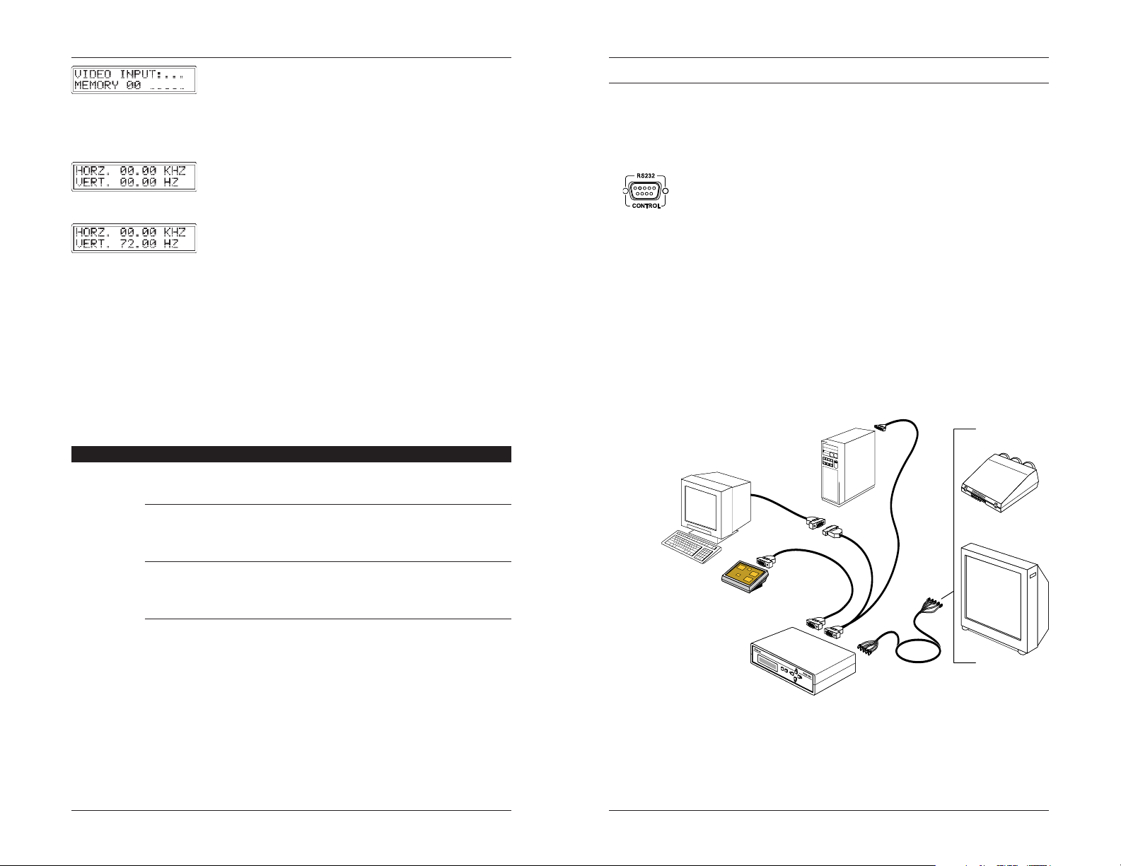
If no video input was detected, no memory block was
loaded, and the display will show spaces.
The scan rate menu may be used for troubleshooting as
follows:
The timing for the RGB 300 is derived from the vertical sync
signal. If the vertical sync signal is not present, both
the vertical and horizontal frequencies will be zeros,
even if there is a horizontal signal present.
If a vertical sync signal is detected, and the horizontal
sync is not detected, the vertical frequency is
displayed, but the horizontal frequency is zeros.
2. Recheck the Basic Installation steps for correct cable
connections, etc.
3. Fourteen memory blocks have been loaded with preset
video formats to match most computers. Check the following
memory preset table to see if the format specifications
match those required by the computer video signal.
Memory Block Preset Configurations
The following table shows the memory blocks that are preloaded with video scan formats.
Chapter 2 • Quick Setup and Installation CheckChapter 2 • Quick Setup and Installation Check
RS-232 interface specifications
9600 baud, no parity, 8 data bits and 1 stop bit.
RS-232 Connector Pins are as follows:
Pin
1 N/C (not connected)
Pin 2 TD Transmit Data (data out of the RGB 300)
Pin 3 RD Receive Data (data into the RGB 300)
Pin 4 N/C
Pin 5 Ground
Pin 6 N/C
Pin 7 Reserved
Pin 8 N/C
N/C
Pin 9
Power Supply
The RGB 300 is equipped with an internal auto-switching
power supply that operates from any input voltage in the 90 to
270 VAC, 50/60 Hz range. No equipment changes are
necessary. The fuse should only be a 250V 0.5A Slo-Blo type.
Application Diagram
The diagram below shows possible uses for the RGB 300.
2-3
Mem # Format Pixel x Line Hor. kHz Ver. Hz
01 VGA1 640 x 350 31.5 70
02 VGA2 640 x 400 31.5 70
03 VGA3 640 x 480 31.5 60
04 VESA1 800 x 600 35.2 56
05 VESA2 640 x 480 37.9 72
06 VESA3 1024 x 768 48.4 60
07 VESA4 1024 x 768 56.4 70
08 Mac 12” 512 x 384 24.5 60
09 Mac 13” 640 x 480 35.0 60
10 Mac 16” 832 x 624 49.7 75
11 Mac 21” 1152 x 870 68.7 75
12 Sun1 1152 x 900 71.7 76
13 Sun2 1280 x 1024 81.0 76
14 SGI 1280 x 1024 63.9 60
If adjustments are required, go to Chapter 3 for custom
installation, to view settings, adjust the current settings, or
load a different memory block.
Chapter 5 describes how to use the Windows® RGB 300
Control Panel to do the same functions.
Extron RGB 300 Universal Interface • User’s Manual Extron RGB 300 Universal Interface • User’s Manual
Local Monitor
Control System
RGB 300
Power PC, Mac
Or Workstation
Large Screen
Data Projector
Or
Data Monitor
2-4
Page 10
____
Chapter 2 • Quick Setup and Installation CheckChapter 2 • Quick Setup and Installation Check
RGB 300 Digital Universal Interface
User's manual
2-5
Chapter Three
Front Panel Procedures
Making Image Adjustments
3
Saving New Settings to Memory
Extron RGB 300 Universal Interface • User’s Manual Extron RGB 300 Universal Interface • User’s Manual
Auto-Select Function
Three Default Menus
Loading a Memory Block
Changing Sync Settings
Page 11

Chapter 3 • RGB 300 Front Panel Procedures Chapter 3 • RGB 300 Front Panel Procedures
____ This chapter give procedures for setting up the RGB 300. For
the over-all picture, as well as details about each menu, see
Chapter 4.
Auto-Select Function
The Auto-Select function takes place on power up, as well as
any time the input scan rate changes. Auto-Select searches
all the saved memory blocks for a scan rate match. When a
match is found, all the settings from that memory block are
automatically loaded. If the input scan rate is within ± 5% of a
configuration stored in a memory block, is considered to be a
“match”. If no match is found then no changes in the settings
take place. (It keeps the last configuration.)
In most installations, the Auto-Select feature takes care of the
setup. If changes in settings are necessary, use the
procedure and descriptions that follow. If the installation uses
a PC with Windows, see Chapter 5 to install and use this
software.
The Three Default Menus
____ These three menus are also described in Chapter 2,
Installation Check. Refer to that section if the displays are
suspected to be incorrect.
When the RGB 300 is not in menu mode, it is considered to
be in the default mode. In this mode the LCD displays 3
default menus for about 2 seconds each.
The first menu is the ID screen, and is factory
programmed as shown here. To change this menu, see
Editing the ID screen, in Chapter 4.
The second menu displays the scan rate detected from
the video input. See example here.
The third menu shows that RGB input signals are
present, and which memory block and video format is
being used.
This 3-menu default cycle can be broken by pressing either
Select, or Menu keys. The RGB 300 will go from “default”
mode to “menu” mode. If using the Windows RGB 300
software, the unit is “busy” to the software when it is in “menu”
mode.
To stop on any one of the three default menus, press
+ + and Select simultaneously, when the desired menu
appears. When stopped, use the
three menus manually. This action does not affect other
RGB 300 functions. Press
return to the 3-menu cycle.
+
keys to step through the
+ + and Select again to
Front Panel Operation
The RGB 300 “controls” are accessed through the Front
Panel. Use the LCD display, together with front panel keys to
view, or make changes to the current settings. Observe the
monitor or projector screen while making adjustments. The
menu flow chart on page 3-5 may be used as a guide, while
stepping through the menus.
_____ When using the panel, a pause of 20 seconds causes the
RGB 300 to return to the 3-menu default cycle.
The Front Panel may be used to customize the installation in
the following ways:
1. Select and load a preset memory block. (Table on page 3-4.)
2. Make adjustments and save the changes by overwriting the
current memory block. (Procedure in this chapter.)
3. Make adjustments and save them in a new memory block,
with a new name. (Procedure in this chapter.)
4. Make temporary adjustments that will go away when power
is removed. (See Chapter 4.)
5. Make adjustments that remain in local storage when power
is removed. (See Chapter 4.)
Example steps follow. Each menu is described in Chapter 4.
Load a Configured Memory Block
See Memory Block table, page 3-4, for the configuration
choices.
1. From the 3-menu default cycle, press Select to view
the first memory block.
2. Use the
blocks; press
display.
4. Observe that the RGB 300 goes back to the 3-menu cycle,
this time displaying the new memory block
or cursor keys to step through the preset
3. When the desired memory block appears, press
Select to load it. (For this example, block #5.)
5. Check for correct Data Monitor/Projector operation.
or to backup. Empty blocks will not
3-1
Extron RGB 300 Universal Interface • User’s Manual Extron RGB 300 Universal Interface • User’s Manual
3-2
Page 12

Chapter 3 • RGB 300 Front Panel Procedures Chapter 3 • RGB 300 Front Panel Procedures
Adjust Current Settings
1. From the 3-menu display cycle, press Menu to step through,
and view the following control menus. Use the cursor keys
(
) to change the setting. These are only
examples:
2. Level Control - Use Cursor keys to change, and
Menu to accept and go on.
3. Peaking Control - Use Cursor keys to change, and
Menu to accept and go on.
4. Horizontal Shift Control - Use Cursor keys to change,
and Menu to accept and go on.
5. Vertical Shift Control - Use Cursor keys to change,
and Menu to accept and go on.
____ If the image does not move when the shift control is changed,
centering options may have been turned Off, or the unit has
been set to the Original Sync mode. See Sync Option Menus
to change this condition.
This menu could read: Sync On Green, Sync On Comp, or
Sync On Sep. H&V, depending on the setup. Press
Menu to continue on to save menus (path 6-8a), or
press Select to go to sync menus (path 6-10b).
Save Settings
____ This menu will not appear if an input scan rate was not
detected.
6-a. There are two paths to choose from:
Menu will exit to default menus, without saving.
Select goes to the save menus. (7-a)
7-a. Use the cursor keys to step to the memory block
number where the new settings are to be saved. Use cursor
keys to make changes, and then press Select to continue.
If the block is already used, the new settings will overwrite the old ones.
Change Sync Settings
The sync menu chart below is taken from the over-all
flowchart in Chapter 4. It is shown here to illustrate the
relationship between the sync menus.
6-b. Use the cursor keys
7,8-b. The next two menus depend on which sync output is in
9,10-b. These two menus allow the horizontal and vertical shift
and press Select to accept and continue.
S ON G OPTIONS:
SERRATIONS <ON>
S ON G OPTIONS:
ORIG SYNC <ON>
to step through the three output
sync choices. Press Select to choose one, and go to
the next sync option. This path will step through the
sync settings.
effect. Use any Cursor key (
) to switch
between <On> and <Off>. Press Select to accept the
displayed condition and go to steps 9-b and 10-b.
adjustment to be turned <On> or <Off> (allowed or
disallowed). Use any cursor key to change the setting,
Go back to step 6-a (page 3-3) to save new settings
and exit.
3-3
8-a. Use an existing name, or use the cursor keys to scroll
through the alphabet for the character position with the
blinking cursor. Use the
cursor keys to move to
another character position. When finished with the name,
press Select to save and exit to the default menus.
____ The new information is now displayed in the default menus.
Extron RGB 300 Universal Interface • User’s Manual Extron RGB 300 Universal Interface • User’s Manual
3-4
Page 13

____ If cables are not connected, changes cannot be saved.
Memory Block Preset Configurations
Record any new video format configurations in the
appropriate block numbers in the table below.
____ When the RGB 300 scans the memory blocks, it starts with
Mem #1 and loads the first block it sees that matches the video
input. For this reason, a customized block in a higher memory
location may not load automatically. In this case, the user may
have to load it.
Mem# FormatPixel x Line Hor.kHz Ver.Hz
01 VGA1 640 x 350 31.5 70
02 VGA2 640 x 400 31.5 70
03 VGA3 640 x 480 31.5 60
04 VESA1 800 x 600 35.2 56
05 VESA2 640 x 480 37.9 72
06 VESA31024 x 768 48.4 60
07 VESA41024 x 768 56.4 70
08 Mac 12”512 x 384 24.5 60
09 Mac 13”640 x 480 35.0 60
10 Mac 16”832 x 624 49.7 75
11 Mac 21”1152 x 870 68.7 75
12 Sun1 1152 x 900 71.7 76
13 Sun21280 x 1024 81.0 76
14 SGI 1280 x 1024 63.9 60
15
16
17
18
19
20
21
22
23
24
025
Chapter 3 • RGB 300 Front Panel Procedures Chapter 3 • RGB 300 Front Panel Procedures
RGB 300 Digital Universal Interface
User's manual
LCD Menu Descriptions
Menu Sequence Flowchart
Adjustment Menus
Sync Menus
3-5
Save Menus
4
Extron RGB 300 Universal Interface • User’s Manual Extron RGB 300 Universal Interface • User’s Manual
Page 14

Chapter 4 • RGB 300 LCD Menu Descriptions Chapter 4 • RGB 300 LCD Menu Descriptions
RGB 300 Menu Sequence
Chapter 3 gives procedures for setting up specific functions.
This chapter is intended to provide detailed description of all
menus, not necessarily in a sequence. Use the menu
flowchart to locate the menu you want described.
Actual information displayed in the LCD menus will depend on
settings. The individual menus are described on the following
pages.
S ON G OPTIONS:
SERRATIONS <ON>
S ON G OPTIONS:
ORIG SYNC <ON>
_____ Any time the front panel is being used, a pause of 20 seconds
releases the menu mode, and the RGB 300 goes back to the
default cycle, without storing the changes. If the user gets lost
in the menus, or, if a mistake was made, this is the easy way
out. When making temporary adjustments, stop when that
adjustment is complete, and allow the time-out to occur.
Editing the ID Screen
The ID menu is one of the displays in the three-menu default
cycle. The RGB 300 ships with the ID screen as shown here.
However, it can be changed to display any information.
To access the ID screen at any time, press
and Select.
The first character on the ID screen will flash. When entering
text, use the
keys to scroll through the alphabet and
change the character, and then
position, or use
to back up. When the new message is
finished press Select to save it, and return to the 3-menu
cycle. The new information will display in the ID screen.
The other two menus of the default cycle display detected
RGB and scan input signals (see Chapter 3) These two
menus cannot be modified by the user.
Loading a Configured Memory Block
This is described on page 3-2.
Changing the Menu Language
The user may change the menu language by doing the
following: When in the 3-menu default cycle, hold the arrow
key for the desired language and press Select.
and
to go to the next character
4-1
+ Up and Select English
+ Down and Select Spanish
+ Left and Select French
+ Right and Select German
Extron RGB 300 Universal Interface • User’s Manual Extron RGB 300 Universal Interface • User’s Manual
4-2
Page 15

Chapter 4 • RGB 300 LCD Menu Descriptions Chapter 4 • RGB 300 LCD Menu Descriptions
Locking/Unlocking The Front Panel
To lock the front panel press and hold the keys at the
same time, for about 2 seconds, until the display reads as
shown. To unlock the keyboard repeat the procedure until
the display reads as shown to the left.
Note: Once the keyboard is locked it will remain locked even if
the power is removed. To alert the user upon power up if the
keyboard has been locked the unit will show the locked
message
Image Adjustment Menus
The four menus used to adjust the display image are used in
Chapter 3 procedures, and are explained in detail here. The
arrows at each end of these menus remind you which keys to
use to make the adjustment.
Notes: The adjustments made can be in three states:
1. Temporary - lost when power is removed.
2. Temporarily saved - automatically stored when power is
removed.
If adjustments are to be temporarily stored, you must step
through all five menus (Level, Peaking, H-shift, V-shift and
Sync On menus)
3. Permanently saved - Stored by the user in a memory block.
Level (picture) Control menu
The level control is similar to the contrast control on a data
monitor. With this menu the user can change the video level
with the
the level. Pressing the key once changes the setting by 001.
Holding the key for 2 seconds makes the setting change
faster, and holding it longer makes the setting change even
faster. (There are 256 steps for this control.)
When the desired video level is displayed, release the cursor
key and press Menu to go to the next menu, or allow the timeout to occur.
Peaking (sharpness) Control Menu
The Peaking control allows compensation for losses in signal
quality due to cable capacitance. Use this control to adjust the
sharpness of the picture on the presentation screen. Use the
cursor keys to move the indicator to the left or right. Observe
the results on the monitor/projection screen while making the
adjustment. (The Peaking Control has eight possible settings.)
cursor key to lower the level or the key to raise
Horizontal Shift (centering) menu
Use the cursor keys to move the image left and right, while
observing the results on the monitor/projection screen. If no
results, see note 1.
(There are 256 steps for this control.)
When the adjustment is complete, release the cursor key
and press Menu to go to the next menu, or allow the time-
out to occur.
Vertical Shift (centering) control menu.
This control moves the displayed image up and down on the
presentation screen. While observing (see note 1)
screen, use the cursor keys to adjust the vertical centering.
(There are 256 steps for this control.)
When the adjustment is complete, release the cursor key and
press Menu to go to the next menu, or allow the time-out to
occur.
Note 1: If the image does not move when the shift control (horizontal or
vertical) is changed, centering options may have been turned
Off, or the unit has been set to the Original Sync mode. See
Sync Option Menus to change this condition.
Sync Menus
As shown in the menu flowchart, there are three sets of sync
menus, one set for each source. The LCD will display one of
three: Sync On Green (example), Sync On Comp, or Sync On
Sep H&V.
Sync On (green) menu
This menu displays where the sync is being sent and allows
the user to enter the Sync Options menu.
The two choices here are: Select key, if sync options are to
be viewed/changed, or the Menu key to save settings and
exit.
If the Menu key is pressed, one of two things will happen:
a. If there is no signal detected from the video input, the unit
returns to the 3-menu default mode, without allowing
changes to be saved.
b. If a video input signal is present, the RGB 300 displays this
menu:
the video
When the adjustment is complete, release the cursor key and
press Menu to go to the next menu, or allow the time-out to
occur.
4-3 4-4
Extron RGB 300 Universal Interface • User’s Manual Extron RGB 300 Universal Interface • User’s Manual
Page 16

Chapter 4 • RGB 300 LCD Menu Descriptions Chapter 4 • RGB 300 LCD Menu Descriptions
Sync Options
There are three possible menu paths entered through the
Sync On xxxx menu. Each path goes through five menus
related to sync option switches. The Select key is used to
step through the menus, while the cursor keys are used to
toggle the settings.
Sync Output Menu
The first sync menu displayed allows the user to change the
sync output. This menu shows the sync defaults to the green
keys.
____ When set to Sync On Green, automatic sync selection will take
place. Auto-Sync means, the RGB 300 will select one of the
other output sync settings, if it sees the need. Sync On
Composite H/V or Separate H&V should only be forced on if
the cable termination impedance is not low enough to trigger
the auto-select circuitry in the RGB 300.
Sync Option Menus
Press Select for sync options. The next menu to appear
depends on which Sync Output On menu was chosen. The
two sync menus that follow allow the user to change options
related to the type of sync selected. Use the Select key to
advance to the next menu.
Each of the three sync output choices has a set of menus,
shown as three paths in the flowchart (right side) on page 4-1.
If Sync Output On: Green Channel, the options will be:
If Sync Output On: Composite H/V, the options will be:
If Sync Output On: Separate H & V, the options will be:
video channel. However, it can be changed to Composite
Sync or Separate H & V sync by pressing the
Serrations On/Off and Original Sync On/Off. Press cursor
keys to change and Select to step to the next menu.
Serrations On/Off and Original Sync On/Off. Press cursor
keys to change and Select to step to the next menu.
(negative) - Sync Only On/Off and Original Sync On/Off.
Press cursor keys to change and Select to step to the next
menu.
Cursor
Original Sync Menu (for all three sync choices)
This function is normally turned <Off>. This means the
incoming sync will be processed, shifted, and then sent to the
presentation display. This example shows the menu for Sync
On Green, a similar menu appears for Composite H/V or for
Separate H and V selections.
If this function is <On>, the sync will pass directly to the
presentation display without being processed, and the
horizontal and vertical shift controls will have no effect.
Negative Sync Only Menu (for Separate H & V)
This option forces the sync polarity on the outputs to be
negative, even if the incoming sync is positive. This function
is normally turned <Off>.
Centering Options Menus
After the sync options, two Centering Options menus will
appear. These two menus allow the user to turn the
horizontal or vertical shift <On> or <Off>. The Select key will
step through these menus.
Note: If the Centering Option switch is "On", the
corresponding Shift Control adjustment can be used; if the
Centering Option switch is "Off", the shift adjustment has no
effect.
Save Menus
This is the same save/exit menu as described in Chapter 3.
As the menu suggests, pressing the Menu key will cause the
RGB 300 to exit to the 3-cycle default mode (without saving
changes.) If the Select key is pressed, unit goes to "save as"
menu.
With the " Save As" menu displayed, press
memory block where the current settings are to be stored. It
could be to overwrite a preset block, or to choose an empty
one.
Note: If there is no signal present the RGB 300 will return to the default
mode without showing this menu. Pressing Menu at this point
will return the user to the default mode.
to step to the
The descriptions for these sync options follow.
Serrations Menu (for Sync On Green, or Comp. Options)
This function is normally turned <On>. This means if
serrations are present in the original sync signal then they will
be passed on to the presentation display. Turning this function
<Off> will cause the serrations to be removed from the sync
signal.
4-5
Extron RGB 300 Universal Interface • User’s Manual Extron RGB 300 Universal Interface • User’s Manual
Naming Memory Blocks
When saving new settings to a memory block, the user may
enter a six character name for that block using the
to select the alphabetic character and the
move the cursor. When finished entering the new name, press
Select to save the settings to that memory block.
keys
keys to
4-6
Page 17

____
Chapter 4 • RGB 300 LCD Menu Descriptions Chapter 4 • RGB 300 LCD Menu Descriptions
RGB 300 Digital Universal Interface
User's manual
4-7
Using Windows® Control Panel Software
Installing the RGB 300 Software
Starting The Software
Using The Control Panel Window
Using The Utility Menu
Using The File Menu
5
Extron RGB 300 Universal Interface • User’s Manual Extron RGB 300 Universal Interface • User’s Manual
Page 18

Chapter 5 • Using RGB 300 Windows® SoftwareChapter 5 • Using RGB 300 Windows® Software
The software provided by Extron runs under Windows® for
controlling the RGB 300 through the RS-232 port. This
software uses a control panel in a Window, with easy-tooperate controls. This panel may be used to do any of the
Front Panel operations, as well as load, change, store and
restore video format information in the memory blocks. See
picture on next page.
Installing the RGB 300 Software
To install the windows driver software, do the following:
1. Start Windows®
2. Insert the RGB 300 disk into a floppy drive.
3. From the File menu in the program manager select Run
4. Type the letter of the disk drive and SETUP, for example:
A:\SETUP
5. Follow the on-screen prompts.
____ This Setup loads a file called vbrun300.dll. If another
Windows® application uses this file, a message may appear
concerning a conflict, and the RGB 300 software will not load.
If this occurs, use Windows File Manager to go to the
\windows\system\vbrun300.dll file and rename it. (for example,
vbrun300.sav) Start the Setup procedure again - it should work
this time. With both vbrun300 files loaded, check the version
dates. You may want the file with the later date. This requires
renaming the files again.
6. The software will create a new program group called
RGB 300, containing the RGB 300 icon.
Starting the Software
To start the software, double-click (or click & Enter) on the
RGB 300 icon. When the program loads, all the controls will
be inactive until a Comm port is selected. Click on Comm
from the menu bar, and then click on Comm1 or Comm2,
depending on which Comm port is connected to the RGB 300.
Once the Comm port is selected, the File and Utilities
functions become active in the menu bar. The software
uploads all the current RGB 300 settings and displays them in
the control panel Window, and the controls become active.
See picture of control window on next page.
Using the RGB 300 Control Panel Window
The RGB 300 window is a control panel, with the controls and
displays clearly marked. (See picture.) Four controls use
sliding scroll bars to show where the control is currently set,
and allow the user to adjust the settings.
Observe the data
monitor/projector
screen while making
adjustments, using
the mouse. The
controls operate like
standard Windows
scroll bars, can be
used three ways:
· Click on arrow at end
of bar.
Click and hold the
arrow button to
continue scrolling.
· Click in space between button and arrow at end of bar.
This will scroll 10 steps at a time instead of one.
· Click and drag the button in either direction to the new position.
The selected button blinks.
____ Although the button moves fast, there is a delay on the
monitor, or projector screen because the RGB 300 is not
updated until the mouse button is released and the adjustment
is complete.
Remote/Local Mode
This window displays either Local Mode or Remote Mode. In
remote mode, the Host can access the RGB 300; in local
mode, the Host cannot access it because the front panel is
being used.
Scan Rate Display
This window displays the current horizontal and vertical scan
rates.
Horizontal and Vertical Shift
These controls allow the corresponding shift controls to be
used. If the box is selected, the scroll bar control (described
above) will have no effect. This is like the Centering Options
menus shown in the flowchart on page 4-1.
5-1
____ If the RGB 300 front panel is being used, it is in Menu Mode,
and is “busy” to the Windows® software. When it is in the 3menu default mode, it is “ready”, and the Remote Mode
indicator will appear in the control window.
Extron RGB 300 Universal Interface • User’s Manual Extron RGB 300 Universal Interface • User’s Manual
5-2
Page 19
Chapter 5 • Using RGB 300 Windows® SoftwareChapter 5 • Using RGB 300 Windows® Software
Fade In/Fade Out
When this button says "Fade Out" clicking it makes the video
display fade to black, and the button changes to say "Fade
In". Clicking the button again
fades the picture back and
changes the button name. This
feature is not available from the
front panel.
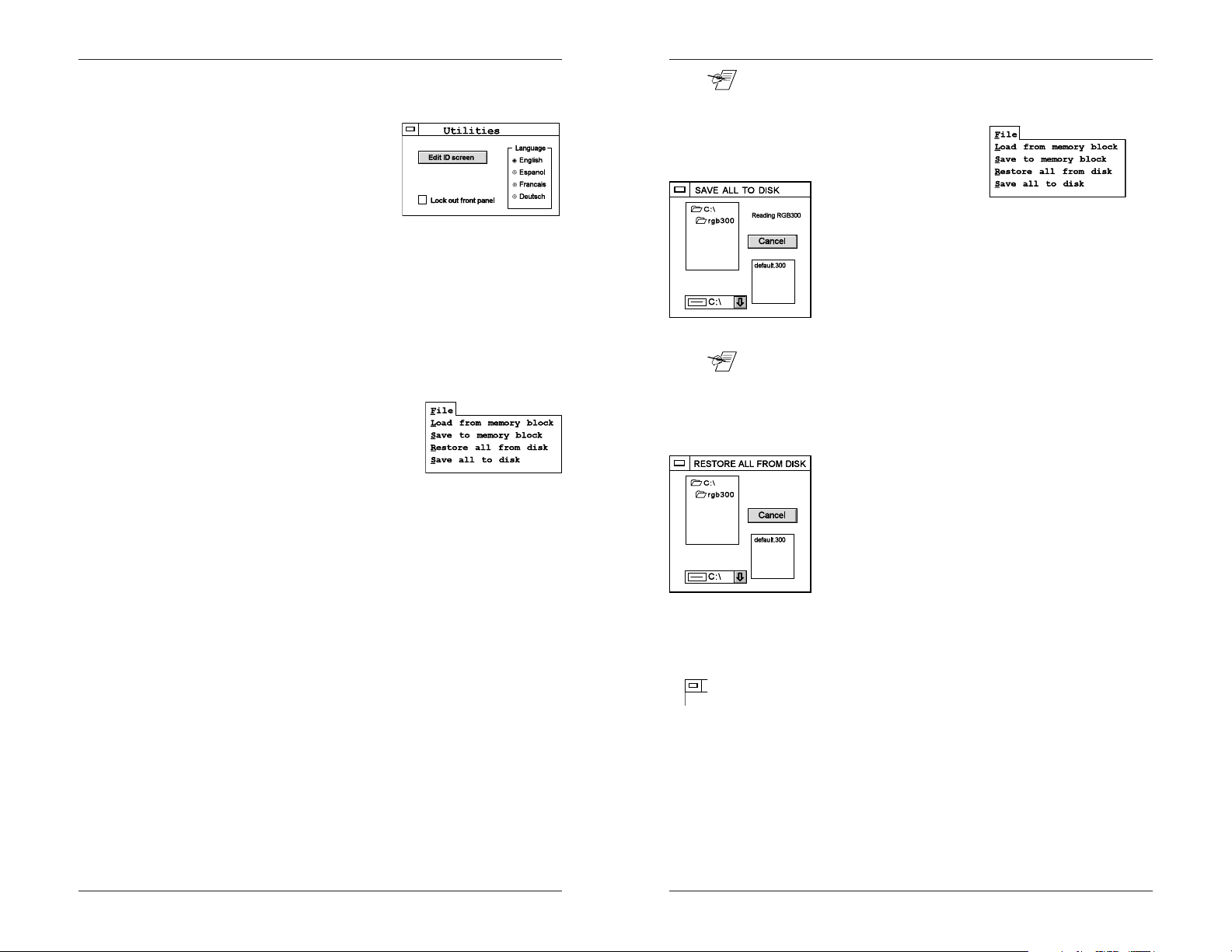
Using the Utility Menu
The utility menu is opened by clicking the Utilities item on the
menu bar. This screen allows the user to make the following
changes in the RGB 300.
· Click the circle next to the desired language to change the
language used by the menu.
· Click the box next to Lockout front panel to Lock or Unlock
the RGB 300 keyboard.
· Click on Edit ID Screen to display the current ID screen text.
"Edit ID screen" becomes "Save ID screen" and two text boxes
appear below it. Each box allows up
to 16 character spaces. The first box
is for the top line of the ID display and
the second box is for the bottom line.
New text can be entered in the two
boxes. Click on Save ID Screen to
store changes.
Using the File Menu
The File menu allows the user to load and save any presets
to/from the RGB 300 memory. It can also save and restore
the memory (all 25 blocks) to/from a disk file.
As described in Chapters two and three, the RGB 300 has 25
memory blocks, each of which can store a preset for a
specific scan rate. This includes the resolution, horizontal and
vertical frequencies, level, peaking, shift and sync settings. In
addition to the 25 blocks of memory presets, the RGB 300
software allows these blocks to be stored to a disk file. The
number of stored disk files is up to the user.
Extron has provided a file called "default.300" that is loaded
with the software. This file contains all the information
required to restore the RGB 300 to condition it was in when it
shipped.
____ Using the following features to save and restore scan rate
configurations to/from disk allows for a virtually unlimited
number of configurations to be saved, and loaded when
needed.
Save All Memory Blocks To Disk
This function allows the user to
save all the presets in the
RGB 300 memory blocks,
together with the ID screen. To use this function click
on the File menu then click on Save all to disk. A
dialog box will appear showing any files already saved
on the current drive. A different drive (floppy or hard
drive) may be selected for saving the memory blocks,
and a new filename may be entered. When the data is
loaded from the RGB 300, a Save button appears.
Click Save to write the file to disk.
____ When saving a set of memory blocks to a file, give the file a
name that fits the application. This will make it easier to identify
for future use. The software adds ".300" to the filename.
Restore All Memory Blocks From Disk
This function loads the RGB 300 with presets and ID
screen from a disk file, such as those saved using the
previous utility. This can be used to “clone” an
RGB 300. Click on the File item in the menu bar, and
then click on Restore all from disk. A dialog box will
appear showing any files that were previously saved.
Click on the desired filename, and then on Load. The
process takes about 30 seconds.
Note: The RGB 300 will not select a new scan format until it detects a
change in the input sync, or the unit is reset (powered off and
on).
Exit
The RGB 300 software uses standard Windows® operation.
To close a Window, double-click on dash in a box in the upper
left corner of that Window. To exit the Utilities Menu, or the
RGB 300 program, double-click on the close button.
Load from a memory block
To load a memory block, click on the File item on the menu
bar, and then click on Load from a memory block. A box will
appear showing the current preset memory blocks in the
RGB 300. Click on the desired memory block and then click
Ok.
5-3
Extron RGB 300 Universal Interface • User’s Manual Extron RGB 300 Universal Interface • User’s Manual
5-4
Page 20

____
Chapter 5 • Using RGB 300 Windows® SoftwareChapter 5 • Using RGB 300 Windows® Software
RGB 300 Digital Universal Interface
User's manual
5-5
Programmer's Guide
Communication Format
Command Structure
Host-Initiated Commands
RGB 300-Initiated Commands
Command Descriptions
A
Extron RGB 300 Universal Interface • User’s Manual Extron RGB 300 Universal Interface • User’s Manual
Page 21

Communication Format
This detailed programming guide is for the user who plans to
write his/her own software for controlling the RGB 300. It is
not related to do with the Windows software described in
Chapter 4. Knowledge of hexadecimal and binary numbers is
recommended when writing programs for the RGB 300.
Number conversion is discussed on A-5.
Communication Format
The information exchange between the RGB 300 and a Host
system (connected to the RS- 232 control port) is based on a
proprietary format and protocol. The information is byte
oriented. The numeric value of each byte determines how it is
interpreted, in one of three categories:
1. Communication control. 00 thru 1F hex (0 thru 31 decimal)
2. Command codes. 20 thru 7F hex (32 thru 127 decimal)
3. Specific data. 80 thru FF hex (127 thru 255 decimal)
Command Structure
Commands from the Host system are made up as follows:
1. Command Code, followed by:
2. Data (if any), followed by:
3. Checksum, followed by:
4. End of transmission mark
Command Codes (20 thru 7F hex)
The command code is one byte, having a value ranging from
20 to 7F hex. However, the command codes used by the
RGB 300 are:
30 thru 48 hex for Commands, and 70 thru 73 for Reports.
They are listed and described later.
Data Bytes (80 thru FF hex)
Data can follow the Command Code for three reasons:
1. If the Host is sending new settings to the RGB 300, data
bytes will contain that new information.
2. Data byte(s) may be needed to make the command more
specific. For example, to tell the RGB 300 to load a new
block number, a data byte is needed to specify the block
number.
3. When the RGB 300 responds to a request for information, it
returns the original command code, followed by data bytes.
____ A data byte always has bit 7 set. Bits 0 thru 6 may be binary
encoded, or they may represent numbers 00 thru 7F hex
(decimal 0 thru 127) In the examples that follow, the value 80
hex (or 128 decimal) is often added to the information. This
makes it a data byte.
Appendix A • Programmer's Guide Appendix A • Programmer's Guide
Checksum
The checksum is a two byte field (CKS1 & CKS2) built
according to the following procedure:
1. The binary sum (2-bytes) is calculated for all command code
and data bytes.
Example: A2B7 hex. is: 1010 0010 1011 0111 binary
2. The two most significant bits (15 & 14) are dropped. (lsb =
bit zero) Example: --10 0010 1011 0111 binary
3. The remaining 14 bits are split into two 7-bit fields
Example: --
4. Both 7-bit fields are padded with a “1” in the most significant
bit position, thus creating two “data type” bytes. Example:
110 0010 1 & 1011 0111 binary (C5 & B7 hex)
5. CKS1 is the most significant byte (C5), and is transmitted
first, followed by CKS2, the least significant byte (B7) of the
Checksum.
Alternate Checksum Calculation in Decimal
1. Add all transmitted bytes starting with the command code
and ending with the last data byte.
Example: 41, 655 decimal
2. If the sum is more than 16, 384 then subtract 16, 384 from it.
Example: 41, 655 - 16, 384 = 25, 271
2.a. Repeat this step until the sum is less than 16, 384.
Example: 25, 271 - 16, 384 = 8, 887
3. Divide the result from step 2 by 128
Example: 8, 887/128 = 69.429
4. Take the integer portion of the result (69) from step 3 and
add 128 Example: 69 + 128 = 197 decimal This is the first
checksum byte CKS1.
5. Take the integer portion of the result (69) from step 3 and
multiply by 128. Example: 69 x 128 = 8, 832
7. Take the result from step 5 (8, 832) and subtract it from the
result of step 2 (8, 887), and add 128 to the result.
Example: 8, 887 - 8, 832 = 55, + 128 = 183 decimal.
This becomes the second byte CKS2
End Of Transmission
This is always the single character EOT (04h).
Checksum
10 0010 1 & 011 0111 binary (45/37 hex)
A-1
Extron RGB 300 Universal Interface • User’s Manual Extron RGB 300 Universal Interface • User’s Manual
A-2
Page 22
Checksum
Disabling the Checksum feature
The Checksum feature can be disabled by using the following
procedure.
____ Although checking of the Checksum can be overridden, the
Checksum bytes must be there. Since they are not checked,
they can be 80h-FFh.
1. Remove power from the RGB 300 and disconnect any
cables.
Appendix A • Programmer's Guide Appendix A • Programmer's Guide
Host Initiated Communication (CMDn)
Commands originating with the Host, can either send
information to the RGB 300, or request information from the
RGB 300. After receiving a command, the RGB 300 executes
it and sends a Response back to the Host. The Response
format (below) repeats the command code, followed by an
error code and any data requested. The format of the
Response is similar to the that of the original Command, with
the added error code (ERC).
1. Command code CMD
2. Error code ERC
3. Data (if any)
4. Checksum CKS1+CKS2
5. End of transmission EOT
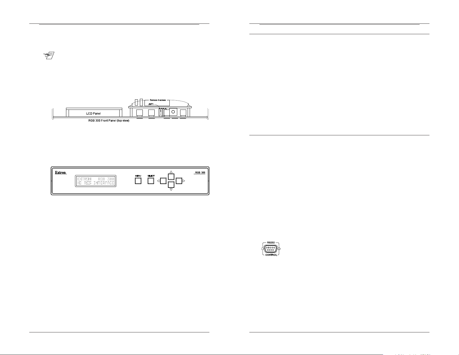
Communication Protocol
2. Turn the case up-side-down and remove the four screws
holding the case together.
3. Turn the case right-side-up and carefully remove the top half
of the case. This exposes the main board and the back of
the front panel (shown below).
4. Slide the Front Panel upward and out of the grooves in the
side of the case.
5. Locate the four (4) screws that hold the circuit board for the
panel buttons and remove them. (See picture above.)
6. Pull the circuit board away from the panel and remove
jumper JMP1. Do not remove JMP2.
7. Use the four screws to reattach the button circuit board to
the panel and insert the panel back into the grooves in the
side of the case.
8. Put the top cover on the case. Note that the cover can only
go on one way, because of the slots in the upper and lower
halves of the case.
9. Holding the case tightly together, turn it up-side-down and
assemble it with the four screws removed in step 2.
RGB 300 Initiated Communication (RPRTn)
Commands originating with the RGB 300 are called “reports”
If the RGB 300 detects certain changes in status, it reports
this to the Host system. For example: when the scan rate has
changed, the unit has been turned off-line; etc. These reports
follow the same general command format, except that no
response is expected from the Host.
Timing
When Commands are sent to the RGB 300, the Response will
always be delayed due to normal processing time. This delay
has two components:
1. Communications delay on the RS-232 bus.
2. RGB 300 processing time.
The total delay is typically less than 100 msec.
RS-232 Connector Pin-outs
RS-232 Connector Pins are as follows:
Pin 1 N/C (not connected)
Pin 2 TD Transmit Data (data out of the RGB 300)
Pin 3 RD Receive Data (data into the RGB 300)
Pin 4 N/C
Pin 5 Ground
Pin 6 N/C
Pin 7 Reserved
Pin 8 N/C
Pin 9 N/C
A-3
10. Put the RGB 300 back in working order by attaching
cables, power, etc.
Extron RGB 300 Universal Interface • User’s Manual Extron RGB 300 Universal Interface • User’s Manual
A-4
Page 23

Command List
Command List
Command Hex Page Description
CMD0 30 A-7 Report measured scan rate
CMD1 31 A-8 Report contents of ID screen
CMD2 32 A-9 Report RGB code (video detector)
CMD3 33 A-10 Report programmed sync code
CMD4 34 A-10 Report software version
CMD5 35 A-11 Report actual sync code
CMD6 36 A-11 Report video level
CMD7 37 A-12 Set video level
CMD8 38 A-12 Report horizontal shift
CMD9 39 A-13 Set horizontal shift
CMD103A A-13 Report vertical shift
CMD113B A-14 Set vertical shift
CMD123C A-14 Report peaking level
CMD133D A-14 Set peaking level
CMD143E A-15 Report menu language
CMD153F A-15 Set menu language
CMD1640 A-15 Report current block number
CMD1741 A-16 Select new block number
CMD1842 A-16 Report fade to black status
CMD1943 A-16 Set fade to black status
CMD2044 A-17 Report keyboard lock status
CMD2145 A-17 Set keyboard lock status
CMD2246 A-18 Program ID screen
CMD2347 A-19 Save current in memory block
CMD2448 A-19 Read name of memory block
Reports
RPRT070 A-20 Signal change
RPRT171 A-20 New block selected
RPRT272 A-20 Entered menu mode (local)
RPRT373 A-20 Exited menu mode (remote)
Communications Control
EOT 04 End of transmission
XON 11 Resume transmission
XOFF 13 Interrupt transmission
Appendix A • Programmer's Guide Appendix A • Programmer's Guide
Binary/hex/decimal Conversion Table
(auto-selected)
Bit #s in byte: 7 6 5 4 3 2 1 0
Decimal value = n/a 64 32 16 8 4 2 1
Dec. HexAdd the decimal values above for equivalents.
0 80/00h n/a 0 0 0 0 0 0 0
1 81/01h n/a 0 0 0 0 0 0 1
2 82/02h n/a 0 0 0 0 0 1 0
3 83/03h n/a 0 0 0 0 0 1 1
4 84/04h n/a 0 0 0 0 1 0 0
5 85/05h n/a 0 0 0 0 1 0 1
6 86/06h n/a 0 0 0 0 1 1 0
7 87/07h n/a 0 0 0 0 1 1 1
8 88/08h n/a 0 0 0 1 0 0 0
9 89/09h n/a 0 0 0 1 0 0 1
10 8A/0Ah n/a 0 0 0 1 0 1 0
11 8B/0Bh n/a 0 0 0 1 0 1 1
12 8C/0Ch n/a 0 0 0 1 1 0 0
13 8D/0Dh n/a 0 0 0 1 1 0 1
14 8E/0Eh n/a 0 0 0 1 1 1 0
15 8F/0Fh n/a 0 0 0 1 1 1 1
16 90/10h n/a 0 0 1 0 0 0 0
etc.
32 A0/20h n/a 0 1 0 0 0 0 0
etc.
64 C0/40h n/a 1 0 0 0 0 0 0
etc.
99 E3/63h n/a 1 1 0 0 0 1 1
100 E4/64h n/a 1 1 0 0 1 0 0
etc.
127 FF/7Fh n/a 1 1 1 1 1 1 1
Converting numbers
The table below shows how to convert data bytes from one
numbering system to another. One byte is 8 bits, or 2 hex
characters. In RGB 300 communications, all data bytes are
identified by having bit 7 = 1, therefore it is not included in the
following computations. The first hex value shows the number
as a data byte and the second is data value (example: 86/
06h).
A-5
Example: Bit #s in byte: 7 6 5 4 3 2 1 0
Dec. value = n/a 64 32 16 8 4 2 1
Ignore bit 7 and add the binary values for decimal equivalents.
Hex D3/53h = n/a 1 0 1 0 0 1 1
Decimal equivalent = 64 + 16 + 2 + 1 = 83d.
Extron RGB 300 Universal Interface • User’s Manual Extron RGB 300 Universal Interface • User’s Manual
A-6
Page 24

Using Commands - CMD0
Using Commands
The command descriptions that follow use hexadecimal and
binary numbering systems. The command breakdown is
explained on page A-1 and numbering conversion is
explained on A-5. If it is necessary to convert to decimal,
review to those sections.
CMD0 (30) - Report Scan Rate
The Host asks RGB 300 to report the current scan rate
frequencies. The RGB 300 responds with the frequencies
detected from the video input. Of the 12 data bytes, six are for
horizontal and six for vertical frequency. One data byte
represents one digit, or the decimal point.
Format:
CMD0, CKS1, CKS2, EOT
(30h), (80h), (B0h), (04h)
Response: CMD0, ERC, data1, data2, data3, data4, data5,
data6, data7, data8, data9, data10, data11, data12, CKS1,
CKS2, EOT
Where:
Horizontal Frequency, in kHz
data1 = ascii code for hundreds position, + 80h i.e., X00.00 kHz
data2 = ascii code for tens position, + 80h i.e., 0X0.00 kHz
data3 = ascii code for ones position, + 80h i.e., 00X.00 kHz
data4 = ascii code for a decimal point + 80h
data5 = ascii code for tenths position, +80h i.e., 000.X0 kHz
data6 = ascii code for hundredths position, + 80h i.e., 000.0X kHz
Vertical Frequency in Hz
data7 = ascii code for hundreds position, + 80h i.e., X00.00 Hz
data8 = ascii code for tens position, +80h i.e., 0X0.00 Hz
data9 = ascii code for ones position, + 80h i.e., 00X.00 Hz
data10 = ascii code for decimal point + 80h
data11 = ascii code for tenths position, + 80h i.e., 000.X0 Hz
data12 = ascii code for hundredths position, + 80h i.e., 000.0X Hz
Appendix A • Programmer's Guide Appendix A • Programmer's Guide
CMD1 (31) - Report Contents of ID Screen
The Host asks the RGB 300 to send the text that is
programmed to the ID screen. The RGB 300 responds with
the information shown in the LCD display. Bits 0-6 of each
data byte represents one alpha-numeric digit, and bit 7 is set.
Format:
CMD1, CKS1, CKS2, EOT
(31h), (80h), (B1h), (04h)
Response:
CMD1, ERC, data1, data2, ......, data32, CKS1, CKS2, EOT
Data bytes always have bit 7 = 1.
Where: data1 = ascii code of character 1 (on the first line of
display) + 80h
data2 = ascii code of character 2 + 80h
data3 = ascii code of character 3 + 80h
data4 = ascii code of character 4 + 80h
data5 = ascii code of character 5 + 80h
data6 = ascii code of character 6 + 80h
data7 = ascii code of character 7 + 80h
data8 = ascii code of character 8 + 80h
data9 = ascii code of character 9 + 80h
data10 = ascii code of character 10 + 80h
data11 = ascii code of character 11 + 80h
data12 = ascii code of character 12 + 80h
data13 = ascii code of character 13 + 80h
data14 = ascii code of character 14 + 80h
data15 = ascii code of character 15 + 80h
data16 = ascii code of character 16 + 80h
data17 = ascii code of character 1
(on the 2nd line of display) + 80h
data18 = ascii code of character 2 + 80h
data19 = ascii code of character 3 + 80h
data20 = ascii code of character 4 + 80h
data21 = ascii code of character 5 + 80h
data22 = ascii code of character 6 + 80h
data23 = ascii code of character 7 + 80h
data24 = ascii code of character 8 + 80h
data25 = ascii code of character 9 + 80h
data26 = ascii code of character 10 + 80h
data27 = ascii code of character 11 + 80h
data28 = ascii code of character 12 + 80h
data29 = ascii code of character 13 + 80h
data30 = ascii code of character 14 + 80h
data31 = ascii code of character 15 + 80h
data32 = ascii code of character 16 + 80h
Using Commands - CMD1
A-7
Extron RGB 300 Universal Interface • User’s Manual Extron RGB 300 Universal Interface • User’s Manual
A-8
Page 25

Using Commands - CMD2
Appendix A • Programmer's Guide Appendix A • Programmer's Guide
CMD2 (32) Report RGB Code (video input detector)
The Host asks the RGB 300 which video signals are detected
on the R, G, and B inputs. The RGB 300 sends one data byte,
with a bit assigned to each color.
Using Commands - CMD3,4
CMD3 (33) - Report Programmed Sync Code
The Host asks the RGB 300 to report which sync code has
been set. The RGB 300 responds with a data byte containing
sync information.
Format:
CMD2, CKS1, CKS2, EOT
(32h), (80h), (B2h), (04h)
Response:
CMD2, ERC, data1, CKS1, CKS2, EOT
Where:
data1 is bit encoded as follows:
If bit 0 = 0, Red is detected, if 1, Red is not detected.
If bit 1 = 0, Green is detected, if 1, it is not detected.
If bit 2 = 0 Blue is detected, if 1, it is not detected.
bits 3 - 6 = not defined (can be 0’s or 1’s).
bit 7 = 1
Bit #s in byte: 7 6 5 4 3 2 1 0
Hex 8xh = 1 n/a n/a n/a n/a B G R
If Red, Green and Blue are detected, data1 = 80d.
If bits 3-6 =0s, the result will give one of the following results:
80h = Red, Green, and Blue are all detected
81h = Green and Blue are detected
82h = Red and Blue are detected
83h = Blue is detected
84h = Red and Green are detected
85h = Green is detected
86h = Red is detected
87h = None is detected
Format:
CMD3, CKS1, CKS2, EOT
(33h), (80h), (B3h), (04h)
Response:
CMD3, ERC, data1, CKS1, CKS2
Where:
data1 is bit encoded as follows:
bit0 = if 0, serrations are removed; if 1, they are passed.
bit1 = if 0, sync is forced negative; if 1, polarity follows input.
bit2 = if 0, original sync is active; if 1, sync is processed.
bit3 = if 0, no sync is added to green; if 1, composite sync is
added to the green video channel.
bit4 = if 0, composite sync is output on the H/HV connector;
if 1, horizontal sync only appears at the H/HV connector.
bit5-6 = reserved (can be 1’s or 0’s)
bit 7 = 1 must be set.)
____ These are the programmed sync options and will be overridden
by the RGB 300’s termination detection circuit. This circuit can
change where the sync is sent, regardless of bits 3 and 4.
CMD4 (34) - Report Software Version
The Host asks the RGB 300 for the software version number.
The RGB 300 responds with the version encoded in a data
byte.
Format:
CMD4, CKS1, CKS2, EOT
(34h), (80h), (B4h), (04h)
A-9
Response:
CMD4, ERC, data1, CKS1, CKS2, EOT
Where:
data1 = software version times 10, + 128
Bit #s in byte: 7 6 5 4 3 2 1 0
Dec. value = 128 64 32 16 8 4 2 1
If data1 = 8Dh = 1 0 0 0 1 1 0 1
Decimal equivalent = 128 + 8 + 4 + 1 = 141d.
Extron RGB 300 Universal Interface • User’s Manual Extron RGB 300 Universal Interface • User’s Manual
A-10
Page 26

Using Commands - CMD5,6
To convert this use the where data1 = 141:
1. disregard bit 7 (or subtract 128 from data1). (141 - 128 =
13)
2. divide step 1 result by ten. (13/10 1.3, this is version)
Appendix A • Programmer's Guide Appendix A • Programmer's Guide
CMD7 (37) - Set Video Level
The Host tells the RGB 300 to set the video level. The
command includes two data bytes that provide this
information. The data bytes are codes the same as in CMD6.
Using Commands - CMD7,8
CMD5 (35) - Report Actual Sync Code
The Host asks the RGB 300 for the sync code being used.
(This is the programmed code modified by the sync autoselect circuit.) The RGB 300 sends a data byte containing the
sync code.
Format:
CMD5, CKS1, CKS2, EOT
(35h), (80h), (B5h), (04h)
Response:
CMD5, ERC, data1, CKS1, CKS2, EOT
Where:
data1 is encoded same as CMD3.
CMD6 (36) - Report Video Level
The Host asks the RGB 300 for the current video level. The
RGB 300 responds with two data bytes: one for the ± sign,
and the other is a number for the level.
Format:
CMD6, CKS1, CKS2, EOT
(36h), (80h), (B6h), (04h)
Response:
CMD6, ERC, data1, data2, CKS1, CKS2, EOT
Where:
data1= sign byte: 81h = level is positive; 82h = level is
negative.
data2 = the number for the level, + 80h
Note: If data2 is 80h, the level number is zero and the level adjustment is
in the middle of its range.
Example:
if Level = -67 then response will be:
CMD6, ERC, data1, data2, CKS1, CKS2, EOT
(36h), (80h), (82h), (C3h), (83h), (FBh), (04h)
Format:
CMD7, data1, data2, CKS1, CKS2, EOT
(37h), (xx), (xx), (xx), (xx), (04h)
Where:
data1 = sign byte, 81h sets a positive video level;
82h sets a negative level.
data2 = the number for the level, + 80h
Example:
To set the video level to +50d (see table on page A-5) then:
a. data1 = 81h (sign is positive)
b. data2 = B2h, or, (50 = 32+16+2 = 32h + 128)
c. send the following transmission:
CMD7, data1, data2, CKS1, CKS2, EOT
(37h), (81h), (B2h), (82h), (EAh), (04h)
Response:
CMD7, ERC, CKS1, CKS2, EOT
CMD8 (38) - Report Horizontal Shift
The Host asks the RGB 300 for the horizontal information.
The RGB 300 responds with three data bytes: one for
“enabled” status, one for polarity (±) and one for the numeric
value.
Format:
CMD8, CKS1, CKS2, EOT
(38h), (80h), (B8h), (04h)
Response:
CMD8, ERC, data1, data2, data3, CKS1, CKS2, EOT
Where:
data1 = enable byte, if 81h, shift is on, if 80h, shift is off.
data2 = sign byte: 81h = shift is positive; 82h = shift is
negative.
data3 = horizontal shift value, plus 80h
____ If data3 is 80h, the level number is zero and the horizontal shift
adjustment is in its center position.
Example: if Horz. Shift = +22 and On, then response will be:
CMD8, ERC, data1, data2, data3, CKS1, CKS2, EOT
(38h), (80h), (81h), (81h), (96h), (84h), (D0h), (04h)
A-11
Extron RGB 300 Universal Interface • User’s Manual Extron RGB 300 Universal Interface • User’s Manual
A-12
Page 27

Using Commands CMD9,10
CMD9 (39) - Set Horizontal Shift
The Host tells the RGB 300 to set the horizontal shift. This
command is like CMD8, but the data is going the other way.
The command includes three data bytes for the horizontal
shift information.
Appendix A • Programmer's Guide Appendix A • Programmer's Guide
CMD11 (3B) - Set Vertical Shift
The Host tells the RGB 300 to set the vertical shift
information. This is like CMD10, but the data is going the
other direction. The command includes three data bytes to
provide the vertical settings.
Using Commands - CMD11,12,13
Format:
CMD9, data1, data2, data3, CKS1, CKS2, EOT
(39h), (xx), (xx), (xx), (ck), (ck), (04h)
Where:
data1 = enable byte, 80h turns off shift, 81h turns on shift.
data2 = sign byte, 81h sets a positive horizontal shift;
data3 = shift number, + 80h
Example:
CMD9, data1, data2, data3, CKS1, CKS2, EOT
(39h), (81h), (81h), (A2h), (83h), (DDh), (04h)
To set the horizontal shift to +34 (34d = 32+2 =22h) then:
a. data2 = 81h (sign is positive)
b. data3 = 34 (22h) + bit7 = A2h
c. send the following transmission
Response:
CMD9, ERC, CKS1, CKS2, EOT
CMD10 (3A) - Report Vertical Shift
The Host asks the RGB 300 for the current vertical shift
information. The RGB 300 responds with three data bytes:
one for “enabled” status, one for polarity (±) and one for the
numeric value.
Format:
CMD10, CKS1, CKS2, EOT
(3Ah) , (80h), (B8h), (04h)
Response:
CMD10, ERC, data1, data2, data3, CKS1, CKS2, EOT
Where:
data1 = enable byte: 80h = shift is off; 81h = shift is on.
data2 = sign byte: 81h = shift is positive; 82h = shift is
negative.
data3 = vert. shift + 80h
82h sets a negative horizontal shift.
Format:
CMD11, data1, data2, data3, CKS1, CKS2, EOT
(3Bh), (xx), (xx), (xx), (xx), (xx), (04h)
Where:
data1 = enable byte: 80h = shift is off; 81h = shift is on.
data1 = sign byte ; 81h = positive shift; 82h = negative shift.
data2 = shift + 80h
Response:
CMD11, ERC, CKS1, CKS2, EOT
Example:
To set the vertical shift to +34 (34d = 32+2 =22h) then:
a. data2 = 81h (sign is positive)
b. data3 = 34 (22h) + bit7 = A2h
c. send the following transmission
CMD11, data1, data2, data3, CKS1, CKS2, EOT
(3Bh), (81h), (81h), (A2h), (83h), (DFh), (04h)
CMD12 (3C) - Report Peaking Level
The Hosts asks the RGB 300 for the current peaking level.
The RGB 300 responds with a data byte containing the
peaking level value.
Format:
CMD12, CKS1, CKS2, EOT
(3Ch) , (80h), (BCh), (04h)
Response:
CMD12, ERC, data1, CKS1, CKS2, EOT
Where:
data1 = peaking level (0-7) + bit7 = 80-87h
CMD13 (3D) - Set Peaking Level
The Host tells the RGB 300 to set the peaking level. This is
like CMD12, but the Host sends the peaking level value in a
data byte.
A-13
____ If data3 is 80h, the level number is zero and the vertical
adjustment is in its center position.
Example:
if Vert. Shift = +22 and On then response will be:
CMD10, ERC, data1, data2, data3, CKS1, CKS2, EOT
(3Ah), (80h), (81h), (81h), (96h), (84h), (D2h), (04h)
Extron RGB 300 Universal Interface • User’s Manual Extron RGB 300 Universal Interface • User’s Manual
Format:
CMD13, data1, CKS1, CKS2, EOT
(3Dh), (xx), (xx), (xx), (04h)
Where:
data1 = peaking level (0-7) + 80h
A-14
Page 28

Using Commands - CMD14,15,16
Response:
CMD13, ERC, CKS1, CKS2, EOT
CMD14 (3E) - Report Menu Language
The Host asks the RGB 300 which language is currently being
used to display the menus. The RGB 300 responds with one
data byte with the language mode encoded.
Format:
CMD14, CKS1, CKS2, EOT
(3Eh), (80h), (BEh), (04h)
Response:
CMD14, data1, CKS1, CKS2, EOT
Where:
data1 = 80h for English
81h for Spanish
82h for German
83h for French
Appendix A • Programmer's Guide Appendix A • Programmer's Guide
CMD17 (41) - Select New Block Number
The Host tells the RGB 300 to load a preset configuration
from a memory block number. The block contains settings for
a different video format. See table for pre-loaded memory
blocks on page 3-4.
Format:
CMD17, data1, CKS1, CKS2, EOT
(41h), (xx), (ck), (ck), (04h)
Where:
data1= block number to load + 80h
Response:
CMD17, ERC, CKS1, CKS2, EOT
Video Fade Mode
Through RS-232 programming, or through Windows®
software, the RGB 300 can make the picture fade to black, or
from black to picture.
Using Commands - CMD17,18,19
CMD15 (3F) - Set Menu Language
The host tells the RGB 300 change menu displays to a
different language. This command includes a data byte to tell
the RGB 300 which language mode to set.
Format:
CMD15, data1, CKS1, CKS2, EOT
(3Fh), (xx), (xx), (xx), (04h)
Where:
data1 = 80h to set to English
81h to set to Spanish
82h to set to German
83h to set to French
Response:
CMD15, ERC, CKS1, CKS2, EOT
CMD16 (40) - Report Current Block Number
The Host asks the RGB 300 which memory block number is
currently being used. The RGB 300 responds with a data byte
containing the memory block number.
Format:
CMD16, CKS1, CKS2, EOT
(40h), - (80h), (C0h), (04h)
Response:
CMD16, data1, CKS1, CKS2, EOT
Where:
data1 = current memory block number + 80h
A-15
Extron RGB 300 Universal Interface • User’s Manual Extron RGB 300 Universal Interface • User’s Manual
____ Because there is no front panel control for this function, the
user must take care not to leave the RGB 300 in the fade
mode. If the unit is disconnected from power and reset then the
fade will default to off.
CMD18 (42) - Report Fade to Black Status
The Host asks the RGB 300 if the video is in the "fade" mode.
The RGB 300 responds with a data byte telling if this is true or
false.
Format:
CMD18, CKS1, CKS2, EOT
(42h), - (80h), (C2h), (04h)
Response:
CMD18, data1, CKS1, CKS2, EOT
Where:
data1 = 80h if video is not in the fade-to-black mode.
81h if video is fade-to-black mode.
CMD19 (43) - Set the Video Fade Status
The Host tells the RGB 300 to fade the video in or out.
Format:
CMD19, data1, CKS1, CKS2, EOT
(43h), - (xx), - (xx), - (xx), (04h)
Where:
data1 = 80h to fade the video in
81h to fade video out (to black)
A-16
Page 29

Using Commands - CMD20,21
Response:
CMD19, ERC, CKS1, CKS2, EOT
CMD20 (44) - Report Keyboard Lock Status
The Host asks the RGB 300 if the keyboard is locked or
unlocked. The RGB 300 responds with a data byte containing
this information.
Format:
CMD20, CKS1, CKS2, EOT
(44h), (80h), (C4h), (04h)
Response:
CMD20, data1, CKS1, CKS2, EOT
Where:
data1 = 80h if keyboard is unlocked;
81h if keyboard is locked
CMD21 (45) - Set Keyboard Lock Status
The Host tells the RGB 300 to lock or unlock the keyboard.
The command includes a data byte to provide this
information.
Format:
CMD21, data1, CKS1, CKS2, EOT
(45h), - (xx), (cc), (cc), (04h)
Where:
data1= 80h to Unlock the keyboard;
81h to Lock the keyboard
Response:
CMD21, ERC, CKS1, CKS2, EOT
Appendix A • Programmer's Guide Appendix A • Programmer's Guide
CMD22 (46) - Program ID Screen
The Host tells the RGB 300 to change the contents of the ID
screen. The command includes 32 data bytes of ascii
information - 16 bytes for the first line and 16 for the second
line.
Note: Refer to an ASCII table for the necessary codes and set bit7 on.
Format:
CMD22, data1, data2, .- - - , data32, CKS1, CKS2, EOT
Where:
data1 = ascii code of character 1 (on 1st line of display) +
80h
data2 = ascii code of character 2 + 80h
data3 = ascii code of character 3 + 80h
data4 = ascii code of character 4 + 80h
data5 = ascii code of character 5 + 80h
data6 = ascii code of character 6 + 80h
data7 = ascii code of character 7 + 80h
data8 = ascii code of character 8 + 80h
data9 = ascii code of character 9 + 80h
data10 = ascii code of character 10 + 80h
data11 = ascii code of character 11 + 80h
data12 = ascii code of character 12 + 80h
data13 = ascii code of character 13 + 80h
data14 = ascii code of character 14 + 80h
data15 = ascii code of character 15 + 80h
data16 = ascii code of character 16 + 80h
data17 = ascii code of character 1 (2nd line of display) +
80h
data18 = ascii code of character 2 + 80h
data19 = ascii code of character 3 + 80h
data20 = ascii code of character 4 + 80h
data21 = ascii code of character 5 + 80h
data22 = ascii code of character 6 + 80h
data23 = ascii code of character 7 + 80h
data24 = ascii code of character 8 + 80h
data25 = ascii code of character 9 + 80h
data26 = ascii code of character 10 + 80h
data27 = ascii code of character 11 + 80h
data28 = ascii code of character 12 + 80h
data29 = ascii code of character 13 + 80h
data30 = ascii code of character 14 + 80h
data31 = ascii code of character 15 + 80h
data32 = ascii code of character 16 + 80h
Using Commands - CMD22
A-17
Response:
CMD22, ERC, CKS1, CKS2, EOT
Extron RGB 300 Universal Interface • User’s Manual Extron RGB 300 Universal Interface • User’s Manual
A-18
Page 30

Using Commands - CMD23,24
Appendix A • Programmer's Guide Appendix A • Programmer's Guide
CMD23 (47) - Save Current In Memory Block
The Host tells the RGB 300 to save the current settings in a
specific memory block, and give it a name. This command
includes seven data bytes to provide the memory block
number, and the ascii characters that make up the name.
Note: Refer to an ASCII table for the necessary codes and set bit7 on.
Format:
CMD23, data1, data2, data3, data4, data5, data6, data7,
CKS1, CKS2, EOT
(47h), - (xx), (xx), (xx), (xx), (xx), (xx), (xx), (xx), (xx), (04h)
Where:
data1 = block number to save in (1-25) + 80h
data2 = ascii code of first character of name + 80h
data3 = ascii code of second character of name + 80h
data4 = ascii code of third character of name + 80h
data5 = ascii code of forth character of name + 80h
data6 = ascii code of fifth character of name + 80h
data7 = ascii code of sixth character of name + 80h
Response:
CMD23, ERC, CKS1, CKS2, EOT
CMD24 (48) - Read Name Of Memory Block
The Host asks the RGB 300 send the name of a specific
memory block #xx. The RGB 300 responds with six data
bytes containing the ascii code for the characters that make
up the block name.
Using Commands - RPRT0,1,2,3
RPRT commands are generated when something changes in
the RGB 300. These status change commands are described
here.
RPRT0 (70) - Signal Change
The RGB 300 has detected a change in the incoming Sync
signals, causing it to automatically select a new memory
block. The report includes a data byte containing the number
of the new memory block.
Format:
RPRT0, data1, CKS1, CKS2, EOT
(70h), (xx), (xx), (xx), (04h)
Where:
data1 = the number of the selected memory block (1-25) +
80h
RPRT1 (71) - New Block Selected
The RGB 300 is informing the Host that the user has manually
selected a new memory block from the Front Panel. The
report includes a data byte containing the number of the new
memory block.
Format:
RPRT1, data1, CKS1, CKS2, EOT
(71h), (xx), (xx), (xx), (04h)
Where:
data1 = the number of the new memory block (1-25) + 80h
A-19
____ There are 25 memory blocks. The first 14 are loaded at the
factory with some popular video configurations. See list on
page 3-4.
Format:
CMD24, data1, CKS1, CKS2, EOT
(48h), - (xx), (xx), (xx), (04h)
Where:
data1 = number of the block from which to read name.
Response:
CMD24, data2, data3, data4, data5, data6, data7, CKS1,
CKS2, EOT
Where:
data2 = ascii code of first character + 80h
data3 = ascii code of second character + 80h
data4 = ascii code of third character + 80h
data5 = ascii code of forth character + 80h
data6 = ascii code of fifth character + 80h
data7 = ascii code of sixth character + 80h
Extron RGB 300 Universal Interface • User’s Manual Extron RGB 300 Universal Interface • User’s Manual
RPRT2 (72) - Entered Menu Mode (local)
The RGB 300 is informing Host that it has entered local menu
mode (someone is using the Front Panel) and no remote
commands can be honored until it returns to default mode.
Format:
RPRT2, CKS1, CKS2, EOT
(72h), (80h), (F2h), (04h)
RPRT3 (73) - Exited Menu Mode (remote mode)
The RGB 300 is informing Host it has exited menu mode and
is now ready to accept commands from the Host.
Format:
RPRT3, CKS1, CKS2, EOT
(73h), (80h), (F3h), (04h)
This concludes the programming information.
A-20
Page 31

____
Appendix A • Programmer's Guide
A-21
Extron RGB 300 Universal Interface • User’s Manual
 Loading...