

Page 1
POWER
Fiber Optic Test Set • Setup Guide
This guide provides instructions for an experienced
technician to begin using the Extron Fiber Optic Power
Meter (FPM 101) and Light Source (FLS 101).
The Extron Fiber Optic Test Set includes all the tools needed to measure optical
power and cable loss in multimode (MM) and singlemode (SM) fiber optic AV
equipment and fiber optic cabling. The light source includes both a multimode LED
output that operates at 850 nanometers (nm) and 1300 nm, and a singlemode laser
output that operates at 1310 nm and 1550 nm. The power meter is compatible
with both multimode and singlemode fiber and measures optical power in dBm or
microwatts (µW) and insertion loss in dB.
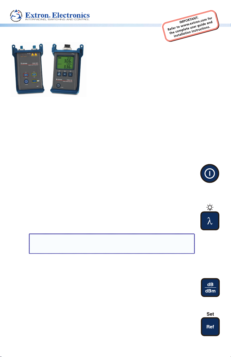
FPM 101 Function Buttons
Power
This button provides two functions:
z Press and hold to turn the power meter on. The meter turns off after five
minutes of inactivity.
z With the power meter on, press and hold to disable or enable the auto off
feature.
Wavelength/Backlight
This button provides two functions:
z Press and release to manually cycle through the calibrated wavelengths in the
following order:
850 nm > 1300 nm > 1310 nm > 1490 nm > 1550 nm > 850 nm ...
NOTE: When the power meter is receiving a wavelength ID indication
(WAVE ID) from the FLS 101 light source, it automatically switches to
the WAVE ID wavelength.
z With the power meter on, press and hold to toggle the backlight on or off.
dB/dBm/µW
This button provides two functions:
z Press and release to toggle display readings between insertion loss (dB) and
power (dBm).
z Press and hold to view power in microwatts (µW).
Ref/Set
This button provides two functions:
z Press and release to display the stored reference level for the currently
selected wavelength or the stored reference levels for multiple wavelengths.
z Press and hold until HELD SET is displayed to store the currently measured
level, or multiple levels, as the new reference.
µW
1
Page 2
FPM/FLS 101 • Quick Start Guide (Continued)
Single and Dual WAVE ID mode
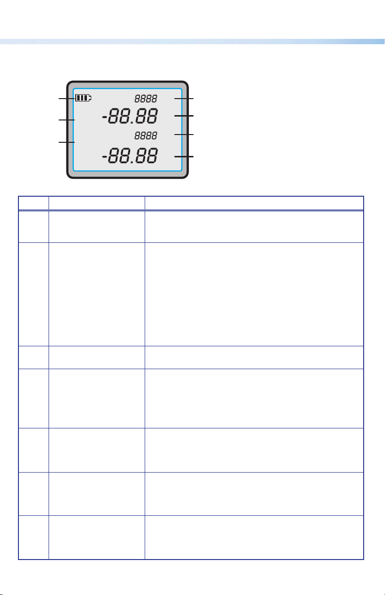
FPM 101 Display Readings
The following table lists the display readings for the FPM 101 power meter.
C
REF
D
WAVE ID
E
Item Field Description
Battery status indicator Displays approximate remaining battery life. When
a
REF indicator Press the REF button to toggle through stored reference
b
WAVE ID indicator Displayed when a wavelength has been identified using
c
Wavelength CW mode: Displays the currently enabled wavelength.
d
Power Displays measured power (dBm or µW), or insertion
e
Wavelength / Tone CW mode: Displays detected tone modulation frequency
f
Power
g
(Dual WAVE ID mode
only)
nm
µW
dB dBm
Hz
nm
µW
dB dBm
the indicator flashes, the batteries should be changed
immediately.
values. The reference values for the currently selected
wavelength (CW) or detected WAVE ID wavelengths will
be displayed briefly in the following order:
CW mode: The reference value will be displayed in field
Single WAVE ID mode: The reference value will be
displayed in field
Dual WAVE ID mode: The reference values will be
displayed in fields
the WAVE ID feature.
Single WAVE ID mode: Displays the detected WAVE ID
wavelength.
Dual WAVE ID mode: Displays the first detected WAVE ID
wavelength.
loss (dB) at the wavelength displayed in field
If power or loss is too high or too low for accurate
measurement, this field will display HI or LO.
in hertz (Hz).
Dual WAVE ID mode: Displays the second WAVE ID
wavelength.
Displays measured power (dBm or µW), or insertion
loss (dB) at the wavelength displayed in field
If power or loss is too high or too low for accurate
measurement, this field will display HI or LO.
F
G
H
I
e
.
e
and g.
d
f
.
e
.
.
2
Page 3
POWER
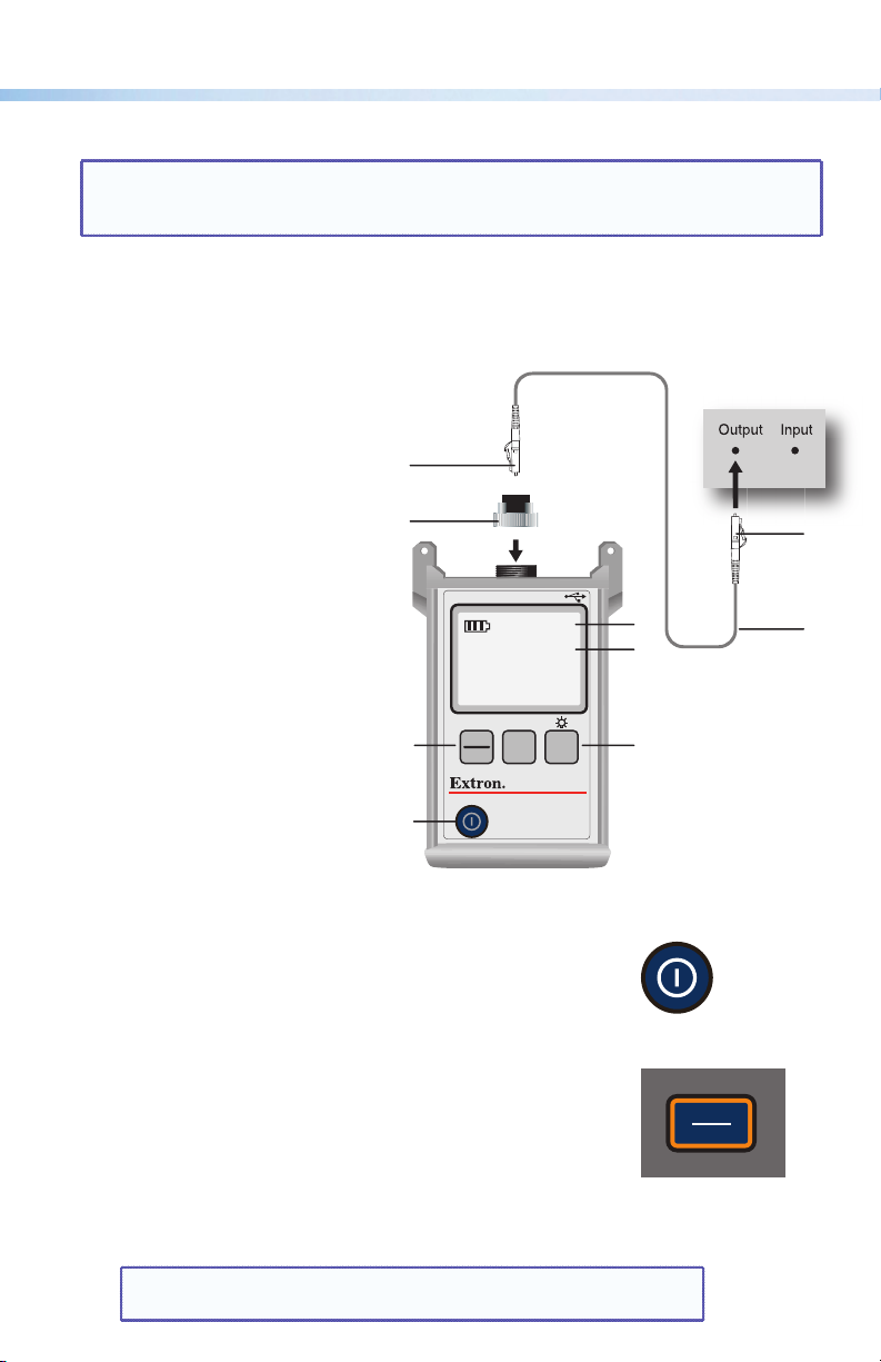
Measuring Optical Power
NOTE: It is important to keep all optical connections and surfaces clean to ensure
accurate measurements and operation. Always clean reference cables before
conducting tests.
1. Turn on the FPM 101.
2. Select the appropriate fiber optic reference cable. The reference cable fiber type
(SM or MM), must be the same as the type required by the output being measured.
3. Mount the appropriate adapter cap on the FPM 101 port.
4. Connect one end of the
reference cable to the adapter
cap and the other end to the
optical output to be measured.
5. Press the wavelength button
(see “Wavelength/Backlight”
on page 1) to select the
wavelength matching the
nominal wavelength of the
source being measured. The
selected wavelength is indicated
by
in the display.
e
6. Press the power selection
button (see “dB/dBm/µW” on
page 1) to display power in
dBm, or press and hold to display
power in µW. The power output
is indicated by
in the display.
f
d
c
f
a
WAVE ID
µW Set
dB
dBm
POWER
Adapter Cap
0000
0.00
0000
0.00
Ref
λ
FPM 101
FIBER POWER METER
Hz
nm
µW
dB
Hz
nm
µW
dB
e
f
e
Fiber Optic Equipment
d
Reference Cable
b
FLS 101 Function Buttons
Power Button
Press and hold to toggle the FLS 101 On or Off.
Multimode (MM) WAVE ID / CW Select
This button provides two functions:
z Press and release to cycle through output wavelengths in the
following order:
Dual 850/1300 nm > 850 nm > 1300 nm > dual 850/1300 nm > ...
z Press and hold to switch to CW mode at the current
wavelength, then press and hold the button again to select a
single wavelength in the following order:
850 nm > 1300 nm > 850 nm ...
NOTE: To switch back to WAVE ID mode, press and release the
button again.
CW
850nm
1300nm
MM
3
Page 4

FPM/FLS 101 • Quick Start Guide (Continued)
MM active output port indicators — Light to indicate the
wavelength of the MM output port.
z ON (continuous) — Single or dual WAVE ID mode
z ON (blinking) — CW mode
850nm
1300nm
Singlemode (SM) WAVE ID / CW Select
This button provides two functions:
z Press and release to cycle through output wavelengths in the
following order:
Dual 1310/1550 nm > 1310 nm > 1550 nm >
dual 1310/1550 nm > ...
z Press and hold to switch to CW mode at the current
wavelength, then press and hold the button again to select a
single wavelength in the following order:
1310 nm > 1550 nm > 1310 nm...
NOTE: To switch back to WAVE ID mode, press and release the
button again.
SM active output port indicators — Light to indicate the
wavelength of the SM output port.
z ON (continuous) — Single or dual WAVE ID mode
z ON (blinking) — CW or Tone (1550 nm only) mode
Tone (1550 nm, SM Only)
Press to toggle the 2 kHz tone on or off.
Tone indicator LED — Lights when the tone mode is active.
NOTE: When tone is active, the output is reduced by 3 dB.
External Power Indicator
Lights when the AC power adapter is connected and powered.
1310nm
1550nm
1310nm
CW
SM
1550nm
Low Battery Indicator
Lights to indicate low battery levels. Either change the batteries
or connect the AC power adapter to continue use.
4
Page 5

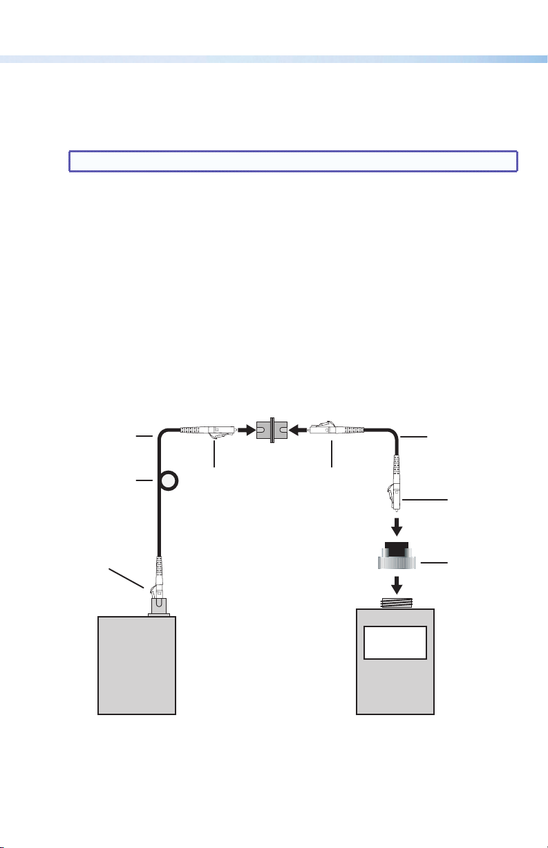
Testing Multimode or Singlemode Links
c
Verify the Transmit Reference Cable
1. Turn on the power meter and light source. Allow the light source to stabilize for a
minimum of two minutes prior to taking measurements.
2. Set the FLS 101 to the desired measurement wavelength.
a. Use WAVE ID to allow the FPM 101 to automatically read the wavelength.
b. If using CW, manually set the FPM 101 to the same wavelength.
3. Select and prepare the transmit reference cable. The fiber type, SM or MM, must match
the link to be tested.
a. MM: Wrap and secure the transmit reference cable five times around the included
mandrel.
b. SM (TIA testing only): Form and secure a 1.2 inch (30 mm) diameter loop in the
transmit reference cable.
NOTE: Clean both ends of the transmit reference cable before proceeding.
4. Connect the transmit reference cable to the FLS 101 output port (MM or SM).
5. Mount an adapter cap on the FPM 101. The adapter cap must match the free connector
on the transmit reference cable.
6. Connect the free end of the transmit reference cable to the power meter. If necessary
press the dB/dBm button to display optical power in dBm.
NOTE: The normal power range is -20 dBm for MM, 0 dBm for SM, (+/-1 dB).
Output power will be approximately 3 dB less if a 50 micrometer (µm)
mandrel-wrapped reference cable is used instead of a 62.5 µm or when the tone
feature is active.
7. If measured power is not within the acceptable range, or the display reads HI or LO,
clean all fiber connections and measure again. If cleaning fails, replace the transmit
reference cable and repeat steps 4 through 7.
8. To set the reference level for later use, press and hold the FPM 101 Ref/Set button until
HELD SET is displayed. The currently measured level is now the new reference level for
the active wavelength. Once the reference level is set, the FPM 101 switches to insertion
loss (dB) mode and the display reads 0 dB, ± 0.05 dB.
MM: Mandrel Wrap
(shown), or
SM: 1.2" (30 mm)
Dia Loop
Transmit Reference Cable
d
0 dB
FLS 101 FPM 101
f
e
5
Page 6
FPM/FLS 101 • Quick Start Guide (Continued)
Verify the Receive Reference Cable
9. Disconnect the transmit reference cable from the power meter.
10. Select and prepare the receive reference cable (fiber type, SM or MM, must match the
link to be tested).
NOTE: Clean both ends of the receive reference cable before proceeding.
11. Connect the receive reference cable to the FPM 101 using an appropriate adapter cap.
12. Connect the free ends of the transmit and receive reference cables together with a
coupler or at the bulkhead.
13. Verify the insertion loss (dB) of the transmit and receive reference cable pair is less than
0.75 dB, the maximum allowed by TIA standards (Extron recommends 0.4 to 0.5 dB).
If the insertion loss (dB) is not within these values:
z Disconnect the transmit and receive reference cables at the coupler (or bulkhead),
and clean the free ends of both reference cables and the coupler (or bulkhead).
Disconnect the receive reference cable from the power meter and clean it, then
repeat steps 11 through 13.
z If the value is still not acceptable, replace both reference cables and begin again
with step 1 on page 5.
Transmit Reference
Cable
MM: Mandrel Wrap or
SM: 1.2" (30 mm)
Dia Loop (Shown)
Do Not Remove
This Connection
FLS 101
N
Coupler
or
Bulkhead
Receive Reference
Cable
N
M
Adapter Cap
0.4 dB
FPM 101
6
Page 7

Insert the Link
14. Once the loss value is acceptable (< 0.75 dB) disconnect both the transmit and receive
reference cables from the coupler or bulkhead.
NOTE: Do not disturb either reference cable at their meter connections.
15. Insert the link to be tested by connecting it to the free ends of the transmit and receive
reference cables using appropriate couplings, or connect the reference cables to the
bulkhead connections of the link.
16. Observe the displayed value. The link cable insertion loss is displayed in dB. The two
examples below show a multimode and singlemode fiber link being measured using
dual WAVE ID.
The first example shows a multimode link. The 850 nm wavelength is reading a 3.65 dB
loss and the 1300 nm wavelength is reading a 4.07 dB loss.
The second example is a singlemode fiber. The 1310 nm wavelength is reading a 1.45 dB
loss and the 1550 nm wavelength is reading a 1.49 dB loss.
Transmit Reference
Cable
9V
850nm 1300nm 1310nm1550nm
Extron
FLS 101
FIBER LIGHT SOURCE
FIBER OPTIC LIGHT SOURCE
CWCW
1310nm
850nm
1550nm
1300nm
MM SM
Tone
POWER
Transmit Reference
Cable
9V
850nm 1300nm 1310nm1550nm
Extron
FLS 101
FIBER LIGHT SOURCE
FIBER OPTIC LIGHT SOURCE
CWCW
1310nm
850nm
1550nm
1300nm
MM SM
Tone
POWER
Mandrel
FLS 101
Fiber Optic
Light Source
Loop
FLS 101
Fiber Optic
Light Source
Coupler
or
Bulkhead
Coupler
or
Bulkhead
Multimode Fiber
Under Test
Singlemode Fiber
Under Test
Coupler
or
Bulkhead
FPM 101
Fiber Optic
Power Meter
Coupler
or
Bulkhead
FPM 101
Fiber Optic
Power Meter
Receive
Reference Cable
Optical Power Meter
850
3.65
WAVE ID
WAVE ID
1300
4.07
Set
dB
Ref
dBm
FPM 101
Extron
FIBER POWER METER
POWER
Receive
Reference Cable
Optical Power Meter
1310
1.45
WAVE ID
WAVE ID
1550
1.49
Set
dB
Ref
dBm
FPM 101
Extron
FIBER POWER METER
POWER
nm
nm
dB
dB
nm
nm
dB
dB
nm
nm
dB
dB
nm
nm
dB
dB
7
Page 8

FPM/FLS 101 • Quick Start Guide (Continued)
Included Accessories
z LC adapter cap for FPM 101
z LC output port adapter for FLS 101 (x2)
z LC reference cable, singlemode (x2)
z LC reference cable, multimode (x2)
z LC to LC coupler (x2)
z USB power cable
z Multimode cable mandrel, 62.5 µm
z Multimode cable mandrel, 50.0 µm
z FPM/FLS 101 Quick Start Guide
Extron USA - West
Headquarters
+800.633.9876
Inside USA and
Canada Only
+1.714.491.1500
+1.714.491.1517 FAX
Extron USA - East
+800.633.9876
Inside USA and
Canada Only
+1.919.863.1794
+1.919.863.1797 FAX
Extron Europe
+800.3987.6673
Inside Europe Only
+31.33.453.4040
+31.33.453.4050 FAX
Extron Asia
+800.7339.8766
Inside Asia Only
+65.6383.4400
+65.6383.4664 FAX
Extron Japan
+81.3.3511.7655
+81.3.3511.7656 FAX
Extron China
+400.883.1568
Inside China Only
+86.21.3760.1568
+86.21.3760.1566 FAX
© 2011 Extron Electronics All rights reserved. www.extron.com
Extron Middle East
+971.4.2991800
+971.4.2991880 FAX
68-2047-50
Rev. A 06 11
 Loading...