

Extron electronics Extender AAP, Extender Series, Extender WM, Extender D, Extender WM AAP User Manual
...Page 1

Extender Series
VGA-UXGA Line Drivers with Audio
User Guide
Distribution Amplifiers
68-552-01 Rev. M
01 19
Page 2

Safety Instructions
Safety Instructions • English
WARNING: This symbol, ,when used on the product, is
intended to alert the user of the presence of uninsulated dangerous
voltage within the product’s enclosure that may present a risk of electric
shock.
ATTENTION: This symbol, , when used on the product, is intended
to alert the user of important operating and maintenance (servicing)
instructions in the literature provided with the equipment.
For information on safety guidelines, regulatory compliances, EMI/EMF
compatibility, accessibility, and related topics, see the Extron Safety and
Regulatory Compliance Guide, part number 68-290-01, on the Extron
website, www.extron.com.
Sicherheitsanweisungen • Deutsch
WARNUNG: Dieses Symbol auf dem Produkt soll den Benutzer
darauf aufmerksam machen, dass im Inneren des Gehäuses dieses
Produktes gefährliche Spannungen herrschen, die nicht isoliert sind und
die einen elektrischen Schlag verursachen können.
VORSICHT: Dieses Symbol auf dem Produkt soll dem Benutzer in
der im Lieferumfang enthaltenen Dokumentation besonders wichtige
Hinweise zur Bedienung und Wartung (Instandhaltung) geben.
Weitere Informationen über die Sicherheitsrichtlinien, Produkthandhabung,
EMI/EMF-Kompatibilität, Zugänglichkeit und verwandte Themen finden Sie in
den Extron-Richtlinien für Sicherheit und Handhabung (Artikelnummer
68-290-01) auf der Extron-Website, www.extron.com.
Instrucciones de seguridad • Español
ADVERTENCIA: Este símbolo, , cuando se utiliza en el producto,
avisa al usuario de la presencia de voltaje peligroso sin aislar dentro del
producto, lo que puede representar un riesgo de descarga eléctrica.
ATENCIÓN: Este símbolo, , cuando se utiliza en el producto, avisa
al usuario de la presencia de importantes instrucciones de uso y
mantenimiento recogidas en la documentación proporcionada con el
equipo.
Para obtener información sobre directrices de seguridad, cumplimiento
de normativas, compatibilidad electromagnética, accesibilidad y temas
relacionados, consulte la Guía de cumplimiento de normativas y seguridad
de Extron, referencia 68-290-01, en el sitio Web de Extron, www.extron.com.
Instructions de sécurité • Français
AVERTISSEMENT : Ce pictogramme, , lorsqu’il est utilisé sur le
produit, signale à l’utilisateur la présence à l’intérieur du boîtier du
produit d’une tension électrique dangereuse susceptible de provoquer
un choc électrique.
Istruzioni di sicurezza • Italiano
AVVERTENZA: Il simbolo, , se usato sul prodotto, serve ad
avvertire l’utente della presenza di tensione non isolata pericolosa
all’interno del contenitore del prodotto che può costituire un rischio di
scosse elettriche.
ATTENTZIONE: Il simbolo, , se usato sul prodotto, serve ad
avvertire l’utente della presenza di importanti istruzioni di funzionamento
e manutenzione nella documentazione fornita con l’apparecchio.
Per informazioni su parametri di sicurezza, conformità alle normative,
compatibilità EMI/EMF, accessibilità e argomenti simili, fare riferimento
alla Guida alla conformità normativa e di sicurezza di Extron, cod. articolo
68-290-01, sul sito web di Extron, www.extron.com.
Instrukcje bezpieczeństwa • Polska
OSTRZEŻENIE: Ten symbol, , gdy używany na produkt, ma na celu
poinformować użytkownika o obecności izolowanego i niebezpiecznego
napięcia wewnątrz obudowy produktu, który może stanowić zagrożenie
porażenia prądem elektrycznym.
UWAGI: Ten symbol, , gdy używany na produkt, jest przeznaczony do
ostrzegania użytkownika ważne operacyjne oraz instrukcje konserwacji
(obsługi) w literaturze, wyposażone w sprzęt.
Informacji na temat wytycznych w sprawie bezpieczeństwa, regulacji
wzajemnej zgodności, zgodność EMI/EMF, dostępności i Tematy pokrewne,
zobacz Extron bezpieczeństwa i regulacyjnego zgodności przewodnik, część
numer 68-290-01, na stronie internetowej Extron, www.extron.com.
Инструкция по технике безопасности • Русский
ПРЕДУПРЕЖДЕНИЕ: Данный символ, , если указан
на продукте, предупреждает пользователя о наличии
неизолированного опасного напряжения внутри корпуса
продукта, которое может привести к поражению электрическим
током.
ВНИМАНИЕ: Данный символ, , если указан на продукте,
предупреждает пользователя о наличии важных инструкций
по эксплуатации и обслуживанию в руководстве,
прилагаемом к данному оборудованию.
Для получения информации о правилах техники безопасности,
соблюдении нормативных требований, электромагнитной
совместимости (ЭМП/ЭДС), возможности доступа и других
вопросах см. руководство по безопасности и соблюдению
нормативных требований Extron на сайте Extron: ,
www.extron.com, номер по каталогу - 68-290-01.
安全说明 • 简体中文
警告: 产品上的这个标志意在警告用户该产品机壳内有暴露的危险 电压,
有触电危险。
ATTENTION : Ce pictogramme, , lorsqu’il est utilisé sur le produit,
signale à l’utilisateur des instructions d’utilisation ou de maintenance
importantes qui se trouvent dans la documentation fournie avec le
matériel.
Pour en savoir plus sur les règles de sécurité, la conformité à la
réglementation, la compatibilité EMI/EMF, l’accessibilité, et autres sujets
connexes, lisez les informations de sécurité et de conformité Extron, réf.
68-290-01, sur le site Extron, www.extron.com.
注意: 产品上的这个标志意在提示用户设备随附的用户手册中有
重要的操作和维护(维修)说明。
关于我们产品的安全指南、遵循的规范、EMI/EMF 的兼容性、无障碍
使用的特性等相关内容,敬请访问 Extron 网站 , www.extron.com,参见
Extron 安全规范指南,产品编号 68-290-01。
Page 3

安全記事 • 繁體中文
警告: 若產品上使用此符號,是為了提醒 使用者,產品機殼內存在著
可能會導致觸電之風險的未絕緣危險電壓。
注意 若產品上使用此符號,是為了提醒使用者,設備隨附的用戶手冊中有
重 要 的 操 作 和 維 護( 維 修 )説 明 。
有關安全性指導方針、法規遵守、EMI/EMF 相容性、存取範圍和相關主題的詳細資
訊,請瀏覽 Extron 網站:www.extron.com,然後參閱《Extron 安全性與法規
遵守手冊》,準則編號 68-290-01。
安全上のご注意 • 日本語
警告: この記 号 が製品上に表示されている場合は、筐体内に絶縁されて
いない高電圧が流れ、感電の危険があることを示しています。
注意:この記号 が製品上に表示されている場合は、本機の取扱説明書に
記載されている重要な操作と保守( 整備)の 指示についてユーザーの注 意
を喚起するものです。
安全上のご注意、法規厳守、EMI/EMF適合性、その他の関連項目に
つ い て は 、エ クスト ロ ン の ウェ ブ サ イト www.extron.com よ り 『 Extron Safety
and Regulatory Compliance Guide』 ( P/N 68-290-01) をご覧ください。
안전 지침 • 한국어
경고: 이 기호 가 제품에 사용될 경우, 제품의 인클로저 내에 있는
접지되지 않은 위험한 전류로 인해 사용자가 감전될 위험이 있음을
경고합니다.
주의: 이 기호 가 제품에 사용될 경우, 장비와 함께 제공된 책자에 나와
있는 주요 운영 및 유지보수(정비) 지침을 경고합니다.
안전 가이드라인, 규제 준수, EMI/EMF 호환성, 접근성, 그리고 관련 항목에
대한 자세한 내용은 Extron 웹 사이트(www.extron.com)의 Extron 안전 및
규제 준수 안내서, 68-290-01 조항을 참조하십시오.
Copyright
© 2001-2019 Extron Electronics. All rights reserved. www.extron.com
Trademarks
All trademarks mentioned in this guide are the properties of their respective owners.
The following registered trademarks
(®)
, registered service marks
Extron Electronics (see the current list of trademarks on the Terms of Use page at www.extron.com):
Extron, Cable Cubby, ControlScript, CrossPoint, DTP, eBUS, EDID Manager, EDID Minder, Flat Field, FlexOS, Glitch Free, GlobalConfigurator,
GlobalScripter, GlobalViewer, Hideaway, HyperLane, IPIntercom, IPLink, KeyMinder, LinkLicense, LockIt, MediaLink, MediaPort,
NetPA, PlenumVault, PoleVault, PowerCage, PURE3, Quantum, Show Me, SoundField, SpeedMount, SpeedSwitch, StudioStation,
SystemINTEGRATOR, TeamWork, TouchLink, V-Lock, VideoLounge, VN-Matrix, VoiceLift, WallVault, WindoWall, XTP, XTPSystems, and ZipClip
Registered Service Mark
(SM)
: S3 Service Support Solutions
AAP, AFL (Accu-Rate Frame Lock), ADSP (Advanced Digital Sync Processing), Auto-Image, AVEdge, CableCover, CDRS (ClassD
Ripple Suppression), Codec Connect, DDSP (Digital Display Sync Processing), DMI (Dynamic Motion Interpolation), DriverConfigurator,
DSPConfigurator, DSVP (Digital Sync Validation Processing), eLink, EQIP, Everlast, FastBite, FOX, FOXBOX, IPIntercom HelpDesk, MAAP,
MicroDigital, Opti-Torque, PendantConnect, ProDSP, QS-FPC (QuickSwitch Front Panel Controller), Room Agent, Scope-Trigger, ShareLink,
SIS, SimpleInstructionSet, Skew-Free, SpeedNav, Triple-Action Switching, True4K, Vector™ 4K, WebShare, XTRA, and ZipCaddy
(SM)
, and trademarks
Registered Trademarks
Trademarks
(™)
(™)
are the property of RGB Systems, Inc. or
(®)
Page 4

FCC Class A Notice
This equipment has been tested and found to comply with the limits for a Class A digital
device, pursuant to part15 of the FCC rules. The ClassA limits provide reasonable
protection against harmful interference when the equipment is operated in a commercial
environment. This equipment generates, uses, and can radiate radio frequency energy and,
if not installed and used in accordance with the instruction manual, may cause harmful
interference to radio communications. Operation of this equipment in a residential area is
likely to cause interference. This interference must be corrected at the expense of the user.
NOTE: For more information on safety guidelines, regulatory compliances,
EMI/EMF compatibility, accessibility, and related topics, see the “Extron Safety and
Regulatory Compliance Guide” on the Extron website.
Battery Notice
This product contains a battery. Do not open the unit to replace the battery. If the battery
needs replacing, return the entire unit to Extron (for the correct address, see the Extron
Warranty section on the last page of this guide).
CAUTION: Risk of explosion. Do not replace the battery with an incorrect type. Dispose
of used batteries according to the instructions.
ATTENTION : Risque d’explosion. Ne pas remplacer la pile par le mauvais type de pile.
Débarrassez-vous des piles usagées selon le mode d’emploi.
Page 5

Conventions Used in this Guide
Notifications
The following notifications are used in this guide:
CAUTION: Risk of minor personal injury.
ATTENTION : Risque de blessure mineure.
ATTENTION:
• Risk of property damage.
• Risque de dommages matériels.
NOTE: A note draws attention to important information.
TIP: A tip provides a suggestion to make working with the application easier.
Software Commands
Commands are written in the fonts shown here:
^AR Merge Scene,,Op1 scene 1,1 ^B 51 ^W^C
[01] R 0004 00300 00400 00800 00600 [02] 35 [17] [03]
NOTE: For commands and examples of computer or device responses mentioned
in this guide, the character “0” is used for the number zero and “O” is the capital
letter “o.”
Computer responses and directory paths that do not have variables are written in the font
shown here:
Reply from 208.132.180.48: bytes=32 times=2ms TTL=32
C:\Program Files\Extron
Variables are written in slanted form as shown here:
ping xxx.xxx.xxx.xxx —t
SOH R Data STX Command ETB ETX
Selectable items, such as menu names, menu options, buttons, tabs, and field names are
written in the font shown here:
From the File menu, select New.
Click the OK button.
Specifications Availability
Product specifications are available on the Extron website, www.extron.com.
Extron Glossary of Terms
A glossary of terms is available at http://www.extron.com/technology/glossary.aspx.
Page 6

Page 7

Contents Contents
Introduction ...................................................1
About this Guide ................................................. 1
About the Extender Series VGA Line Drivers ....... 1
Differences Between the Models ..................... 1
Features ......................................................... 2
Installation ..................................................... 3
UL Guidelines ..................................................... 3
Installation Instructions ....................................... 3
Preparing the Site and Installing the Wall Box ..... 4
Considerations ............................................... 4
Procedure ....................................................... 4
Front Panel Features
and Cabling ....................................................... 7
Top, Rear, Bottom Panel Features and Cabling . 10
Mounting .......................................................... 13
Mounting the Extender AAP or
Extender AAP EX into an AAP Wallplate or
Device Faceplate ......................................... 13
Pre-installation Testing and Troubleshooting .. 14
Mounting the Extender WM or
Extender WM AAP to the Wall Box .............. 15
Mounting the Extender D .............................. 15
Mounting the Extender MK to the
Knockout Box.............................................. 16
Application Diagrams ........................................ 16
Reference Information ...............................18
Dimensions....................................................... 18
Extender AAP and Extender AAP EX
Dimensions .................................................. 18
Extender WM Dimensions ............................. 19
Extender WM AAP Dimensions ..................... 20
Extender WM AUS Dimensions ..................... 20
Extender MK Dimensions.............................. 21
Extender AKM UK Dimensions ..................... 21
Extender AKM MAAP Dimensions ................ 22
Extender D Dimensions ................................ 23
Cut-out Templates ............................................ 24
Extender WM Template ................................. 24
Extender WM AAP Template ......................... 25
Extender MK Template.................................. 26
Extender WM AUS Template ......................... 27
IPCP Pro Series • Contents vii
Page 8

IPCP Pro Series • Contents viii
Page 9

Introduction
This chapter covers the following topics:
• About this Guide — covers the scope of this guide and the terminology used in it
• About the Extender Series VGA Line Drivers— a description of the products, what
they do and how they differ
About this Guide
This guide contains information about the Extron Extender Series line drivers and on how
to operate and configure them. “Extender” and “line driver” are used to refer to all models
interchangeably when instructions apply to more than one model.
About the Extender Series VGA Line Drivers
The Extron Extender Series are one-input VGA-UXGA line drivers with audio. There are
seven models in the series:
• Extender AAP
• Extender AAP EX
• Extender WM
• Extender D
• Extender WM AAP
• Extender MK
• Extender AKM MAAP.
They boost the video signal between a laptop or desktop computer and a monitor or
projector. Each has a 300 MHz (-3 dB) video bandwidth.
Each line driver accepts one computer-video input and one stereo audio input. Each
Extender also features one buffered VGA-type RGB output and one stereo audio output.
With an optional Mac/VGA adapter, the Extender can also buffer signals from a Macintosh
computer.
Differences Between the Models
All Extender models are functionally identical but they have different mounting options.
For details about mounting the Extender AAP, Extender WM, Extender D,
Extender WM AAP, and the Extender MK, see Preparing the Site and Installing the Wall
Box starting on page4 in the installation section.
For Extender AAP EX mounting instructions, see the user guide or installation guide for the
appropriate model of Extron HSA Hideaway Surface Access enclosure.
For Extender AKM MAAP mounting instructions, see the Extender AKM MAAP Installation
Guide, available at http://www.extron.com.
Extender Series • Introduction 1
Page 10

Features
Video signal boosting — The selectable gain and peaking settings boost video signals to
compensate for signal degradation caused by long cables. The Extender can send a high
resolution signal up to 250 feet (75 m) through Extron M59 Series mini high resolution cable.
Sync restoration — Each Extender restores low level sync voltages found on many laptop
PCs (as low as two volts) to normal TTL levels.
Audio buffering — Unbalanced stereo audio inputs can be output as balanced audio for
long cable runs.
Extender Series • Introduction 2
Page 11

Installation
The following topics are covered in this chapter:
• UL Guidelines
• Installation Instructions
• Preparing the Site and Installing the Wall Box
• Front Panel Features and Cabling
• Top, Rear, Bottom Panel Features
• Mounting
• Application Diagrams
ATTENTION: Installation and service must be performed by authorized personnelonly.
This product should be used with a UL listed electrical box (see “UL Guidelines,”
below).
UL Guidelines
1. The Extender must be installed in an Underwriters Laboratories (UL) Listed junction
box. The UL approved electrical wall box (junction box) is not included with the unit; the
installer is responsible for obtaining and installing the box.
2. The unit must be installed with accordance with the National Electrical Code and with
local electrical codes.
Installation Instructions
Depending on the model, the Extenders can be mounted into furniture, a wall, an
Ackermann floorbox (see ackermann.co.uk), or an Extron HSA 400 Series or HSA 800
Series enclosure. Installation involves the following main steps:
1. Prepare the site, run cables, and install a wall box or floor box.
2. Cable rear panel connectors and set the gain switch.
3. Test the Extender.
4. Mount the Extender.
5. Attach input cables to the front panel.
For Extender AKM MAAP mounting instructions, see the AKM MAAP Installation Guide.
ATTENTION: The Extender must be installed in a UL listed wall box, which the installer
is responsible for obtaining.
For Extender AAP EX mounting instructions, see the user guide or installation guide for the
appropriate model of HSA Hideaway Surface Access enclosure.
NOTE: The Extender AAP EX does not require a wall box if it will be installed into an
Extron HSA 400 Series or HSA 800 Series surface access product. If you install an
ExtenderAAPEX without an HSA, you must use a wall box.
Extender Series • Installation 3
Page 12

Preparing the Site and Installing the Wall Box
Considerations
Choose a location that allows cable runs without interference. Allow enough depth for both
the wall box and the cables. You may need to install the cables into the wall, furniture, or
conduits before installing the line driver.
• The Extender AAP or Extender AAP EX can be installed in an Extron two-gang, four-
gang, or half rack width AAP Architectural Adapter Plate or in the faceplate of another
Extron device that accepts AAP plates, such as an interface or distribution amplifier.
See the mounting instructions for the adapter plate or device.
• The Extender AAP EX is usually installed into an Extron HSA 400 Series or
HSA 800 Series surface access enclosure.
• The Extender WM can be installed in a standard or compact one-gang electrical wall
box. This is also true for the Extender D, though it requires a standard decorator-style
wallplate.
• The Extender WM AAP can be installed in a three-gang wall box, and its faceplate
accepts up to four single height Extron Architectural Adapter Plates (AAPs).
• The Extender MK can be mounted into a standard, shallow knockout switch box (also
known as a KO box or MK box) that is used in Singapore, the United Kingdom, and
Australia.
The installation must conform to national and local electrical codes and to the Extender’s
size requirements. Dimensional drawings and templates are provided in Dimensions
starting on page18.
Procedure
1. See the template that corresponds to the Extender model and wall box being used.
NOTE: The templates are not shown at full size. Pay attention to the
2. Mark the guidelines for the opening on the wall or furniture.
3. Cut out the material from the marked area.
4. Check the opening size by inserting the wall box or the Extender (if no box is used)
5. Feed cables through the wall box punch-out holes and secure them with cable clamps
measurements shown on the templates.
• If the Extender will be installed in a wall box, place the box against the
installation surface and draw a line on it around the outside of the box.
• If the Extender will be installed without a wall box (using mud rings or
fastening it directly to the wall or furniture), measure and mark the surface for the
cutout area indicated in the template.
into the opening. The box and line driver should fit easily into the opening. Adjust the
opening as needed.
to provide strain relief.
Extender Series • Installation 4
Page 13

6. Exposed cable shields (braids or foil) are potential sources of short circuits. Trim back
x
Foil Shield
Cab
1-gang wall box.eps
Installation Cab
and insulate shields with heat shrink.
CAUTION: To prevent short circuits, the outer foil shield can be cut back to the
point where the cable exits the cable clamp. Both braided and foil shields should
be connected to an equipment ground at the other end of the cable.
Metal
Wall Bo
le Clamp
Install Cable
Screw
Braided
Shield
Figure 1. Grounding Outer Braided and Foil Shields
7. Insert the wall box into the opening, and attach it to the wall, stud, or furniture.
• For the Extender WM, Extender WM AAP, Extender D, and the Extender AAP or
Extender AAP EX (if installed in a two- or four-gang AAP plate), attach the wall box
to the wall stud or furniture with nails or screws, leaving the front edge flush with the
outer wall or furniture surface. See the following illustration, which applies to one-,
two-, three-, and four-gang wall boxes.
Wall Stud
le
Cable Clamp
Installation Cable
Wall Stud
Cable Clamp
Figure 2. Attaching a Wall Box to a Wall Stud
If attaching the wall box to wood, use four #8 or #10 screws or 10-penny nails.
Aminimum of ½" (1.3 cm) of screw threads must penetrate the wood.
If attaching the wall box to metal studs or furniture, use four #8 or #10 self-tapping
sheet metal screws or machine bolts with matching nuts.
Screws or NailsScrews or Nails
Extender Series • Installation 5
Page 14

• For the Extender MK, pull the mounting tabs of the knockout boxforward to secure
Pull mounting tab
them against the back side of the wallboard or furniture as shown in the following
illustration.
forward.
Figure 3. Securing the MK Knockout Box to a Wall or Furniture
8. Set the gain switch, and cable and test the line driver before fastening the line driver into
the wall box. The switch and cables will be inaccessible after installation. See
Top, Rear, Bottom Panel Features on page10 for details.
Extender Series • Installation 6
Page 15

Front Panel Features
and Cabling
A
EXTENDER
COMPUTER IN
AUDIO IN
D
C
B
A
COMPUTER IN
AUDIO IN
COMPUTER IN
AUDIO IN
BC D
COMPUTER IN
AUDIO IN
EXTENDER WM AUS
EXTENDER MK
AA
EXTENDER AKM UK AAP
E
F
EXTENDER AKM MAAP
AUDIO IN COMPUTER IN
A
B
C
D
AUDIO IN
COMPUTER IN
Figure 4. Front Panels
Faceplate screws, page7 (below)
A
Power and signal LED, page8
B
Audio input connector, page8
C
B
C
D
A
AUDIO IN
COMPUTER IN
B
C
AUDIO IN
COMPUTER IN
D
A
EXTENDER WM
RGB video input connector (Computer In), page8
D
Opening for Architectural Adapter Plates (AAPs), page8
E
Opening for Mini Architectural Adapter Plates (MAAPs), page9
F
Faceplate screws — These screws (see figure 4, A, above) secure the faceplate to
A
the rest of the line driver. Faceplate dimensions are provided in the reference section of
this manual.
NOTE: Do not remove these faceplate screws or the jack screw nuts on either side
of the PC Input connector while the line driver is attached to the wall. If these
screws are removed, the detached line driver may fall down inside the wall.
EXTENDER WM AAP
Extender Series • Installation 7
Page 16

To replace the standard faceplate with a customized faceplate:
Jack Screw Nuts
Tip (L)
3.5 mm Ster
r
(unbalanced)
(up to 4 plates)
Adapter Plate
1. Set the line driver in an accessible place (do not do this while
the line driver is installed in a wall or furniture), and remove
the faceplate screws and the jack screw nuts on either side of
the PC Input connector.
2. Fasten the new faceplate to the line driver with the faceplate screws.
3. Reattach the jack screw nuts.
Power and signal LED — This LED (see figure 4, B, on the previous page) lights:
B
• amber to indicate that the Extender is receiving power
• green to indicate that an active sync signal is present at the input and the Extender
is receiving power
NOTE: The LED remains lit amber when the input signal is HDTV component video,
RGsB, or RsGsBs.
Audio input connector — Plug a 3.5 mm stereo plug
C
into this jack (see figure 4, C) for unbalanced audio
Ring (R)
input. Wire the male plug as
shown in the figure at right.
Sleeve ( )
eo Plug Connecto
RGB video input connector (Computer In) — Attach a cable from the computer to the
D
Extender via this female 15-pin HD connector (see figure 4, D).
Opening for Architectural Adapter Plates (AAPs) — The Extender WM AAP can
E
have up to four optional adapter plates attached here (see figure 4, E) at one time.
The adapter plates allow for a variety of types of audio/video connectors or another
device such as the Extender AAP to be added to the faceplate.
Blank plates are included with the Extender WM AAP and Extender AKM MAAP to
cover unused spaces.
Other adapter plates must be ordered separately. They also must be attached to the
faceplate and cabled before the line driver is installed in the wall or furniture. The screws
needed for installing the adapter plates are built into the plates, so no additional screws
are needed.
1. Remove the blank plates from the Extender
by unscrewing the nuts that fasten the
plates to the faceplate.
2. Insert the adapter plate screws through the
AUDIO IN
COMPUTER IN
holes in the faceplate. Attach the adapter
plates to the faceplate with the provided
captive washers and #4-40 nuts.
3. Attach the output cables to the rear
connectors of the adapter plates. Soldering
is required for some connectors. Attach foil
and braided shields to ground connections.
EXTENDER WM AAP
Extender WM AAP
#4-40 Nut with
Captive Washer
Extender Series • Installation 8
Page 17

Opening for Mini Architectural Adapter Plates (MAAPs) — The Extender AKM
Line Driver
#4 - 40 Screws
F
MAAP can have up to three optional MAAP adapter plates attached here (see figure 4,
, page7) at one time to allow for a variety of types of audio/video connectors or
F
another device to be added to the faceplate.
One double-size and one single-size blank plate are included with the
ExtenderAKMMAAP to cover unused spaces. Other adapter plates must be ordered
separately. They also must be attached to the faceplate
and cabled before the line driver is installed in the wall,
floor box, or furniture. The screws needed for installing
the adapter plates are included with the MAAPs, so no
additional screws are needed.
See the picture at right and the following steps.
EXTENDER AKM
AUDIO IN
MAAP
COMPUTER IN
1. Insert the MAAP into the faceplate opening of the
Extender AKM MAAP.
2. Using an Allen wrench, secure the MAAP to the
faceplate with the provided machine screws.
Extron
Extender AKM MAAP
Extender Series • Installation 9
Page 18

Top, Rear, Bottom Panel Features and Cabling
Extender MK, Extender AAP, Extender AAP EX, Extender WM AUS,
Extender WM, Extender WM AAP
and Extender
Rear View
B
B
D
(Side)
Extender AKM UK AAP, and Extender AKM MAAP
D
C
,
A
Top View
B
A
D
Extender MK/AAP/AAP EX,
Extender AKM UK AAP,
Extender AKM MAAP,
Extender WM AUS
A
C
Rear View
D
Extender MK, Extender AAP, Extender AAP EX, Extender WM AUS,
Figure 5. Top, Rear, and Bottom Panel Features
Audio output connector, below
A
RGB video output connectors, page11
B
Audio output connector (see figure 5, A, above) — Insert wires into and tighten the
A
screws on this 3.5 mm, 5-pole direct insertion captive screw connector for unbalanced
or balanced audio output. Wire the connector as shown in the illustrations on the next
page.
ATTENTION: Connect the sleeve to ground (Gnd). Connecting the sleeve to a
negative (-) terminal will damage the audio output circuits.
Extender AKM UK AAP, and Extender AKM MAAP
Bottom View
C
Power connector, page12
C
Gain switch, page12
D
Extender Series • Installation 10
Page 19

Extender WM AUS is shown
Unbalanced Output
Unbalanced Output
at right wired for
balanced audio output.
The circuit board
configuration is
the same for the
ExtenderMK,
ExtenderAAP,
Extender AAP EX,
and
Extender AKM MAAP.
CAUTION
For unbalanced audio, connect the
sleeve(s) to the ground contact.
DO NOT connect the
sleeve(s) to the
negative (-)
contacts.
Normal
Max. peaking
peaking & gain
Medium – Mid-level
& gain
Unity
Audio
L
Power
12 VDC
Extender Series
(Switch is on the lower circuit board.)
Gain
Maximum
gain
www.extron.com
R
NO Ground Here
Audio
R
L
Right Tip
Sleeve(s)
NO Ground Here
Left Tip
Audio
R
Audio
2 05
Rev. C
0
33-612-02
L
Balanced Output
Right Ring
Right Tip
Sleeve (s)
Left Ring
Left Tip
Right Ring
Right Tip
Sleeve(s)
Left Ring
Left Tip
Power
12 VDC
(5 mm)
max.
Do not tin the wires!
Extender WM is shown below wired for balanced audio output. The circuit board
configuration is the same for the Extender WM AAP and the ExtenderD.
CAUTION
For unbalanced audio, connect the
sleeve(s) to the ground contact.
DO NOT connect the sleeve(s)
to the negative (-) contacts.
(5 mm) max.
Power
12 VDC
Do not tin the wires!
RGB video output connectors (see figure 5, B, page10) — Attach coaxial
B
NO Ground Here
Audio
R
L
Right Tip
Sleeve
NO Ground Here
Left Tip
Audio
R
Audio
L
Right Ring
Right Tip
Sleeve (s)
Left Ring
Left Tip
Balanced Output
Right Ring
Right Tip
Sleeve (s)
Left Ring
Left Tip
(s)
cables from the Extender to the display device via these female BNC connectors. These
BNCs are on pigtail wires secured to the Extender by tie wrap.
Extender Series • Installation 11
Page 20

Power connector (see figure 5, C, page10) — Connect a
–
+
12 VDC
Power
Do not tin the wires!
(5 mm) max.
D
Maximum
Max. peaking
and gain
Medium – Mid-level
peaking and gain
Normal
Unity
gain
D
Maximum
Max. peaking
& gain
Medium – Mid-level
peaking & gain
Normal
Unity
gain
Circuit
board
Faceplate
COMPUTER IN
AUDIO IN
SW1
Maximum –
Max. peaking
and gain
Medium –
Mid-level
peaking
and gain
Normal –
Unity gain
Circuit
board
D
C
12 VDC power supply to this 3.5 mm, 2-pole direct insertion
captive screw connector. Wire the connector as shown at right.
Polarity is not important.
ATTENTION: For best results and to reduce the risk of short circuits, trim just
3/16inch (5mm) of the jacket from the wires. Do not tin the wires.
Gain switch (see figure 5, C) —
D
At right: Extender MK,
Extender AAP
and
Extender AKMMAAP
gain switch location
(access from the rear)
At right: Extender WM
and Extender WM AAP
gain switch location
(access from the side)
At right: Extender D gain switch
location (like the Extender WM
switch, but accessible from the
front)
To compensate for cable resistance and capacitance, use a small screwdriver to slide
this switch to select the level of video gain that yields the sharpest, smear-free picture.
• Normal — unity gain (no signal boost)
• Medium — mid-level peaking and gain
• Maximum — maximum amount of peaking and gain. Select this for use with longer
cables.
NOTE: Adjust the gain before installing the Extender into a wall, furniture, or
equipment, as the gain switch will be inaccessible after installation.
Extender Series • Installation 12
Page 21

Mounting
AAP Cable
Extron
Cable
Clamp
Mounting the Extender AAP or Extender AAP EX into an AAP Wallplate or
Device Faceplate
The Extender AAP or Extender AAP EX and any other adapter plates must be attached to a
device faceplate or AAP wallplate and cabled before the device or wallplate is pretested or
installed in a wall or furniture.
1. Before any user-supplied cables are attached, insert
the output BNC connectors and wires of the
Extender AAP or Extender AAP EX through the
opening in the front of the wallplate or device
faceplate, as shown at right.
Rotate to avoid
breaking the
power connector
on the bottom
board.
ATTENTION: Be careful not to damage
connectors while placing the Extender
through the opening.
2. Insert the threaded standoffs of the AAP
through the holes in the device faceplate
Extron
AAP 102
AAP 102
COMPUTER IN
EXTENDER
AUDIO IN
or AAP wallplate.
3. Using the provided #4-40 nuts and captive washers, secure the Extender to the
faceplate or wallplate.
HSA 822
Wall Stud
Screws or
Nails
#4-40 Nut w/
Captive
Washer
Front
Panel
Two Screws
Each Side
AUDIO
Extron
IN
COMPUTER IN
HSA 822
Cable
Extender AAP EX
Installation Cable
Extron
Extron
AAP 102
AAP 102
Extron
Extender AAP
COMPUTER IN
NDER
EXTE
AUDIO IN
HV - 18"
RGB - 20"
#4-40 Nut
w/ Captive
Washer
Connects to
Figure 6. Left: Mounting the Extender AAP or Extender AAP EX to a Device or Wallplate
Right: Mounting the ExtenderAAP EX to an HSA Faceplate
4. Repeat steps 1, 2, and 3 to mount other AAPs. Cover any openings in the faceplate
with blank plates (provided).
5. Be sure to include the AAP connectors as part of the installation pretest before final
installation of the faceplate.
For more detailed installation information, see the installation guide shipped with the
faceplate or the HSA.
Extender Series • Installation 13
Page 22

Pre-installation Testing and Troubleshooting
Before mounting the line driver, test the system to make sure that the connections and
settings are correct.
1. Apply power to the line driver. The power and signal LED on the line driver lights amber
to indicate that it is receiving power.
2. If the LED does not light, check the wiring at both the line driver and the power supply,
and make sure the power supply is connected to a power source.
If the image does not appear or there is no sound
1. Make sure that all the devices are powered on.
2. Ensure that the connectors are wired correctly at both ends of the cables. Audio
cables must be wired for an unbalanced stereo input signal and for the appropriate
(unbalanced or balanced) output signal.
3. If the input is from a laptop computer and no picture appears, use a laptop breakout
cable for the input connection. Check the user guide for the computer or contact Extron
to determine if special commands are required to output video to the external video
port. Also, the screens of many laptops shut off after the external video port is activated.
4. Call the Extron S3 Sales and Technical Support Hotline if the image still does not appear
or there is no sound.
If the image is not displayed correctly
1. If the picture is too bright or too dark, if the edges of the image seem to exceed their
boundaries, or if thin lines and sharp edges look thick and fuzzy, change the gain setting
(see Gain switch on page12).
If the picture appears and is stable, but it has ghosting or blooming, verify that the video
input is properly terminated. If the problem is not resolved by changing the termination,
try using a different input cable. Poor quality or damaged cable can cause ghosting
and blooming.
2. If the picture still is not displayed correctly, call the Extron S3 Sales and Technical
Support Hotline.
Once the system has been cabled and tested, the line driver can be installed in the wall,
furniture, or equipment.
Extender Series • Installation 14
Page 23

Mounting the Extender WM or Extender WM AAP to the Wall Box
Installation
Cable
Wall Stud
Extender WM AAP
W
1. Remove power from the line driver
by disconnecting the power
supply.
2. Place the line driver through the
opening in the wall or furniture
and into the wall box. Take care
not to damage the output cables,
which fit behind the line driver at
the back of the wall box.
3. Mount the line driver faceplate to
the wall box with machine screws
as shown in figure 7, at right.
4. Reconnect the power supply and
restore power to the equipment.
Screws or Nails
Cable
Clamp
Mounting the Extender D
1. Remove power from the line driver
by disconnecting the power
supply.
2. Place the ExtenderD through
the opening in the wall or
furniture and into the wall box.
Take care not to damage the
output cables, which fit behind
the line driver at the back of
the wall box.
3. Mount the ExtenderD to the
wall box with machine screws
as shown in figure 8, at right.
4. Attach the decorator-style wall
plate to the Extender D as
shown in figure 8.
5. Reconnect the power supply
and restore power to the
equipment.
AUDIO IN
COMPUTER IN
Figure 7. Mounting the Line Driver
to the Wall Box
Wall Box
all opening
is ush with
edge of box.
AUDIO IN
COMPUTER IN
Extron
Extender D
VGA-QXGA
Line Driver
with Audio
Decorator-Style
Faceplate
Figure 8. Mounting the Extender D
to the Wall Box
EXTENDER WM AAP
Extender Series • Installation 15
Page 24

Mounting the Extender MK to the Knockout Box
M59 Cab
3.5 x 30 mm
Mini HR Cable
Computer w/ Audio
1. Remove power from the line driver by disconnecting the power supply.
2. Place the line driver through the opening in the wall or furniture and into the knockout
box. Take care not to damage the cables, which lay next to the line driver at the side of
the box.
3. Mount the line driver faceplate to the knockout box with machine screws as shown in
the following illustration.
le
Double Wide
Dry Lining Box
COMPUTER IN
AUDIO IN
EXTENDER MK
Figure 9. Mounting the Extender MK to the Knockout Box
4. Reconnect the power supply and restore power to the equipment.
Screw
Extender MK
Application Diagrams
Wall Stud
Figure 11. An Extender WM Application
AUDIO IN
COMPUTER IN
EXTENDER WM
Extender WM
Audio
Projector
Laptop
w/ Audio
Mini HR
Cable
Projector
Laptop w/ Audio
TER IN
COMPU
EXTENDER
UDIO IN
A
. SHIFT
H
NITOR
MO
MIN/MAX
PUT
IN
TOR
ONI
M
D
AU
TOR
ONI
M
NO
RGB 468
O
I
TM
P
DS
TH A
WI
Extender AAP
RGB 468xi
SVGA Compatible
Figure 10. An Extender AAP Application
Extender Series • Installation 16
Page 25
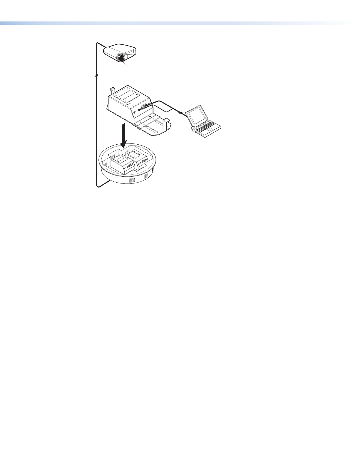
Projector
Extron
Extender AKM MAAP
Line Driver
EXTENDER AKM MAAP
COMPUTER IN
AUDIO IN
Laptop
Figure 12. An Extender AKM MAAP Application
Extender Series • Installation 17
Page 26
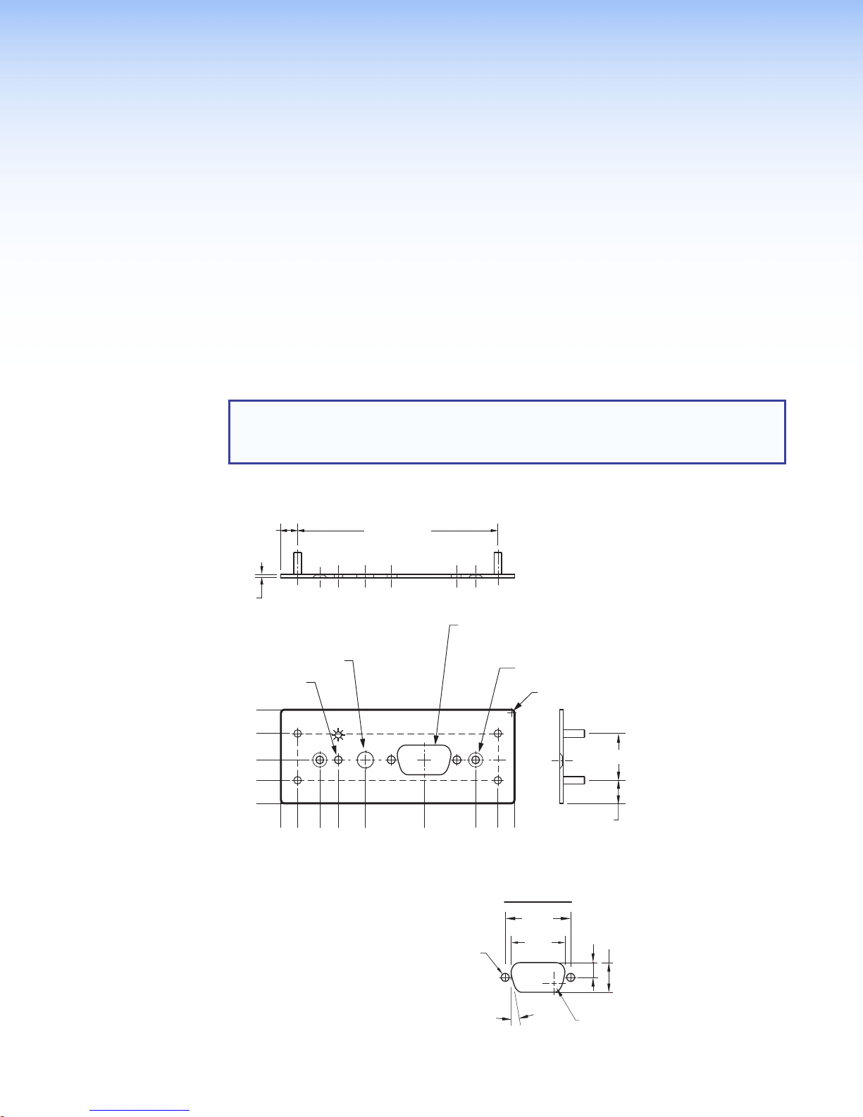
Reference Information
(TYP)
0.700 (REF)
0.250”
0.050”
(REF)
This section of the guide includes the following reference items:
• Dimensions
• Cut-out Templates
To read product specifications, visit the ExtenderSeries product pages at
www.extron.com.
Dimensions
NOTES:
• The drawings in this section are not full size. Do not scale.
• All dimensions are given in inches.
Extender AAP and Extender AAP EX Dimensions
(REF)
3.000” (REF)
ø 0.125” THRU
1.400
1.045
0.650
0.345
0.000
ø 0.250” THRU
0.583
0.250
0.000
AUDIO IN
0.860
1.266
COMPUTER IN
2.125
ø 0.125 THRU
DETAIL A
(2 PLCS)
ø 0.125 THRU WITH
ø 0.220 X 100° C'SINK
NEAR SIDE (2 PLACES)
2.917
3.250
3.500
DETAIL A
0.984
0.806
R 0.040 (TYP)
0.345
(REF)
0.224
0.449
10°
(2 PLCS)
R 0.132“
Extender Series • Reference Information 18
Page 27

Extender WM Dimensions
4.500
3.890
0.610
1.107
1.550
2.010
2.570
3.392
0.000
ø 0.156 THRU WITH
ø 0.562 C'BORE
ø 0.290 X 82° C'SINK
(2 PLACES)
0.000
1.395
AUDIO IN
COMPUTER IN
EXTENDER WM
2.790
ø 0.125 THRU
ø 0.330 THRU
WITH
0.070 DEEP
Extender Series • Reference Information 19
Page 28

Extender WM AAP Dimensions
ø 0.156" THRU WITH
ø 0.330"
2
(TYP)
0.000
3.000"
Ø 0.220" X 100°
Ø 0.250" THRU
Ø 0.125" THRU
ø 0.125" THRU
THRU WITH
ø 0.562" C'BORE
0.070" DEEP
A
DETAIL B
ø 0.125" THRU WITH
ø 0.220" X 100°
C'SINK
NEAR SIDE
(2 PLACES)
R 0.070" TOP EDGE
(ALL AROUND)
ø 0.290" X 82° C'SINK
(4 PLACES MARKED C)
4.500
3.890
3.393
2.950
2.490
1.930
1.550
1.107
0.610
0.000 0.000"
0.000
0.060"
0.060"
CC
AUDIO IN
COMPUTER IN
CC
2.780
1.388
2.650
2.390
SECTION A–A
3.520
+0.010
-
0.000
EXTENDER WM AAP
5.013
5.520
5.650
6.400
0.050
4.500"
R 0.240"
(TYP)
3.300"
2.600"
1.900"
ø 0.170"
(8 PLCS)
1.200"
+0.003
-
0.000
R 0.070"
TOP EDGE
(ALL AROUND)
A
ø 0.125 THRU
ø 0.250 x 0.50
DEEP (2 PLCS)
10° (2 PLCS)
2.810
C'BORE
+0.010
-
0.000
0.845"
DETAIL B
0.984
0.806
0.100
THK.
(REF)
0.224
0.449
R 0.13
Extender WM AUS Dimensions
AUDIO IN
COMPUTER IN
EXTENDER WM AUS
"
0.000
0.671
1.157
1.434
1.840
2.228
2X Ø 0.125" THRU
3.493
3.979
4.650
Extender Series • Reference Information 20
Page 29

Extender MK Dimensions
0.449"
R 0.070"
0.060
#4-40
THREADED
DETAIL A
0.449"
TOP EDGE
(ALL AROUND)
0.060"
0.100"
THICK
ø 0.125" THRU
R 0.040" (TYP)
3.380
1.690
0.000
0.474
0.000
C'BORE 2.780 x 1.070 x 0.050 DEEP
ø 0.250"
THRU
1.681
1.460
(C’BORE FAR SIDE)
Extender AKM UK Dimensions
5X 1.643"
0.272"
0.457"
1.958
AUDIO IN
2.365
+0.003
-0.000
COMPUTER IN
3.898"
3.244
DETAIL A
EXTENDER MK
4.240
4.017
ø 0.125" THRU WITH
ø 0.220" X 100° C'SINK NEAR SIDE (2 PLCS)
DETAIL A
ø 0.125"
THRU
(2 PLCS)
(2 PLCS)
ø 0.156" THRU WITH
ø 0.290" X 100° C'SINK
(2 PLCS)
5.700
5.224
6.638"
7.613"
7.428"
0.984"
0.806
10°
0.224"
3.000"
2.667"
1.895"
4X 1.500"
1.016"
0.610"
0.325"
0.000
0.590"
"
2X Ø.125" THRU
w Ø.272" x 100°
Ø 0.250"
0.000"
THRU
MARKED B
B
B
Ø 0.125"
THRU
(7.156)
2X 2.200"
+0.020"
2.110
-0.000"
Ø 0.174" THRU
2X 0.800"
0.445"
3X 3.768"
6X Ø 0.180"
THRU
R 0.030"
(TYP)
3X 6.768"
7.156"
4X R 0.060"
ø 0.125 THRU
(2 PLCS)
(2 PLCS)
DETAIL A
ROTATED 90° C.W.
0.984
0.806
10°
0.224"
"
Extender Series • Reference Information 21
Page 30

Extender AKM MAAP Dimensions
4X R 0.125"
2X R 0.062
2X 2.350
2X 0.650
+0.000
2X R
2X 0.06" X 45°
3.000
-0.015
1.975
1.750
1.250
1.025
1.675
0.275
0.000
5.375
5.750
2X 5.713
6.020±020
3X 5.000
2X 5.249
3.100
A
A
2X 1.050
2X 2.250"
2X Ø 0.150"
THRU
2X 0.750"
0.000"
0.000
2X 2.250
(0.075")
Extender Series • Reference Information 22
Page 31

Extender D Dimensions
2X EXTRUSION FO
0.905"
1.290"
0.000"
7X 0.645"
1.290"
2X 0.062” X 45°
0.333”
0.625"
0.223”
2X Ø 0.106" THRU
R
#6-32 SCREW
TAPPING
2.610"
2.005"
1.545"
0.984"
0.000"
BOTH SIDES
0.399”
2X 0.111"
Ø 0.132" THRU
Ø 0.258" THRU
2X 0.125"
(0.223")
0.359
0.111"
0.330"
Extender Series • Reference Information 23
Page 32

Cut-out Templates
(11.43 cm)
or
Cut-Out Template for the Extron
Please verify dimensions prior to cutting.
NOTE: Always check and use the dimensions given in this guide
Extender WM Template
Extender WM
2.79"
(7.09 cm)
4.50"
2.24"
(105 cm)
4.13"
(57 cm)
SURFACE
CUT-OUT
AREA FOR
MOUNTING
TEMPLATE IS FULL SIZE.
Top Panel
Location of
Extender AAP
Circuit Board
Cut Out Line f
Installing the
Electrical Box
Extender Series • Reference Information 24
Page 33

Extender WM AAP Template
(16.3 cm)
Extender WM AAP
Cut-Out Template for the Extron
4.5” (11.43 cm)
Location of Extender AAP Circuit Board
3.86” (9.80 cm)
6.4"
5.73”
Top Panel
(14.55 cm)
SURFACE
CUT-OUT AREA
FOR MOUNTING
Cut Out Line for
Installing the
Electrical Box
TEMPLATE IS FULL SIZE.
Please verify dimensions prior to cutting.
Extender Series • Reference Information 25
Page 34

Extender MK Template
(14.48 cm)
anel
Cut-Out Template for the Extron
Extender MK
3.38"
(8.56 cm)
To p
P
1.85"
(4.70 cm)
5.70"
2.91"
(7.40 cm)
SURFACE
CUT-OUT AREA
FOR MOUNTING
TEMPLATE IS FULL SIZE.
Please verify dimensions prior to cutting.
Location of
Extender
Circuit Board
To install an
Extender MK
directly into
furniture, cut
along this line.
Extender Series • Reference Information 26
Page 35

Extender WM AUS Template
(11.81 cm)
Cut-out Template for the Extron
the Extender
Please verify dimensions prior to cutting.
Extender WM AUS
3.00"
(7.62 cm)
Top Panel
1.85"
(4.70 cm)
4.65"
2.91"
(7.40 cm)
SURFACE
CUT-OUT AREA
FOR MOUNTING
TEMPLATE IS FULL SIZE.
Location of
Extender
Circuit Board
To install
WM AUS
directly into
furniture,
cut along
this line.
Extender Series • Reference Information 27
Page 36

Extron Warranty
Extron Electronics warrants this product against defects in materials and workmanship for a period of three years
from the date of purchase. In the event of malfunction during the warranty period attributable directly to faulty
workmanship and/or materials, Extron Electronics will, at its option, repair or replace said products or components,
to whatever extent it shall deem necessary to restore said product to proper operating condition, provided that it is
returned within the warranty period, with proof of purchase and description of malfunction to:
USA, Canada, South America,
and Central America:
Extron Electronics
1230 South Lewis Street
Anaheim, CA 92805
U.S.A.
Europe and Africa:
Extron Europe
Hanzeboulevard 10
3825 PH Amersfoort
The Netherlands
Asia:
Extron Asia Pte Ltd
135 Joo Seng Road, #04-01
PM Industrial Bldg.
Singapore 368363
Singapore
This Limited Warranty does not apply if the fault has been caused by misuse, improper handling care, electrical
or mechanical abuse, abnormal operating conditions, or if modifications were made to the product that were not
authorized by Extron.
Japan:
Extron Electronics, Japan
Kyodo Building, 16 Ichibancho
Chiyoda-ku, Tokyo 102-0082
Japan
China:
Extron China
686 Ronghua Road
Songjiang District
Shanghai 201611
China
Middle East:
Extron Middle East
Dubai Airport Free Zone
F13, PO Box 293666
United Arab Emirates, Dubai
NOTE: If a product is defective, please call Extron and ask for an Application Engineer to receive an RA (Return
Authorization) number. This will begin the repair process.
USA: 714.491.1500 or 800.633.9876 Europe: 31.33.453.4040
Asia: 65.6383.4400 Japan: 81.3.3511.7655
Units must be returned insured, with shipping charges prepaid. If not insured, you assume the risk of loss or damage
during shipment. Returned units must include the serial number and a description of the problem, as well as the
name of the person to contact in case there are any questions.
Extron Electronics makes no further warranties either expressed or implied with respect to the product and its quality,
performance, merchantability, or fitness for any particular use. In no event will Extron Electronics be liable for direct,
indirect, or consequential damages resulting from any defect in this product even if Extron Electronics has been
advised of such damage.
Please note that laws vary from state to state and country to country, and that some provisions of this warranty may
not apply to you.
Worldwide Headquarters: Extron USA West, 1025 E. Ball Road, Anaheim, CA 92905, 800.633.9876
 Loading...