

Page 1

eLink 100
HDMI Wireless Extender
User Guide
HDMI
68-2662-01 Rev. C
12 14
Page 2

Safety Instructions
Safety Instructions • English
WARNING: This symbol, , when used on the product, is intended to
alert the user of the presence of uninsulated dangerous voltage within the
product’s enclosure that may present a risk of electric shock.
ATTENTION: This symbol, , when used on the product, is intended
to alert the user of important operating and maintenance (servicing)
instructions in the literature provided with the equipment.
For information on safety guidelines, regulatory compliances, EMI/EMF
compatibility, accessibility, and related topics, see the Extron Safety and
Regulatory Compliance Guide, part number 68-290-01, on the Extron website,
www.extron.com.
Instructions de sécurité • Français
AVERTISSEMENT : Ce pictogramme, , lorsqu’il est utilisé sur le
produit, signale à l’utilisateur la présence à l’intérieur du boîtier du produit
d’une tension électrique dangereuse susceptible de provoquer un choc
électrique.
ATTENTION : Ce pictogramme, , lorsqu’il est utilisé sur le produit,
signale à l’utilisateur des instructions d’utilisation ou de maintenance
importantes qui se trouvent dans la documentation fournie avec le
matériel.
Pour en savoir plus sur les règles de sécurité, la conformité à la réglementation,
la compatibilité EMI/EMF, l’accessibilité, et autres sujets connexes, lisez les
informations de sécurité et de conformité Extron, réf. 68-290-01, sur le site
Extron, www.extron.com.
Sicherheitsanweisungen • Deutsch
WARNUNG: Dieses Symbol auf dem Produkt soll den Benutzer
darauf aufmerksam machen, dass im Inneren des Gehäuses dieses
Produktes gefährliche Spannungen herrschen, die nicht isoliert sind
und die einen elektrischen Schlag verursachen können.
Инструкция по технике безопасности • Русский
ПРЕДУПРЕЖДЕНИЕ: Данный символ, , если указан
на продукте, предупреждает пользователя о наличии
неизолированного опасного напряжения внутри корпуса
продукта, которое может привести к поражению
электрическим током.
ВНИМАНИЕ: Данный символ, , если указан на продукте,
предупреждает пользователя о наличии важных инструкций
по эксплуатации и обслуживанию в руководстве,
прилагаемом к данному оборудованию.
Для получения информации о правилах техники безопасности,
соблюдении нормативных требований, электромагнитной
совместимости (ЭМП/ЭДС), возможности доступа и других
вопросах см. руководство по безопасности и соблюдению
нормативных требований Extron на сайте Extron: www.extron.com,
номер по каталогу - 68-290-01.
Chinese Simplified(简体中文)
警告: 产品上的这个标志意在警告用户该产品机壳内有暴露的危险 电压,
有触电危险。
注意: 产品上的这个标志意在提示用户设备随附的用户手册中有
重要的操作和维护(维修)说明。
关于我们产品的安全指南、遵循的规范、EMI/EMF 的兼容性、无障碍
使用的特性等相关内容,敬请访问 Extron 网站 www.extron.com,参见
Extron 安全规范指南,产品编号 68-290-01。
Chinese Traditional( )
警告: 若產品上使用此符號,是為了提醒使 用者,產品機 殼內存在著
可能會導致觸電之風險的未絕緣危險電壓。
VORSICHT: Dieses Symbol auf dem Produkt soll dem Benutzer in der
im Lieferumfang enthaltenen Dokumentation besonders wichtige Hinweise
zur Bedienung und Wartung (Instandhaltung) geben.
Weitere Informationen über die Sicherheitsrichtlinien, Produkthandhabung,
EMI/EMF-Kompatibilität, Zugänglichkeit und verwandte Themen finden Sie in
den Extron-Richtlinien für Sicherheit und Handhabung (Artikelnummer
68-290-01) auf der Extron-Website, www.extron.com.
Instrucciones de seguridad • Español
ADVERTENCIA: Este símbolo, , cuando se utiliza en el producto,
avisa al usuario de la presencia de voltaje peligroso sin aislar dentro del
producto, lo que puede representar un riesgo de descarga eléctrica.
ATENCIÓN: Este símbolo, , cuando se utiliza en el producto, avisa
al usuario de la presencia de importantes instrucciones de uso y
mantenimiento recogidas en la documentación proporcionada con el
equipo.
Para obtener información sobre directrices de seguridad, cumplimiento
de normativas, compatibilidad electromagnética, accesibilidad y temas
relacionados, consulte la Guía de cumplimiento de normativas y seguridad de
Extron, referencia 68-290-01, en el sitio Web de Extron, www.extron.com.
注意 若產品上使用此符號,是為了提醒使用者,設備隨附的用戶手冊中有重
要的操作和維護(維修)説明。
有關安全性指導方針、法規遵守、EMI/EMF 相容性、存取範圍和相關主題的詳細資
訊,請瀏覽 Extron 網站:www.extron.com,然後參閱《Extron 安全性與法規
遵守手冊》,準則編號 68-290-01。
Japanese
警告: この記号 が製品上に表示されている場合は、筐体内に絶縁されて
いない高電圧が流れ、感電の危険があることを示しています。
注意: この記号 が製品上に表示されている場合は、本機の取扱説明書
に 記載さ れて いる重 要な操 作 と保 守 ( 整 備)の 指 示につ いてユーザ ー の 注
意を喚起するものです。
安全上のご注意、法規厳守、EMI/EMF適合性、その他の関連項目に
つ い て は 、エ ク ストロン の ウェ ブ サ イト www.extron.com よ り 『 Extron Safety
and Regulatory Compliance Guide』 ( P/N 68-290-01) をご覧ください。
Korean
경고: 이 기호 가 제품에 사용될 경우, 제품의 인클로저 내에 있는
접지되지 않은 위험한 전류로 인해 사용자가 감전될 위험이 있음을
경고합니다.
주의: 이 기호 가 제품에 사용될 경우, 장비와 함께 제공된 책자에 나와
있는 주요 운영 및 유지보수(정비) 지침을 경고합니다.
안전 가이드라인, 규제 준수, EMI/EMF 호환성, 접근성, 그리고 관련 항목에
대한 자세한 내용은 Extron 웹 사이트(www.extron.com)의 Extron 안전 및
규제 준수 안내서, 68-290-01 조항을 참조하십시오.
Page 3

FCC Class B Notice
NOTE: This device complies with part 15 of the FCC rules. Operation is subject to the following
This equipment has been tested and found to comply with the limits for a Class B digital device,
pursuant to part15 of the FCC rules. These limits provide reasonable protection against harmful
interference in a residential installation. This equipment generates, uses, and can radiate radio
frequency energy and, if not installed and used in accordance with the instructions, may cause harmful
interference to radio communications. There is no guarantee that interference will not occur. If this
equipment does cause interference to radio or television reception, which can be determined by
turning the equipment off and on, you are encouraged to try to correct the interference by one or more
of the following measures:
• Reorient or relocate the receiving antenna.
• Increase the separation between the equipment and receiver.
• Connect the equipment into an outlet on a circuit different from that to which the receiver is
• Consult the dealer or an experienced radio/TV technician for help.
In order to maintain compliance with FCC regulations, shielded cables must be used with this
equipment. Operation with non-approved equipment or unshielded cables is likely to result in
interference to radio and TV reception. The user is cautioned that changes and modifications made to
the equipment without the approval of the manufacturer could void the user’s authority to operate this
equipment.
This Class B digital apparatus complies with Canadian ICES-003.
Cet appareil numérique de la classe B est conforme à la norme NMB-003 du Canada.
two conditions: (1) This device may not cause harmful interference, and (2) This device must
accept any interference received, including interference that may cause undesired operation.
connected.
ATTENTION:
• This equipment complies with FCC radiation exposure limits set forth for an
uncontrolled environment. This equipment should be installed and operated with
minimum distance 20 cm (7.9 inches) between the radiator and your body.
• Cet équipement est conforme aux limites de radiation de la FCC établies pour un
environnement non géré. Il doit être installé et contrôlé à une distance minimale de
20 cm (7,9 pouces) entre le radiateur et votre corps.
NOTE: For more information on safety guidelines, regulatory compliances,
EMI/EMF compatibility, accessibility, and related topics see the “Extron Safety and
Regulatory Compliance Guide” on the Extron website.
Page 4

Conventions Used in this Guide
Notifications
The following notifications are used in this guide:
CAUTION: Risk of minor personal injury.
ATTENTION : Risque de blessuremineure.
ATTENTION:
• Risk of property damage.
• Risque de dommages matériels.
NOTE: A note draws attention to important information.
Specifications Availability
Product specifications are available on the Extron website, www.extron.com.
Copyright
© 2014 Extron Electronics. All rights reserved.
Trademarks
All trademarks mentioned in this guide are the properties of their respective owners.
The following registered trademarks®, registered service marks
RGBSystems, Inc. or Extron Electronics:
Registered Trademarks
AVTrac, Cable Cubby, CrossPoint, eBUS, EDID Manager, EDID Minder, Extron, Flat Field, GlobalViewer, Hideaway, Inline, IPIntercom,
IPLink, Key Minder, LockIt, MediaLink, PlenumVault, PoleVault, PowerCage, PURE3, Quantum, SoundField, SpeedMount, SpeedSwitch,
SystemINTEGRATOR, TeamWork, TouchLink, V-Lock, VersaTools, VN-Matrix, VoiceLift, WallVault, WindoWall, XTP, and XTPSystems
Registered Service Mark
AAP, AFL (Accu-RateFrameLock), ADSP(Advanced Digital Sync Processing), Auto-Image, CableCover, CDRS(ClassDRippleSuppression),
DDSP (Digital Display Sync Processing), DMI (DynamicMotionInterpolation), DriverConfigurator, DSPConfigurator, DSVP(Digital Sync
Validation Processing), EQIP, FastBite, FOXBOX, Global Configurator, IP Intercom HelpDesk, LinkLicense, MAAP, MicroDigital, ProDSP,
QS-FPC(QuickSwitch Front Panel Controller), Scope-Trigger, ShareLink, SIS, Simple Instruction Set, Skew-Free, SpeedNav,
Triple-Action Switching, XTRA, ZipCaddy, ZipClip
(SM)
: S3 Service Support Solutions
Trademarks (™
(SM)
, and trademarks
(®)
)
(TM)
are the property of
Page 5

Contents
Introduction............................................................ 1
About this Guide ................................................. 1
About the eLink 100 Transmitter and Receiver .... 1
Features ............................................................. 2
Application Diagram ........................................... 3
Installation .............................................................. 4
Before Getting Started ........................................ 4
Front and Side Panel Features and
Connections ...................................................... 5
Transmitter Connections ................................. 5
Receiver Connections ..................................... 6
Installing the Plug on the Power Supply .............. 7
The eLink 100 On-screen Display ....................... 8
Top Panel Features and Functions ...................... 8
Transmitter Buttons and LEDs ........................ 8
Receiver Buttons and LEDs ............................ 9
Operation .............................................................. 10
Operating Modes .............................................. 10
Registering the Transmitter with the Receiver .... 10
Registering Using the Remote Control .......... 10
Registering Using the Register Buttons ......... 11
Registering an Additional Receiver ................ 11
Using the Remote Control and the OSD
Menus ............................................................. 12
Remote Control Buttons ............................... 12
Using the Setup Menu .................................. 13
Reference Information ...................................... 15
Mounting the Transmitter and Receiver ............. 15
Best Practices for eLink 100 Mounting
Locations..................................................... 17
Resolutions and Rates ...................................... 18
Operating Frequencies ..................................... 19
Troubleshooting ................................................ 20
veLink 100 HDMI Transmitter and Receiver • Contents
Page 6

eLink 100 HDMI Transmitter and Receiver • Contents vi
Page 7

Introduction
• About this Guide
• About the eLink 100 Transmitter and Receiver
• Features
• Application Diagram
About this Guide
This guide describes how to install, operate, and configure the Extron eLink 100 wireless
extender for High Definition Multimedia Interface (HDMI) signals. The eLink 100 extender
consists of the eLink 100 T transmitter and the eLink 100 R receiver (sold separately).
About the eLink 100 Transmitter and Receiver
The eLink 100 transmitter and receiver pair uses multi-input and multi-output (MIMO)
wireless communication technology to transmit HDMI video and multi-channel embedded
audio. This HDCP-compliant extender can send computer video resolutions up to
1920x1080, including HDTV 1080p @ 60 Hz, with less than 1 ms required to process the
video signal (latency). AES-128 encryption provides a secure link to send signals up to
100 feet (30 meters).
The eLink 100 T transmitter uses the 5 GHz spectrum to transmit signals. In addition to
point-to-point applications, one transmitter can be linked with up to four eLink 100 R
receivers, allowing a single source such as a digital signage player to support multiple
displays.
The transmitter and receiver are wirelessly compatible only with each other, but they can
wirelessly extend any Extron product that has HDMI connectivity, including switchers and
scalers. The transmitter can be connected to any Extron HDMI output with a signal up to
1080p @ 60 Hz. The receiver can be connected to any Extron HDMI input.
NOTE: If using the eLink 100 as an extender to a switcher output, select a switcher with
an integrated scaler or signal processor for fastest switch times (see
www.extron.com for switcher part numbers).
The eLink 100 is ideal for use in professional AV environments such as presentation spaces,
rental and staging, and digital signage.
eLink 100 HDMI Transmitter and Receiver • Introduction 1
Page 8

Features
• Input: HDMI connector on eLink 100 T transmitter
Output: HDMI connector on eLink 100 R receiver
• Transmits HDMI video and multi-channel audio signals wirelessly up to
100 feet (30 meters) in professional AV environments.
• Transmission through common obstacles — The eLink 100 wireless extender
works in the 5 GHz spectrum to allow for broad coverage and transmission through
walls and furniture. Line-of-sight is not required but can maximize range.
• Resolutions and rates — Supports computer video up to 1920x1080, including
HDTV 1080p @ 60 Hz (see the Resolutions and Rates table on page 18).
• On-screen display (OSD) — The OSD provides an interface for simplified setup and
configuration.
• IR remote control — The eLink IR remote control, included with the receiver, enables
use of the OSD on the output screen for configuration and setup.
• Power supplies — Each unit includes an external 5 VDC power supply, which accepts
100 to 240 VAC, 50-60 Hz input. A DC-to-USB adapter is also provided with the
receiver, enabling the power supply to power the receiver through its USB port.
• AES 128 encryption — Supports Advanced Encryption Standard (AES) 128 data
encryption standard.
• HDMI features — Supported HDMI specification features include data rates up to
6.75 Gbps, Deep Color up to 12-bit, 3D, and multi-channel audio formats.
• HDCP compliant
• Ultra-low latency — Less than one millisecond of latency in transmission of video and
audio signals
• Dynamic Frequency Selection (DFS) —
• Actively monitors the radio frequency (RF) spectrum to select the most appropriate
frequencies, and prevents interference from other devices operating in the
spectrum.
• Takes advantage of DFS frequencies that are reserved for radar and weather
purposes (see the Operating Frequencies table on page 19 for more information).
• Embedded audio — Compatible with a broad range of multi-channel audio signals,
providing reliable operation with HDMI devices and surround sound systems.
• MIMO (multi-input and multi-output) — MIMO technology ensures that wireless
connections are stable and function in environments with multipath signals.
• Wireless transmission to as many as four receivers — The transmitter can support
up to four receivers, allowing a single source such as a digital signage player to support
multiple displays.
eLink 100 HDMI Transmitter and Receiver • Introduction 2
Page 9

Application Diagram
Display
esc
F1 F2 F3 F4 F5 F6 F7 F8 F9 F10F11F12 F13 F14 F15 F16 F17 F18F19
~
!1@2#3$4%5^6&7*8(9)
`
QWERTYUIOP
tab
ASDFGHJ
caps lock
ZXCVBNM
shift
alt
control
Document
Camera
Laptop
option command
100-240V ~ 50/60 Hz
-- A MAX
Extron
IN1606
Scaling Presentation
Switcher
_
+
-
=
0
[
“‘:
KL
;
<,>.?
/
command option control
HDMI with
Embedded
Audio
S-video
Audio
VGA
1
CONFIGURABLE
2
WiFi
1234
PC
page
fn home clear
=/
*
up
delete
|\}]{
page
-
enddelete
7
9
8
down
+
6
5
4
return
3
2
1
shift
0.
enter
DisplayPort
to HDMI
Adapter
Audio
INPUTS OUTPUTSAUDIO INPUTSOUTPUTS REMOTE
5
3
HDMI
HDMI
6
4
Laptop
HDMI with
Embedded
Audio
STANDBY/ON
Extron
eLink 100 T
IN1606
Extron
TLP 1000TV
10" Ta bletop
TouchLink
Touchpanel
Blu-ray Player
PQLS HDMI OPEN/CLOSE FL OFF
HDMI with
Embedded
Audio
Microphones
1 and 2
USB
A
HDMI
B
HDMI IN
IR OUT
L1
L3
L5
R
R
L2
L4
L6
R
R
Wireless HDMI
Transmitter
Wireless up to 100' (30 m)
R
R
MIC/LINE
+48V
+48V
Ethernet
AudioAudio
12
1
VARIABLE
2
LR
TCP/IP
Network
Ethernet
LAN
RESET
100-240V 50-60Hz
COM1
COM2
COM3
TxRx GGGG
TxRx
TxRx
+-+-
SWITCHED 12VDC
40W MAX TOTAL
COM4
COM5
COM6
3 4
TxRx GGGG
TxRx
TxRx
+-+-
5A MAX
Extron
IPCP 505
Control Processor
RS-232
RS-232
Tx Rx
G
Ethernet
COM7
2
3
1
SGSG
SGSG
RTS CTS
TxRx
IR/SERIAL
COM8
5
6 7
SGSG
SGSG
RTS CTS
TxRx
4 1 21 2 3 4
8 5 6 7 8
LAN
RELAY
FLEX I/O
1234G
Extron
eLink 100 R
Wireless HDMI
Receiver
HDMI with
Embedded
Audio
HDMI
5V
1.5A MAX
HDMI OUT
POWER
Figure 1. Example of an eLink 100 Transmitter and Receiver Application
eLink 100 HDMI Transmitter and Receiver • Introduction 3
Page 10

Installation
This section provides instructions for installing the eLink 100 extender, including:
• Before Getting Started
• Front and Side Panel Features and Connections
• Installing the Plug on the Power Supply
• The eLink 100 On-Screen Display
• Top Panel Features and Functions
Before Getting Started
If mounting is required before cabling and setting up the eLink 100 units, see Mounting the
Transmitter and Receiver on page 15 for mounting instructions.
ATTENTION:
• Installation and service must be performed by authorized personnel only.
• L’installation et l’entretien doivent être effectués par le personnel autorisé
uniquement.
• These units are not suitable for use in air handling spaces.
• Ces unites ne sont pas appropriées pour une utilisation dans les espaces
d’aération.
NOTE: For best performance:
• Ensure that the installation location is suitable for good signal transmission.
• For optimal signal range, avoid obstructions, such as walls, furniture or rack
enclosures, between the transmitter and receiver locations. Denser wall materials
can cause signal reduction.
• Maximum transmission distance is 100 feet (30 meters) with a clear line-of-sight.
• Up to four transmitter units can operate in the same room or environment. If
a maximum of four transmitters is reached, the next group of units should be
separated to prevent interference (see Best Practices for eLink 100 Mounting
Locations on page 17).
• Maintain a distance of at least 6.5 feet (2 meters) between multiple eLink
transmitters or multiple eLink receivers. Be mindful of units located beyond walls in
adjacent rooms.
• Maintain a distance of at least 6.5 feet (2 meters) between the eLink 100 units and
other 5 GHz RF devices. RF products can cause interference or traffic in the 5 GHz
frequency band. Monitor the 5 GHz frequency band and plan systems to avoid
traffic.
• Do not block the eLink 100 air ventilation openings and ensure proper air ventilation
around the units.
• Be careful when handling the eLink 100 units as they become hot during operation.
• Do not install above ceiling tiles. The eLink 100 is not UL Listed for use in plenum
air handling spaces.
eLink 100 HDMI Transmitter and Receiver • Installation 4
Page 11
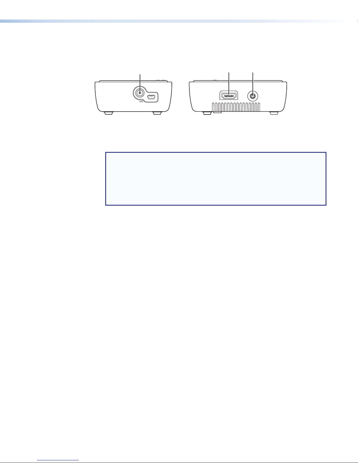
Front and Side Panel Features and Connections
Side Panel
Transmitter Connections
A
POWER
5V
1.5A MAX
Front Panel
SERVICE
B
HDMI IN
C
IR OUT
Figure 2. eLink 100 T Transmitter Side Panels
Power input connector — Plug the external 5 VDC power supply into this 5 V jack
A
to power the transmitter.
NOTES:
• Use only the power supply provided by Extron. See the Attention on page 7
for important information.
• The USB mini-B port to the right of this connector is reserved for use by Extron
service personnel.
• See Installing the Plug on the Power Supply on page 7 if a different power
supply plug is needed for your location.
HDMI In connector — Connect an HDMI cable between this port and the HDMI
B
output port of the digital video source device.
IR Out connector — (Optional) Connect the tip-ring-sleeve end of the provided IR
C
emitter to this IR Out connector. Use the included double-sided adhesive tape to attach
the head of the IR emitter directly over the IR receiver window of the source device.
IR remote signals are passed from the receiver to the IR Out connector on the
transmitter. This feature allows the user to point the remote control toward the receiver
(by the display) instead of the source device, should the source device be in a different
location.
eLink 100 HDMI Transmitter and Receiver • Installation 5
Page 12

Receiver Connections
Receiver.
3.25 inches
Figure 3. eLink 100 R Receiver Side Panel
IR sensor — Receives IR commands from the included IR remote control unit and the
A
IR remote of the source device.
NOTES:
• The IR sensor is compatible only with 38 kHz IR carrier frequency. See the
specifications for the IR remote of the source device or contact the device
manufacturer to verify the compatibility of the IR remote frequency.
• Make sure that the receiver IR sensor faces forward if using a source device IR
remote to pass signals back to the transmitter. Wall mounting or concealing the
receiver causes the IR sensor to be unreachable.
USB Power connector — Connect the USB end of the provided 5 V jack-to-USB
B
adapter to this USB mini-B connector. Connect the other end of the adapter to the
provided 5 VDC power supply.
BB
POWER
5V
1.5A MAX
Back Panel
HDMI
HDMI OUT
NOTE: Use only the power supply provided by Extron. See the Attention on the
next page for important information.
To Power Supply
NOTE: Snap the included
ferrite bead onto the
To USB Power
Connector on
(8.25 cm)
power supply cable at a
distance of 3.25 inches
(8.25 cm) from the end
of the DC connector.
HDMI Out connector — Connect an HDMI cable between this port and the HDMI
C
input connector of the display device.
eLink 100 HDMI Transmitter and Receiver • Installation 6
Page 13

ATTENTION:
Europe
• This product is intended to be supplied by a Listed Power Unit marked “Class 2”
or “LPS,” rated 5 VDC, 2.6 A minimum. Always use a power supply supplied by
or specified by Extron. Use of an unauthorized power supply voids all regulatory
compliance certification and may cause damage to the supply and the end product.
• Ce produit est destiné à une utilisation avec une source d’alimentation listéeUL
avec l’appellation «Classe2» ou «LPS» et normée 5Vcc, 2,6A minimum.
Utilisez toujours les sources d’alimentation recommandées par Extron. L’utilisation
d’une source d’alimentation non autorisée annule toute conformité réglementaire
et peut endommager la source d’alimentation ainsi que le produit final.
• Unless otherwise stated, the AC/DC adapters are not suitable for use in air
handling spaces or in wall cavities.
• Sauf mention contraire, les adaptateurs AC/DC ne sont pas appropriés pour une
utilisation dans les espaces d’aération ou dans les cavités murales.
• The installation must always be in accordance with the applicable provisions of
National Electrical Code ANSI/NFPA 70, article 725 and the Canadian Electrical
Code part 1, section 16. The power supply shall not be permanently fixed to a
building structure or similar structure.
• Cette installation doit toujours être en accord avec les mesures qui s’applique
au National Electrical Code ANSI/NFPA70, article725, et au Canadian Electrical
Code, partie1, section16. La source d’alimentation ne devra pas être fixée de
façon permanente à une structure de bâtiment ou à une structure similaire.
Installing the Plug on the Power Supply
Each eLink 100 power supply kit contains a set of four plugs for use in different outlet types:
US
Figure 4. Included Power Supply Plugs
Select the appropriate plug for your location and follow the instructions below to install it on
the power supply.
1. Slide the tab at the top of the power plug under the top edge of the recess in the power
supply (see figure 5, 1).
2. Press down on the plug until it snaps into place in the power supply recess (2).
UK
11
Australia
22
Figure 5. Inserting the Plug Into the eLink 100 Power Supply
eLink 100 HDMI Transmitter and Receiver • Installation 7
Page 14

To remove a power plug from the power supply, press downward on the latch (marked
with an arrow) below the plug recess.
The eLink 100 On-screen Display
When the receiver is powered and connected to the display device, the On-screen Display
(OSD) appears. See the Operation section on page 10 for instructions on using the OSD.
Top Panel Features and Functions
The eLink 100 controls and indicators are located on the top panels of the transmitter and
receiver.
Transmitter Buttons and LEDs
Extron
eLINK 100 T
LINK
VIDEO
POWER
AA
BB
CC
DD
REGISTER
RESET
Figure 6. eLink 100 T Transmitter Top Panel
Link LED — Blinks while the receiver is searching for a link to register with the
A
transmitter (see Registering the Transmitter with the Receiver on page 10). When a
link has been made, this LED lights steadily.
Video LED — If the transmitter is registered with the receiver, this LED lights steadily
B
when a valid source video format is detected and transmitted (see Resolutions and
Rates table on page 18).
Power LED — Lights steadily while power is connected to the transmitter.
C
Register button — Hold this button after starting the registration process on the
D
receiver (see Registering the Transmitter with the Receiver on page 10).
Reset button — Press this button to reset the transmitter, if needed for troubleshooting
E
(see Troubleshooting on page 20).
E
E
eLink 100 HDMI Transmitter and Receiver • Installation 8
Page 15

Receiver Buttons and LEDs
Extron
eLINK 100 R
POWER
REGISTER
LINK
VIDEO
Figure 7. eLink 100 R Receiver Top Panel
Power button — Hold this button to power on the eLink 100 receiver. The blue LED
A
behind this button lights to indicate that power is on.
NOTE: By default, the blue LED in this button lights and the receiver is powered on
when power is connected to the unit.
Register button — Press this button to initiate the registration process between the
B
receiver and transmitter (see Registering the Transmitter with the Receiver on
the next page).
Link LED — This blue LED blinks while the receiver is searching for a transmitter (see
C
Registering the Transmitter with the Receiver). When a link has been made, this
LED lights steadily.
Video LED — This blue LED lights steadily when the transmitter and receiver are linked.
D
AA
BB
CC
DD
eLink 100 HDMI Transmitter and Receiver • Installation 9
Page 16

Operation
This section describes the installation and the operation of the eLink 100 extender,
including:
• Operating Modes
• Registering the Transmitter with the Receiver
• Using the Remote Control and the OSD Menus
Operating Modes
The eLink 100 can operate in two modes:
• One transmitter linked up to one receiver.
NOTE: Up to four transmitter units can operate in the same room or environment.
• One transmitter linked with up to four receivers.
If a maximum of four transmitters is reached, the next group of units should be
separated to prevent interference (see Best Practices for eLink 100 Mounting
Locations on page 17).
NOTE: Maintain at least 6.5 feet (2 meters) between multiple eLink transmitters or
multiple eLink receivers. Be mindful of units located beyond walls in adjacent rooms.
To establish communication between the eLink 100 transmitter and receiver, the transmitter
must be registered with the receiver as explained below.
Registering the Transmitter with the Receiver
After registration is performed at the initial setup, the transmitter and receiver connect
automatically when booted. Registration is not required again unless the transmitter is
unregistered or removed from the receiver memory (see Unregistering a transmitter on
page 14).
The units can be registered using the eLink 100 remote control (provided) or using the
register buttons on the eLink 100 units.
Registering Using the Remote Control
NOTE: The remote control must be pointed at the IR sensor on the front panel of the
receiver (see figure 3, A, on page 6) from a distance of no more than 30 feet
(9.1 meters) and no more than 40º from center.
To register the transmitter with the receiver using the eLink 100 remote control:
1. Connect and apply power to the transmitter, input source, receiver, and output source.
NOTE: The registration process can be done without an input connected. In this
case, a message appears on the OSD, notifying you of a missing video source.
2. Press the Add button on the remote control (see figure 8, G, on page 12). The
following message appears on the OSD: Please Activate Registration on
Transmitter Unit.
eLink 100 HDMI Transmitter and Receiver • Operation 10
Page 17

3. Press and hold the Register button on the transmitter top panel until the following
message appears on the OSD: Adding transmitter name. Press OK to continue or
Exit to cancel
4. Press the OK button on the remote control (see figure 8, E, on page 12) to confirm.
The message Adding transmitter name... and a progress bar appear on the OSD
while the registration process is completing.
NOTE: Registration may take up to 60 seconds to complete. If the process is
delayed more than 60 seconds, cycle power on both units, then restart the
registration process.
When registration is complete, the message and progress bar disappear from the
display. The Link LED and the Video LED light steadily.
Registering Using the Register Buttons
To register the transmitter with a receiver without using the remote control:
1. Connect and apply power to the transmitter, input source, receiver, and output source.
NOTE: The registration process can be done without an input connected. In this
case, a message appears on the OSD, notifying you of a missing video source.
2. Press and hold the Register button on the receiver top panel until the following
message appears on the OSD: Please Activate Registration on Transmitter
Unit.
3. Press and hold the Register button on the transmitter top panel until the following
message appears on the OSD:
Adding transmitter name. Press OK to continue or Exit to cancel
4. Press the Register button on the receiver to confirm. The message Adding
transmitter name... and a progress bar appear on the OSD while the registration
process is completing.
NOTE: Registration may take up to 60 seconds to complete. If the process is
delayed more than 60 seconds, cycle power on both units, then restart the
registration process.
When registration is complete, the message and progress bar disappear from the
display. The Link LED and the Video LED light steadily.
Registering an Additional Receiver
To register an additional receiver with a transmitter:
1. Power down all receivers except the one you are registering.
2. Perform steps 2 through 4 above for your preferred method of registering the receiver
(using the remote control or using the register buttons).
3. When registration is complete, power on the other receivers. The video should be
displayed on all monitors.
eLink 100 HDMI Transmitter and Receiver • Operation 11
Page 18

Using the Remote Control and the OSD Menus
Select Video Source
Remote Control Buttons
Use the eLink 100 IR remote to control and navigate the OSD.
NOTE: The remote control must be pointed at the IR sensor on the front panel of the
receiver (see figure 3, A, on page 6) from a distance of no more than 30 feet
(9.1 meters) and no more than 40º from center.
CAUTION:
• Risk of explosion. Do not replace the battery with an incorrect type. Dispose of
used batteries according to the instructions.
• Risque d’explosion. Ne pas remplacer la pile par le mauvais type de pile.
Débarrassez-vous des piles usagées selon le mode d’emploi.
AA
MENU
DELETE
1
EXIT
OK
ADD
+
INPUT DEVICES
2
SOURCE
GUEST
3
BB
CC
DD
EE
FF
GG
HH
II
Menu
A
Exit
B
Source
C
Direction arrows
D
OK
E
Delete
F
Add
G
Guest (Not Used)
H
Input Devices buttons
I
(Not Used)
Figure 8. eLink 100 IR Remote Control
Menu — Displays the OSD Setup menu (see Using the Setup Menu on the next
A
page).
Exit — Returns to the previous menu. If the Setup menu is displayed, pressing this
B
button closes the OSD.
Source — Displays the Select Video Source menu, which lists the transmitter that is
C
registered to the receiver.
NOTE: The eLink 100 does not support applications with multiple transmitters to
one receiver. Only one transmitter should be used with as many as four receivers.
EXTRON112
Setup
Figure 9. Select Video Source
eLink 100 HDMI Transmitter and Receiver • Operation 12
Page 19

Direction arrows — The up and down arrow buttons scroll through menu items. The
Setup
D
right and left arrow buttons select characters when changing a video source name (see
Modifying a video source name on the next page).
NOTE: In the OSD screen, the yellow arrows on the right (see figure 9 on the
previous page) indicate that there are additional menu items to scroll through.
OK — Selects the menu item.
E
Delete — Displays the Choose Source to Remove submenu (see Unregistering a
F
transmitter on the next page). This menu may also be accessed from the Setup menu
by selecting Remove Video Source.
Add — Begins the registration process (see Registering the Transmitter with the
G
Receiver on page 10).
Using the Setup Menu
Add new Video Source
Remove Video Source
Modify Video Source Name
X
Disconnect Wireless Link
Figure 10. Setup Menu
The Setup menu enables you to set up the eLink 100 for operation. This menu includes the
following options:
• Add new Video Source — Select this option to register the transmitter with a receiver.
The message Please Activate Registration on Transmitter Unit appears.
See Registering the Transmitter with the Receiver for the rest of the registration
procedure.
• Remove Video Source — Select this option to unregister a transmitter (see
Unregistering a transmitter).
• Modify Video Source Name — Select this option to edit the name of an existing video
source (see Modifying a video source name on the next page).
• Disconnect Wireless Link — This appears on the menu only if the source is
displayed. Select this option to remove the connection between the source and the
display.
eLink 100 HDMI Transmitter and Receiver • Operation 13
Page 20

Unregistering a transmitter
Choose Source to Remove
To unregister a transmitter (remove a video source) from a receiver:
1. Power on the receiver.
2. From the Setup menu, select Remove Video Source. This opens the Choose Source
to Remove menu.
NOTE: Alternatively, you may press the Delete button on the remote control to
access this menu.
3. From the Choose Source to Remove menu, select the name of the source to be
unregistered.
EXTRON105
Figure 11. Choose Source to Remove OSD Menu
4. The message Removing transmitter name. Press OK to continue or Exit to
Cancel is displayed. Press the OK button again to delete the source. (To stop the
removal procedure, press the Exit button.)
NOTE: While the transmitter is being unregistered, the message Removing
transmitter name... is displayed. After approximately 30 seconds, the OSD
closes, indicating the source has been removed and the transmitter unregistered.
Modifying a video source name
To change the name of a video source:
1. Press the Menu button on the remote control to display the Setup menu.
2. From the Setup menu, select Modify Video Source Name.
3. From the Choose Source to Rename menu, select the source to be renamed. The
Rename Video Source Name screen appears, displaying only the name to be
changed.
4. Use the right and left arrow buttons on the remote control to move focus to the first
character that you want to change.
5. Press the up or down arrow buttons repeatedly until the desired replacement letter or
number is displayed.
• To step through the alphabet in ascending (A-to-Z) order, use the up arrow. The
down arrow moves through the alphabet in descending (Z-to-A) order.
• When you scroll through the characters in ascending order, the OSD displays the
letters of the uppercase alphabet, followed by the lowercase alphabet, then a
space, then digits 0 through 9, after which the display cycles back through, starting
with the uppercase letters. In descending order, this sequence is reversed.
6. Press the OK button. The Select a Video Source menu is displayed.
7. Select a source from the menu to display or press the Exit button to close the OSD.
eLink 100 HDMI Transmitter and Receiver • Operation 14
Page 21

Reference
Transmitter Template
Drill Mounting Holes
Information
This section includes the following reference information:
• Mounting the Transmitter and Receiver
• Resolutions and Rates
• Operating Frequencies
• Troubleshooting
Mounting the Transmitter and Receiver
ATTENTION:
• Installation and service must be performed by authorized personnel only.
• L’installation et l’entretien doivent être effectués par le personnel autorisé
uniquement.
NOTE: Before mounting, see Best Practices for eLink 100 Mounting Locations on
page 17.
The eLink 100 units can be placed on a table or mounted to a wall. For the transmitter and
receiver to communicate, they must be no further than 100 feet (30 meters) apart with a
clear line of sight.
To mount the transmitter or receiver to a wall or furniture:
1. Print and cut out the template for the unit to be mounted (cutout templates are available
at www.extron.com).
2. Tape the template to the wall in the desired location.
3. Drill pilot holes through each of the mounting hole centers on the template and into the
wall or furniture (see figure 12).
2.44 inches
(6.20 cm)
Drill
Mounting
Holes
1.87
inch
(4.75 cm)
Figure 12. Drill through the Center of the Two Mounting Hole Circles on the
Receiver Template
Transmitter or Receiver Template
eLink 100 HDMI Transmitter and Receiver • Reference Information 15
Page 22

4. Remove the template from the wall.
Wood Screw
(5 mm)
NOTE: Wall anchors may be required depending on wall material and stud
locations.
5. Insert two screws (see figure 13 for screw sizes) into the mounting holes
and tighten them until the screw heads protrude from the wall at the
following distances:
• Transmitter: approximately 3/16 inch (4.7 mm)
• Receiver: approximately 1/4 inch (6.35 mm)
NOTE: If necessary, adjust the screw protrusion so that the
eLink 100 unit is firmly secured on the wall or furniture surface.
Rx Tx
#8
#10
Pan Head
(4 mm)
Figure 13. Screw Sizes for the eLink 100 Transmitter (Tx) and Receiver (Rx)
NOTE: Choice of screw length depends on wall or furniture thickness.
6. Align the mounting holes on the back panel of the unit with the two screws protruding
from the wall (see figure 14).
Transmitter
Receiver
Figure 14. Mounting the eLink 100 Units
7. Slide the unit downward until both screws are seated in the narrow parts of the two
keyholes.
eLink 100 HDMI Transmitter and Receiver • Reference Information 16
Page 23

Best Practices for eLink 100 Mounting Locations
For transmitter-to-receiver applications (one transmitter linked with up to four
receivers):
• Ensure that the receivers are within a 100 foot (30 meter) radius of the transmitter with a
clear line-of-sight (see figure 15).
• Maintain a distance of at least 6.5 feet (2 meters) between the eLink 100 transmitter and
receiver.
R
100 feet
R
T
70 feet
R
R
Figure 15. One-to-Four Application
For applications involving several transmitter-receiver pairs:
• Up to four transmitter units can operate in the same room or environment. If a maximum
of four transmitters is reached, the next group of units should be separated to prevent
interference. Ensure that there is at least a 150 foot (45 meter) radius around the
outermost units in each group (see figure 16).
• Maintain a distance of at least 6.5 feet (2 meters) between individual eLink 100
transmitters and receivers. Be mindful of units located beyond walls in adjacent rooms.
150 feet
R
150 feet
T
R
T
Figure 16. Application with Groups of eLink 100 Transmitter-Receiver Pairs
R
T
eLink 100 HDMI Transmitter and Receiver • Reference Information 17
R
T
150 feet
150 feet
150 feet
150 feet
R
R
T
T
R
T
R
T
150 feet
150 feet
Page 24

Resolutions and Rates
The following tables list the video and 3D resolutions and rates that the eLink 100 supports.
Format
480i 720 (1440) x 480 X X
480p
576i 720 (1440) x 576
576p 720 x 576
720p 1280 x 720
1080i 1920 x 1080
1080p 1920 x 1080
VGA 640 x 480 X X
Resolution
50 Hz 60 Hz 72 Hz 23.98 Hz 24 Hz 25 Hz 59.94 Hz 29.97 Hz 30 Hz 70 Hz
640 x 480
720 x 480
X
X
X X
X X
X X
1366 x 768
1440 x 900
1400 x 1050
1600 x 900
1680 x 1050 X
X
X
X
X
X
X
X
X X X X X
Refresh Rates in Hz
X
X
X
X
SVGA 800 x 600 X X
XGA 1024 x 768 X
3D Rates
720p 1280 x 720
1080i 1920 x 1080
1080p 1920 x 1080
X X
X X
X X
X
X
X X
X X
X
X
X
X
X
X
eLink 100 HDMI Transmitter and Receiver • Reference Information 18
Page 25

Operating Frequencies
The eLink 100 uses DFS (Dynamic Frequency Selection) technology, which actively monitors
the RF spectrum to select the most appropriate frequencies. This prevents interference from
other devices operating in the 5 GHz spectrum.
For reference, the table below lists the operating frequencies and their range (DFS or
Non-DFS).
Frequency
(MHz)
5190
5230 X X X
5270
5310 X X X
5510 X X X
5550 X X X
5590 X X
5630 X
5670 X X X
5755
5795 X
NOTES:
• Up to four transmitter units can operate in the same room or environment. Each
transmitter unit occupies one of these frequencies.
• If a maximum of four transmitters is reached, the next group of units should be
separated to prevent interference (see Best Practices for eLink 100 Mounting
Locations on page 17).
• Some WiFi routers and access points also use the 5 GHz frequency band. Monitor
the 5 GHz frequency usage between these products and multiple eLink 100 units,
and plan systems to avoid interference.
Range
Non-DFS
DFS
Non-DFS
US/Canada Europe Australia
X X X
X X X
X
Regions
eLink 100 HDMI Transmitter and Receiver • Reference Information 19
Page 26

Troubleshooting
The following table gives recommended actions to solve problems that may occur during
setup or operation. If the problem persists after performing the recommended action,
contact Extron S3 Support.
Problem Actions
Registration failure Ensure that both the transmitter and receiver are powered on.
Ensure that the paired units are the only Extron devices currently
powered on.
Ensure that the transmitter and receiver are no closer than
6.5 feet (2 meters) from each other.
Keep the number of walls and obstructions between the
transmitter and receiver to a minimum.
Reduce distance between the transmitter and receiver.
No signal on display Ensure that the receiver is powered on.
Ensure that the display is powered on.
Ensure that the receiver is properly connected to the display.
Ensure that the display is set to display video from the correct
source (HDMI1, HDMI2, and so on).
Disconnect, then reconnect the HDMI cable between the
receiver and the display.
Replace the HDMI cable.
Ensure that the video resolution is supported by the display.
Power cycle the receiver and transmitter units. You may also
reset the transmitter using the Reset button (see E on page 8)
No video over the
wireless link
Abnormal color or
noise on the display
No audio Check the mute and volume settings on the display.
Ensure that the transmitter is properly connected to the source.
Ensure that the Link LED is lit.
Ensure that the source device is powered on.
Disconnect, then reconnect the HDMI cable between the
transmitter and the source.
Disconnect, then reconnect the HDMI cable between the
receiver and the display.
Disconnect, then reconnect the HDMI cable between the
transmitter and the source.
Place the transmitter and receiver closer together, but no closer
than 6.5 feet (2 meters).
Keep the number of solid walls between the transmitter and
receiver to a minimum.
Cycle power to the system.
Power cycle the receiver and transmitter units. You can also
reset the transmitter using the Reset button (see E on
page 8)
Check if the audio format setting on the source is incompatible
with the eLink system.
eLink 100 HDMI Transmitter and Receiver • Reference Information 20
Page 27

Problem Actions
IR remote control
malfunctions
Ensure that the clear plastic film covering the battery contacts is
removed before using the IR remote.
Ensure that the remote control batteries are fully charged.
Ensure that there is enough distance between the receiver
IR sensor and any fluorescent lighting or radiation that could
interfere with the IR signals.
A Searching...
message displays,
and the Link LED
blinks continuously.
The message
Connected to
The eLink 100 can take up to 60 seconds to establish a wireless
link. If the link is not established within that time, verify that
the transmitter is powered on and not connected to another
receiver.
Check the HDMI connection between the transmitter and the
video source.
source name,
please check
video source is
displayed.
A connection failure
message appears,
followed by the
message Wireless
Off.
If more than one registered transmitter is present and the
receiver fails to connect to a transmitter within one to two
minutes, the receiver goes into standby mode and shuts down
the radio frequency. To connect to the desired source, press the
Source button on the remote control and select the desired
source from the OSD menu.
The Link LED blinks
rapidly and there
Cycle power to the unit. If the problem persists, contact the
Extron S3 Sales and Technical Support Hotline.
is no video on the
display.
Power cycle the receiver and transmitter units. You may also
reset the transmitter using the Reset button (see E on page 8)
A link cannot be
established, or audio
or video quality is
poor.
The message Please
wait, this action
may take up to
Decrease the distance between the transmitter and receiver and
remove any obstacles between them.
This message may appear during registration process. If this
message appears for more than 60 seconds, cycle power on
both units, then restart the registration process.
60 sec” appears
for more than 60
seconds.
Power cycle the receiver and transmitter units. You may also
reset the transmitter using the Reset button (see E on page 8)
eLink 100 HDMI Transmitter and Receiver • Reference Information 21
Page 28

Extron Warranty
Extron Electronics warrants this product against defects in materials and workmanship for a period of three years
from the date of purchase. In the event of malfunction during the warranty period attributable directly to faulty
workmanship and/or materials, Extron Electronics will, at its option, repair or replace said products or components,
to whatever extent it shall deem necessary to restore said product to proper operating condition, provided that it is
returned within the warranty period, with proof of purchase and description of malfunction to:
USA, Canada, South America,
and Central America:
Extron Electronics
1230 South Lewis Street
Anaheim, CA 92805
U.S.A.
Europe and Africa:
Extron Europe
Hanzeboulevard 10
3825 PH Amersfoort
The Netherlands
Japan:
Extron Electronics, Japan
Kyodo Building, 16 Ichibancho
Chiyoda-ku, Tokyo 102-0082
Japan
China:
Extron China
686 Ronghua Road
Songjiang District
Shanghai 201611
China
Asia:
Extron Asia Pte Ltd
135 Joo Seng Road, #04-01
PM Industrial Bldg.
Singapore 368363
Middle East:
Extron Middle East
Dubai Airport Free Zone
F12, PO Box 293666
United Arab Emirates, Dubai
Singapore
This Limited Warranty does not apply if the fault has been caused by misuse, improper handling care, electrical
or mechanical abuse, abnormal operating conditions, or if modifications were made to the product that were not
authorized by Extron.
NOTE: If a product is defective, please call Extron and ask for an Application Engineer to receive an RA (Return
Authorization) number. This will begin the repair process.
USA: 714.491.1500 or 800.633.9876 Europe: 31.33.453.4040
Asia: 65.6383.4400 Japan: 81.3.3511.7655
Units must be returned insured, with shipping charges prepaid. If not insured, you assume the risk of loss or damage
during shipment. Returned units must include the serial number and a description of the problem, as well as the
name of the person to contact in case there are any questions.
Extron Electronics makes no further warranties either expressed or implied with respect to the product and its quality,
performance, merchantability, or fitness for any particular use. In no event will Extron Electronics be liable for direct,
indirect, or consequential damages resulting from any defect in this product even if Extron Electronics has been
advised of such damage.
Please note that laws vary from state to state and country to country, and that some provisions of this warranty may
not apply to you.
Extron Headquarters
+1.800.633.9876 (Inside USA/Canada Only)
Extron USA - West Extron USA - East
+1.714.491.1500 +1.919.850.1000
+1.714.491.1517 FAX +1.919.850.1001 FAX
Extron Europe
+800.3987.6673
(Inside Europe Only)
+31.33.453.4040
+31.33.453.4050 FAX
© 2014 Extron Electronics All rights reserved. www.extron.com
Extron Asia
+65.6383.4400
+65.6383.4664 FAX
Extron Japan
+81.3.3511.7655
+81.3.3511.7656 FAX
Extron China
+86.21.3760.1568
+86.21.3760.1566 FAX
Extron Middle East
+971.4.299.1800
+971.4.299.1880 FAX
Extron Korea
+82.2.3444.1571
+82.2.3444.1575 FAX
Extron India
1800.3070.3777
(Inside India Only)
+91.80.3055.3777
+91.80.3055.3737 FAX
 Loading...