

Page 1
complete user guide and installation
instructions befor
oduct to the power sou
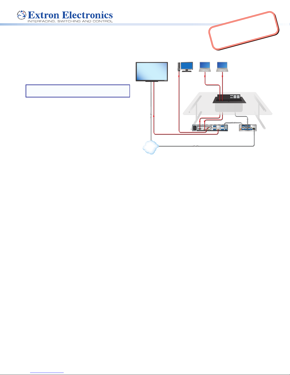
EBP 1200C Cable Cubby Enclosure
Display with Speakers
Laptop Laptop
Computer
with eBUS® Button Panel • Setup Guide
Product Category
m
o
c
.
n
o
IMPORTANT:
Go to www.extron.com for the
pr
r
t
x
e
.
w
w
w
e connecting the
rce.
The Extron EBP1200C is a Cable Cubby® 1200 with an
MODEL 80
integrated eBUS button panel to combine convenient
AV and data connectivity with a fully customizable AV
system control interface for use with Extron IPCPPro
Series Control Processors.
NOTE: These products are only for use with Extron
UL Listed IPCP Pro control processors.
FLAT PANEL
HDMI
VGA
HDMI
Extron
EBP 1200C
Cable Cubby eBUS
Button Panel
ON
OFF
PC
HDMI
LAPTOP
VGA
MUTE
AUX VIDEO
Extron
This guide provides basic instructions for an
experienced installer to install an EBP1200C Cable
Cubby button panel:
• Setup Checklist
• Installing the EBP 1200C Cable Cubby
• Connecting to the eBUS System
For more details on eBUS, see the eBUS Technology
Reference Guide, available on www.extron.com. For
details on conguration, see the software help les.
Setup Checklist
Figure 1. EBP 1200C Application Diagram
Ethernet
Network
TCP/IP
HDMI
100-240V ~ --A MAX
HDMI HDMI3
21CONFIGURABLE
HDMI4
INPUT REMOTE
50-60 Hz
Extron
IN1604 HD
Four Input Scaler
Ethernet
OUT
IN
12
LR
L
R
AUDIOOUTPUT
3214+V
TALLY OUT
HDMI
CONTACT IN
1234G
RS-232
RS-232
TxRx G
Extron
IPCP Pro 250
IP Link Pro
Control Processor
Step 1 — Planning
Download and install the latest version of the software, rmware, and device drivers needed to congure the IPCPPro
and control the connected AV products. See the IPCPPro Series User Guide (available at www.extron.com) for details on
software and drivers.
Obtain network information (IP addresses, passwords, DHCP settings, and the like) and the MAC address for the control
processor.
Obtain model names, drivers, and setup information for AV devices.
Determine which eBUS cabling topologies to use and obtain cables, mounting hardware, and any power supplies or hubs
required by that conguration.
Make sure you are familiar with all the Included parts (see the next page) and have all the necessary tools for installing the
Cable Cubby.
Before cutting a hole in any furniture, select the best location for the EBP 1200C.
• Ensure that the product is oriented so that the lid opens in the desired direction.
• Ensure there is enough space for all the system cables and components, including cable retractors, if they are to be
installed.
Check all relevant regulations (see the next page).
eBUS
COM 1
COM 2
DIGITAL I/O
IPCP PRO 250
G
TxRx RTSCTS
G
TxRx
1 2 3 4 G
POWER
RELAYS
eBUS
IR/S
VOL
12V
1 2 C
VCG
--A MAX
+V+S-SG
S G
PWR OUT = 6W
LAN
Step 2 — Cutting the Table
Decide on the method for cutting a hole in the table (see Cutting the Table on page 3).
Verify that you have the correct cut-out template and dimensions (see Cutting the Table on page 3).
Step 3 — Setting the eBUS ID Address
All eBUS devices connected to the same control processor must have a unique eBUS ID address. This requires access to the
DIP switches on the bottom panel of the EBP 1200C and it is more convenient to set the address before the EBP 1200C is
installed in the table (see Setting the eBUS ID Address on page 10).
1
Page 2
EBP 1200C • Setup Guide (Continued)
34
89
Step 4 — Mounting the EBP 1200C
Connectivity modules allow you to populate the Cable Cubby enclosure with a combination of AAP™ devices, cable
pass-throughs, retractors, or power modules. The EBP 1200C accommodates your choice of any two modules, allowing you
to customize the device to meet your specic needs.
The AAP module and cable pass-through module require some assembly before they can be installed in the EBP 1200C.
Install the modules.
Mount the EBP 1200C.
Install the retractors.
Route the cables.
Step 5 — Changing the Buttons
The EBP 1200C ships with a set of buttons installed and some additional blank buttons ship with the unit. You can order
others from www.extron.com. To replace one or more of the individual buttons, see Changing Buttons on page 9
Step 6 — Connecting to the eBUS System
Connect the EBP 1200C to an eBUS device or control processor.
Congure the system.
Test and troubleshoot.
Planning
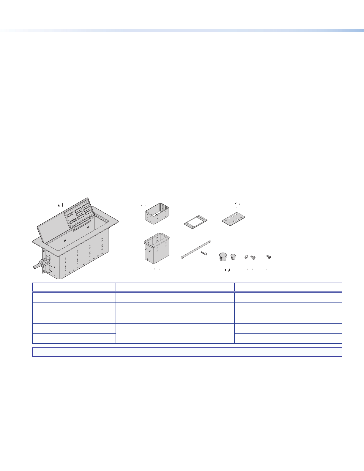
Included parts
11223
21-525-01LF
e
HDMI
VGA
PC
OFF
AUX VIDEO
LAPTOP
ON
MUTE
e
5
566778
4
9
Item Qty Item Qty Item Qty
EBP 1200C
1
Connectivity Bracket
2
AAP Frame Plate
3
Cable Grommet Plate
4
Retractor Bracket
5
1
1*
1 Extron removal tool (not shown) 1
1
1 Blank buttons (not shown) 1
Retractor Pin and Clip
6
Hole Plugs
7
#6 Pan-head Mounting Screws
8
and Star Washers
1
6 (3/8")
2 (1/4")
8 Extron Tweeker (not shown) 1
#4-40 Module Screws
9
NOTE: *A single connectivity bracket is provided. It can be used with either the AAP frame plate or the cable grommet plate.
Figure 2. EBP 1200C Included Parts
Check all relevant regulations
• Ensure the installation complies with local, state, and national building and electrical codes.
• Ensure the installation complies with the Americans with Disabilities Act or other accessibility requirements. When planning
where to install these devices, you may need to consider factors affecting accessibility of the button panel such as height
from the oor, distance from obstructions, and how far a user must reach to press the buttons.
For guidelines, see sections 307 (“Protruding Objects”) and 308 (“Reach Ranges”) of the 2010 ADA Standards for Accessible
Design available at http://www.ada.gov/regs2010/2010ADAStandards/2010ADAStandards.pdf.
8
2
Page 3
Product Category
Installing the EBP 1200C Cable Cubby
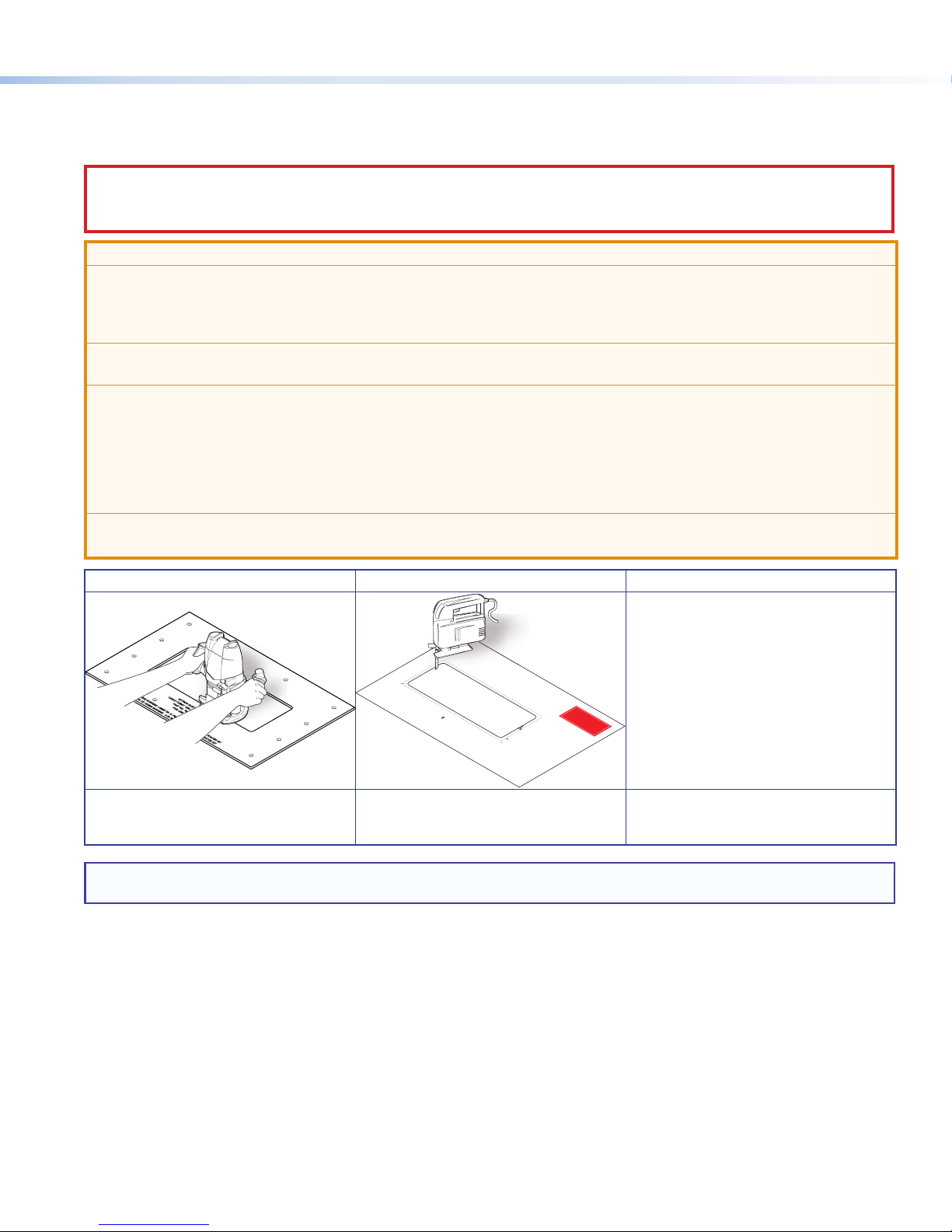
Cutting the Table
CAUTION: Wear safety glasses when operating power equipment. Failure to comply can result in eye injury.
ATTENTION : Portez des lunettes de sécurité lorsque vous utilisez l’équipement électrique. Ne pas respecter cela peut
conduire à une blessure à l’oeil.
ATTENTION:
• The opening in the table for the Cable Cubby should be cut only by licensed and bonded craftspeople. Exercise care
to prevent scarring or damaging the furniture.
• L’ouverture dans la table pour le CableCubby devrait être coupée seulement par des artisans autorisés et qualiés.
Faites attention à ne pas faire de marques sur le meuble et à ne pas l’endommager.
• Follow all national and local building and electrical codes that apply to the installation site.
• Respectez tous les codes électriques et du bâtiment, nationaux et locaux, qui s’appliquent au site de l’installation.
• Use the appropriate metal Extron routing template or refer to the surface cutout dimensions before cutting a hole in
the furniture or other surface. Pay special attention to the direction the unit will face. The connector access side is
underlined (see CNC Wood Router below). Extron is not responsible for miscut mounting holes.
• Utilisez le gabarit de détourage métallique approprié ou reportez-vous aux dimensions de découpe de la surface
indiquées ci-après avant de découper le meuble ou la surface. Faites particulièrement attention à la directions dans
laquelle l’unité sera dirigée. Le côté pour accéder au connecteurs est souligné (voir CNC Wood Router ci-dessous).
Extron ne sera pas responsable des erreurs de coupe.
• Ensure the table surface is at least 0.50 inch (1.27 cm) thick.
• Assurez vous que la surface de la table est au moins 1,27 cm (0,50 pouce) d’épaisseur.
Hand Router and Routing Template Jigsaw and Paper Cut-out Template CNC Wood Router
If using a CNC wood router or other
precise machinery, use the exact
cut-out dimensions:
Cut-O
Cable Cubby 1200
ut Template for the Extron
Cu
0.
tOut
25"
Radius:
(
0.6 cm)
User Access
Visit www.extron.com for the
EBP 1200C routing template part
number and instructions.
The cut-out template and
dimensions are available online at
www.extron.com.
and EBP 1200C
Trim Ring
Lip
Outer Ed
(Do
g
not cut th
e
of Fro
i
s l
i
n
P/N 68-
2
4
72-01
Page Size: 11" x 17"
Print Scale 1:1
Do not Shrink
1. Confirm the produc
2. Remove the s
(gray) from the
3. Me
4
. Mark the
furniture
asure the
wil
5. Double check
urfac
l be
pos
then cut
t to be
c
t
e
e
where the
utout and template
install
mplate
cut-out are
ition on the
installe
ed.
the ope
.
t
Ca
he dimensions
d.
a
ble Cubby
ning.
.
1200
n
t Bezel
e.)
Re
v
. C
and position,
User Access Width
10.00" (25.40 cm)
Depth
4.00" (10.16 cm)
NOTE: The metal router guide must be purchased separately. It is reusable and should not be discarded when the installation
is complete.
3
Page 4
EBP 1200C • Setup Guide (Continued)
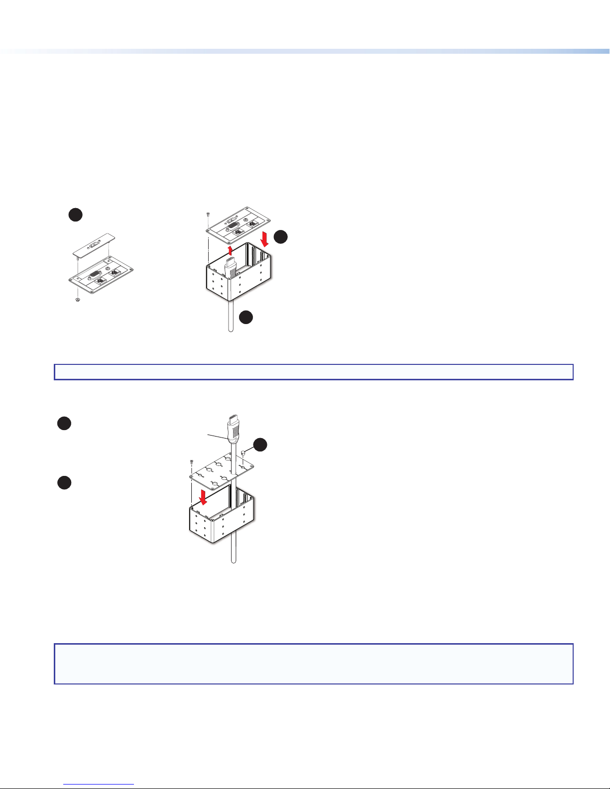
e the AAP plate on the connectivity brackets,
Secure up to three single-space
AAPs in the AAP plate.
Secure the AAP plate on the connectivity brackets,
using four of the provided module screws.
#4-40 Nut with
Captive Washer
Insert cables through the bottom of the connectivity bracket.
Connect cables to the AAPs.
1
3
2
Mounting the EBP 1200C
A variety of modules allow you to populate the Cable Cubby enclosure with a combination of AAPs, cable pass-through,
retractors, or power modules. The EBP 1200C accommodates your choice of any two modules, allowing you to customize the
device to meet your specic needs.
Assemble the Connectivity Modules of your Choice
The EBP 1200C is provided with a single connectivity bracket that can be used with either the AAP frame plate or the cable
grommet plate. Follow the steps below to assemble the connectivity modules of your choice before they can be mounted into the
EBP 1200C.
AAP module
The AAP module accommodates up to three single-space AAPs.
Secure up to three single-space
1
AAPs in the AAP plate.
Secur
3
using four of the provided module screws.
#4-40 Nut with
Captive Washer
Insert cables through the bottom of the connectivity bracket.
2
Connect cables to the AAPs.
Figure 3. Assembling the AAP Module
NOTE: After assembling the AAP module, proceed to Install the Modules below.
Cable pass-through module
The cable pass-through module accommodates up to eight AV cables.
1
Insert cables through the bottom of
the connectivity bracket and into the
holes of the grommet plate.
You may need to bend the
plate gently to slide the cable
past the slot opening.
2
Secure the grommet plate on the
connectivity bracket, using four
of the provided module screws.
Figure 4. Assembling the Cable Pass-through Module
Install the Modules
Determine where the modules are installed in the Cable Cubby. Any combination of two modules can be installed. The modules
can be installed on either side of the enclosure and at various heights.
3
Snap the included
hole plugs into any
unused holes.
NOTES:
• Ensure that there is enough room above the modules for the Cable Cubby lid to close completely.
• Use a screwdriver to secure the modules with the screws.
4
Page 5
Retractor bracket
ews with star washers. Tighten
Se
e and
ews
Use the retractor bracket to mount retractors in the Cable
Cubby enclosure. The retractor bracket accommodates
up to three Retractor Series/2 or Retractor Series/2
XL cable retraction modules. The retractors must be
purchased separately.
If you require retractors, insert the retractor bracket as
shown in gure 5.
Product Category
HDMI
VGA
PC
OFF
AUX VIDEO
LAPTOP
ON
MUTE
e
NOTE: Do not mount the retractors in the retractor
bracket until after the Cable Cubby is mounted
(see Install the Retractors on page 7).
Install retractor ller modules (see www.extron.com) in
any unused retractor mounting spaces.
Optional retractor brackets (see www.extron.com) each
accommodate two cable retraction modules. These
brackets must be purchased separately. They are sold
in pairs and allow the cable retractors to be mounted at
the outer edges of the enclosure with one of the other
modules mounted centrally.
Figure 5. Install the Retractor Bracket
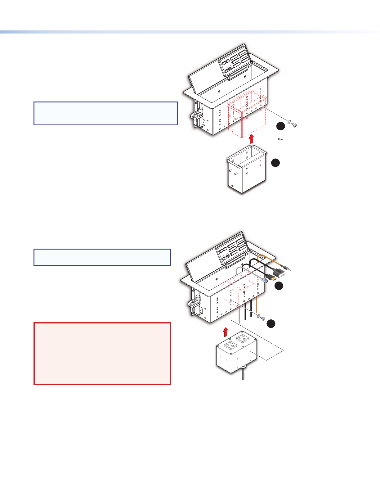
AAP module, cable pass-through module and power module
Insert the modules into the cable cubby as shown in
gure 6.
NOTE: Extron recommends mounting the power
module on the left side of the enclosure.
AC power and AC+USB power modules are available
for US, Europe, and other major world markets. They
must be purchased separately (see www.extron.com).
Most AC power modules provide two unswitched AC
outlets.
The AC+USB power modules provide one or two AC
outlets and two USB power outlets.
WARNING: Risk of Electric Shock. To ensure
proper electrical grounding, use the
provided #6-32 mounting screws with the
star washers.
AVERTISSEMENT : Risque de choc électrique.
An d’assurer une mise à la terre correcte,
utilisez les xations de mise à la terre #6-32 et
les rondelles en étoile fournies.
Figure 6. Install the Connectivity and Power Modules
21-525-01LF
e
2
Secure the bracket using four of
the provided pan-head mounting
scr
the screws using a screwdriver.
1
Insert the bracket as shown.
The bracket may be installed on the
left or right side of the enclosur
at the lowest height.
HDMI
VGA
PC
OFF
AUX VIDEO
LAPTOP
ON
MUTE
e
Insert the modules
1
into the Cable Cubby.
21-525-01LF
e
Secure the modules using
2
four of the provided
pan-head mounting scr
and star washers.
125V~ 12A MAX TOTAL
5
Page 6

EBP 1200C • Setup Guide (Continued)
into the hole to test the t.
nd
face of
h
e
ON
OFF
PC
LAPTOP
MUTE
AUX VIDEO
VGA
HDMI
is rmly seated in the table.
the Cable Cubby.
21-526-0
21-526-0
Locking
plate
Mount the EBP 1200C
TIP: Before mounting the EBP 1200C, you should set the eBUS ID address, since this requires access to the DIP switches,
which are on the bottom of the unit (see Setting the eBUS ID Address on page 10).
Insert the EBP 1200C enclosure into
the table
CAUTION: The anged edges of the top
of the surface enclosure are sharp.
These edges are also soft and may be
easily nicked or bent. Exercise caution
when handling the enclosure to prevent
personal injury or damage to the
enclosure.
ATTENTION : Les extrémités à brides
du haut de la surface du boîtier sont
aiguisées. Ces extrémités sont aussi
lisses et peuvent facilement être coupées
ou pliées. Soyez prudents lorsque vous
manipulez le boîtier an d’éviter de
l’endommager ou de vous blesser.
1
Remove the plastic strips and
astic strips a
lm on the surface of the
Cable Cubby.
2
Ensure that the
side clamps are
seated against the
enclosure.
e
the
HDMI
VGA
PC
OFF
AUX VIDEO
LAPTOP
ON
MUTE
e
3
Lower the Cable Cubby
If necessary, carefully
enlarge the opening.
Figure 7. Insert EBP 1200C Enclosure into the Table
Under the Table, Adjust the Side Clamps on the Enclosure
HDMI
VGA
PC
OFF
AUX VIDEO
LAPTOP
ON
MUTE
e
Lever
01LF
-
525
21
e
21-525-01LF
1
e
NOTE: To lower the side clamp, turn the lever down,
then press and hold the locking plate while sliding
down the clamp.
21-525-01LF
e
e
Rotate the side clamp
outward and ensure
that the lever is down.
Figure 8. Secure the Cable Cubby Enclosure
6
Slide the clamp all the
21 3
way up against the
bottom of the table.
Ensure the Cable Cubby
Raise the lever to secure
Page 7

Product Category
e
ON
OFF
PC
LAPTOP
MUTE
AUX VIDEO
VGA
HDMI
Insert the pin thr
Retractor mounting hole on
the side of the Cable Cubby
and Retractor assembly
. Do not
cables to the holes
Install the Retractors
Retractors can be installed in a vertical, angular, or horizontal orientation. No adjustment of the enclosure screws is needed if the
retractors are mounted vertically. To mount at an angle or horizontally, adjust the enclosure screws as shown below. When the
retractors are mounted horizontally, the retractor mechanism must be secured to the underside of the table (see Cable Retractor
Setup Guide, which is available at www.extron.com).
To secure the retractors in the retractor bracket, follow the instructions in gure 9.
Horizontal Mounting
Cable Release
Assembly
Remove two enclosure screws
(one on each side) from this position.
Then mount the Retractors as shown
at left.
3
2
ough the
.
1
Insert Retractors into
the Retractor bracket.
Figure 9. Installing Retractors
Secure the locking screw
4
on each Retractor
overtighten.
Route and Connect the Cables to Cable Cubby
Secure the clip
on the pin.
See the Cable Retractor Setup Guide, available
at www.extron.com, for additional steps.
Angular Mounting
Remove the two enclosure screws, as shown
above, and then follow this step:
Move the cable release assembly upward until
the angular mounting hole is visible. Reinstall the
enclosure screws in this hole (both sides).
CAUTION: Risk of Electric Shock.
This equipment must be grounded.
ATTENTION : Risque de choc
électrique. Cet équipement doit
être xé au sol.
Figure 10. Route and Connect AV Cables
Connect cables to the AV system
3
and connect the AC power cord.
NOTE: Ensure there is no tension
on the power cable.
Using zip ties, secure
2
on the bottom of the Cable Cubby.
For cable pass-through applications,
1
allow at least 36 inches (0.9 m) of cable
loop for each cable.
7
Page 8

EBP 1200C • Setup Guide (Continued)
BC
Connecting to the eBUS System
The EBP 1200C has two eBUS ports that support power and communication with an IPCPPro control processor. Up to eight
eBUS endpoint devices such as EBP button panels can be connected to the control processor and to each other in various
cabling topologies. These can include daisy chain, star, or hybrid system (a combination of both daisy chain and star) topologies
(see the eBUS Technology Reference Guide, available on www.extron.com, for basic diagrams). Every endpoint device must
have a unique identication address (bus ID) within the system.
Once the bus ID DIP switches are set on the EBPs, use Extron GlobalCongurator® (GC) Plus and Professional software, or
Global Scripter® programming, to congure the control processor. Once congured, the EBPs can control the AV system.
EBP Front Panel Features
NOTE: Use Global Congurator Plus and Professional to congure the EBP buttons and LEDs. Alternatively, use Global
Scripter to program the buttons and LEDs.
Cable Cubby lid — Tilts back to 130°. Friction washers
A
ensure the lid holds any angle set by the user.
A switch in the hinge activates the buttons when the lid
is fully open and deactivates them when the lid is closed
to prevent accidental button presses.
Power buttons — Are labelled ON and OFF and control
B
the power to the display device. The ON button has a
nub that can be felt with the nger tips.
Volume LED meter — Shows the volume level.
C
Volume buttons — Can be used to increment or
D
decrement audio volume. There is also a MUTE button
to the right.
Button panel removal slots — Use the Extron removal
E
tool in these slots to release the top of the panel when
replacing buttons.
Input and function buttons — If these buttons are
F
used to select an input, they can be congured as a
group to act in a mutually exclusive manner. However,
the buttons can also be congured to carry out separate
functions. In that case, they can be removed from the
input group and congured independently.
Transmit LED — Blinks once when any button is
G
pressed.
Button panel hinge — Holds the bottom of the panel in
H
place, allowing the panel to tilt forward when replacing
buttons.
AA
Figure 11. EBP 1200C Front Panel
BB
C
C
D
D
E
E
OFF
ON
F
F
PC
LAPTOP
MUTE
E
E
HDMI
VGA
AUX VIDEO
G
G
H
H
EBP Bottom Panel
DIP switches — Used to provide each unit connected to the same
A
control processor with a unique bus ID (see Setting the eBUS ID
Address on page 10).
eBUS connectors (2 blocks) — These four-pole captive screw
B
blocks connect the EBP 1200C to a controller and to other panels.
Status LEDs — These three LEDs are mutually exclusive (only one
C
LED lights at a time). When the unit is not receiving power, all three
LEDs are off.
• Link — lights green when power and communication with the control processor are both good.
• Com Error — lights amber when there is no communication with the control processor.
• ID Error — lights red when there is a bus ID conict.
Reset button — Resets the rmware to the factory installed version.
D
1. Disconnect the eBUS cable that is providing power.
2. Press and hold down the Reset button while reconnecting power. During the reset process, the front panel buttons are
not lit and the eBUS Link Status LED is lit.
After about 30 seconds, the front panel buttons are lit dimly and the unit rmware is restored to the original
factory-installed version. For information about updating the unit rmware, see the eBUS Technology Reference Guide.
8
AA
ON
CIT
M
PWR LOAD
S
= 2.0W
B
Figure 12. EBP 1200C Bottom Panel
1234 56
BUS ID
L
S
B
B
eBUS Status
+S -S -SG+V+SG
+V
C
LINK COM
ERRORID ERROR
D
D
RESET
Page 9

Product Category
OF
Extron
Extr
on
21-785-01LF
Changing Buttons
You can replace a faceplate or one or more of the individual buttons. Some additional blank buttons ship with the unit. You can
order standard or custom buttons from www.extron.com. To change the buttons:
11
Insert the Extron removal tool into one of the removal
3
3
2
2
HDMI
VGA
PC
OFF
ON
LAPTOP
MUTE
e
AUX VIDEO
11
slots in the top edge of the button panel.
Carefully release the corner of the panel.
Repeat step 1 to release the opposite corner of
22
the panel.
Tilt the lid forward to prevent the buttons from
33
falling out.
Pull the top of the button panel forward. The
44
panel is attached to the lid with a hinge that
allows access to the buttons without the panel
4
4
7
5
5
7
66
Back of
Button Panel
££
¢
¢
9
9
£
£
HDMI
VGA
PC
OFF
ON
LAPTOP
MUTE
AUX VIDEO
e
¤¤
becoming completely detached.
You can now return the lid to the fully open position.
From the front of the panel, press the button
55
until it is free of the panel.
From the back of the button panel, insert the
66
replacement button into the appropriate slot.
Ensure the text is in the correct orientation.
Align the two pegs on the button with the holes
on the button panel.
Press the button into the faceplate until the
77
pegs on the button are seated securely in the holes.
Repeat steps 5-7 for any other buttons that
88
need to be replaced.
Tilt the lid forward to prevent the buttons from
99
falling out.
Tilt the lid and the button panel backwards.
¢¢
Press the top corners so that they snap back
££
into place, securely attaching the button panel
to the lid.
If the corners do not snap back easily, you
may need to adjust how the button panel is
seated in the hinge attaching it to the lid ( ).
¤¤
Figure 13. Replacing Buttons
9
Page 10

EBP 1200C • Setup Guide (Continued)
D
0W
T
US
D
OR
M
BUS ID
S
BUS ID
S
BUS ID
S
BUS ID
S
BUS ID
S
BUS ID
S
BUS ID
S
B
BUS ID
Setting the eBUS ID Address
Up to eight units can be connected to one control processor.
Each unit connected to the same control processor must
have a unique six-bit, binary eBUS ID (address), which is set
with the DIP switch assembly on the bottom panel of the
EBP 1200C (gure 14).
eBUS Status
eB
CIT
L
L
S
B
I
G
PWR LOAD
PWR LOA
= 2.
= 2.0W
ON
N
ON
M
M
S
S
B
B
B
1234 56
1234 56
BUS ID
BUS ID
Figure 14. DIP Switches on EBP 1200C Bottom Panel
If other modules have the same bus ID, address conicts
may cause one or more of the panels to not be recognized
by the IPCPPro control processor.
Set the bus identication DIP switches for each EBP button
panel in the system using the diagrams in this section as a
guide.
NOTES:
• By factory default, the EBP 1200C is set to
address 26 (binary: 011010), as shown in the
diagram below.
• Any address can be used except address
0 (binary: 000000). This is reserved as the
address of the controller and may not be used.
• Switch 1 (on the left) is the highest value (32,
the most signicant bit) and is labelled MSB.
• Switch 6 (on the right) is the lowest value (1,
the least signicant bit) and is labelled LSB.
• Up = on = 1, Down = off = 0
ON
S
B
1 2
CIT
L
S
B
56
4
3
tatus
LINK COM
LINK
ERR
ERRORID ERROR
Slide
I
ERROR
RESET
RESE
Example eBUS IDs
Address eBUS ID DIP Switch
0 000000*
*Reserved for
controller address
ON
M
S
B
1 2
CIT
56
4
3
BUS ID
1 000001
ON
M
S
B
1 2
CIT
56
4
3
BUS ID
2 000010
3 000011
4 000100
5 000101
6 000110
7 000111
ON
1 2
ON
1 2
ON
1 2
ON
1 2
ON
1 2
ON
1 2
CIT
56
4
3
CIT
56
4
3
CIT
56
4
3
CIT
56
4
3
CIT
56
4
3
CIT
56
4
3
L
S
B
L
S
B
L
S
B
L
S
B
L
S
B
L
S
B
L
S
B
L
S
B
10
8 001000
ON
1 2
CIT
L
S
B
56
4
3
Page 11

Product Category
+
Drain Wires
G
S
+S
+V
Cable All Devices
Attach cables using the diagrams in this section as a guide. Connect a 4-pole captive screw connector to each end of the cable,
wiring both ends as shown in gure 15. In most cases the EBPs are powered by the IPCPPro control processor that provides the
eBUS signal. Power is carried on the V+ pin of each eBUS connection.
The four connectors are:
• +V — carries 12 VDC power from the controller, active hub, or power supply
• +S — carries the positive data signal
• -S — carries the negative data signal
• G — ground
Extron STP20-2/1000 or STP20-2P/1000 cable is recommended for eBUS connections.
12 VDC
+ Signal
-
Signal
Ground
Figure 15. Basic eBUS Connector Wiring and Cable Color Code
For long cable runs, category cable can provide a convenient option for eBUS signals. For these applications, compatible 4-pole
captive screw to RJ-45 adapters are available at www.extron.com.
Extron recommends using shielded CAT6 cable.
Red
Green
White
Black
-
NOTES:
• The two eBUS blocks are interchangeable: either block can be used to connect the unit to a controller or EBDB and
either can be used to daisy-chain the unit to another EBP.
• Connect up to eight eBUS endpoint devices for each IPCP Pro control processor.
• Wire the connectors in the same way at both ends.
• See the eBUS Technical Reference Guide (available at www.extron.com) for information about the maximum cable
distance and power requirements for your eBUS system.
• Do NOT power an EBP from more than one power source.
ATTENTION:
• Always use a power supply supplied or specied by Extron. Use of an unauthorized power supply voids all regulatory
compliance certication and may cause damage to the supply and the unit.
• Utilisez toujours une source d’alimentation fournie par Extron. L’utilisation d’une source d’alimentation non autorisée
annule toute conformité réglementaire et peut endommager la source d’alimentation ainsi que l’unité.
• If not provided with a power supply, this product is intended to be supplied by a UL Listed power source marked
“Class2” or “LPS” and rated output 12VDC, minimum 1.0A.
• Si ce produit ne dispose pas de sa propre source d’alimentation électrique, il doit être alimenté par une source
d’alimentation certiée UL de classe 2 ou LPS et paramétré à 12VDC et 1,0A minimum.
• Unless otherwise stated, the AC/DC adapters are not suitable for use in air handling spaces or in wall cavities.
• Sauf mention contraire, les adaptateurs AC/DC ne sont pas appropriés pour une utilisation dans les espaces
d’aération ou dans les cavités murales.
• The installation must always be in accordance with the applicable provisions of National Electrical Code ANSI/
NFPA70, article725 and the Canadian Electrical Code part1, section16. The power supply shall not be permanently
xed to building structure or similar structure.
• Cette installation doit toujours être en accord avec les mesures qui s’applique au National Electrical Code ANSI/
NFPA70, article725, et au Canadian Electrical Code, partie1, section16. La source d’alimentation ne devra pas être
xée de façon permanente à une structure de bâtiment ou à une structure similaire.
11
Page 12

EBP 1200C • Setup Guide (Continued)
S
X
#
S
6-
XX-XX-XX
#
Extron P/N 28-071-57LF)
EBPs that are relatively far from the control processor (see the eBUS Technology Reference Guide on www.extron.com for
details) can be connected to an optional Extron PS1220EB eBUS power inserter, or an Extron 12VDC desktop power supply as
shown in the following diagrams.
.0A MAX
COM 1
WER
TST
VOL
COM 2
RELAYS
DIGITAL I/O
eBUS
-S+V +S G
PWR OUT = 6W
IPCP PRO 250
AC: 00-05-A6-XX-XX-X
N: ####### E#####
IR/S
100-240V 50-60Hz
0.6A MAX
-S+V +S G-S+V +S G-S+V +S G
eBUS 24 WATTS MAX
-S+V +S G-S+V +S G -S+V +S G
eBUS Connections
• Connect up to ve (5) eBUS
endpoint devices to the PS 1220EB.
• Wire the connectors the same at both
ends.
• All ports are identical and
interchangeable.
IPCP Pro
X
Power Input
(100-240 VAC,
50-60 Hz)
ATTENT ION: Do NOT connect the
power pin to a ny device that is already
powere d by the IPC P Pro control
processor or by an additional power
suppl y.
+ Signal
-
Signal
Ground
Tie drain wires
to ground.
Figure 16. Powering an eBUS System with an PS 1220EB Power Inserter
M
PWR LOAD
S
= 2.0W
B
EBP 1200C
ATTENT ION: Do NOT connect the
power pin from th e IPCP Pro
control processor to a devi ce that
COM 1
x
WER
.0A MAX
TST
VOL
COM 2
x
x
RELAYS
DIGITAL I/O
eBUS
-S+V +S G
PWR OUT = 6W
IPCP PRO 250
IR/S
AC: 00-05-A
N: ####### E#####
IPCP Pro
EBP wall panel
is powe red by a sepa rate power
suppl y.
3/16" (5 mm) Max.
X
Tie drain wires to ground.
External Power Supply
(12 VDC, 1 A max.,
X
ON
1234 56
BUS ID
Ground
-
Signal
+ Signal
Ground
-
Signal
+ Signal
+12 VDC
PS 1220EB
+12 VDC
+ Signal
-
Signal
Ground
M
PWR LOAD
S
= 2.0W
B
EBP 1200C
eBUS Status
CIT
L
S
B
+S -S -SG+V+SG
+V
X
+12 VDC input
– Return
Ground
all Devices
3/16" (5 mm) Max.
ON
1234 56
BUS ID
eBUS Status
CIT
L
S
B
+S -S -SG+V+SG
+V
LINK COM
ERRORID ERROR
RESET
Smooth
Power Supply
Output Cord
RidgedSmooth
SECTION A–A
NOTE:
Check the polarity of the power
supply before connecting it to the EBP.
LINK COM
ERRORID ERROR
RESET
Ridges
G
AA
G
Figure 17. Powering an eBUS System with an Extron 12VDC, 1 A Power Supply
12
Page 13

Product Category
Configure the System
NOTE: EBPs are shipped with pre-labelled buttons in place but these buttons do not have any functions associated with them
until they are congured with Global Congurator or programmed with Global Scripter. See the Global Configurator Help
File or Global Scripter Help File as needed for step-by-step instructions and detailed information.
1. Create a new Global Congurator Plus or Professional project and congure the controller and any eBUS devices. The
conguration tells the control processor how its ports function; how to control other products; what to monitor; when to do
things; and whom to notify, how, and under what circumstances.
a. Congure ports on the control processor.
• Select device drivers and link them to each assigned port.
• Congure settings (serial protocol, relay behavior, digital input, volume control settings) as needed.
b. Set up monitors, schedules, macros, and local variables.
c. Set up the eBUS button panel buttons: assign appropriate commands and actions, macros, timers, local variables
monitors, or feedback to the buttons.
2. Save the project.
3. Build and upload the system conguration to the control processor.
NOTE: Once the Global Congurator project has been set up, you can use Global Scripter to program buttons and LEDs.
Test and Troubleshoot
1. Verify that the DIP switches on the EBPs are set to the desired address on each unit and that there are no DIP switch address
conicts in the system. If there is a bus ID conict, the ID Error status LED lights red (see EBP Bottom Panel on page 8).
2. Verify that cables to and from the EBPs are wired the same at each end (pin 1 to pin 1, pin 2 to pin 2, and so forth). If there is
no communication with the control processor, the Com Error status LED lights amber. If power and communication with the
control processor are both good, the Link status LED lights green (see EBP Bottom Panel on page 8).
3. Test the system.
• Press buttons on the EBPs and ensure the buttons light as desired and that the appropriate control commands or
functions are triggered.
• Ensure that the audio output responds correctly to the volume knob or button. Also ensure that the volume LEDs light
correctly as you increase or decrease the audio gain.
4. Make adjustments to wiring, bus ID address, or system conguration as needed. Remember that the rear panel ports and DIP
switches may not be accessible after the EBP is mounted. If needed, upload a revised conguration to the control processor.
If you have questions during installation and setup, you can le an online technical support request or call the ExtronS3 Control
Systems Support Hotline (1.800.633.9877).
13
Page 14

EBP 1200C • Setup Guide (Continued)
Extron Headquarters
+1.800.633.9876 (Inside USA/Canada Only)
Extron USA - West Extron USA - East
+1.714.491.1500 +1.919.850.1000
+1.714.491.1517 FAX +1.919.850.1001 FAX
© 2017 Extron Electronics All rights reserved. All trademarks mentioned are the property of their respective owners. www.extron.com
14
Extron Europe
+800.3987.6673
(Inside Europe Only)
+31.33.453.4040
+31.33.453.4050 FAX
Extron Asia
+65.6383.4400
+65.6383.4664 FAX
Extron Japan
+81.3.3511.7655
+81.3.3511.7656 FAX
Extron China
+86.21.3760.1568
+86.21.3760.1566 FAX
Extron Middle East
+971.4.299.1800
+971.4.299.1880 FAX
Extron Australia
+61.8.8113.6800
+61.8.8351.2511 FAX
Extron India
1800.3070.3777
(Inside India Only)
+91.80.3055.3777
+91.80.3055.3737 FAX
68-1449-52 Rev. A
05 17
 Loading...