

Page 1
Product Category
complete user guide and installation
instructions befor
oduct to the power sou
EB
BC
BE
IMPORTANT:
EBP 108 RAAP Button Panel • Setup Guide
The Extron eBUS® 108 RAAP Button Panel (EBP) is a fully-customizable AV system control interface with eight buttons and a
rotary encoder and eight-segment LED level indicator. It is designed for use with Extron eBUS-enabled Pro control systems. The
1U, 19 inches wide metal frame can be mounted in any standard equipment rack and the mounting plate has openings for up to
four single-space or two double-space AAP™ Architectural Adapter Plates.
NOTE: These products are for use only with Extron UL Listed IPCP Pro control processors.
The EBP 108 RAAP has four eBUS ports that support power and communications between the IPCPPro control processor
and eBUS devices, and also accommodate system expansion. Up to eight eBUS endpoint devices such as EBP button panels
and ECM control modules can be connected to the control processor and to each other in various cabling topologies. Cabling
topology refers to the physical layout of cabling interconnections between devices in a network such as an eBUS system. eBUS
systems can include daisy-chain, star, or a combination of both topologies (see the eBUS Technology Reference Guide, available
at www.extron.com, for basic diagrams). Every endpoint device must have a unique identication address (bus ID) within the
system.
Setup involves setting bus ID DIP switches on the EBPs, then using Extron GlobalCongurator® Plus and Professional (GCP)
conguration software, the Toolbelt utility software, or Global Scripter® programming software to congure the control processor.
Once congured, the panels can be used for AV system control.
This guide provides basic instructions for an experienced installer to install any of these panels. For more details on the EBPs, see
the eBUS Technology Reference Guide. For details on conguration, see the software help les.
www.extron.com
Go to www.extron.com for the
pr
e connecting the
rce.
Features
Rear Panel Features
AA AAB
P 108 RAAP Rear Panel
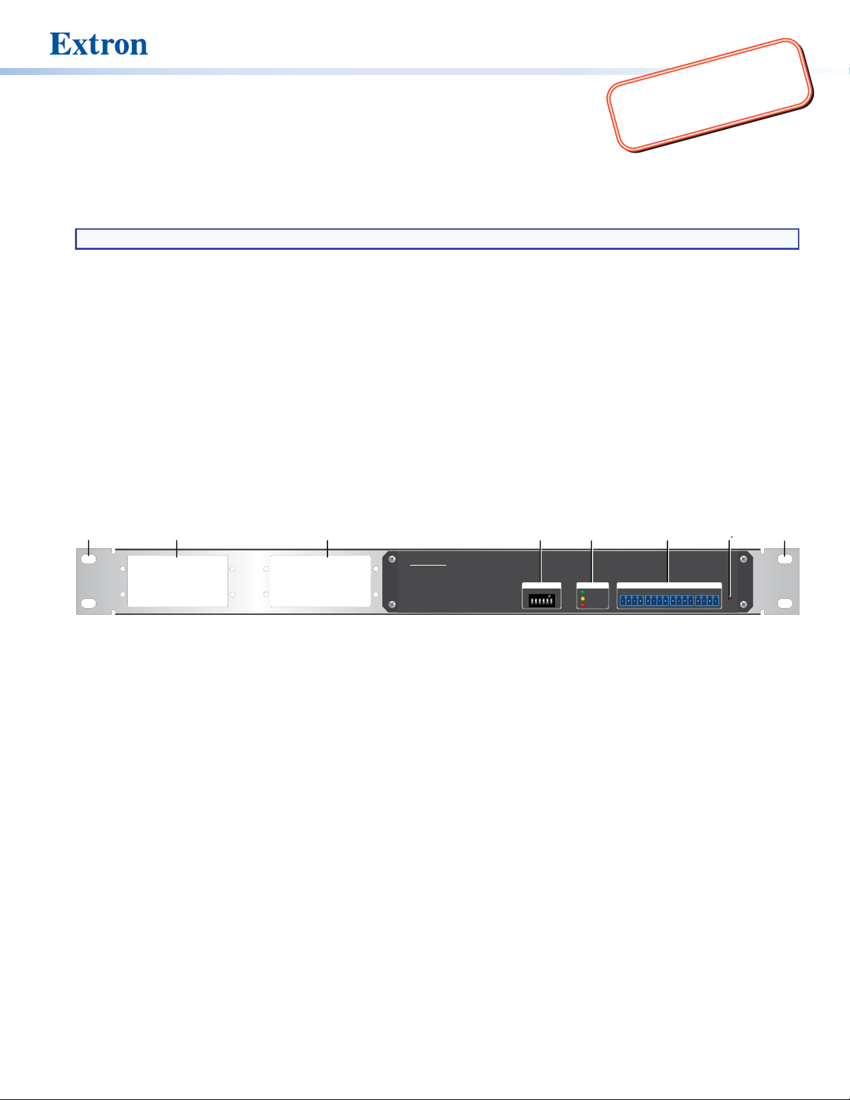
Figure 1. EBP Rear Panel Features
Rack Mounting Holes — Used to mount the device to standard 19-inch equipment racks (see Step 8: Mount the EBPs on
A
page 10).
AAP Mounting Slots — Used to mount up to four single-space or two double-space AAPs.
B
BUS ID DIP Switches — Up to eight devices can be connected to one control processor. Each device connected to the
C
same control processor must have a unique BUS ID, which is set using DIP switches (see Step 4: Set BUS ID Addresses on
page 4).
Status LEDs — The EBP 108 RAAP has yellow, red, and green LEDs that provide diagnostic information about the
D
connection, communication, and power status of the panels. For more information about how the LEDs are used for
troubleshooting, see Step 7: Test and Troubleshoot on page 9.
eBUS Distribution Hub (4 ports) — The four-pole captive screw connectors use the Extron eBUS protocol to connect the
E
panel to a controller and to other panels (see Step 5: Cable All Devices on page 7).
Reset Button — If required, press this recessed button to reset the rmware to the factory installed version.
F
EBP 108 RAAP
M
S
B
CDDB
BUS ID
1ON23456
EFF
STATUS
+V +S -S G +V +S -S G +V +S -S G +V +S -S G
LINK
L
COM ERROR
S
B
ID ERROR
POWER LOAD = 0.5 W
eBUS DISTRIBUTION HUB
RESET
1
Page 2
EBP 108 RAAP Button Panel • Setup Guide (Continued)
To reset the firmware
1. Disconnect the eBUS cable that is providing power.
2. Press and hold down the Reset button and, while holding down the Reset button, reconnect eBUS cable.
3. Release the Reset button 1 second after reconnecting power. During the reset process, the front panel buttons are not lit.
When the eBUS Connection Status LED lights, the reset process is complete.
NOTES:
• If the reset is carried out while the EBP is receiving power from a 12 VDC power supply, the rmware is reset to the
factory default.
• If the reset is carried out while the EBP is receiving power from a control processor, the rmware is reset to the factory
default but the control processor may then push a more recent version of the rmware to the EBP.
Front Panel Features
AA
PC
ON OFF
LAPTOP
DDDD
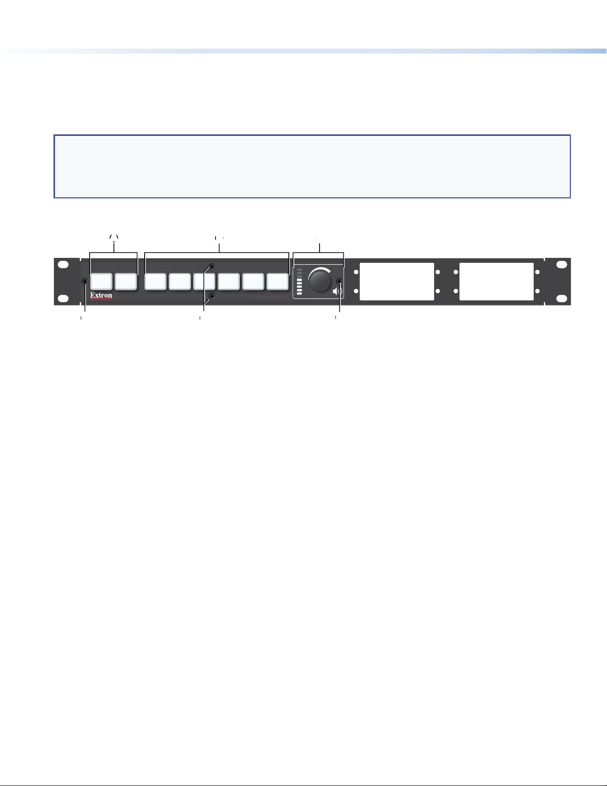
Figure 2. EBP 108 RAAP Front Panel
The buttons and encoders must be congured or programmed to carry out their functions.
Power Buttons — These two buttons control the power to a display
A
Function Buttons — These six buttons can be set up to carry out a variety of functions, either by conguration with Global
B
Congurator Plus and Professional, or programming with Global Scripter, (see the software help le for more information).
Volume Control LEDs and Rotary Encoder — Use the encoder to adjust the volume level. The LEDs provide a visual
C
representation of the volume level.
Front Panel Screws — These four Phillips-head screws hold the faceplate to the unit.
D
B
B CC
VGA HDMI
DOC
CAM
EBP 108 RAAP
MUTE
D
D
Planning the System and Installation
When planning to install an eBUS system you must consider how many EBP button panels to use, maximum cable distance,
cabling topology, and mounting. See the eBUS Technology Reference Guide for more information about eBUS topologies.
Installation
Step 1: Get Ready
Use the following checklist to prepare for the installation.
Download and install the latest version of the software, rmware, and device drivers needed to congure the IPCPPro control
processor and control the connected AV products. See the IPCPPro Series User Guide (available at www.extron.com) for
details on software and drivers.
Obtain network information (IP addresses, passwords, DHCP settings, and so on) and the MAC address for the control
processor.
Obtain model names, drivers, and setup information for AV devices.
Determine which eBUS cabling topologies to use and obtain cables, mounting hardware, and any power supplies or hubs
required by that conguration (see the eBUS Technology Reference Guide for more information about eBUS topologies).
2
Page 3
Product Category
Separate the
two-piece button
her
fuser
Base
1
Step 2: Prepare the Installation Site
ATTENTION:
• Installation and service must be performed by authorized personnel only.
• L’installation et l’entretien doivent être effectués par le personnel autorisé uniquement.
• If the EBP will be installed into ne furniture, it is best to hire a licenced, bonded craftsperson to cut the access hole
and perform the physical installation so the surface will not be damaged.
• S’il est prévu d’installer le EBP dans du beau mobilier, il est préférable de faire appel à un artisan autorisé et qualié
pour couper le trou d’accès et réaliser l’installation de telle façon que la surface ne soit pas endommagée.
• Follow all national and local building and electrical codes that apply to the installation site.
• Respectez tous les codes électriques et du bâtiment, nationaux et locaux, qui s’appliquent au site de l’installation.
Americans with Disabilities Act (ADA) compliance
When planning where to install these devices, you may need to consider factors affecting accessibility of the button panel such
as height from the oor, distance from obstructions, and how far a user must reach to press the buttons. For guidelines, see
sections 307 (“Protruding Objects”) and 308 (“Reach Ranges”) of the 2010 ADA Standards for Accessible Design available at
http://www.ada.gov/regs2010/2010ADAStandards/2010ADAStandards.pdf.
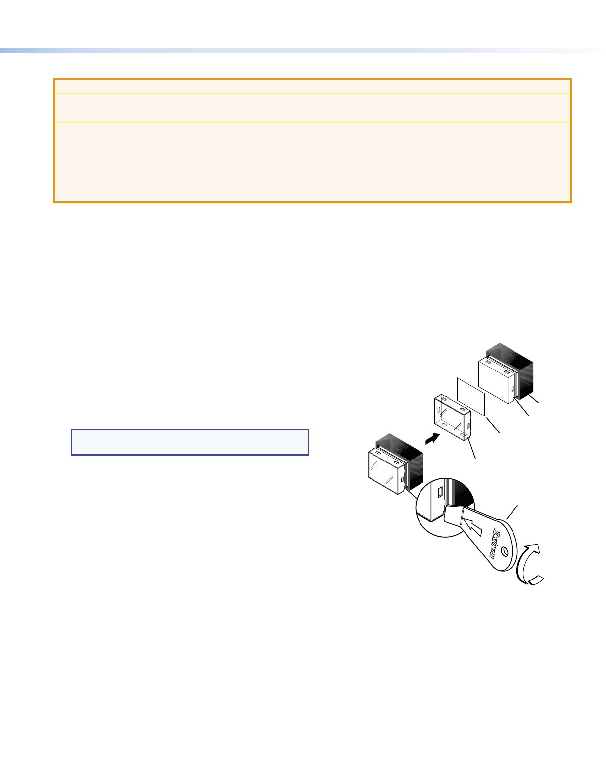
Step 3: Change Button Labels or Knob
You can replace button labels or the volume control knob. Some button labels ship with the unit. You can create and print your
own customized labels using Extron Button Label Generator software.
Changing the button labels
1. Remove the four Phillips-head screws holding the
faceplate to the unit (see figure 2, D, on the previous
page) and remove the faceplate.
2. Gently separate the button lens cap from its white diffuser,
insert the end of the provided Extron removal tool into the
corner notch, and gently twist the tool (see gure 3, 1).
3. Remove the label insert from the button cap.
TIP: If the insert does not come out easily, use a piece
of sticky tape to pull it out of the button cap.
4. Select one of the button labels from the printed label
sheets included with the unit. Remove the label from its
backing and remove the clear, protective lm from the
other side of the label.
5. Insert the button label into the button cap (
6. Align the cap with the white diffuser and the panel
opening, and press the clear cap into place on the button.
7. Attach the faceplate to the EBP by aligning the openings
of the faceplate with the buttons, the knob, and the LEDs
and place the faceplate against the unit.
8. Secure the faceplate to the unit using the four
Phillips-head screws removed in step 1.
2
).
TEXT
Dif
2
Insert
button label.
Button
Lens Cap
Removal
Tool
e at the corner.
Figure 3. Replacing Buttons
3
Page 4

EBP 108 RAAP Button Panel • Setup Guide (Continued)
M
BUS ID
EBP 108 RAAP Top View
Replacing the volume control knob
1. To remove a knob, rmly grasp the knob and pull it away
from the EBP. There is no need to remove the faceplate.
2. To replace the knob, align the ridge inside the new knob
(gure 4, 1) with the channel on the knob control (2)
and allow the magnet in the knob to snap into place.
1
2
Figure 4. Replacing the Volume Control Knob
Step 4: Set BUS ID Addresses
Up to eight devices can be connected to one control processor. In order for the control processor to be successfully congured,
each device connected to the same control processor must have a unique six-bit, BUS ID, which is set with the DIP switch
assembly on the rear panel of the EBP (see figure 1, C, on page 1). If two or more modules have the same bus ID, address
conicts may cause one or more of the panels to not be recognized by the IPCPPro control processor. If there is an address
conict, the red status LED (figure 1, D) lights steadily (see also Step 7: Test and Troubleshoot, step 2 on page 9).
Various combinations of the six DIP switches set to On or Off provide 64 addresses: 0 is a reserved eBUS ID and the congurable
eBUS ID range is 1 through 63 (see the table on the two following pages). The section below shows an example of binary to
decimal conversion.
eBUS ID Setup
Dip Switch
ON
S
B
Figure 5. eBUS ID Setup
1 2
4
3
56
L
S
B
Slide
Position
Decimal
1
Off
Off
5
4
2
=32
2
Add the decimal numbers for each of the DIP switches that are set to On to obtain the address of the device. In gure 5, only DIP
switch #5 is on and the rest are off, which means the address for the device in gure 5 is 0+0+0+0+2+0=2.
NOTES:
• Any address can be used except address 0 (binary: 000000), which is reserved as the address of the controller.
• Switch 1 (on the left) is the highest value (32, the most signicant bit) and is labelled MSB.
• Switch 6 (on the right) is the lowest value (1, the least signicant bit) and is labelled LSB.
• Up = On = 1, Down = Off = 0
The factory default address for the EBP 108 RAAP is 25 (BUS ID = 011001). The ID can be changed to any valid value.
The table on the following two pages shows the DIP switch settings for all 64 possible addresses.
2
=16
3
4
Off
3
2
2
=8
Off
2
=4
2
On
1
5
=2
6
Off
0
2
=1
4
Page 5

Product Category
Setting eBUS ID Numbers
In the table below, a DIP switch setting shown as 0 is equivalent to Off. A DIP switch setting shown as 1 is equivalent to On.
NOTE: The ID number 0 (switch setting 000000) is reserved for the control processor and cannot be used by an eBUS device.
DIP Switch Setting
1 2 3 4 5 6 1 2 3 4 5 6
ON
M
S
B
1 2
ON
M
S
B
1 2
ON
M
S
B
1 2
ON
M
S
B
1 2
ON
M
S
B
1 2
ON
M
S
B
1 2
ON
M
S
B
1 2
ON
M
S
B
1 2
ON
M
S
B
1 2
ON
M
S
B
1 2
ON
M
S
B
1 2
ON
M
S
B
1 2
ON
M
S
B
1 2
ON
M
S
B
1 2
ON
M
S
B
1 2
56
4
3
56
4
3
56
4
3
56
4
3
56
4
3
56
4
3
56
4
3
56
4
3
56
4
3
56
4
3
56
4
3
56
4
3
56
4
3
56
4
3
56
4
3
0 0 0 0 0 0
L
S
B
0 0 0 0 0 1
L
S
B
0 0 0 0 1 0
L
S
B
0 0 0 0 1 1
L
S
B
0 0 0 1 0 0
L
S
B
0 0 0 1 0 1
L
S
B
0 0 0 1 1 0
L
S
B
0 0 0 1 1 1
L
S
B
0 0 1 0 0 0
L
S
B
0 0 1 0 0 1
L
S
B
0 0 1 0 1 0
L
S
B
0 0 1 0 1 1
L
S
B
0 0 1 1 0 0
L
S
B
0 0 1 1 0 1
L
S
B
0 0 1 1 1 0
L
S
B
Decimal
Value
0
1
2
3
4
5
6
7
8
9
10
11
12
13
14
DIP Switch Setting
ON
M
S
B
1 2
ON
M
S
B
1 2
ON
M
S
B
1 2
ON
M
S
B
1 2
ON
M
S
B
1 2
ON
M
S
B
1 2
ON
M
S
B
1 2
ON
M
S
B
1 2
ON
M
S
B
1 2
ON
M
S
B
1 2
ON
M
S
B
1 2
ON
M
S
B
1 2
ON
M
S
B
1 2
ON
M
S
B
1 2
ON
M
S
B
1 2
56
4
3
56
4
3
56
4
3
56
4
3
56
4
3
56
4
3
56
4
3
56
4
3
56
4
3
56
4
3
56
4
3
56
4
3
56
4
3
56
4
3
56
4
3
0 0 1 1 1 1
L
S
B
0 1 0 0 0 0
L
S
B
0 1 0 0 0 1
L
S
B
0 1 0 0 1 0
L
S
B
0 1 0 0 1 1
L
S
B
0 1 0 1 0 0
L
S
B
0 1 0 1 0 1
L
S
B
0 1 0 1 1 0
L
S
B
0 1 0 1 1 1
L
S
B
0 1 1 0 0 0
L
S
B
0 1 1 0 0 1
L
S
B
0 1 1 0 1 0
L
S
B
0 1 1 0 1 1
L
S
B
0 1 1 1 0 0
L
S
B
0 1 1 1 0 1
L
S
B
Decimal
Value
15
16
17
18
19
20
21
22
23
24
25
26
27
28
29
5
Page 6

EBP 108 RAAP Button Panel • Setup Guide (Continued)
DIP Switch Setting
1 2 3 4 5 6 1 2 3 4 5 6
ON
M
S
B
1 2
ON
M
S
B
1 2
ON
M
S
B
1 2
ON
M
S
B
1 2
ON
M
S
B
1 2
ON
M
S
B
1 2
ON
M
S
B
1 2
ON
M
S
B
1 2
ON
M
S
B
1 2
ON
M
S
B
1 2
ON
M
S
B
1 2
ON
M
S
B
1 2
ON
M
S
B
1 2
ON
M
S
B
1 2
ON
M
S
B
1 2
ON
M
S
B
1 2
ON
M
S
B
1 2
56
4
3
56
4
3
56
4
3
56
4
3
56
4
3
56
4
3
56
4
3
56
4
3
56
4
3
56
4
3
56
4
3
56
4
3
56
4
3
56
4
3
56
4
3
56
4
3
56
4
3
0 1 1 1 1 0
L
S
B
0 1 1 1 1 1
L
S
B
1 0 0 0 0 0
L
S
B
1 0 0 0 0 1
L
S
B
1 0 0 0 1 0
L
S
B
1 0 0 0 1 1
L
S
B
1 0 0 1 0 0
L
S
B
1 0 0 1 0 1
L
S
B
1 0 0 1 1 0
L
S
B
1 0 0 1 1 1
L
S
B
1 0 1 0 0 0
L
S
B
1 0 1 0 0 1
L
S
B
1 0 1 0 1 0
L
S
B
1 0 1 0 1 1
L
S
B
1 0 1 1 0 0
L
S
B
1 0 1 1 0 1
L
S
B
1 0 1 1 1 0
L
S
B
Decimal
Value
30
31
32
33
34
35
36
37
38
39
40
41
42
43
44
45
46
DIP Switch Setting
ON
M
S
B
1 2
ON
M
S
B
1 2
ON
M
S
B
1 2
ON
M
S
B
1 2
ON
M
S
B
1 2
ON
M
S
B
1 2
ON
M
S
B
1 2
ON
M
S
B
1 2
ON
M
S
B
1 2
ON
M
S
B
1 2
ON
M
S
B
1 2
ON
M
S
B
1 2
ON
M
S
B
1 2
ON
M
S
B
1 2
ON
M
S
B
1 2
ON
M
S
B
1 2
ON
M
S
B
1 2
56
4
3
56
4
3
56
4
3
56
4
3
56
4
3
56
4
3
56
4
3
56
4
3
56
4
3
56
4
3
56
4
3
56
4
3
56
4
3
56
4
3
56
4
3
56
4
3
56
4
3
1 0 1 1 1 1
L
S
B
1 1 0 0 0 0
L
S
B
1 1 0 0 0 1
L
S
B
1 1 0 0 1 0
L
S
B
1 1 0 0 1 1
L
S
B
1 1 0 1 0 0
L
S
B
1 1 0 1 0 1
L
S
B
1 1 0 1 1 0
L
S
B
1 1 0 1 1 1
L
S
B
1 1 1 0 0 0
L
S
B
1 1 1 0 0 1
L
S
B
1 1 1 0 1 0
L
S
B
1 1 1 0 1 1
L
S
B
1 1 1 1 0 0
L
S
B
1 1 1 1 0 1
L
S
B
1 1 1 1 1 0
L
S
B
1 1 1 1 1 1
L
S
B
Decimal
Value
47
48
49
50
51
52
53
54
55
56
57
58
59
60
61
62
63
6
Page 7

Product Category
+
Drain Wires (2)
G
S
+S
+V
Step 5: Cable All Devices
Attach cables using the diagrams in this section as a guide. Connect a 4-pole captive screw connector to each end of the cable,
wiring both ends as shown in gure 6. In most cases the EBPs are powered by the IPCPPro control processor that provides the
eBUS signal. Power is carried on the V+ pin of each eBUS connection.
The four connectors are:
• +V — carries 12 VDC power from the controller, active hub, or power supply
• +S — carries the positive data signal
• -S — carries the negative data signal
• G — ground
Extron STP20-2/1000 or STP20-2P/1000 cable is recommended for eBUS connections.
12 VDC
+ Signal
-
Signal
Ground
Figure 6. Basic eBUS Connector Wiring and Cable Color Code
NOTES:
• The four eBUS ports are interchangeable: any port can be used to connect the device to a controller or EBDB
distribution hub and any port can be used to daisy-chain the device to another EBP.
• Connect up to eight eBUS devices for each IPCP Pro control processor.
• Wire the connectors in the same way at both ends.
• Do not exceed a total of 1000 feet (305 meters) of cable for connections between the IPCP Pro and all the EBP panels.
• Do NOT power an EBP from more than one power source. Power is provided by the IPCP Pro. If additional power is
required, use a PS 1220EB power supply and distribution hub, or an Extron 12 VDC power supply. If more than one
power source is used in a system, disconnect the +V pin appropriately to ensure that the devices powered by the rst
source are isolated from the devices powered by the second source by (see figure 7 on the following page).
Red
Green
White
Black
-
ATTENTION:
• Always use a power supply supplied or specied by Extron. Use of an unauthorized power supply voids all regulatory
compliance certication and may cause damage to the supply and the unit.
• Utilisez toujours une source d’alimentation fournie par Extron. L’utilisation d’une source d’alimentation non autorisée
annule toute conformité réglementaire et peut endommager la source d’alimentation ainsi que l’unité.
• If not provided with a power supply, this product is intended to be supplied by a UL Listed power source marked
“Class2” or “LPS” and rated output 12VDC, minimum 1.5A.
• Si ce produit ne dispose pas de sa propre source d’alimentation électrique, il doit être alimenté par une source
d’alimentation certiée UL de classe 2 ou LPS et paramétré à 12VDC et 1,5A minimum.
• Unless otherwise stated, the AC/DC adapters are not suitable for use in air handling spaces or in wall cavities.
• Sauf mention contraire, les adaptateurs AC/DC ne sont pas appropriés pour une utilisation dans les espaces d’aération
ou dans les cavités murales.
• The installation must always be in accordance with the applicable provisions of National Electrical Code
ANSI/NFPA70, article725 and the Canadian Electrical Code part1, section16. The power supply shall not be
permanently xed to building structure or similar structure.
• Cette installation doit toujours être en accord avec les mesures qui s’applique au National Electrical Code
ANSI/NFPA70, article725, et au Canadian Electrical Code, partie1, section16. La source d’alimentation ne devra pas
être xée de façon permanente à une structure de bâtiment ou à une structure similaire.
7
Page 8

EBP 108 RAAP Button Panel • Setup Guide (Continued)
V
C
G
POWER
12V
G
TxR
S
CTS
3
124
G
G
TxR
C
1
2
S
G
N
XX
#
EBP 108 RAAP
EBP
RAAP
V
C
G
P
12V
X
G
x
R
S
CTS
3
124
G
G
Rx
C
1
2
S
G
LAN
MAC: 00-05-A6
S/
#
+
Sig
+
Sig
+
1
C
EBPs that are relatively far from the control processor (see the eBUS Technology Reference Guide at www.extron.com for
details) can be connected to an optional Extron PS1220EB eBUS power inserter (see gure 7), or an Extron 12VDC desktop
power supply (see gure 8).
eBUS Connections
• Connect up to ve eBUS
endpoint devices to the PS 1220EB.
• Wire the connectors the same at
both ends.
• All ports are identical and
interchangeable.
PS 1220EB
100-240V 50-60Hz
0.6A MAX
Power Input
Power Input
(100-240 VAC,
(100-240 VAC,
50-60 Hz)
50-60 Hz)
-S+V +S G-S+V +S G-S+V +S G
eBUS 24 WATTS MAX
-S+V +S G-S+V +S G-S+V +S G
X
Tie drain wires
to ground.
+12 VDC
+ Signal
-
Signal
Ground
3/16"
(5 mm)
Max.
1.0A MAX
IPCP Pro
COM 1
xRT
VOL
COM 2
RELAYS
x
DIGITAL I/O
eBUS
-S+V +S G
PWR OUT = 6W
X
IPCP PRO 250
MAC: 00-05-A6-XX-XXS/N: ####### E#####
IR/S
LA
ATTE NTION: Do NOT connect th e power
ATTE NTION: Do NOT connect th e power
pin to an y device that is alread y powered
pin to an y device that is alread y powered
by the IPCP Pro control processor or by
by the IPCP Pro control processor or by
an additional power su pply.
an additional power su pply.
+ Signal
-
Signal
Ground
EBP 108 RAAP
M
S
B
BUS ID
1ON23456
STATUS
LINK
L
COM ERROR
S
B
ID ERROR
Figure 7. Cabling an eBUS System with an PS 1220EB Power Supply and Distribution Hub
EBP 108 RAAP
EBP 108 RAAP
EBP 108 RAAP
108
M
S
B
BUS ID
1ON23456
BUS ID
M
S
B
1ON23456
COM 1
T
x
RT
OWER
VOL
1.0A MA
IPCP Pro
STATUS
+V +S -S G +V +S -S G +V +S -S G +V +S -S G
LINK
L
COM ERROR
S
B
ID ERROR
COM 2
Tx
RELAYS
POWER LOAD = 0.5 W
eBUS DISTRIBUTION HUB
DIGITAL I/O
eBUS
-S
+V +S G
PWR OUT = 6W
IPCP PRO 250
---
N: ####### E#####
IR/S
RESET
EBP 108 RAAP
3/16" (5 mm) Max.
X
External Power Supply
(12 VDC, 1.5 A max.)
NOTE: Check the polarity of the power
supply before connecting it to the EBP.
STATUS
LINK
L
COM ERROR
S
B
ID ERROR
Ground
-
Signal
Signal
+ Signal
nal
Tie drain wires to ground.
Ground
-
Signal
+ Signal
Signal
2 VD
+12 VDC
nal
POWER LOAD = 0.5 W
eBUS DISTRIBUTION HUB
+V +S -S G +V +S -S G +V +S -S G +V +S -S G
POWER LOAD = 0.5 W
eBUS DISTRIBUTION HUB
+V +S -S G +V +S -S G +V +S -S G +V +S -S G
X
Smooth
+12 VDC input
– Return
Ground
all Devices
RESET
RESET
Ridged
8
Figure 8. Cabling EBP Panels with an Extron Power Supply
Page 9

Product Category
Step 6: Configure or Program the System
EBPs are shipped with pre-labelled buttons in place but these buttons do not have any functions associated with them until
they are congured with Global Congurator or programmed with Global Scripter. See the Global Configurator Help File or the
Global Scripter Help File for step-by-step instructions and detailed information.
Step 7: Test and Troubleshoot
1. Verify that the DIP switches on the EBPs are set to the desired address on each device and that there are no BUS ID conicts
in the system (see Step 4: Set BUS ID Addresses on page 4).
2. The eBUS status LEDs (see figure 1,
ID address conicts.
The EBP 108 RAAP has three LEDs:
• Off — If all three LEDs are off, the device is not receiving power.
• Yellow LED— Lights steadily when the device is receiving power but communication with the control processor is not
conrmed.
• Red LED— Lights steadily when there is a BUS ID address conict.
• Green LED — Lights steadily when power and communication are both conrmed.
3. Verify that cables to and from the EBPs are wired in the same way at each end (pin 1 to pin 1, pin 2 to pin 2, and so forth).
4. Test the system.
• Press buttons on the EBPs and ensure that the buttons light as desired and that the appropriate control commands or
functions are triggered.
• Ensure that the audio output responds correctly to the volume knob or button. Also ensure that the volume LEDs light
correctly as you increase or decrease the audio gain.
5. Make adjustments to wiring, BUS ID address, or system conguration as needed. Remember that the rear panel ports and
DIP switches are not accessible after the EBP is mounted. If needed, upload a revised conguration to the control processor.
If you have questions during installation and setup, contact the ExtronS3 Sales & Technical Support or the ExtronS3 Control
Systems Support Hotline (1.800.633.9877).
, on page 1) provide information about power and communication status and bus
A
9
Page 10

EBP 108 RAAP Button Panel • Setup Guide (Continued)
Step 8: Mount the EBPs
EBP panels can be installed directly into a standard 19-inch equipment rack.
1. Decide where the EBP 108 RAAP will be mounted.
2. (Optional.) Install AAPs as required. If you do not install AAPs, you can install blank plates to cover the holes.
3. Use the four provided rack-mounting screws to secure the button panel to any standard equipment rack or control console.
Follow the instructions in the Underwriters Laboratories Guidelines for Rack Mounting (see below) to ensure the rack is
mounted safely.
Figure 9. Mounting the EBP 108 RAAP in a rack
NOTE: You can mount up to four single-space or two double-space AAPs of your choice (see www.extron.com for available
models). If you do not ll all the spaces, you can install blank plates to cover the holes.
4. Disconnect power from all devices at the source and run the cables to the EBP and AAP rear panels.
5. Connect the cables to the EBP rear panel (see figure 1 on page 1 and see Step 5: Cable All Devices on page 7).
6. (Optional.) Connect cables to the AAPs. Follow the instructions provided with the AAP.
7. If you have not already done so, set the DIP switches to give the EBP a unique BUS ID (see Step 4: Set BUS ID Addresses
on page 4).
Underwriters Laboratories Guidelines for Rack Mounting
The following Underwriters Laboratories (UL) guidelines are relevant to the safe installation of the EBP 108 RAAP in a rack:
• Elevated operating ambient temperature — If the unit is installed in a closed or multi-unit rack assembly, the operating
ambient temperature of the rack environment may be greater than room ambient temperature. Therefore, install the
equipment in an environment compatible with the maximum ambient temperature (Tma: +104 °F, +40 °C) specied by Extron.
• Reduced air flow — Install the equipment in the rack so that the equipment gets adequate air ow for safe operation.
• Mechanical loading — Mount the equipment in the rack so that uneven mechanical loading does not create a hazardous
condition.
• Circuit overloading — Connect the equipment to the supply circuit and consider the effect that circuit overloading might
have on overcurrent protection and supply wiring. Give appropriate consideration to the equipment nameplate ratings when
addressing this concern.
• Reliable earthing (grounding) — Maintain reliable grounding of rack-mounted equipment. Pay particular attention to supply
connections other than direct connections to the branch circuit (such as the use of power strips).
For information on safety guidelines, regulatory compliances, EMI/EMF compatibility, accessibility, and related topics, see the
Extron Safety and Regulatory Compliance Guide on the Extron website.
10
© 2019 Extron Electronics — All rights reserved. www.extron.com
All trademarks mentioned are the property of their respective owners.
68-1449-55 Rev. B
10 18
 Loading...