

Page 1
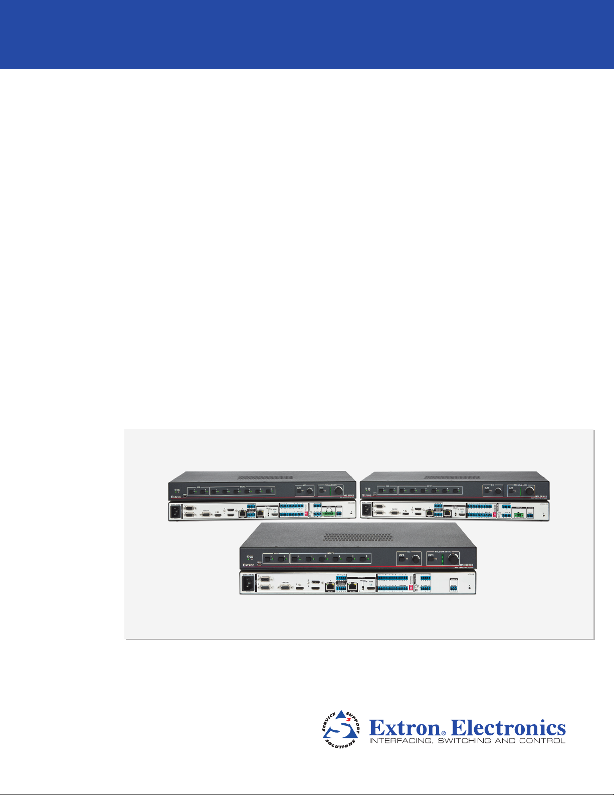
MPS 602
Media Presentation Switcher
User Guide
Switchers
68-2358-01 Rev. A
11 13
Page 2
Safety Instructions
Safety Instructions • English
WARNING: This symbol, , when used on the product, is intended to
alert the user of the presence of uninsulated dangerous voltage within the
product’s enclosure that may present a risk of electric shock.
ATTENTION: This symbol, , when used on the product, is intended
to alert the user of important operating and maintenance (servicing)
instructions in the literature provided with the equipment.
For information on safety guidelines, regulatory compliances, EMI/EMF
compatibility, accessibility, and related topics, see the Extron Safety and
Regulatory Compliance Guide, part number 68-290-01, on the Extron website,
www.extron.com.
Instructions de sécurité • Français
AVERTISSEMENT: Ce pictogramme, , lorsqu’il est utilisé sur le
produit, signale à l’utilisateur la présence à l’intérieur du boîtier du produit
d’une tension électrique dangereuse susceptible de provoquer un choc
électrique.
ATTENTION: Ce pictogramme, , lorsqu’il est utilisé sur le produit,
signale à l’utilisateur des instructions d’utilisation ou de maintenance
importantes qui se trouvent dans la documentation fournie avec le
matériel.
Pour en savoir plus sur les règles de sécurité, la conformité à la réglementation,
la compatibilité EMI/EMF, l’accessibilité, et autres sujets connexes, lisez les
informations de sécurité et de conformité Extron, réf. 68-290-01, sur le site
Extron, www.extron.com.
Sicherheitsanweisungen • Deutsch
WARNUNG: Dieses Symbol auf dem Produkt soll den Benutzer
darauf aufmerksam machen, dass im Inneren des Gehäuses dieses
Produktes gefährliche Spannungen herrschen, die nicht isoliert sind
und die einen elektrischen Schlag verursachen können.
Инструкция по технике безопасности • Русский
ПРЕДУПРЕЖДЕНИЕ: Данный символ, , если указан
на продукте, предупреждает пользователя о наличии
неизолированного опасного напряжения внутри корпуса
продукта, которое может привести к поражению
электрическим током.
ВНИМАНИЕ: Данный символ, , если указан на продукте,
предупреждает пользователя о наличии важных инструкций
по эксплуатации и обслуживанию в руководстве,
прилагаемом к данному оборудованию.
Для получения информации о правилах техники безопасности,
соблюдении нормативных требований, электромагнитной
совместимости (ЭМП/ЭДС), возможности доступа и других
вопросах см. руководство по безопасности и соблюдению
нормативных требований Extron на сайте Extron: www.extron.com,
номер по каталогу - 68-290-01.
Chinese Simplified(简体中文)
警告: 产品上的这个标志意在警告用户该产品机壳内有暴露的危险 电压,
有触电危险。
注意: 产品上的这个标志意在提示用户设备随附的用户手册中有
重要的操作和维护(维修)说明。
关于我们产品的安全指南、遵循的规范、EMI/EMF 的兼容性、无障碍
使用的特性等相关内容,敬请访问 Extron 网站 www.extron.com,参见
Extron 安全规范指南,产品编号 68-290-01。
Chinese Traditional( )
警告: 若產品上使用此符 號,是為了提醒使 用者,產品機殼內存在著
可能會導致觸電之風險的未絕緣危險電壓。
VORSICHT: Dieses Symbol auf dem Produkt soll dem Benutzer in der
im Lieferumfang enthaltenen Dokumentation besonders wichtige Hinweise
zur Bedienung und Wartung (Instandhaltung) geben.
Weitere Informationen über die Sicherheitsrichtlinien, Produkthandhabung,
EMI/EMF-Kompatibilität, Zugänglichkeit und verwandte Themen finden Sie in
den Extron-Richtlinien für Sicherheit und Handhabung (Artikelnummer
68-290-01) auf der Extron-Website, www.extron.com.
Instrucciones de seguridad • Español
ADVERTENCIA: Este símbolo, , cuando se utiliza en el producto,
avisa al usuario de la presencia de voltaje peligroso sin aislar dentro del
producto, lo que puede representar un riesgo de descarga eléctrica.
ATENCIÓN: Este símbolo, , cuando se utiliza en el producto, avisa
al usuario de la presencia de importantes instrucciones de uso y
mantenimiento recogidas en la documentación proporcionada con el
equipo.
Para obtener información sobre directrices de seguridad, cumplimiento
de normativas, compatibilidad electromagnética, accesibilidad y temas
relacionados, consulte la Guía de cumplimiento de normativas y seguridad de
Extron, referencia 68-290-01, en el sitio Web de Extron, www.extron.com.
注意 若產品上使用此符號,是為了提醒使用者,設備隨附的用戶手冊中有重
要的操作和維護(維修)説明。
有關安全性指導方針、法規遵守、EMI/EMF 相容性、存取範圍和相關主題的詳細資
訊,請瀏覽 Extron 網站:www.extron.com,然後參閱《Extron 安全性與法規
遵守手冊》,準則編號 68-290-01。
Japanese
警告: この記号 が製品上に表示されている場合は、筐体内に絶縁されて
いない高電圧が流れ、感電の危険があることを示しています。
注意: この記号 が製品上に表示されている場合は、本機の取扱説明書
に 記載さ れて いる重 要な操 作 と保 守 ( 整 備)の 指 示につ いてユーザ ー の 注
意を喚起するものです。
安全上のご注意、法規厳守、EMI/EMF適合性、その他の関連項目に
つ い て は 、エ ク スト ロン の ウ ェ ブ サ イト www.extron.com よ り 『 Extron Safety
and Regulatory Compliance Guide』 ( P/N 68-290-01) をご覧ください。
Korean
경고: 이 기호 가 제품에 사용될 경우, 제품의 인클로저 내에 있는
접지되지 않은 위험한 전류로 인해 사용자가 감전될 위험이 있음을
경고합니다.
주의: 이 기호 가 제품에 사용될 경우, 장비와 함께 제공된 책자에 나와
있는 주요 운영 및 유지보수(정비) 지침을 경고합니다.
안전 가이드라인, 규제 준수, EMI/EMF 호환성, 접근성, 그리고 관련 항목에
대한 자세한 내용은 Extron 웹 사이트(www.extron.com)의 Extron 안전 및
규제 준수 안내서, 68-290-01 조항을 참조하십시오.
Page 3

FCC Class A Notice
This equipment has been tested and found to comply with the limits for a Class A digital device,
pursuant to part15 of the FCC rules. The ClassA limits provide reasonable protection against harmful
interference when the equipment is operated in a commercial environment. This equipment generates,
uses, and can radiate radio frequency energy and, if not installed and used in accordance with the
instruction manual, may cause harmful interference to radio communications. Operation of this
equipment in a residential area is likely to cause interference. This interference must be corrected at
the expense of the user.
NOTE: This unit was tested with shielded I/O cables on the peripheral devices. Shielded cables
ATTENTION: The Twisted Pair Extension technology works with unshielded twisted pair
must be used to ensure compliance with FCC emissions limits.
For more information on safety guidelines, regulatory compliances, EMI/EMF compatibility,
accessibility, and related topics, see the “Extron Safety and Regulatory Compliance
Guide” on the Extron website.
(UTP) or shielded twisted pair (STP) cables; but, to ensure FCC Class A and CE compliance,
STPcables and STP Connectors are required.
For more information on safety guidelines, regulatory compliances, EMI/EMF compatibility,
accessibility, and related topics, see the “Extron Safety and Regulatory Compliance Guide”
on the Extron website.
Copyright
© 2013 Extron Electronics. All rights reserved.
Trademarks
All trademarks mentioned in this guide are the properties of their respective owners.
The following registered trademarks®, registered service marks
RGBSystems, Inc. or Extron Electronics:
Registered Trademarks
AVTrac, Cable Cubby, CrossPoint, eBUS, EDID Manager, EDID Minder, Extron, Flat Field, GlobalViewer, Hideaway, Inline, IPIntercom, IPLink,
Key Minder, LockIt, MediaLink, PlenumVault, PoleVault, PowerCage, PURE3, Quantum, SoundField, SpeedMount, SpeedSwitch, System
Integrator, TeamWork, TouchLink, V-Lock, VersaTools, VN-Matrix, VoiceLift, WallVault, WindoWall, XTP, and XTP Systems
Registered Service Mark
AAP, AFL (Accu-Rate Frame Lock), ADSP (Advanced Digital Sync Processing), AIS (Advanced Instruction Set), Auto-Image, CDRS (Class D
Ripple Suppression), DDSP (Digital Display Sync Processing), DMI (Dynamic Motion Interpolation), DriverConfigurator, DSPConfigurator, DSVP
(Digital Sync Validation Processing), FastBite, FOXBOX, IP Intercom HelpDesk, MAAP, MicroDigital, ProDSP, QS-FPC (QuickSwitch Front Panel
Controller), Scope-Trigger, SIS, Simple Instruction Set, Skew-Free, SpeedNav, Triple-Action Switching, XTRA, ZipCaddy, ZipClip
(SM)
: S3 Service Support Solutions
Trademarks (™
(SM)
, and trademarks
(®)
)
(TM)
are the property of
Page 4

Conventions Used in this Guide
Notifications
The following notifications are used in this guide:
ATTENTION: Attention indicates a situation that may damage or destroy the product or
associated equipment.
NOTE: A note draws attention to important information.
TIP: A tip provides a suggestion to make working with the application easier.
Software Commands
Commands are written in the fonts shown here:
^AR Merge Scene,,Op1 scene 1,1 ^B 51 ^W^C
[01] R 0004 00300 00400 00800 00600 [02] 35 [17] [03]
E X! *X1&* X2)* X2#* X2! CE}
NOTE: For commands and examples of computer or device responses mentioned
in this guide, the character “0” is used for the number zero and “O” is the capital
letter “o.”
Computer responses and directory paths that do not have variables are written in the font
shown here:
Variables are written in slanted form as shown here:
Selectable items,such as menu names, menu options, buttons, tabs, and field names are
written in the font shown here:
Specifications Availability
Product specifications are available on the Extron website, www.extron.com.
Reply from 208.132.180.48: bytes=32 times=2ms TTL=32
C:\Program Files\Extron
ping xxx.xxx.xxx.xxx —t
SOH R Data STX Command ETB ETX
From the File menu, select New.
Click the OK button.
Page 5

Contents
Introduction............................................................ 1
About this User Guide ........................................ 1
About the MPS602 ............................................ 1
Features ............................................................. 1
Installation ............................................................. 5
Mounting the Switcher ........................................ 5
Rear Panel Connections ..................................... 5
Video Input and Output .................................. 5
DTP Input and Output..................................... 6
Analog Audio Input ......................................... 6
Program Audio Output .................................... 8
Control ports .................................................. 9
Twisted Pair Recommendations .......................... 9
Supported Cables .......................................... 9
Cable Recommendations ............................... 9
LockIt Lacing Bracket ....................................... 10
Cabling the MPS602 Switcher ......................... 11
Operation ............................................................. 12
Front Panel Operation ....................................... 12
Input Switching ............................................. 12
Input Auto Switch ......................................... 13
Audio Controls .............................................. 13
Front Panel Security Lockout
(Executivemode) ......................................... 14
HDMI/DTP Embedded Audio Output ................ 15
Program Audio ................................................. 15
Embedded Audio and Analog Audio ............. 15
Program Audio Breakaway ........................... 15
Fixed Output and Variable Output ................. 15
Mic Mix Control ............................................ 16
Program Audio Volume ................................ 16
Program Audio Mute..................................... 16
Audio Gain and Attenuation Adjustments ...... 17
Microphone Controls .................................... 18
EDID Minder ..................................................... 19
Automatic Mode ........................................... 19
User assigned EDID Mode ........................... 20
HDCP ............................................................... 21
Remote Communication and Control .......... 22
Connection Options .......................................... 22
Remote Control Port (RS-232) ...................... 22
Front Panel Configuration Port ...................... 23
Host-to-MPS Communications ......................... 24
MPS Switcher-initiated Messages ................. 24
MPS Switcher Error Responses .................... 25
Command and Response Table ........................ 25
Using the Command and Response Table .... 25
Reference Information ..................................... 33
Mounting the Switcher ...................................... 33
UL Rack Mounting Guidelines ....................... 34
RackMounting ............................................. 34
Table or WallMounting .................................. 34
DataViewer ....................................................... 35
Updating Firmware ........................................... 36
vMPS602 • Contents
Page 6

MPS602 • Contents vi
Page 7

Introduction
This section describes this guide and features of the MPS602, including:
• About this User Guide
• About the MPS602
• Features
About this User Guide
This guide contains information to install, configure, and operate the Extron Media
Presentation Switcher, MPS602, MPS602 SA, and MPS 602 MA.
In this guide, the MPS602can be referred to as “MPS”, “MPS602” or “switcher”. Where
differences between the models occur, they will be called out.
About the MPS602
The Extron MPS602 series are six input media presentation switchers for digital and
analog sources. It offers digital video switching with three HDCP-compliant HDMI inputs
and one DTP230 twisted pair input, and analog video switching with two RGB inputs
that are digitized for distribution to the digital output. For increased flexibility, the MPS602
includes a DTP 230 twisted pair output and an HDMI output that are switch-selectable. The
DTP230 input and output extend video, audio, and bidirectional control signals to DTP230
transmitters and receivers, each over a single CATx cable up to 230 feet (70 meters). The
MPS 602 also includes several audio switching and processing features, available power
amplification, plus flexible control options for complete switching and distribution with local
and remote display support.
Features
• Internal universal power supply — The 100-240 VAC, 50-60 Hz, international power
supply provides worldwide power compatibility.
• HDMI, RGB, and audio source integration. Supports computer-video to 1920x1200,
including HDTV 1080p/60 Deep Color and 2K.
• Easy setup and commissioning with the Extron Product Configuration Software
(PCS)— Conveniently configures multiple products using a single software application.
• Inputs — Includes three HDMI, one DTP 230 twisted pair input on RJ-45, two RGB
video on 15-pin HD, five stereo balanced/unbalanced audio inputs on captive screw,
one mix audio input on captive screw.
• Outputs — Includes one selectable DTP 230 twisted pair output on RJ-45 or HDMI
output, one RGB video on 15-pin HD, one fixed audio output on captive screw, one
variable stereo audio output on captive screw, speaker outputs on 5 mm, 4-pole
captive screw connector (MPS 602 SA) or on 5 mm, 2-pole captive screw connector
(MPS602MA).
• Three HDMI inputs and two RGB inputs — Allow switching between HDMI and
analog video sources.
MPS602 • Introduction 1
Page 8

• Selectable HDMI or DTP 230 output — Routes the inputs signal to either the HDMI
output or the DTP 230 output.
• Independent RGB input switching — Allows independent switching of RGB inputs to
the local RGB output.
• Integrated DTP 230 input and output support transmission of HDMI or DVI,
control, and analog audio up to 230 feet (70 meters) over a single CATx cable
— Supports digital signal transmission of HDMI or DVI plus control and analog audio up
to 230 feet (70 meters) over a single CATx cable, providing high reliability and maximum
performance on an easily installed cable infrastructure.
• Compatible with CAT 5e, CAT 6, and CAT 7 twisted pair cable — Fully supports
a maximum transmission distance of 230 feet (70 meters) for all compatible resolutions
when used with CAT 5e, CAT 6, CAT 6a, or CAT 7 twisted pair cable. Shielded twisted
pair cabling with solid center conductor sizes of 24 AWG or better is recommended for
optimal performance.
• Extron XTP DTP 24 Shielded Twisted Pair cable — provides added protection from
outside interference and ensures high quality signal transmission.
• Bidirectional RS-232 and IR insertion for AV device control — Transmits
bidirectional RS-232 control and IR signals can be transmitted alongside the video
signal over DTP connections, allowing the remote device to be controlled without the
need for additional cabling. Bidirectional control insertion eliminates the need for control
system wiring to remote devices.
• Remote powering of DTP transmitter and receiver — Provides power to a DTP
230 transmitter and a remote DTP 230 receiver over the CATx connection.
• Compatible with all DTP HDMI 230 and DTP DVI 230 models — Enables mixing
and matching of desktop and wallplate transmitters and receivers to meet application
requirements.
• Digital conversion of analog input signals — Digitizes analog signals, ensuring that
a reliable, high quality digital video signal is sent to the output destination.
• HDCP compliant — Fully supports HDCP-encrypted sources, with selectable
authorization for unencrypted content.
• Supported HDMI specification — Features include data rates up to 6.75 Gbps, deep
color up to 12-bit, 3D, and HD lossless audio formats
• Key Minder — Authenticates and maintains continuous HDCP encryption between
input and output devices to ensure quick and reliable switching in professional AV
environments, while enabling simultaneous distribution of a single source signal to one
or more displays.
• EDID Minder — Ensures that all sources power up properly and reliably output content
for display.
• Supports EDID and HDCP transmission — Actively buffers DDC channels allowing
continuous communication between source and display.
• HDMI audio embedding — Embeds analog input audio signals onto the HDMI output
signal.
• HDMI audio de-embedding — Extracts HDMI two-channel PCM audio to the analog
outputs.
• Mic/line input with 48 volt phantom power — Mixes mic or line level audio source
with program audio. Selectable 48 volt phantom power allows the use of condenser
microphones.
• Mic Talk Over — Automatically reduces program audio when a microphone signal is
detected, replacing the need for a separate standalone audio ducking processor.
MPS602 • Introduction 2
Page 9

• Audio breakaway — Provides the capability to break an analog audio signal away
from its corresponding video signal and route to the audio outputs, allowing the analog
audio channels to be operated as a separate switcher.
• Output volume control — Provides volume control and muting for the program and
amplified audio outputs, as well as a separate control for mic volume and muting.
• Available with energy efficient Class D stereo or mono amplifier:
• 2 x 50 watts @ 4 ohms; 2 x 25 watts @ 8 ohms
• 1 x 100 watts @ 70 volts — The MPS 602 SA offers a stereo power amplifier with
50 watts per channel into 4 ohms and 25 watts per channel into 8 ohms, while the
MPS 602 MA offers a mono 70 volt power amplifier with 100 watts rms output.
Both feature an Extron exclusive, highly efficient, advanced Class D amplifier design
with CDRS - Class D Ripple Suppression, an Extron patented technology that
provides a smooth, clean audio waveform and an improvement in signal fidelity
over conventional Class D amplifier designs. CDRS eliminates the high frequency
switching ripple characteristic of Class D amplifiers, a source of RF emissions which
can interfere with sensitive AV equipment such as wireless microphones.
• Auto-switching between inputs (Auto Switch) — Allows for simple, unmanaged
installation in locations such as in a lectern or under a conference table. When multiple
inputs are active, the switching priority is configurable.
• Front panel security lockout — Locks out either all front panel functions, or mic
volume and muting; all functions however, are available through USB or RS-232 control.
• RS-232 control port — Enables the use of serial commands for complete control
and configuration via the Extron Windows®-based control program, or integrated into
a control system. Extron products use the SIS - Simple Instruction Set command
protocol, a set of basic ASCII commands that allow for quick and easy programming.
• Front panel USB configuration port — Enables easy configuration without having to
access the rear panel.
• RJ-45 signal and link LED indicators for DTP port — Provides a means for
validating signal flow and operation from transmitter or receiver, allowing quick
identification of connectivity issues.
• Rack-mountable 1U, full rack width metal enclosure
• Includes LockIt HDMI cable lacing brackets
MPS602 • Introduction 3
Page 10
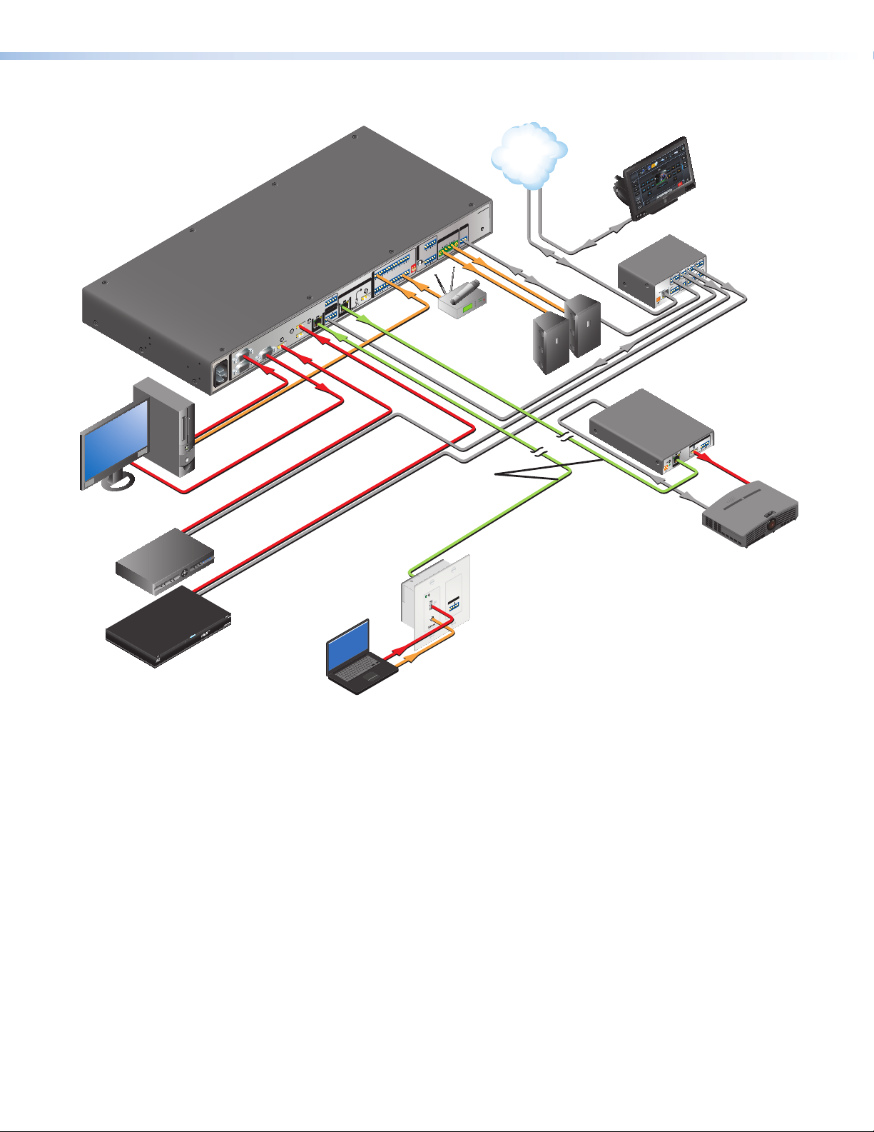
Figure 1 shows a typical application.
IP Link Control
Extron
MPS 602 SA
Media Presentation
Switcher
PC
Local Monitor
100-240V X.XA MAX
50/60 Hz
RGBHV
1
2
INPUTS
Audio
RGB OUT
3
RGBHV
HDMI
TCP/IP
Network
Extron
TLP 1000TV
10" Tabletop
TouchLink
Ethernet
MPS 602 SA
R
REMOTE
RS-232
R
AMP OUT
R
8Ω / 4Ω
PROGRAM
L
L
Tx Rx G
CLASS 2 WIRING
RS-232
Extron
SI 28
Surface
R
FIXED
L 3 R
L
AUDIO OUT
PHANTOM POWER
MUTE HDMI AUDIO
L 2 R
MIC
MIX
L 1 R
MIC LINE
L 5 R
L 4 R
HDMI
AUDIO IN
OUTPUTS
SELECT
RS-232 IR
SIG LINK
Rx GTx Tx Rx
OVER DTP
6
OVER DTP
DTP OUT
RS-232 IR
SIG LINK
Rx GTx Tx Rx
4
DTP IN
5
Wireless
Mic
Ethernet
POWER
12V
500mA
MAX
Mount
Speakers
RS-232
IR
HDMI
IR
CATx Cable
up to 230' (70 m)
RS-232
Touchpanel
Extron
IPL 250
2
RELAY
1
IR
2
1
Processor
COM 2
4
RELAY
TXRX
3
S G S G
COM1
RTS CTS
4
IR
TXRX
3
COM 3
TXRX
S G S G
INPUT
LAN
1 2 3 4
Extron
DTP HDMI 230 Rx
Receiver
AUDIO
OUTPUTS
L R
SIG LINK
POWER
12V
0.7A MAX
HDMI
DTP IN
Projector
Satellite
Receiver
DBS RECEIVER
INPUTS
AUDIO
Extron
DTP HDMI 230 D Tx
IR
OVER DTP
RS-232
TxRx G Tx Rx
Transmitter
HDMI
Blu-ray
Player
Audio
Laptop
Figure 1. MPS602 Application Diagram
MPS602 • Introduction 4
Page 11
Installation
k
n
op s
ab
c
dg
hij
fq
elmr
This section describes the installation and the operation of the MPS602, including:
• Mounting the Switcher
• Rear Panel Connections
• Twisted Pair Recommendations
• LockIt Lacing Bracket
• Cabling the MPS602 Switcher
Mounting the Switcher
The MPS602 is housed in a 1U, full rack widthrack- or desk-mountable metal enclosure.
The switchercan also be surface-mounted under a table, desk, or podium, or on a wall (see
Mounting the Switcher on page33 for additionalmounting details).
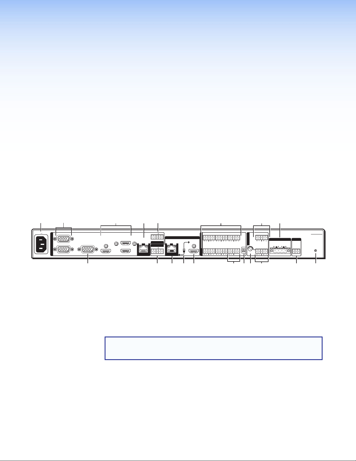
Rear Panel Connections
100-240V 1.0A MAX
50/60 Hz
1
2
INPUTS
RGB OUT
4
3
5
Figure 2. MPS602 Rear Panel
a AC power — Connect to standard AC power: 100 to 240 VAC, at 50 or 60 Hz.
Video Input and Output
b RGB/VGA video input group — Two female 15-pin HD connectors for VGA input that
supports analog RGB video (numbered 1 and 2 on the rear panel).
NOTE: The MPS602 does not scale or convert video, however it does convert an
analog RBG input to digital for the digital outputs. The output signal resolution is
the same as the input resolution.
c RGB video output — One 15-pin HD connector with the selected RGB/VGA video
input.
d HDMI video input group — Three HDMI connectors for HDMI compliant audio and
video input (numbered 3, 4, and 5 on the rear panel). Connect to any HDMI source
device using standard HDMI cables (see LockIt Lacing Bracket on page10).
e HDMI video output — Connect an HDMI display device for output from the selected
HDMI input (see LockIt Lacing Bracket on page10).
6
SIG LINK
DTP IN
RS-232 IR
Rx GTx Tx Rx
OVER DTP
OVER DTP
RS-232 IR
Rx GTx Tx Rx
SIG LINK
DTP OUT
OUTPUTS
SELECT
HDMI
AUDIO IN
L 1 R L 2 R L 3 R
L 4 R L 5 R MIC LINE
MUTE HDMI AUDIO
PHANTOM POWER
AUDIO OUT
MIC
MIX
L VARIABLE R
L FIXED R
AMP OUT REMOTE
8Ω / 4Ω
R
L
CLASS 2 WIRING
RS-232
Tx Rx G
MPS 602 SA
R
MPS602 • Installation 5
Page 12
DTP Input and Output
Slee
f DTP In — Connect a DTP 230 source (Tx) to this RJ-45 jack (numbered 6 on the rear
panel). The DTP input includes the HDMI (or DVI with the proper adapter) video with
embedded audio, bi-directional RS-232 and IR, separate balanced or unbalanced
analog audio, and remote power for a connected DTP Tx device.
g RS-232 and IR Over DTP In — One 3.5mm 5-pole captive screw connector provides
connection for bidirectional RS-232 and remote IR signals between the DTPTx
connected to input 6 (figure 2, f) of the MPS602.
h RS-232 and IR Over DTP Out — One 3.5mm 5-pole captive screw connector to
connect and pass bi-directional RS-232 and IR between the MPS602 and DTP230Rx.
RS-232
To pass bidirectional serial command signals between DTP-compatible devices,
connect a control device to the three leftmost poles (Tx, Rx, and G) of the 5-pole
captive screw connector (see Twisted Pair Recommendations on page9).
IR Over DTP Wiring
To transmit and receive IR signals, connect a control device to the two rightmost poles.
NOTE: RS-232 and IR data can be transmitted or received simultaneously.
i DTP output — Connect an Extron DTP 230 device using this RJ-45 jack. The DTP
230 signal format and protocol is used. The output can include HDMI (with embedded
audio), bidirectional RS-232 and IR, separate analog audio (from the fixed audio output),
and remote power for a connected DTP230 receiver.
j DTP out or HDMI out selection switch — One single-pole double-throw switch to
select either the DTP (i) or HDMI (e) output.
Analog Audio Input
k Audio input group —Five 3.5mm, 5-pole captive screw connectors provide analog
audio input to the switcher. Inputs 1-5 accept either balanced or unbalanced audio. The
audio level of each analog audio input is adjusted using the configuration software or
using the front panel (see Audio Gain and Attenuation Adjustments on page17).
Tip
Ring
ves
Tip
Ring
Balanced Stereo Input
Tip
Sleeve
Tip
Sleeve
Unbalanced Stereo Input
LR
Sleeve
LR
Sleeve
Tip
Ring
Balanced Mono Input
(high impedance)
Tip
Unbalanced Mono Input
Figure 3. Audio Input Wiring
ATTENTION: The audio input group input numbers correspond to the associated
video inputs. Audio inputs 1 and 2 are associated with RGB video inputs 1 and
2. Audio inputs 3, 4, and 5 are associated with HDMI video inputs 3, 4, and 5.
LR
LR
MPS602 • Installation 6
Page 13
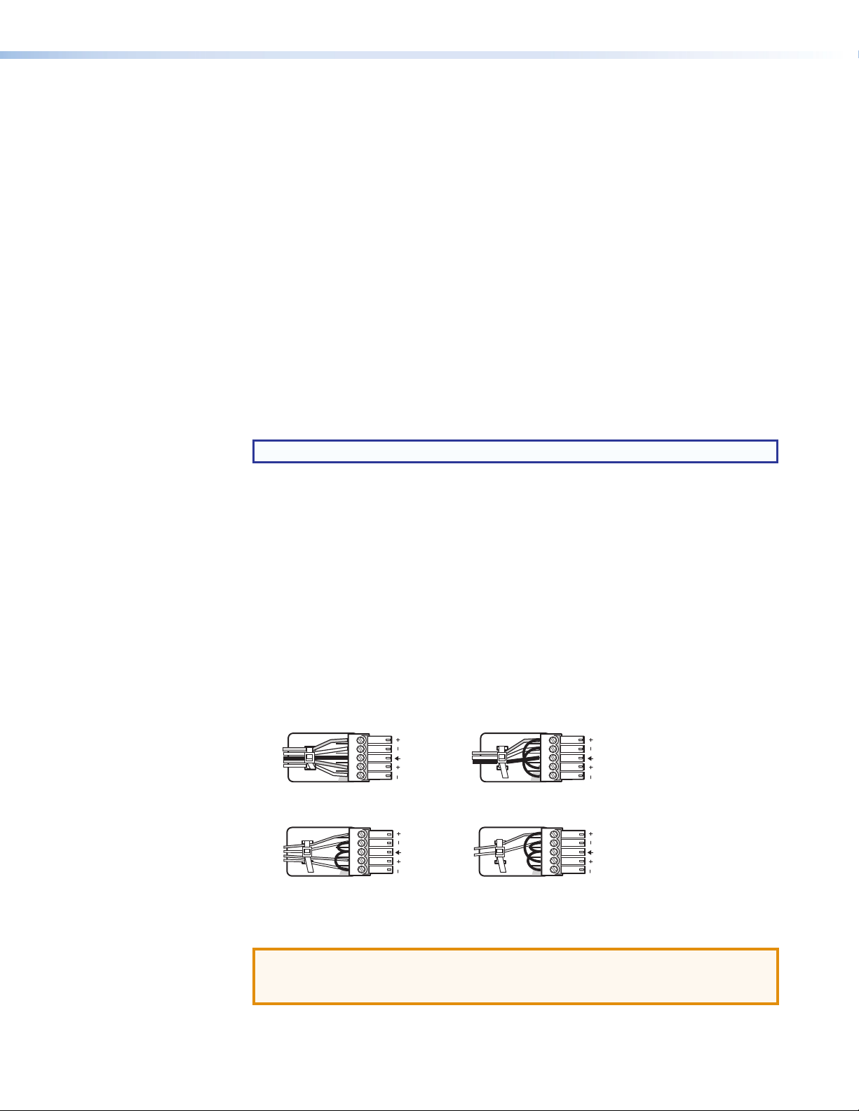
l Mic/Line input — One 3-pole captive screw connector switchable betweenmic
Sleev
L
R
and line level inputs. Wire the connector as shown below (see figure 4). Use the
configuration software to select themic or line input level.
3
"
(5 mm) MAX. (typ)
Tip
Ring
e
Balanced Input
16
Figure 4. 3.5mm, 3-pole Captive ScrewMicrophone Connector
ATTENTION: Do not tin thewire leads before installing into the connector. Tinned
wires are not as secure in the connector and could be pulled out.
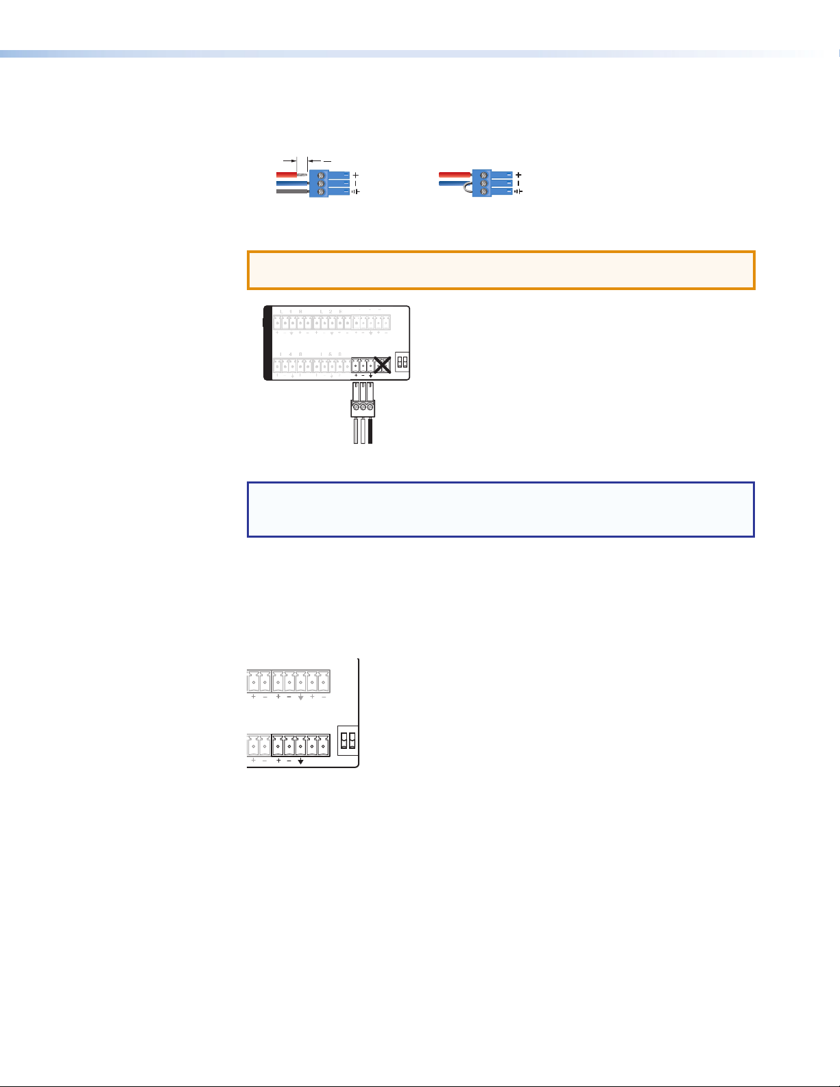
L 3 R
3
AUDIO IN
MIC LINE
Figure 5. Mic/Line Rear Panel Connection
NOTE: Although the rear mic/line input is 5-pole, only 3 poles are used by the
mic/line connector. Be certain to plug the 3-pole mic/line connector into the
correct position.
Tip
Sleeve
Jumper
Unbalanced Input
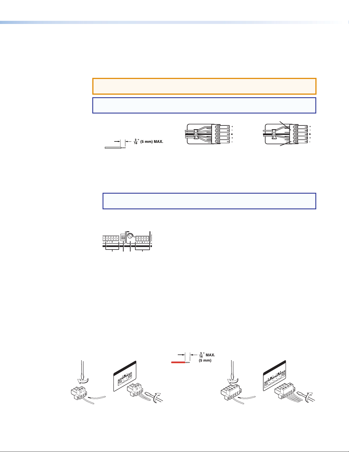
MUTE HDMI AUDIO
PHANTOM POWER
m Mute HDMI Audio and Phantom Power— Two 2-position DIP switches.
The MUTE HDMI AUDIO switch (see figure 6) mutes the HDMI embedded audio on both
the HDMI output and the DTP output when the switch is in the UP position.
The PHANTOM POWER switch selects +48V phantom power for themic input when in
the UP position.
R L 3 R
MUTE HDMI AUDIO
R MIC LINE
PHANTOM POWER
Figure 6. Mute HDMI Audio and Phantom Power DIP Switches
MPS602 • Installation 7
Page 14
Program Audio Output
udio Output
No Ground Here
L
R
RS-232
MPS 602 SA
Tx Rx G
MUTE HDMI AUDIO
PHANTOM POWER
AMP OUT REMOTE
CLASS 2 WIRING
8Ω / 4Ω
AUDIO OUT
L VARIABLE R
R
n
op s
21
21
Connecting the 5-pole captive screw stereo output connector
Balanced or unbalanced program audio output is available on the MPS602 using a 3.5mm,
5-pole captive screw connector. Refer to the following illustration for proper wiring.
ATTENTION: For unbalanced audio output, connect sleeves to the center ground pin.
DO NOT connect sleeves to the negative (–) contacts.
NOTE: Do not tin the audio leads. Tinned wires are not as secure in the connector and
could be pulled out.
Do not tin the wires!
Tip
Ring
Sleeves
Tip
Ring
Balanced Audio Output
LR
Sleeves
Tip
Tip
No Ground Here
Unbalanced A
LR
Figure 7. 3.5mm, 5-pole Captive Screw Audio Output Connectors
n Variable audio output — This 5-pole 3.5mm captive screw connector outputs the
program audio.
NOTE: The variable audio output level is controlled by the front panel volume
encoder.
o Mic Mix — One potentiometer controls the mic/line input level (
) mixed into the fixed
l
audio output (p).
MIC LINE
L FIXED R
MIC
MIX
Figure 8. Mic Mix Level Control
p Fixed audio output — This 5-pole, 3.5mm captive screw connector outputs balanced
or unbalanced fixed level program audio output. The front panel volume encoder
doesnot control the audio level from this audio output port.
1 Strip and insert the speaker wires into the
connector and tighten the captive screws.
Be sure to observe the correct polarit
q Amplified output (MA and SA models only)
MA models — One green 2-pole, 5mm locking captive screw connector for mono 70V
output.
SA models — One green 4-pole, 5mm locking captive screw connector for amplified
dual channel output to a 4 or 8 ohm speaker system.
2 Insert the wired connector into the amplifier
y.
AMP OUT
70V
MPS 602 MA MPS 602 SA
CLASS 2 WIRING
Figure 9. Amplified Output Connector Wiring
Do not tin the wires!
output and secure the locking screws on
either side.
AMP OUT
8Ω / 4Ω
L
CLASS 2 WIRING
MPS602 • Installation 8
R
Page 15

Control ports
RxTx G
r RS-232 remote — A 3-pole, 3.5 mm captive screw connector for connection of a host
computer or a controller using SIS or Windows-based control software.
RS-232
Device
Do not tin
the wires!
Transmit (Tx)
Receive (Rx)
Ground ( _ )
Figure 10. RS-232 Captive Screw Connector Wiring
See Remote Control Port (RS-232) on page22 for additional wiring details.
s Reset button — Recessed button to return the MPS602 to factory default settings.
c USB Configuration Port (front panel) — (see Front Panel Operation on page12)
One mini type-B female USB jack for configuration of the switcher and firmware
upgrades (see Updating Firmware on page36).
Twisted Pair Recommendations
Supported Cables
The MPS602 is compatible with CAT 5e, 6, 6a, and 7 shielded twisted pair (F/UTP, SF/UTP,
and S/FTP) and unshielded twisted pair (U/UTP) cable.
Bidirectional
Transmit (Tx)
Receive (Rx)
Ground ( _ )
ATTENTION:
• Do not use Extron UTP23SF-4 Enhanced Skew-Free AV UTP cable or STP201
cable to link the scaler with DTP transmitters or receivers.
• Do not connect these devices to a computer or telecommunications network.
• DTP remote power is intended for indoor use only. No part of the network that
uses DTP remote power should be routed outdoors.
Cable Recommendations
Extron recommends using the following practices to achieve full transmission distances and
reduce transmission errors.
• Use the following Extron XTP DTP 24 SF/UTP cables and connectors for the best
performance:
• XTP DTP 24/1000 Non-Plenum 1000’ (305 m) spool 22-236-03
• XTP DTP 24P/1000 Plenum 1000’ (305 m) spool 22-235-03
• XTP DTP 24 Plug Package of 10 101-005-02
• If not using XTP DTP 24 cable, at a minimum, Extron recommends 24 AWG, solid
conductor, STP cable with a minimum bandwidth of 400 MHz.
• Terminate cables with shielded connectors to the TIA/EIA-T568B standard.
• Limit the use of more than two pass-through points, which may include patch points,
punch down connectors, couplers, and power injectors. If these pass-through points
are required, use CAT 6 or 6a shielded couplers and punch down connectors.
NOTE: When using CAT 5e or CAT 6 cable in bundles or conduits:
• Do not exceed 40% fill capacity in conduits.
• Do not comb the cable for the first 20 m, where cables are straightened, aligned,
and secured in tight bundles.
• Loosely place cables and limit the use of tie wraps or hook and loop fasteners.
• Separate twisted pair cables from AC power cables.
MPS602 • Installation 9
Page 16

LockIt Lacing Bracket
4
4
4
LockIt lacing brackets are provided to secure the HDMI cables to the rear panel connectors
as shown. The configuration of the HDMI connectors on the MPS602 rear panel require
using a top mount (HDMI input 3) and a single or stacked side mount (HDMI inputs 4 and 5)
installation to secure the three inputs.
To secure a single HDMI cable in HDMI inputs 3 or 4:
1. Loosen the HDMI connection mounting screw from the panel enough to allow LockIt
lacing bracket placement.
ATTENTION:
2. Plug the HDMI cable into the panel connection.
3. Place the LockIt lacing bracket on the screw and against the HDMI connector, then
tighten the screw to secure the bracket.
4. Loosely place the included tie wrap around the HDMI connector (or connectors in a
stacked configuration) and LockIt lacing bracket. Hold the connector securely against
the lacing bracket and tighten the tie wrap, then remove excess length.
To secure two HDMI cables in HDMI inputs 4 and 5:
A single LockIt bracket can secure two HDMI connectors in a stacked configuration as
shown below. In step two above, plug both HDMI cables into the panel and secure both
with the tie wrap in step four.
• Do not remove the HDMI connection mounting screw.
• Do not overtighten the HDMI connection mounting screw. The shield it
fastens to is very thin and can easily be stripped.
5
2
1
3
Top
3
2
4
Side Stacked
4
4
Figure 11. Lockit Lacing Bracket Installation
MPS602 • Installation 10
Page 17

Cabling the MPS602 Switcher
The MPS switcher can be connected to asmany as six input devices. It can output to one
of two outputs (HDMI or DTP). Follow the steps below and the installation example (see the
MPS 602 Application Diagram on page11)
1. Turn off power to the MPS switcher and all devices that will be connected to it.
2. If the MPS switcher is rack, table/wall, or through-deskmounted, position the brackets
and install themounting screws (see Mounting the Switcher on page33).
3. Attach up to two analog, three HDMI (or DVI-D with appropriate adapters) sources,
and one DTP transmitter device to the switcher (see Rear Panel Connections on
page5).
4. Connect the switcher HDMI output to a compatible display device, or the DTP output to
a compatible DTP receiver (see Rear Panel Connections on page5).
5. For stereo audio input, connect up to six audio sources to the corresponding audio
inputs of the analog (1 and 2), HDMI (3 through 5), or DTP (6) video groups (see Rear
Panel Connections on page5).
6. For vocal input, connect a mic to the Mic/line input (see Rear Panel Connections on
page5). Set the phantom power switch if necessary.
7. For output, connect an appropriate audio output device depending on the switcher
model:
• All models – Connect an audio amplifier to the program or fixed Audio Output
connectors (see Rear Panel Connections on page5).
• MPS602SA – Connect stereo speakers to the speaker output connections.
• MPS602MA – Connect a 70V line speaker system to the speaker output
connections.
NOTE: The program and fixed outputs are on all models. On models with
internal amplifiers the outputs are used exactly as they are on non-amplified
models.
8. Connect a control PC or controller to the switcher using:
• The rear panel RS-232 port and a 3-pole captive screw connector (
Remote Control Port (RS-232) on page22).
• The front panel USB configuration port (see Front Panel Configuration Port on
page23).
9. Power up the input and output devices, then connect power to the rear AC connector
of the switcher (see Rear Panel Connections on page5).
k
) (see
MPS602 • Installation 11
Page 18

Operation
This section discusses how to connect, configure, and operate the MPS602. Topics that
are covered include:
• Front Panel Operation
• HDMI/DTP Embedded Audio Output
• Program Audio
• EDID Minder
• HDCP
Front Panel Operation
ab dce ghijklf
EXEC
MODE
CONFIG
RGB
1 2 1 2 3 4 5 6
Input Switching
INPUTS
MICPROGRAM AUDIO
MUTEMUTE
MPS SERIES
MEDIA PRESENTATION SWITCHER
Figure 12. Front Panel Details of the MPS602 Switcher
a Power Indicator — This LED lights when power is applied.
b Executive Mode indicator LED — This red LED lights when Executivemode (front
panel lockout) is active.
c USB Configuration Port — Mini type-B female USB jack for configuration of the
switcher and firmware upgrades.
The controls for the two independent switchers are grouped by input type:
• Analog RGB inputs (1 and 2) routed to the rear panel RGB output (see figure 2 on
page5, c).
• Analog RGB inputs (1 and 2) and digital video inputs (3 through 7) routed to the HDMI
or DTP digital outputs (see figure 2 on page 5, e and i).
NOTE: Audio for the the selected input is routed to all audio outputs. When program
audio breakaway is active (see Program Audio Breakaway on page15), the
input LED corresponding to the breakaway audio blinks while the input LED for the
selected video remains lit solid.
d RGB Inputs (local monitor output) — Buttons 1 and 2 of the RGB input group select
the input for the RGB output. The LEDs to the right of each button (when lit) indicate the
selected RGB input routed to the RGB output.
e RGB Inputs (digital output) — Buttons 1 and 2 of the Inputs group select the input
for the HDMI or DTP output and audio switcher section. The LEDs to the right of each
button (when lit) indicate the selected input.
MPS602 • Operation 12
Page 19

f HDMI (digital output group) — HDMI input buttons 3, 4, and 5 select the input for the
HDMI or DTP output and the corresponding audio switcher section. The LEDs to the
right of each button (when lit) indicate the selected input.
g DTP Input (digital output group)— DTP input button 6 switches a connected DTP
transmitter to the HDMI or DTP output and corresponding audio switcher.
Input Auto Switch
Using software control, the switcher can be configured to automatically switch to the
highest or lowest number input with active video (see Input Auto Switch on page27). If
video is absent from all inputs, input 1 is selected.
Audio Controls
ijkl
MICPROGRAM AUDIO
Figure 13. Front Panel Audio Controls
MUTEMUTE
MPS SERIES
MEDIA PRESENTATION SWITCHER
h Mic Mute — This button toggles themicrophonemixer on and off to provide
microphone talk-over for the program audio. When on (LED lit), the microphone input is
muted for both the program audio output and amplified audio output.
i Mic Volume — This rotary encoder controls the microphone input level mixed into the
program audio output (all models) and amplified audio output (SA and MA models). It
has no effect on the fixed audio output. Rotate the knob clockwise to increase, and
counterclockwise to decrease the volume of themicrophone input. If the mic input is
muted, rotating the Mic volume control unmutes themicrophone.
j Program Audio Mute — This button mutes and unmutes program and amplified
audio. The LED (when lit) indicates program audio ismuted. Whenmuted, inputscan be
switched without unmuting.
k Program Audio Level Indicator — Stacked LEDs indicate the program audio volume
level. All segments unlit indicate no (0) volume. As volume increases, the segments
illuminate incrementally from the bottom and stay lit as illustrated in the table below. As
volume decreases, the LEDs go out in the reverse order.
LED Segment Lit Volume Level
8 (Top LED) 96-100
7 91-95
6 86-90
5 81-85
4 71-80
3 51-70
2 31-50
1 (bottom LED) 1-30
0 (none) 0 (mute)
NOTE: The eight segment program audio LEDs show the real-time output level
whether audio is muted or not.
MPS602 • Operation 13
Page 20

l Program Audio Control — This rotary encoder increases or decreases the variable
MPS SERIES
MEDIA PRESENTATION SWITCHER
MUTEMUTE
MIC PROGRAM AUDIO
for 3 Seconds
through Exec Modes
program audio output (see figure 2 on page 5, n) and the amplified audio output
(MPS602 MA and MPS602SA only, see figure 2 on page 5, q) with this volume
encoder knob. When muted, rotating this knob unmutes the program output.
This control has no affect on the fixed audio output (see figure 2 on page 5, p).
Front Panel Security Lockout (Executivemode)
To prevent unauthorized configuration changes, executivemode limits front panel access.
Control andmonitoring are available using the rear panel RS-232 or front panel USB port
and a connected PC or controller with the control software. The front panel Exec Mode LED
lights red when either lockoutmode is active.
Executivemode contains two modes:
• Mode 1 locks all front panel functions except Executivemode. When Executive mode1
is enabled, the front panel LEDs flash three times. When a front panel adjustment is
attempted, all front panel LEDs flash once.
• Mode 2 locks out the Mic Mute button and Mic Volume control. When Executive mode
2 is enabled, the Mic Mute LED flashes three times. When active, ifmic volume is
changed or themute button pressed, theMicMute LED flashes once.
To toggle through the executivemodes:
1. Press and hold theRGB input 1 (analog group) button formore than 3 seconds.
2. Press the input1 (digital group) button to toggle through the executivemodes.
a. If executivemode is not active (ExecMode LED off), the switcher toggles to
executivemode1, the Mic Mute LED flashes three times, and the ExecMode LED
turns on. Release both buttons to enter executivemode 1.
b. When already inmode 1, the switcher toggles tomode 2 and the ExecMode LED
remains on. All front panel LEDs flash three times. Release both buttons to enter
executivemode 2.
c. Inmode 2, the switcher exits executivemode and turns off the ExecMode LED.
Release both buttons to exit executivemode.
Figure 14. Toggle Executive Modes
EXEC
MODE
CONFIG
Press and Hold
RGB
1 2 1 2 3 4 5 6
Press to Toggle
INPUTS
MPS602 • Operation 14
Page 21

HDMI/DTP Embedded Audio Output
By default, the original embedded audio present on the selected HDMI or DTP input is
routed to the selected HDMI or DTP audio output. If an RGB input is selected there will be
no audio output. Optionally, program audio can be routed to the embedded output instead
(see Audio Routing on page29).
NOTE: If the sink device connected to the DHMI/DTP output is DVI, then the signal is
converted to DVI format automatically. This results in no embedded audio output.
HDMI Audio Mute
The HDMI or DTP embedded audio output can be muted permanently by setting the
MuteHDMIAudio dip switch (see figure 2 on page 5, j)
Program Audio
The selected audio input is simultaneously switched to the program variable audio output,
fixed audio output, and the volume level of the amplifier (MA and SA only). The front panel
input LED selected for program audio output blinks.
Embedded Audio and Analog Audio
If the selected HDMI or DTP input has embedded audio, the switcher extracts the digital
audio and converts it to analog for program audio output, fixed audio out, and amplfiied
audio output (MA and SA only). If there is no embedded digital audio, the switcher selects
the current input analog audio (see figure 2, k, on page5).
NOTE: When the selected input has both embedded digital audio and analog audio
available, by default the switcher extracts the embedded digital audio for the audio
outputs. Using SIS commands, the default can be changed to select the analog
audio input instead. This is individually configured for each HDMI input .
Program Audio Breakaway
Program audio breakaway allows routing of the audio signal from any input to the program
audio output independently from the input video signal. It is available by software control
only (see Program audio breakaway on page29). For the HDMI or DTP inputs, the
analog audio input must selected, also by software control.
NOTE: Digital (embedded) audio cannot be broken away from the digital source.
By default, the HDMI or DVI inputs cannot be broken away to or from, unless first
configured to use the analog input.
Fixed Output and Variable Output
The balanced and unbalanced wiring of inputs and outputs result in different audio levels.
Refer to the following table for fixed output audio levels based on input and output wiring.
Input Wiring Output Wiring Audio Output Level
Unbalanced Unbalanced 0dB
Unbalanced Balanced +6dB
Balanced Balanced 0dB
Balanced Unbalanced -6dB
MPS602 • Operation 15
Page 22

Mic Mix Control
The Mic mix knob simultaneously adjusts the mic volume mixed into the program audio
output and into the amplified audio output. It has no effect on the fixed audio output. Rotate
clockwise to increase mic volume and counterclockwise to decrease.
Program Audio Volume
Use the front panel rotary encoder knob to increase or decrease
program volume. Program volume adjustment has no effect on
the mic volume so program audio can bemuted while the mic
input is still active. The program audio volume has a range from
0-100 allowing the switcher to be controlled with a MediaLink
controller. The associated LEDs light from bottom to top with
increasing volume (see Audio Controls on page13).
Program Audio Mute
The Program Audiomute button toggles output audio on and off. The indicator LED to the
right of the button lights red when program audio ismuted. Press themute button again to
unmute the output.
NOTES:
• Program audiomute does notmute themicrophone input.
• Changing the audio input selection does not unmute the program audio output.
• Changing the program audio control knob unmutes the program audio output.
MUTE
PROGRAM AUDIO
MPS SERIES
MEDIA PRESENTATION SWITCHER
MPS602 • Operation 16
Page 23

Audio Gain and Attenuation Adjustments
Front Panel LEDs
19
+18
+17
+16
+15
+14
+13
+12
+11
+10
+24
+23
+22
+21
+20
+19
19
Each audio input level (analog inputs 1 through 5 only)
is adjusted from the front panel over a range of -18 dB
to +24 dB. The adjustments normalize the input audio
levels so that output volume is consistent for all inputs.
The front panel input indicator LEDs provide a status
of the current input gain or attenuation level. When
adjusting the audio level, the inputs 1 and 2 (RGB inputs
1 and 2) and inputs 1 through 6 function as indicators of
the current audio level for the selected input as shown in
the table.
Gain or attenuation is indicated by the red Exec Mode
LED. Off indicates gain (+ dB) or zero. On indicates
audio is attenuated (- dB).
To adjust the input audio level from the
front panel:
1. Press and hold the Program Audio Mute and
Micmute buttons for 3 seconds (see figure 11 on
page 12). The two Mute LEDs flash three times as
the adjustment mode is enabled.
2. Press the input button for the desired audio
level adjustment. If no input button is pressed,
the switcher times out and exits the audio input
adjustmentmode.
3. When the input is selected, the front panel LEDs
indicate the current gain or attenuation setting for
that input. Factory default is 0dB (all nine LEDs
off). Rotate the program volume knob clockwise
to increase and counterclockwise to decrease the
audio level. The LEDs display the level as the knob
is rotated.
4. Once the desired level is achieved, to adjust another
input, select it within 3 seconds.
If audio adjustments are complete:
a. Do not press any front panel buttons for at least
3 seconds to exit the adjustmentmode, or
b. Press the Program audio and Micmute buttons
simultaneously to exit the adjustmentmode.
At any time during the adjustments, if front panel
buttons are not pressed or the program audio knob is
not rotated within 3 seconds, the switcher times out and
the audio adjustmentmode is exited.
VGA Input 1
VGA Input 2
Input 1
Input 2
5
dB
+9
+8
+7
+6
+5
+4
+3
F
+2
S
+1
0
S
-1
F
-2
-3
-4
-5
-6
-7
-8
-9
-10
-11
-12
-13
-14
-15
-16
-17
-18
= on = off
= blinking fast = blinking slow
F
432
F
S
F
S
F
S
F
S
S
F
S
F
S
F
S
F
Input 3
S
6
F
S
S
F
Input 4
7
F
S
Input 5
8
F
S
8765432
Input 6
Exec Mode
MPS602 • Operation 17
Page 24

Microphone Controls
MPS 409
DIGITAL MEDIA PRESENTATION SWITCHER
MUTE
PROGRAM AUDIO
Mic Mute and Volume
Mic volume andmute are controlled from the front panel. The micmute button toggles the
mic input on or off. The corresponding red LED lights when mic volume is disabled (muted).
When the mic input is unmuted (enabled), it ismixed with the program audio output at a
level set by the mic volume rotary encoder. Mic volume is adjusted at a rate of 1dB per
step of the control. Clockwise rotation increases and counterclockwise decreases the mic
volume.
MIC
MUTE
Figure 15. Mic Volume andMute
Talk-over
The MPS602 also features talk-over to automatically reduce program audio volume
whenmicrophone audio is present. When the switcher detects an audio signal from the
Mic input, it immediately reduces or "ducks" the program audio volume. Whenmicrophone
audio is not detected for a period of onesecond, it increases the program audio level at a
rate of 3 dB per second until the program audio returns to the original volume level.
Ducking is adjustable from 0 – 30dB (default is 6dB) through SIS control only. Mic level
threshold, the level at which ducking is initiated, is adjusted from 0 – 30dB through SIS
control only (see Mic talk-over threshold on page30).
Settingmic talk-over threshold
Microphone threshold and program audio ducking levels can only be adjusted using RS-232
or USB control (see Remote Communication and Control on page22).
1. Adjust program audio for nominal listening levels.
2. Turn on themicrophone by pressing the Mic Mute button (mute LED goes out).
3. Speak into themicrophone in a normal voice. Themain program level drops
immediately.
a. If themicrophone consistently cuts off the beginning of speech, or cuts out sections
of audio, adjust the threshold level using RS-232 control (see Mic talk-over
threshold on page30).
b. If the program level is too high during talk-over, but is the proper level for times
where talk-over is not active, adjust the ducking level (see Program audio
ducking level in talk-overmode on page29).
4. Stop speaking into themicrophone. Themain program audio gradually (within 2to4
seconds) increases to the previous level. If not, increase the threshold level (see Mic
talk-over threshold on page30).
MPS602 • Operation 18
Page 25

EDID Minder
Automatic Mode
The digital and analog groups feature EDID Minder, ensuring that each input source reads
the EDID of the output display even when the input is not selected. The result is the video
source powers up properly and reliably outputs content when selected. The EDID remains in
the selectedmode (automatic or user assigned) even after loss of power.
Depending on the EDID mode selected, the EDID of the connected display is stored
automatically in slot 57 (RGB) or slot 58 (HDMI/DTP), or the user manually selects an EDID
file from an internal list. Whether stored automatically or manually, the EDID file is written to
an EEPROM for each input.
If an output display has never been connected, a default EDID file is placed on the RGB,
HDMI, and DTP inputs according to the following table:
Input Group Default EDID
RGB 1280x720 @ 60 Hz
HDMI and DTP 720p @ 60 Hz, 2-ch audio
When a display is connected to an output, the EDID of that display device is read and
replaces the default EDID on each input. The EDID remains even if the display is removed.
If a different display is connected or a user assigned EDID is selected, the previous EDID is
overwritten.
MPS602 • Operation 19
Page 26

User assigned EDID Mode
Using SIS commands, an EDID file can be selected from a table of 56 EDID files. Six
additional EDID file locations are reserved for user-loaded EDID files for the RGB and
HDMI/DVI/DTP inputs. Once a user assigned EDID is selected, it is stored at that input and
EDID polling ceases for a connected display. The following table lists the native resolution of
each factory EDID file.
SIS
Variable
X1^
1 800 x 600 60 Hz PC VGA N/A
2 1024 x 768 60 Hz PC VGA N/A
3 1280 x 720 60 Hz PC VGA N/A
4 1280 x 768 60 Hz PC VGA N/A
5 1280 x 800 60 Hz PC VGA N/A
6 1280 x 1024 60 Hz PC VGA N/A
7 1360 x 768 60 Hz PC VGA N/A
8 1366 x 768 60 Hz PC VGA N/A
9 1400 x 1050 60 Hz PC VGA N/A
10 1440 x 900 60 Hz PC VGA N/A
11 1600 x 900 60 Hz PC VGA N/A
12 1600 x 1200 60 Hz PC VGA N/A
13 1680 x 1050 60 Hz PC VGA N/A
14 1920 x 1080 60 Hz PC VGA N/A
15 1920 x 1200 60 Hz PC VGA N/A
16 2048 x 1080 60 Hz PC VGA N/A
17 800 x 600 60 Hz PC DVI N/A
18 1024 x 768 60 Hz PC DVI N/A
19 1280 x 720 60 Hz PC DVI N/A
20 1280 x 768 60 Hz PC DVI N/A
21 1280 x 800 60 Hz PC DVI N/A
22 1280 x 1024 60 Hz PC DVI N/A
23 1360 x 768 60 Hz PC DVI N/A
24 1366 x 768 60 Hz PC DVI N/A
25 1400 x 1050 60 Hz PC DVI N/A
26 1440 x 900 60 Hz PC DVI N/A
27 1600 x 900 60 Hz PC DVI N/A
28 1600 x 1200 60 Hz PC DVI N/A
29 1680 x 1050 60 Hz PC DVI N/A
30 1920 x 1080 60 Hz PC DVI N/A
31 1920 x 1200 60 Hz PC DVI N/A
32 2048 x 1080 60 Hz PC DVI N/A
Native
Resolution
Refresh Rate Type
Video
Format
Audio
MPS602 • Operation 20
Page 27

SIS
Variable
X1^
33 800 x 600 60 Hz PC HDMI 2-Ch
34 1024 x 768 60 Hz PC HDMI 2-Ch
35 1280 x 768 60 Hz PC HDMI 2-Ch
36 1280 x 800 60 Hz PC HDMI 2-Ch
37 1280 x 1024 60 Hz PC HDMI 2-Ch
38 1360 x 768 60 Hz PC HDMI 2-Ch
39 1366 x 768 60 Hz PC HDMI 2-Ch
40 1400 x 1050 60 Hz PC HDMI 2-Ch
41 1440 x 900 60 Hz PC HDMI 2-Ch
42 1600 x 900 60 Hz PC HDMI 2-Ch
43 1600 x 1200 60 Hz PC HDMI 2-Ch
44 1680 x 1050 60 Hz PC HDMI 2-Ch
45 1920 x 1200 60 Hz PC HDMI 2-Ch
46 2048 x 1080 60 Hz PC HDMI 2-Ch
47 480p 60 Hz HDTV HDMI 2-Ch
48 576p 50 Hz HDTV HDMI 2-Ch
49 720p 50 Hz HDTV HDMI 2-Ch
50 720p 60 Hz HDTV HDMI 2-Ch
51 1080i 50 Hz HDTV HDMI 2-Ch
52 1080i 60 Hz HDTV HDMI 2-Ch
53 1080p 50/25 Hz HDTV HDMI 2-Ch
54 1080p 50 Hz HDTV HDMI 2-Ch
55 1080p 60/24 Hz HDTV HDMI 2-Ch
56 1080p 60 Hz HDTV HDMI 2-Ch
57 Autodetect (VGA Output)
58 Autodetect (HDMI/DTP Output)
59 User loaded slot 1
60 User loaded slot 2
61 User loaded slot 3
62 User loaded slot 4
63 User loaded slot 5
64 User loaded slot 6
NOTE: 2-Ch supports: 2-Ch LPCM audio
Native
Resolution
Refresh Rate Type
Video
Format
Audio
HDCP
If the display connected to the RGB (VGA) output of the switcher does not support DDC, or
the switcher does not obtain EDID from the output, the default resolution (EDID2) is used.
The HDMI inputs and output are HDCP compliant. Connected source devices (that require
HDCP) authenticate with the HDMI inputs individually, regardless of the current input
selection. The HDMI output authenticates with the connected sink device when an HDCP
authenticated HDMI input is selected.
MPS602 • Operation 21
Page 28

Remote
51
5
1
Communication and
Control
This section discusses SIS programming and control of the MPS602 including:
• Connection Options
• Host-to-MPS Communications
• Command and Response Table
Connection Options
The MPS602 can be remotely connected via a host computer or other device (such as a
control system) attached to the rear panel RS-232 port or the front panel USB Config port.
The switcher can be set up and controlled using Simple Instruction Set (SIS) commands.
SIS commandsare executed using the Extron DataViewer program, found at
www.extron.com.
Remote Control Port (RS-232)
The RS-232 port connector (see figure 2, r on page 5) connects to a host or external
controlling device, such as a computer or control system, which can generate the proper
command codes and recognize switcher responses.
The RS-232 connector on the PC is a 9-pin D female with the following pin designations:
Pin RS-232 Function Description
1 - No connection
2 Tx Transmit data
3 Rx Receive data
4 - No connection
5 Gnd Signal ground
6,7 - No connection
8,9 - No connection
The protocol for the serial port is as follows: 9600 baud, no parity, 8 data bits, 1 stop bit, no
flow control. Commands and responses for programming the MPS602 from a host system
connected to the RS -232 or USB port are listed later in this chapter.
9
6
Female Male
6
9
MPS602 • Remote Communication and Control 22
Page 29

Front Panel Configuration Port
The mini type B USB port is located on the front panel (see figure 12 on page 12). It is used
to connect to a host computer for configuration using SIScommands with DataViewer or for
updating firmware with the Firmware Loader utility. Both are available at www.extron.com.
The programs are also necessary to install the USB driver to the connected computer.
To connect the MPS602 to a host computer:
NOTE: If an Extron USB device has never been connected to the host computer, prior
to connecting the MPS602 Config (USB) port for the first time, you must install and
activate the USB driver. The simplest way to do this is to install either Dataviewer
(see DataViewer on page35) or the Firmware Loader utility (see Updating
Firmware on page36).
1. After the USB driver is loaded, connect a USB A to mini B cable between the Config
port on the MPS602 front panel and a USB port of the PC.
Mini Type B
USB
USB Cable
RGB
EXEC
1 2 1 2 3 4 5 6
MODE
CONFIG
Type A
USB
INPUTS
USB
Ports
Computer
MICPROGRAM AUDIO
USB 1
MUTEMUTE
MPS SERIES
MEDIA PRESENTATION SWITCHER
Figure 16. Connecting a PC to the MPS602 Front Panel USB Port
2. If this is the first time an Extron product is connected to the PC, the Found New
Hardware Wizard dialog opens. The first screen offers to connect to Windows Update
to search the Web for the appropriate driver. This is not necessary if the USB driver is
already on your PC (see the Note above).
Found New Hardware Wizard
Welcome to the Found New
Hardware Wizard
Windows will search for current and updated software by
looking on your computer, on the hardware installation CD, or on
the Windows Update Web site [with your permission].
Read our privacy policy
Can Windows connect to Windows Update to search for
software?
Ye s, this time only
Ye s, now and every time I connect a device
No, not this time
2
Click Next to continue
3
Next > Cancel
Figure 17. Found New Hardware Wizard
Select No, not this time if the driver is already on the PC (see the Note above).
3. Click Next.
MPS602 • Remote Communication and Control 23
Page 30

The following dialog opens:
Found New Hardware Wizard
Welcome to the Found New
Hardware Wizard
This Wizard helps you install software for:
Extron USB Device
If your hardware came with an installation CD
or floppy disk, insert it now.
What do you want the wizard to do?
Install the software automatically [Recommended]
4
Install from a list or specific location [Advanced]
Click Next to continue
Next > Cancel
5
Figure 18. Install the Software Automatically
4. Select Install the software automatically (Recommended).
NOTE: You do not need to insert an installation disc.
5. Click Next.
The PC locates the driver and installs it.
6. When the Completed dialog opens, click Finish to close the wizard.
NOTE: The wizard opens only on the first occasion you connect the MPS602 to
a USB port. The wizard reopens only if you connect the MPS602 to a different
USB port or if you connect a different piece of equipment, requiring a different
driver, to the same USB port.
7. Configure the MPS602 as required.
Host-to-MPS Communications
MPS Switcher-initiated Messages
The MPS switcher accepts SIS commands through the RS-232 or USB configuration port.
SIS commands consist of one ormore characters per command field. They do not require
special characters to begin or end the command character sequence. Each response to an
SIS command ends with a carriage return and a line feed (CR/LF = ]), which signals the
end of the response character string. A string is one ormore characters.
When a local event occurs, such as a front panel operation, the MPS switcher responds
by sending amessage to the host. The MPS602-initiatedmessages are listed below
(underlined).
Boot-upmessages
(c) Copyright 20 nn, Extron Electronics, MPS 602, Vx.xx
The copyrightmessage is initiated by the switcher when it is first powered on and
connected using the RS-232 serial connector. Vx.xx is the firmware version number.
]
Status changemessages
The switcher-initiated status changemessages are a result of front panel operations (actual
or software-simulated). The status changemessages are the same as switcher responses
to certain commands (see the last column of the command and response tables starting on
page 27).
MPS602 • Remote Communication and Control 24
Page 31

MPS Switcher Error Responses
ASCII to Hex Conversion Ta ble
Space
When the MPS switcher receives an SIS command and determines that it is valid, it
performs the command and sends a response to the host device. If the switcher is unable
to perform the command because the command is invalid or contains invalid parameters, it
returns an error response to the host. The error response codes are:
E01 ] — Invalid input channel number (too large)
E10 ] — Invalid command
E13 ] — Invalid value (out of range)
Command and Response Table
Using the Command and Response Table
The command and response table is shown on the following pages. Symbols are used
throughout the table to represent variables in the command and response fields. Symbol
definitions and an ASCII-to-hexadecimal (HEX) conversion table are shown below.
Command and response examples are shown throughout the table.
NOTE: Upper and lower case text can be used interchangeably unless otherwise stated.
•
Symbol definitions
=
CR/LF (carriage return/line feed) (hex 0D 0A)
=
Carriage return (no line feed, hex 0D)
Space character in command or response (all other spaces shown are for clarity)
=
•
=
Escape key (hex 1B)
HDMI/DTP audio output select
=
0 = Embedded audio
1 = Analog audio
Video output select
=
1 = RGB
2 = HDMI/DTP
Status
=
0 = off/disabled, 1 = on/enabled
Mic gain in 1 dB steps
=
0 to 60
Mic attenuation in 1 dB steps
=
1 to 18
Mic level in 1 dB steps
=
– 18 to +60,
Mic talk-over threshold level in dB
=
0 to 30, default = 8
Program volume adjustment range
=
0 to 100
| or }
W or
]
E
X!
X@
X#
X$
X%
X^
X*
X1)
MPS602 • Remote Communication and Control 25
Page 32

=
X1!
X1@
X1#
X1$
X1%
X1^
X1&
X1*
X1(
X2)
X2!
X2@
X2#
X2%
X2^
X2&
X2*
X3)
X3!
X3@
X3$
Input select 0 through 6 (0 =deselect)
=
Program audio ducking level in talk-overmode in dB (0 to 30,0 = off)
=
Audio input gain/attenuation in dB (-18 to +24, in 1 dB steps)
=
Audio input gain in dB (0 to 24, in 1 dB steps)
=
Audio input attenuation in dB (1 to 18, in 1 dB steps)
EDID slot number from lookup table (see User assigned EDID Mode on page20):
=
1-56 = factory EDIDs,
57 = VGA automatic mode slot (default for VGA inputs)
58 = HDMI/DTP automatic mode slot (default for HDMI/DTP inputs)
59-64 = user loaded EDID slots
=
Raw EDID HEX value: 128 or 256 Byte (text form)
= EDID native resolution and refresh rate
Device name (default: MPS-602)
=
Name is a text string of up to 24 alpha-numeric characters and a minus sign or hyphen (-). No
blank or space characters are permitted. No distinction between upper and lower case. The first
letter must be a letter, and the last character must not be a minus sign or hyphen.
Input HDCP status:
=
0= No source connected
1=Source connected and is HDCP compliant
2=Source connected but no HDCP
Output HDCP status:
=
0= No sink detected
1=Sink detected with HDCP
2=Sink detected with no HDCP
Input audio format:
=
0=Extract embedded digital audio
1=Use analog audio input instead of embedded digital audio
2=Auto select. Embedded audio takes priority over analog audio.
Executive mode state:
=
0=off
1=front panel lockout
2=mic only lockout
48V phantom power
=
0=off
1=on
HDMI audio mute
=
0=off/unmuted (default)
1=on/muted
Video output selection switch status
=
0=DTP
1=HDMI
Input auto switch mode
=
0=disabled (default)
1=enabled (highest active input has priority)
2=enabled (lowest active input has priority)
Pixel phase
=
0 to 63 (default=32)
Total pixels
=
+255 of the default value depending on input rate
Horizontal or vertical start
=
0 to 255 (default=128)
Verbose mode
=
0=clear/none.
1=verbose mode (default).
2=tagged response for queries.
3=verbose mode and tagged response for queries.
MPS602 • Remote Communication and Control 26
Page 33

Command/response table for SIS commands
Command ASCII Command
(host to switcher)
Response
(switcher to host)
Description
Input selection
Select video and audio input
View current input
Select video input only
NOTE: Video breakaway to the HDMI/DTP inputs (
input.
View video selection
Select RGB input to local RGB
output
View current RGB input to local
RGB output
View video signal presence
X1!
! In
!
X1!
% In
X1!
=3 through 6) is only available when the input is configured to use the analog audio
%
X1!
& In
&
E
}
0LS
X1! •
All ] Select input
X1! ]
X1! •
X1! ]
X1! •
]
Vid
] X1!
RGB
X1! ] X1!
SigX# • X# • X# • X# • X# • X# * X# • X#
View active input
Select input
View input
= input 1 or 2 only
= input 1 or 2 only
Each X# variable represents one
video input from 1 to 6 in order, plus
the RGB and HDMI outputs
0=no signal
1=signal present
X1!
]
X1!
X1!
video only.
audio and video.
X1!
.
video only.
Video Mute
Set video mute
Read video mute
X#
B/b Vmt X#
B/b
X# ] X#
]
Mute HDMI or DTP video output.
= 0=off (unmuted)
1=on (muted)
Input Auto Switch
Disable input auto switch
Priority to highest active input
Priority to lowest active input
View auto switch setting
E
E
E
E
}
0AUSW
}
1AUSW
}
2AUSW
} X2* ]
AUSW
Ausw0
Ausw1
Ausw2
]
]
]
Manual input switching (default)
NOTES: X# = Status 0= off/disabled, 1= on/enabled
X1!
= Input select 1 to 6, 0=deselected
X2*
= Input auto switch 0=disabled (default)
1=enabled, highest active input has priority
2=enabled, lowest active input has priority
MPS602 • Remote Communication and Control 27
Page 34

Command ASCII Command
(host to switcher)
Picture Adjustments (RGB Inputs only)
Set pixel phase
Increment pixel phase value
Decrement pixel phase value
View pixel phase value
Set total pixels value
Increment total pixels value
Decrement total pixels value
View total pixels value
Set horizontal start value
Increment horizontal start value
Decrement horizontal start value
View horizontal start value
Set vertical start value
Increment vertical start value
Decrement vertical start value
View vertical start value
EX1!*X3)
EX1!
+PHAS
EX1!
-PHAS
EX1!
PHAS
EX1!*X3!
EX1!
+TPIX
EX1!
-TPIX
EX1!
TPIX
EX1!*X3@
EX1!
+HSRT
EX1!
-HSRT
EX1!
HSRT
EX1!*X3@
EX1!
+VSRT
EX1!
-VSRT
EX1!
VSRT
}
PHAS
}
}
} X3) ]
}
TPIX
}
}
} X3! ]
}
HSRT
}
}
} X3@ ]
}
VSRT
}
}
} X3@ ]
Response
(switcher to host)
X1!*X3) ]
Phas
X1!*X3) ]
Phas
X1!*X3) ]
Phas
X1!*X3! ]
Tpix
X1!*X3! ]
Tpix
X1!*X3! ]
Tpix
X1!*X3@ ]
Hsrt
X1!*X3@ ]
Hsrt
X1!*X3@ ]
Hsrt
X1!*X3@ ]
Vsrt
X1!*X3@ ]
Vsrt
X1!*X3@ ]
Vsrt
Description
X1!
X1!
to
to
X3@
X3)
X1!
X3!
X1!
X3@
.
.
X1!
.
of
of
Set pixel phase of input
.
X3!
X3@
X3@
to
to
.
to
to
.
X1!
X1!
.
X3!
.
X3@
X3@
.
X3@
X3@
pixel phase to
pixel phase to
X3)
of input
for input
.
.
.
.
Increase input
X3)
.
Decrease input
X3)
.
View pixel phase
Set total pixels of input
Increase the total pixels for input
X3!
to
Decrease the total pixels for input
X1!
to
View total pixels
Set the horizontal start value of input
X1!
to
Increase the horizontal start value of
X1!
input
Decrease the horizontal start value of
X1!
input
View the horizontal start value
X1!
input
Set the vertical start value of input
X1!
to
Increase the vertical start value for
X1!
input
Decrease the vertical start value for
X1!
input
View the vertical start value
X1!
input
.
NOTES:
X1!
= Input select 1 or 2 for RGB
X3)
= Pixel phase 0 to 63 (default=32)
X3!
= Total pixels +255 of default value depending on input rate
X3@
= Horizontal or vertical start 0 to 255 (default=128)
MPS602 • Remote Communication and Control 28
Page 35

Command ASCII Command
(host to switcher)
Response
(switcher to host)
Description
Audio Routing
Set input audio format
View input audio format
Set output HDMI/DTP audio
format
View output HDMI/DTP format
EIX1!*X2@
EIX1!
EO*X!
E
AFMT
AFMT
} X! ]
O AFMT
}
AFMT
AfmtI*
} X2@ ]
}
AfmtO*X!
X2@ ] X1!
View audio format
]
Set output audio format to X!.
View output audio format.
= HDMI inputs 3 through 6 only
X2@
of input
X1!
.
Program audio gain and attenuation (case-sensitive)
Set gain to specific value
Set attentuation to specific
value
Increment level of specific input
Decrement level of specific
input
View audio level of specific
input
X1!*X1$
X1!*X1%
X1!
X1!
X1!
G In
g In
+G In
– G In
G
X1!
X1!
X1!
X1!
X1# ]
• Aud
• Aud
• Aud
• Aud
X1# ]
X1# ]
X1# ]
X1# ]
Set input
Set input
Increment input
Decrement input
View the level
X1!
gain to
X1!
attenuation to
X1#
X1$
X1!
gain by 1 dB.
X1!
gain by 1 dB.
of input
.
X1%
X1!
.
.
Program audio ducking level in talk-overmode
Set audio ducking level
Increment audio ducking
Decrement audio ducking
View audio ducking level
X1@
*58# Adl
+*58#
–*58#
58#
X1@ ]
X1@ ]
Adl
X1@ ]
Adl
X1@ ]
Adjusts howmuch the program
audio ducks (automatically
decreases) in talk overmode.
0 = ducking off.
Increment ducking by 1 dB.
Decrement ducking by 1 dB.
View the ducking level
X1@
.
Program audio breakaway
Select program audio input
only
View current selected audio
input
NOTE: Program audio breakaway to the HDMI/DTP inputs (
for analog audio.
X1!
$ Pra•
$
X1!
X1! ] X1!
=1 to 6 only (analog audio input)
X1! ]
=3 through 6) is only available when the audio input format is configured
Volume level
Specify volume variable
Increment volume
Decrement volume
View volume
Program audiomute
View audiomute status
X1)
V/v Vol
+V
–V
V
X#
Z/z Amt X#
Z/z
X1) ]
X1) ]
Vol
X1) ]
Vol
X1) ]
] X#
X# ]
X1)
X1)
X1)
X1)
.
.
.
.
Set volume level to
Volume level is
Volume level is
Volume level is
0=off and 1=on.
Mute status: (0=off [default], 1=on).
NOTES: X! = HDMI/DTP output audio 0= Embedded audio (default).
1= Analog audio.
X# = Status 0= off/disabled (default), 1=on/enabled
X1)
= Program volume
adjustment range 000 to 100 (default = 70)
X1!
= Input select 1 to 6, 0=deselected
X1@
= Program audio ducking level 0 to 30, 0=Off (default=6)
X1#
= Audio input gain/attenuation -18 to +24 in 1 dB steps
X1$
= Audio input gain 0 to 24 in 1 dB steps
X1%
= Audio input attenuation 1 to 18 in 1 dB steps
X2@
= Input audio format 0=Extract embedded digital audio.
1=Use analog audio input instead of embedded digital audio.
2=Auto-select (default). Embedded audio takes priority over analog audio.
MPS602 • Remote Communication and Control 29
Page 36

Command ASCII Command
(host to switcher)
Response
(switcher to host)
Description
Mic level
Specify gain
Specify attenuation
Viewmic level
X$
16*
G Aud
16*X% g Aud
16G/g
X^ ] X^
X^ ]
X^ ]
The X$ variable is a positive number.
The X% variable is a positive number.
= overallmic gain or attenuation
between -18dB and +60dB.
This response variable indicates
attenuation as a negative number
and gain as a positive number.
Micmute
Turnmicmute on/off
Viewmicmute status
X#
M/m Mix
M/m
X# ]
X# ]
Turnmicmute on or off.
0=off, 1=on.
Micmute status: (0=off, 1=on)
default: off.
Mic talk-over threshold
Set talk-over threshold
Decrement threshold
Increment threshold
Viewmic talk threshold
X*
*2 # Thr
–*2#
+*2#
2#
Thr
Thr
X* ]
X* ]
X* ]
X* ]
Sets themic threshold level.
X*
= 0 through 30, default = 8.
Decrementsmic threshold one step.
Incrementsmic threshold one step.
Status command of DIP switches
Read status of DIP switch
positions
E
42STAT
}
Stat42*
X2%
X2^
X2& ]
•
•
X2%
= 48V phantom power
(0=off, 1=on)
X2^
= HDMI audio mute
(0=unmuted, 1=muted)
X2&
= Video output
(0=DTP, 1=HDMI)
Status of Analog Audio Clipping
Read analog audio clipping
status of currently selected
input
E
41STAT
}
Stat41*
X# ] X#
1=on/clipping (unsolicited)
= 0=off/not clipping
NOTES: X# = Status 0= off/disabled (default), 1=on/enabled
X$ = Mic gain 0 to 60 in 1 dB steps
X% = Mic attenuation 1 to 18 in 1 dB steps
X^ = Mic level -18 to +60 in 1 dB steps (default=0)
X* = Mic talk-over threshold level 0 to 30 in 1 dB steps (default=8)
X2%
= 48V phantom power 0=off (default)
1=on
X2^
= HDMI audio mute 0=off/unmuted (default)
1=on/muted
X2&
= Video output selection 0=DTP
switch status 1=HDMI
MPS602 • Remote Communication and Control 30
Page 37

Command ASCII Command
(host to switcher)
Response
(switcher to host)
Description
HDCP Management
Set HDCP authorization per
input
Set HDCP authorization all
inputs
View HDCP status
View input HDCP status
View HDCP status for all inputs
View output HDCP status
E
X1!*X#
E
E
E X# HDCP
E
EHDCP
EIX1!
EI
HDCP
EO
HDCP
}
HDCP
}
}
HDCP
}
}
}
X1!*X# ] X1!
HdcpE
X# ] X#
HdcpE
X#
HdcpE
HdcpI
HdcpI
HdcpO
• X# • X# • X#
X2) ]
X2)
X2)
•
•
X2! ]
X2)
]
X2)]
•
= HDMI/DTP inputs 3-6 only
= 0=disabled/off
1=enabled/on (default)
X#
See
note below.
X2)
See
See
note below.
Inputs 3 through 6 in order.
X2!
note below.
Front panel security lockout (executivemode)
Lock front panel access
Lock front panelmic controls
Unlock front panel access
View Lock Status
1X/x
2X/x
0X/x
X/x
Exe 1
Exe 2
Exe 0
X2# ]
]
]
]
Locks front panel volume,mic, and
input selection buttons.
Locksmic controls.
Unlocks all front panel controls.
Lock status:
0=off (default)
1=on
System reset (to factory defaults)
Reset switcher to factory
defaults
Information request
General information
E
I/i
ZXXX
}
Zpx
In
]
X1!
RGB•In
X1!
Vid•Pra
Resets the system to the following
factory defaults:
Mode = 1
Input = 1
Main volume = 70
Mic volume = 0
Executive mode = 0
Mic threshold = 8
Follow sub mode = 0
Mic power = 0
Ducking level = 6
X1!•
Ausw
X2*•
Vmt
X#•
Amt
X#]
Query Firmware version
Query firmware version
Query firmware version with
build
NOTES: X# = Status 0=off/disabled, 1=on/enabled
X1!
= Input select 3 to 6, 0=deselected
X2)
= Input HDCP status 0=no source connected
1=source connected and is HDCP compliant
2=source connected but no HDCP
X2!
= Output HDCP status 0=no sink detected
1=sink detected with HDCP
2=sink detected with no HDCP
X2#
= Executive mode state 0=off (default)
1=front panel lockout
2=mic only lockout
X2*
= Input auto switch mode 0=off/disabled
1=enabled (highest active input has priority)
2=enabled (lowest active input has priority)
Q/q
Q/q
*
x.xx
x.xx.xxxx
MPS602 • Remote Communication and Control 31
]
]
Current: RGB input (1 or 2), Video
input (1 to 6), Program audio input,
auto switch status, video mute
status, audio mute status.
Displays firmware version number to
the second decimal.
Displays firmware version and build
number to the fourth decimal.
Page 38

Command ASCII Command
(host to switcher)
Setup/Naming commands
Set the unit name
Return the unit name to default
View unit name
E X1(
E
• CN
E
CN
}
CN
}
}
Request part number
Request part number N/n
Verbose mode
Set verbose mode
View verbose mode
E X3$
E
}
CV
} X3$ ]
CV
Response
(switcher to host)
X1( ]
Ipn •
Ipn • MPS-602
X1( ]
Ipn •
60-xxxx-xx
X3$ ]
Vrb
]
]
Description
MPS602=60-1313-01
MPS602SA=60-1314-01
MPS602MA=60-1315-01
NOTE: If tagged response is enabled (verbose modes 2 and 3), all read and query commands return the constant string and the value
as the set command does (for example, the View autoswitch setting command returns: Ausw
X2*
).
EDID Minder
Assign EDID to specific input
View EDID assignment
Save display EDID to user
location
View/Read EDID in hex format
View EDID native resolution
NOTES: X! = HDMI/DTP audio output 0=embedded audio, 1=analog audio.
X@ = Video output 1=RGB, 2=HDMI/DTP.
X1!
= Input select 1 to 6, 0=deselected.
X1^
= EDID slot number 1-56=factory EDID slots (see user assigned EDID mode on page 20).
57=VGA automatic mode slot (default for VGA inputs).
58=HDMI/DTP automatic mode slot (default for HDMI/DTP inputs).
59-64=user loaded EDID slots.
X1&
= Raw EDID hex value 128 or 256 Byte (text form).
X1*
= EDID Native resolution and refresh rate.
X1(
= Device name Text string of up to 24 alpha-numeric characters (default MPS602).
X3$
= Verbose mode 0=clear/none.
1=verbose mode (default).
2=tagged response for queries.
3=verbose mode and tagged response for queries.
E
E
E
E
E
X1!*X1^
A
X1!
A
S
X@*
X1!
R
X1!
N
}
EDID
} X1^ ]
EDID
X1^
EDID
EDID
}
EDID
} X1& ]
} X1* ]
EDIDA
EdidS
X1!*X1^
X@*X1^
] X1!
X1^
] X@
X1^
Read EDID HEX data (as text) from
currently selected input.
Read native resolution and refresh
rate from currently selected EDID.
Example: 1920x1200@60Hz
= video inputs 1 through 6
= See Notes below
= 1 (RGB) or 2 (HDMI)
= 59-64
MPS602 • Remote Communication and Control 32
Page 39

Reference Information
This section contains information about mounting options, DataViewer, and firmware
updates for the MPS602. Topics that are covered, include:
• Mounting the Switcher
• DataViewer
• Updating Firmware
Mounting the Switcher
The MPS602 is housed in 1U tall, full rack width, 8.5 inches deep metal enclosure,
rack- or desk-mountable. The switcher can be mounted through-desk or rackmounted
with the included rack mount brackets included with the switchers. The switcherscan
also be surface-mounted under a table, desk, or podium, or on a wall, using an optional
under-deskmounting kit (www.extron.com).
Mounting Screws (2 Plcs)
Optional Furniture Mounting Bracket
-or-
#8 Screw (4 Plcs)
Each Side
Supplied Rack Mounting Bracket
Figure 19. Mounting the MPS Switcher
100-240V X.XA MAX
50/60 Hz
1
2
INPUTS
Each Side
4
5
3
RGB OUT
MPS 602 SA
R
REMOTE
RS-232
R
AMP OUT
/ 4Ω
R
8Ω
PROGRAM
L
L
Tx Rx G
R
FIXED
CLASS 2 WIRING
L 3 R
L
AUDIO OUT
PHANTOM POWER
MUTE HDMI AUDIO
L 2 R
MIC
MIX
L 1 R
MIC LINE
L 5 R
L 4 R
HDMI
AUDIO IN
OUTPUTS
SELECT
RS-232 IR
SIG LINK
Tx Rx
G
Rx
Tx
OVER DTP
6
OVER DTP
DTP OUT
RS-232 IR
SIG LINK
Rx GTx TxRx
DTP IN
MPS602 • Reference Information 33
Page 40

UL Rack Mounting Guidelines
The following Underwriters Laboratories (UL) guidelines pertain to the safe installation of the
MPS602 in a rack.
1. Elevated operating ambient temperature — If installed in a closed ormulti-unit rack
assembly, the operating ambient temperature of the rack environmentmay be greater
than room ambient temperature. Therefore, install the device in an environment
compatible with themaximum ambient temperature (Tma = +122 °F, +50 °C) specified
by Extron.
2. Reduced air flow — Install the equipment in a rack so that the amount of air flow
required for safe operation of the equipment is not compromised.
3. Mechanical loading — Mount the equipment in the rack so that a hazardous condition is
not achieved due to unevenmechanical loading.
4. Circuit overloading — Connect the equipment to the supply circuit and consider the
effect that circuit overloadingmight have on overcurrent protection and supply wiring.
Appropriate consideration of equipment nameplate ratings should be used when
addressing this concern.
5. Reliable earthing (grounding) — Maintain reliable grounding of rack-mounted equipment.
Pay particular attention to supply connections other than direct connections to the
branch circuit (e.g. use of power strips).
RackMounting
Rackmount the switcher as follows:
1. Attach the supplied rackmounting brackets to the switcher with the eight provided
#8machine screws, (see figure 19 on page 33).
2. Insert the switcher into the rack, aligning the holes in themounting bracket with those of
the rack.
3. Secure the switcher to the rack using the suppliedmachine screws.
Table or WallMounting
The table/wallmounting brackets extend approximately 1/4 inch (6.4mm) above the top
surface of the switcher enclosure allowing for an air space between the enclosure and the
surface. Table or wallmount the switcher as follows:
1. Attach the table/wallmounting brackets to the switcher with the eight provided
#8machine screws (see figure 19).
2. Hold the switcher with the attached brackets against the underside of the table or other
furniture, or against the wall. Mark the location of the screw holes of the bracket on
themounting surface.
3. Drill 3/32 inch (2mm) diameter pilot holes, 1/4 inch (6.4mm) deep in themounting
surface at themarked screw locations.
4. Insert #8 wood screws into the four pilot holes. Tighten each screw into themounting
surface until just less than 1/4 inch of the screw’s head protrudes.
5. Align themounting screws with the slots in the brackets and place the switcher against
the surface, with the screws through the bracket slots.
6. Slide the switcher slightly forward or back, then tighten all four screws to secure the
switcher in place.
MPS602 • Reference Information 34
Page 41

DataViewer
DataViewer is an enhanced terminal emulation program that facilitates analysis of RS-232,
USB, and TCP/IP communication with Extron devices. The software allows users to send
commands to a device and view the responses in ASCII or hexadecimal format. Command
and response logs can be saved in text or HTML format.
DataViewer is available at www.extron.com. Enter DataViewer in the search engine
to locate the program. Download the installation file and load the program on the PC
connected to the MPS602.
Starting the Dataviewer program
1. To run DataViewer control program, click the
desktop icon.
2. The Communications Setup dialog box opens.
a. Select the RS-232 tab (shown with the
correct protocol settings at right) when
using the rear panel RS-232 port,
-or-
b. Select the USB tab when using the front
panel Config port.
3. Select the startup options:
a. For RS-232, configure the protocol settings,
then click OK to always use this port and
settings when starting the DataViewer
program.
b. For USB, choose Extron USB Device in the
drop-down list and click OK.
To automatically connect to the MPS602,
select Auto-connect on startup.
4. Click OK to start using the program.
You are now ready to configure DataViewer or to
begin entering commands.
Use the DataViewer help file formore information
program operation.
Extron USB Device
MPS602 • Reference Information 35
Page 42

Updating Firmware
The Firmware Loader program allows replacing or updating firmware. The Firmware
Upgrade Utility is available at www.extron.com. Enter Firmware Loader in the search
engine to locate the program. Download the installation file and load the program on the PC
connected to the MPS602.
Obtain the latest firmware, then update the firmware using Firmware Loader.
Download the latest firmware file:
1. Visit the Extron Web site, www.extron.com. From the Product page, locate and
2. On the MPS602 product page, click the Downloads
To access the firmware loader:
1. From the Windows startmenu, select
2. The Add Device dialog box opens. Select
select the MPS602 (in the left column select Switchers > Media Presentation
Switchers > MPS 602).
tab and locate themost recent firmware file, release
notes, and firmware update instructions. Save these
files on your computer hard drive, noting the file path
of the folder where the files are saved.
All Programs > Extron > Firmware
Loader > Firmware Loader.
MPS 602
the MPS602 device name and USB as the
connectionmethod, then select the Extron device
from available devices and click Add.
Add
Themain screen opens.
Figure 20. Firmware Loader Main Screen
3. From the toolbar, select File > Open.
MPS602 • Reference Information 36
Page 43

4. Locate the previously downloaded firmware file and click once to select it.
5. The main screen reopens. Click the box under Devices(1) to select the firmware file.
6
5
6. Click Begin to start the upgrade. The total progress bar tracks the loading progress.
7. When the Transfer Complete! message appears, the upload is finished. Select
File > Exit to exit the program.
The firmware upload is complete.
MPS602 • Reference Information 37
Page 44

Extron Warranty
Extron Electronics warrants this product against defects in materials and workmanship for a period of three years
from the date of purchase. In the event of malfunction during the warranty period attributable directly to faulty
workmanship and/or materials, Extron Electronics will, at its option, repair or replace said products or components,
to whatever extent it shall deem necessary to restore said product to proper operating condition, provided that it is
returned within the warranty period, with proof of purchase and description of malfunction to:
USA, Canada, South America,
and Central America:
Extron Electronics
1230 South Lewis Street
Anaheim, CA 92805
U.S.A.
Europe and Africa:
Extron Europe
Hanzeboulevard 10
3825 PH Amersfoort
The Netherlands
Japan:
Extron Electronics, Japan
Kyodo Building, 16 Ichibancho
Chiyoda-ku, Tokyo 102-0082
Japan
China:
Extron China
686 Ronghua Road
Songjiang District
Shanghai 201611
China
Asia:
Extron Asia Pte Ltd
135 Joo Seng Road, #04-01
PM Industrial Bldg.
Singapore 368363
Middle East:
Extron Middle East
Dubai Airport Free Zone
F12, PO Box 293666
United Arab Emirates, Dubai
Singapore
This Limited Warranty does not apply if the fault has been caused by misuse, improper handling care, electrical
or mechanical abuse, abnormal operating conditions, or if modifications were made to the product that were not
authorized by Extron.
NOTE: If a product is defective, please call Extron and ask for an Application Engineer to receive an RA (Return
Authorization) number. This will begin the repair process.
USA: 714.491.1500 or 800.633.9876 Europe: 31.33.453.4040
Asia: 65.6383.4400 Japan: 81.3.3511.7655
Units must be returned insured, with shipping charges prepaid. If not insured, you assume the risk of loss or damage
during shipment. Returned units must include the serial number and a description of the problem, as well as the
name of the person to contact in case there are any questions.
Extron Electronics makes no further warranties either expressed or implied with respect to the product and its quality,
performance, merchantability, or fitness for any particular use. In no event will Extron Electronics be liable for direct,
indirect, or consequential damages resulting from any defect in this product even if Extron Electronics has been
advised of such damage.
Please note that laws vary from state to state and country to country, and that some provisions of this warranty may
not apply to you.
Extron Headquarters
+1.800.633.9876 (Inside USA/Canada Only)
Extron USA - West Extron USA - East
+1.714.491.1500 +1.919.850.1000
+1.714.491.1517 FAX +1.919.850.1001 FAX
Extron Europe
+800.3987.6673
(Inside Europe Only)
+31.33.453.4040
+31.33.453.4050 FAX
© 2013 Extron Electronics All rights reserved. www.extron.com
Extron Asia
+65.6383.4400
+65.6383.4664 FAX
Extron Japan
+81.3.3511.7655
+81.3.3511.7656 FAX
Extron China
+86.21.3760.1568
+86.21.3760.1566 FAX
Extron Middle East
+971.4.299.1800
+971.4.299.1880 FAX
Extron Korea
+82.2.3444.1571
+82.2.3444.1575 FAX
Extron India
1800.3070.3777
(Inside India Only)
+91.80.3055.3777
+91.80.3055.3737 FAX
 Loading...