

Page 1
User’s Guide
(2) 4-40 x 3/16" screws
Use 2 mounting holes on
opposite corners
VersaTools Rack Shelf
1/4 Rack Width False Front
Face Plate
D
I
S
TR
I
B
U
T
ION
A
M
P
L
IF
I
E
R
D
I
S
T
R
I
B
U
T
IO
N
A
M
P
L
I
F
IE
R
D
IS
T
R
IB
U
T
IO
N
A
M
P
L
IF
I
E
R
VersaTools™ MDA 5V, 5SV,
5A RCA
Mini Distribution Amplifiers
Printed in the USA
68-614-01 Rev. B
08 02
Page 2
User’s Guide
Introduction
Extron Electronics, USA
1230 South Lewis Street
Anaheim, CA 92805
USA
714.491.1500
Fax 714.491.1517
Extron Electronics, Europe
Beeldschermweg 6C
3821 AH Amersfoort
The Netherlands
+31.33.453.4040
Fax +31.33.453.4050
Extron Electronics, Asia
135 Joo Seng Road, #04-01
PM Industrial Building
Singapore 368363
+65.6383.4400
Fax +65.6383.4664
Extron Electronics, Japan
Daisan DMJ Building 6F
3-9-1 Kudan Minami
Chiyoda-ku, Tokyo 102-0074 Japan
+81.3.3511.7655
Fax +81.3.3511.7656
www.extron.com
D
IS
T
RIB
UT
I
O
N
AM
P
LI
FIE
R
D
I
STR
IBU
T
ION
A
MP
LIF
IER
D
IS
TR
IB
UT
IO
N A
M
PL
IF
IER
M
DA S
ER
IES
DI
ST
RI
BU
TIO
N
AM
P
LIF
IE
R
DIS
TRIBU
TION
A
MP
LIFIER
Ceiling
Digital Projector
Projector
Mounting
Bracket
MDA 5V
PO
W
E
R
15V
.5A
MAX
1
2
3
4
IN
P
U
T
O
U
TP
U
T
S
Mounting
Bolt
Projector Mounting
Under Desk Mounting
(2) 4-40 x 3/16" screws
Use 2 mounting holes on
opposite corners
VersaTools Rack Shelf
1/4 Rack Width False Front
Face Plate
D
I
S
TR
I
B
U
T
ION
A
M
P
L
IF
I
E
R
D
I
S
T
R
I
B
U
T
IO
N
A
M
P
L
I
F
IE
R
D
IS
T
R
IB
U
T
IO
N
A
M
P
L
IF
I
E
R
The Extron MDA 5 Series of Mini Distribution Amplifiers (MDAs)
are a family of three video and audio distribution amplifiers. The
MDA are members of the Extron VersaTools™ line of basic
distribution amplifiers, switchers, and associated video
accessories.
The MDA 5V distributes buffered composite video, the MDA 5SV
distributes buffered S-video (luminance (Y) and chrominance
(C)), and the MDA 5A RCA distributes amplified stereo audio, on
RCA outputs.
The MDAs ship with external, desktop 12V power supplies,
which accept 100-240VAC input.
Installation
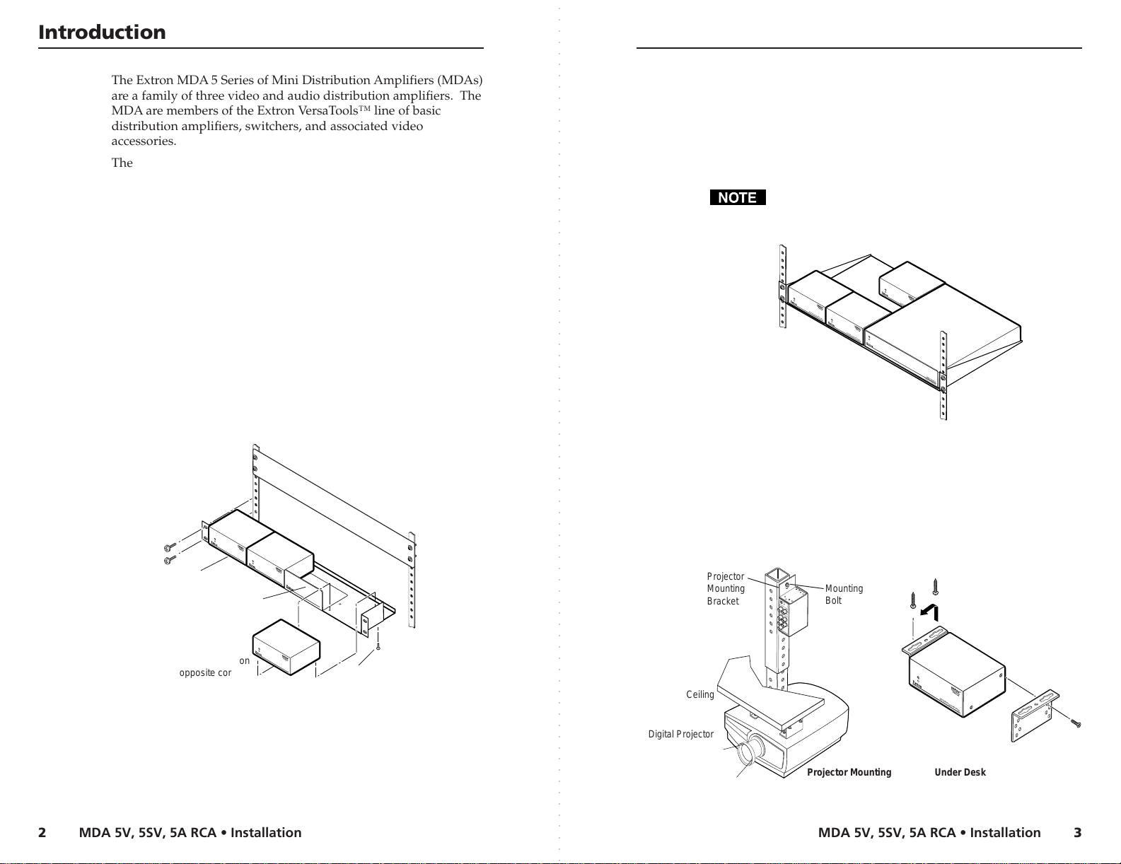
The MDA 5V, 5SV, and 5A RCA can be mounted on a rack shelf,
under a desk or tabletop, or on a projector bracket.
Rack mounting
For optional rack mounting, mount the MDA on a VersaTools 19"
1U Rack Shelf (Extron part #60-190-20) (figure 1) or a standard
Universal 1U Rack Shelf (Extron part #60-190-01) (figure 2). On
the standard rack shelf, the MDA mounts in one of four locations
to the rear of the rack or in one of four locations to the front of the
rack.
3. Install blank panel(s) or other unit(s) to the rack shelf.
4. Insert the shelf into the rack, aligning the holes in the shelf
with those of the rack.
5. Secure the shelf to the rack using the supplied machine
screws. This shelf can be mounted in the front or in the rear
of the rack.
Only products in the VersaTools line can be mounted to a
VersaTools shelf. Any 1U rack-mountable Extron product
can be mounted on the standard shelf.
Figure 2 — Mounting the MDA on the standard shelf
Furniture or projector mounting
Furniture mount or projector mount the MDA using the optional
mounting kit (Part #70-212-01, furniture, or 70-217-01, projector)
as follows:
1. Attach the mounting brackets to the MDA with the machine
screws provided (figure 3).
Figure 1 — Rack mounting the MDA 5V, 5SV, or 5A
RCA on the VersaTools shelf
1. If feet were previously installed on the bottom of the MDA,
2. Mount the MDA on the rack shelf, using two 4-40 x 3/16
remove them.
screws in opposite (diagonal) corners to secure the MDA to
the shelf.
Figure 3 — Desk and projector mounting the
MDA 5V, 5SV, or 5A RCA
MDA 5V, 5SV, 5A RCA • InstallationMDA 5V, 5SV, 5A RCA • Installation
○○○○○○○○○○○○○○○○○○○○○○○○○○○○○○○○○○○○○○○○○○○○○○○○○○○○○○○○○○○○○○○○○○○○○○○○○○○○○○○○○○○○○○○○○○○○○○○○○○○○○○○○○○○○○○○○○○○○○○○○○○○○○○○○○○○○○○○○○○○○○○○○○○○○○○○○○○○
32
Page 3

Installation
1
2
3
CAUTION
Return
+12V
End view of power
supply output cord.
Captive Screw
Connector
DISTRIBUTION AMPLIFIER
MDA 5SV
POWER
12V
.5A MAX
4
3
5
INPUT
IN
HIGH Z
75 Ohm
LOOP
2
1
OUTPUTS
5
2
1
6
MDA 5V
POWER
12V
.5A MAX
4
3
5
INPUT
IN
HIGH Z
75 Ohm
LOOP
2
1
OUTPUTS
1
2
3
5
6
MDA 5A RCA
POWER
12V
.34A MAX
INPUT
OUTPUTS
1
2
3
4
5
L
R
7
8
3
3
Front Panel
All Models
Rear Panel
MDA 5V
Rear Panel
MDA 5SV
Rear Panel
MDA 5A RCA
4
2. If feet were previously installed on the bottom of the MDA,
remove them.
3. For furniture mounting, hold the MDA with the attached
brackets against the underside of the table or other
furniture. Mark the location of the screw holes of the
bracket on the mounting surface.
4. For furniture mounting, drill 3/32” (2 mm) diameter pilot
holes, 1/4” (6.3 mm) deep in the mounting surface at the
marked screw locations.
5. For furniture mounting, insert #8 wood screws into the four
pilot holes. Tighten each screw into the mounting surface
until just less than 1/4” of the screw head protrudes.
6. For furniture mounting, align the mounting screws with
the slots in the brackets and place the MDA against the
surface, with the screws through the bracket slots.
7. For furniture mounting, slide the receiver slightly forward
or back, then tighten all four screws to secure the MDA in
place.
8. For projector mounting, secure the MDA to a projector
mount or other surface by inserting the mounting bolt
through the bracket’s slotted hole.
○○○○○○○○○○○○○○○○○○○○○○○○○○○○○○○○○○○○○○○○○○○○○○○○○○○○○○○○○○○○○○○○○○○○○○○○○○○○○○○○○○○○○○○○○○○○○○○○○○○○○○○○○○○○○○○○○○○○○○○○○○○○○○○○○○○○○○○○○○○○○○○○○○○○○○○○○○○
Figure 4 — Power connector wiring
Do not tin the stripped power supply leads before
installing the captive screw connector. Tinned wires are
not as secure in the captive screw connectors and could
pull out.
The two power cord wires must be kept separate
while the power supply is plugged in. Remove
power before continuing.
To verify the polarity before connection, plug in the power
supply with no load and check the output with a voltmeter.
Connections and Indicator
Refer to figure 5.
Video Input connector — (MDA 5V - composite video and
MDA 5SV - S-video) Connect an input to this connector.
Video Outputs (1 through 5) connectors — Connect up to
five video devices to these connectors. (MDA 5V composite video and MDA 5SV - S-video).
Power connector— Plug the external 12V power supply
into this 2-pole captive screw connector. The power supply
is included with the unit. Figure 4 shows how to wire the
connector.
When connecting the power supply, voltage polarity
is extremely important. Applying power with
incorrect voltage polarity could damage the power
supply and the MDA. Identify the power cord
negative lead by the ridges on the side of the cord.
Figure 5 — MDA 5V front and rear panels
MDA 5V, 5SV, 5A RCA • SpecificationsMDA 5V, 5SV, 5A RCA • Connections
54
Page 4

Specifications
123
CAUTION
4
5
6
7
8
Return
+12V
End view of power
supply output cord.
Captive Screw
Connector
DISTRIBUTION AMPLIFIER
MDA 5SV
POWER
12V
.5A MAX
4
3
5
INPUT
IN
HIGH Z
75 Ohm
LOOP
2
1
OUTPUTS
5
2
1
6
MDA 5V
POWER
12V
.5A MAX
4
3
5
INPUT
IN
HIGH Z
75 Ohm
LOOP
2
1
OUTPUTS
1
2
3
5
6
MDA 5A RCA
POWER
12V
.34A MAX
INPUT
OUTPUTS
1
2
3
4
5
L
R
7
8
3
3
Front Panel
All Models
Rear Panel
MDA 5V
Rear Panel
MDA 5SV
Rear Panel
MDA 5A RCA
4
Video
Gain ................................................... Unity
Bandwidth
Differential phase error .................. 0.05º, 0 to 50 MHz
Differential gain error .................... <0.05%, 0 to 50 MHz
Video input
Number/signal type
Connectors
Nominal levels ................................. Composite video and Y of S-video: 1V p-p
Minimum/maximum level(s)
Impedance ........................................ 75 ohms
Return loss ........................................ <-40dB @ 0 to 10 MHz for MDA 5V
Maximum DC offset ....................... 1.0V
Power LED — Indicates power is applied.
Loop connector — Provides passive loop-through for signal
High Z / 75 Ohm switch — Select 75-ohm termination on
or off.
High Z — Select this position (up) if you are
connecting a terminated device to the Loop connector.
75 Ohm — This position (down) terminates the Input
connector with 75 ohms of impedance. Select this
position if you are not using the Loop connector, or if
you are connecting an unterminated device to the
Loop connector.
Audio input (left and right) connectors — Connect
unbalanced stereo to this RCA connector
Audio output (1 through 5, left and right) connectors —
Connect up to five audio (stereo) devices to these RCA
connectors.
Specifications
MDA 5SV ............................. 270 MHz (-3dB)
MDA 5V ............................... 435 MHz (-3dB)
MDA 5SV ............................. 1 NTSC/PAL/SECAM S-video
MDA 5V ............................... 1 NTSC/PAL/SECAM composite video
MDA 5SV ............................. 1 4-pin mini DIN female
MDA 5V ............................... 1 BNC female
MDA 5SV ............................. Y: 0.4V to 2.0V p-p with no offset
MDA 5V ............................... 0.4V to 2.0V p-p with no offset
MDA 5V, 5SV, 5A RCA • Specifications
C of S-video: 0.3V p-p
<-25dB @ 0 to 10 MHz for MDA 5SV
Video output
Number/signal type
MDA 5SV ............................. 6 S-video: 5 buffered for distribution, 1
passive loop-through
MDA 5V ............................... 6 composite video: 5 buffered for
distribution, 1 passive loop-through
Connectors
MDA 5SV ............................. 6 4-pin mini-DIN
MDA 5V ............................... 6 BNC female
Nominal levels ................................. Composite video and Y of S-video: 1V p-p
C of S-video: 0.3V p-p
Minimum/maximum level(s) ....... 0.4V to 2.0V p-p
Impedance ........................................ 75 ohms
Return loss ........................................ -30dB @ 5 MHz
DC offset ........................................... ±5mV maximum with input at 0 offset
Sync
Standards .......................................... NTSC 3.58, NTSC 4.43, PAL, SECAM
Audio — MDA 5A RCA
Gain ................................................... Unity (0dB)
Frequency response ........................ 20 Hz to 20 kHz, ±0.05dB
THD + Noise .................................... 0.03% @ 1 kHz at nominal level
S/N .................................................... >90 dB, at rated maximum output drive
Stereo channel separation .............. >80 dB @ 1 kHz; >60 dB @ 20 kHz
CMRR ................................................ >75 dB @ 20 Hz to 20 kHz
Audio input — MDA 5A RCA
Number/signal type ...................... 1 stereo unbalanced
Connectors ....................................... 2 RCA connectors
Impedance ........................................ >10 kohms unbalanced, DC coupled
Nominal levels ................................. Compatible with -10dBV (316mV), +4dBu
(1.23V), 0dBu (0.775V), -20dBV (100mV)
Maximum level ............................... +18 dBu unbalanced at 1%THD+N
Audio output — MDA 5A RCA
Number/signal type ...................... 5 stereo, unbalanced
Connectors ....................................... 10 RCA connectors
Impedance ........................................ 50 ohms unbalanced
Gain error ......................................... ±0.1dB channel to channel
Nominal levels ................................. Compatible with -10dBV (316mV), +4dBu
(1.23V), 0dBu (0.775V), -20dBV (100mV)
Maximum level (Hi-Z) ................... >+18dBu, unbalanced at 1%THD+N
0dBu = 0.775 volts (RMS).
MDA 5V, 5SV, 5A RCA • Specifications
76
Page 5

User’s Guide
Extron Electronics, USA
1230 South Lewis Street
Anaheim, CA 92805
USA
714.491.1500
Fax 714.491.1517
Extron Electronics, Europe
Beeldschermweg 6C
3821 AH Amersfoort
The Netherlands
+31.33.453.4040
Fax +31.33.453.4050
Extron Electronics, Asia
135 Joo Seng Road, #04-01
PM Industrial Building
Singapore 368363
+65.6383.4400
Fax +65.6383.4664
Extron Electronics, Japan
Daisan DMJ Building 6F
3-9-1 Kudan Minami
Chiyoda-ku, Tokyo 102-0074 Japan
+81.3.3511.7655
Fax +81.3.3511.7656
www.extron.com
General
D
IS
T
RIB
UT
I
O
N
AM
P
LI
FIE
R
D
I
STR
IBU
T
ION
A
MP
LIF
IER
D
IS
TR
IB
UT
IO
N A
M
PL
IF
IER
M
DA S
ER
IES
DI
ST
RI
BU
TIO
N
AM
P
LIF
IE
R
DIS
TRIBU
TION
A
MP
LIFIER
Ceiling
Digital Projector
Projector
Mounting
Bracket
MDA 5V
PO
W
E
R
15V
.5A
MAX
1
2
3
4
IN
P
U
T
O
U
TP
U
T
S
Mounting
Bolt
Projector Mounting
Under Desk Mounting
(2) 4-40 x 3/16" screws
Use 2 mounting holes on
opposite corners
VersaTools Rack Shelf
1/4 Rack Width False Front
Face Plate
D
I
S
TR
I
B
U
T
ION
A
M
P
L
IF
I
E
R
D
I
S
T
R
I
B
U
T
IO
N
A
M
P
L
I
F
IE
R
D
IS
T
R
IB
U
T
IO
N
A
M
P
L
IF
I
E
R
Power ................................................ 100VAC to 240VAC, 50/60 Hz, 5 watts,
external, auto-switchable; to 12VDC,
1 A (max.) power supply. Product requires
0.4 A (max).
Temperature/humidity ................. Storage -40° to +158°F (-40° to +70°C) / 10%
to 90%, non-condensing
Operating +32° to +122°F (0° to +50°C) / 10%
to 90%, non-condensing
Rack mount ...................................... Yes, with optional 1U rack shelf, part #60-
190-01,
or the VersaTools rack shelf, part #60-190-20
Enclosure type ................................. Metal
Enclosure dimensions .................... 1.7" H x 4.3" W x 3.0" D (1U high, quarter
rack width)
4.2 cm H x 11.0 cm W x 7.6 cm D
(Depth excludes connectors and knobs.)
Product weight ................................ 0.7 lbs (0.3 kg)
Shipping weight .............................. 3 lbs (1.4 kg)
Vibration ........................................... ISTA/NSTA 1A in carton (International Safe
Transit Association)
Listings .............................................. UL, CUL
Compliances .................................... CE, FCC Class A, VCCI, AS/NZS, ICES
MTBF ................................................. 30,000 hours
Warranty ........................................... 3 years parts and labor
Specifications are subject to change without notice.
FCC Class A Notice
Note: This equipment has been tested and found to comply with the limits for a
Class A digital device, pursuant to part 15 of the FCC Rules. These limits are designed
to provide reasonable protection against harmful interference when the equipment is
operated in a commercial environment. This equipment generates, uses and can
radiate radio frequency energy and, if not installed and used in accordance with the
instruction manual, may cause harmful interference to radio communications.
Operation of this equipment in a residential area is likely to cause harmful
interference, in which case the user will be required to correct the interference at his
own expense.
Note: This unit was tested with shielded cables on the peripheral devices. Shielded
cables must be used with the unit to ensure compliance.
© 2002 Extron Electronics. All rights reserved.
 Loading...