

Page 1
User’s Manual
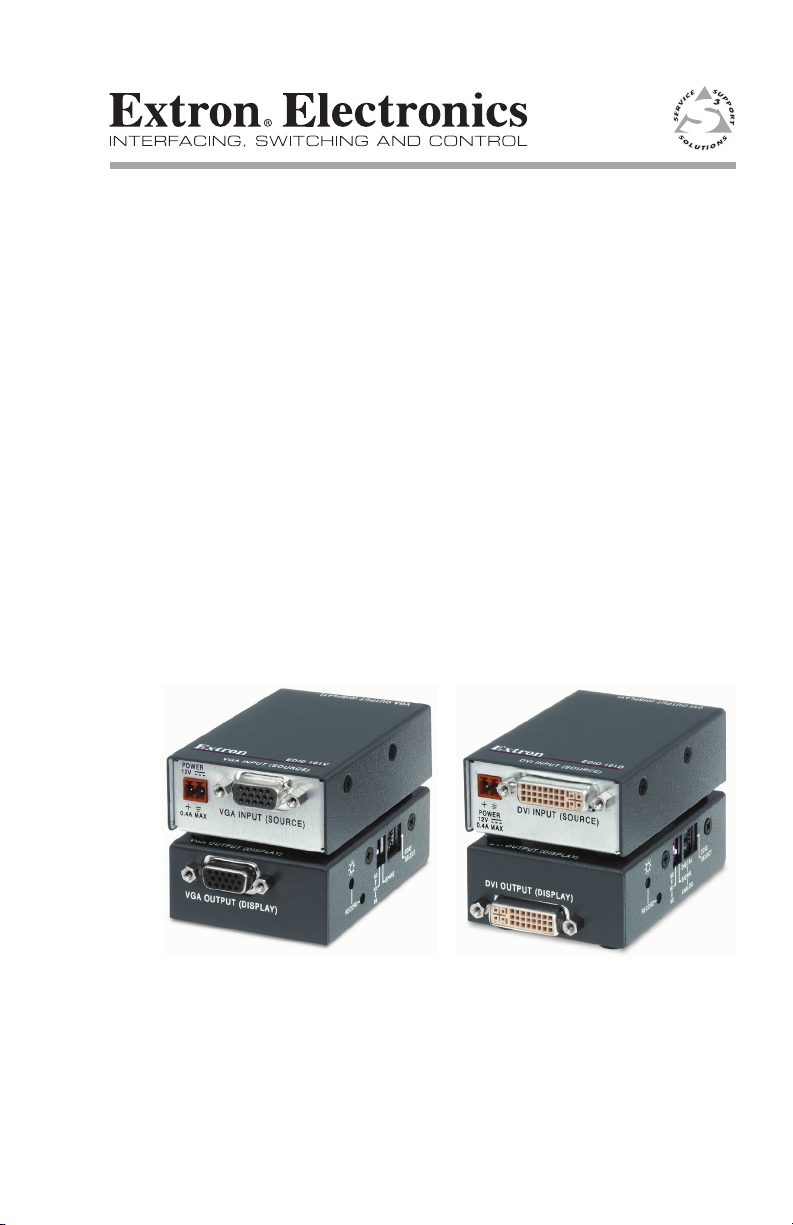
EDID 101D & EDID 101V
EDID Emulator with EDID Minder
68-1773-01
Rev. A
06 09
™
Page 2
Precautions
Safety Instructions • English
This symbol is intended to alert the user of important
operating and maintenance (servicing) instructions in
the literature provided with the equipment.
This symbol is intended to alert the user of the
presence of uninsulated dangerous voltage within
the product’s enclosure that may present a risk of
electric shock.
Caution
Read Instructions • Read and understand all safety and operating
instructions before using the equipment.
Retain Instructions • The safety instructions should be kept for future
reference.
Follow Warnings • Follow all warnings and instructions marked on the
equipment or in the user information.
Avoid Attachments • Do not use tools or attachments that are not
recommended by the equipment manufacturer because they may be
hazardous.
Consignes de Sécurité • Français
Ce s ymbole s ert à a vertir l’ut ilisateu r que l a
documentation fournie avec le matériel contient des
instructions importantes concernant l’exploitation et
la maintenance (réparation).
Ce symbole sert à avertir l’utilisateur de la présence
dans le boîtier de l’appareil de tensions dangereuses
non isolées posant des risques d’électrocution.
Attention
Lire les instructions• Prendre connaissance de toutes les consignes de
sécurité et d’exploitation avant d’utiliser le matériel.
Conserver les instructions• Ranger les consignes de sécurité afin de pouvoir
les consulter à l’avenir.
Respecter les avertissements • Observer tous les avertissements et consignes
marqués sur le matériel ou présentés dans la documentation utilisateur.
Eviter les pièces de xation • Ne pas utiliser de pièces de fixation ni d’outils
non recommandés par le fabricant du matériel car cela risquerait de poser
certains dangers.
Sicherheitsanleitungen • Deutsch
Dies es Sym bol so ll dem Benut zer in der i m
Li efe rum fan g en tha lte nen D oku men tat ion
besonders wichtige Hinweise zur Bedienung und
Wartung (Instandhaltung) geben.
Dieses Symbol soll den Benutzer darauf aufmerksam
machen , daß im I nneren des Gehäuses diese s
Produktes gefährliche Spannungen, die nicht isoliert
sind und die einen elektrischen Schock verursachen
können, herrschen.
Achtung
Lesen der Anleitungen • Bevor Sie das Gerät zum ersten Mal verwenden,
sollten Sie alle Sicherheits-und Bedienungsanleitungen genau durchlesen
und verstehen.
Aufbewahren der Anleitungen • Die Hinweise zur elektrischen Sicherheit
des Produktes sollten Sie aufbewahren, damit Sie im Bedarfsfall darauf
zurückgreifen können.
Befolgen der Warnhinweise • Befolgen Sie alle Warnhinweise und
Anleitungen auf dem Gerät oder in der Benutzerdokumentation.
Keine Zusatzgeräte • Verwenden Sie keine Werkzeuge oder Zusatzgeräte,
die nicht ausdrücklich vom Hersteller empfohlen wurden, da diese eine
Gefahrenquelle darstellen können.
Instrucciones de seguridad • Español
Este símbolo se util iza para advertir al usuario
sobre instruc ciones importantes de operación y
mantenimiento (o cambio de partes) que se desean
destac ar en el c ontenido de la docume ntación
suministrada con los equipos.
Este símbolo se utiliza para advertir al usuario sobre
la presencia de elementos con voltaje peligroso sin
protección aislante, que puedan encontrarse dentro
de la caja o alojamiento del producto, y que puedan
representar riesgo de electrocución.
Precaucion
Leer las instrucciones • Leer y analizar todas las instrucciones de operación y
seguridad, antes de usar el equipo.
Conservar las instrucciones • Conservar las instrucciones de seguridad para
futura consulta.
Obedecer las advertencias • Todas las advertencias e instrucciones marcadas
en el equipo o en la documentación del usuario, deben ser obedecidas.
Evitar el uso de accesorios • No usar herramientas o accesorios que no
sean especificamente recomendados por el fabricante, ya que podrian
implicar riesgos.
Warning
Power sources • This equipment should be operated only from the power source
indicated on the product. This equipment is intended to be used with a main power
system with a grounded (neutral) conductor. The third (grounding) pin is a safety
feature, do not attempt to bypass or disable it.
Power disconnection • To remove power from the equipment safely, remove all power
cords from the rear of the equipment, or the desktop power module (if detachable),
or from the power source receptacle (wall plug).
Power cord protection • Power cords should be routed so that they are not likely to be
stepped on or pinched by items placed upon or against them.
Servicing • Refer all servicing to qualified service personnel. There are no user-
serviceable parts inside. To prevent the risk of shock, do not attempt to service
this equipment yourself because opening or removing covers may expose you to
dangerous voltage or other hazards.
Slots and openings • If the equipment has slots or holes in the enclosure, these are
provided to prevent overheating of sensitive components inside. These openings
must never be blocked by other objects.
Lithium battery • There is a danger of explosion if battery is incorrectly
replaced. Replace it only with the same or equivalent type recommended by
the manufacturer. Dispose of used batteries according to the manufacturer’s
instructions.
Avertissement
Alimentations• Ne faire fonctionner ce matériel qu’avec la source d’alimentation
indiquée sur l’appareil. Ce matériel doit être utilisé avec une alimentation principale
comportant un fil de terre (neutre). Le troisième contact (de mise à la terre) constitue
un dispositif de sécurité : n’essayez pas de la contourner ni de la désactiver.
Déconnexion de l’alimentation• Pour mettre le matériel hors tension sans danger,
déconnectez tous les cordons d’alimentation de l’arrière de l’appareil ou du module
d’alimentation de bureau (s’il est amovible) ou encore de la prise secteur.
Protection du cordon d’alimentation • Acheminer les cordons d’alimentation de
manière à ce que personne ne risque de marcher dessus et à ce qu’ils ne soient pas
écrasés ou pincés par des objets.
Réparation-maintenance • Faire exécuter toutes les interventions de réparation-
maintenance par un technicien qualifié. Aucun des éléments internes ne peut être
réparé par l’utilisateur. Afin d’éviter tout danger d’électrocution, l’utilisateur ne doit
pas essayer de procéder lui-même à ces opérations car l’ouverture ou le retrait des
couvercles risquent de l’exposer à de hautes tensions et autres dangers.
Fentes et orices • Si le boîtier de l’appareil comporte des fentes ou des orifices, ceux-ci
servent à empêcher les composants internes sensibles de surchauffer. Ces ouvertures
ne doivent jamais être bloquées par des objets.
Lithium Batterie • Il a danger d’explosion s’ll y a remplacment incorrect de la batterie.
Remplacer uniquement avec une batterie du meme type ou d’un ype equivalent
recommande par le constructeur. Mettre au reut les batteries usagees conformement
aux instructions du fabricant.
Vorsicht
Stromquellen • Dieses Gerät sollte nur über die auf dem Produkt angegebene
Stromquelle betrieben werden. Dieses Gerät wurde für eine Verwendung mit einer
Hauptstromleitung mit einem geerdeten (neutralen) Leiter konzipiert. Der dritte
Kontakt ist für einen Erdanschluß, und stellt eine Sicherheitsfunktion dar. Diese
sollte nicht umgangen oder außer Betrieb gesetzt werden.
Stromunterbrechung • Um das Gerät auf sichere Weise vom Netz zu trennen, sollten
Sie alle Netzkabel aus der Rückseite des Gerätes, aus der externen Stomversorgung
(falls dies möglich ist) oder aus der Wandsteckdose ziehen.
Schutz des Netzkabels • Netzkabel sollten stets so verlegt werden, daß sie nicht im
Weg liegen und niemand darauf treten kann oder Objekte darauf- oder unmittelbar
dagegengestellt werden können.
Wartung • Alle Wartungsmaßnahmen sollten nur von qualiziertem Servicepersonal
durchgeführt werden. Die internen Komponenten des Gerätes sind wartungsfrei.
Zur Vermeidung eines elektrischen Schocks versuchen Sie in keinem Fall, dieses
Gerät selbst öffnen, da beim Entfernen der Abdeckungen die Gefahr eines
elektrischen Schlags und/oder andere Gefahren bestehen.
Schlitze und Öffnungen • Wenn das Gerät Schlitze oder Löcher im Gehäuse aufweist,
dienen diese zur Vermeidung einer Überhitzung der empndlichen Teile im
Inneren. Diese Öffnungen dürfen niemals von anderen Objekten blockiert werden.
Litium-Batterie • Explosionsgefahr, falls die Batterie nicht richtig ersetzt
wird. Ersetzen Sie verbrauchte Batterien nur durch den gleichen oder einen
vergleichbaren Batterietyp, der auch vom Hersteller empfohlen wird. Entsorgen Sie
verbrauchte Batterien bitte gemäß den Herstelleranweisungen.
Advertencia
Alimentación eléctrica • Este equipo debe conectarse únicamente a la fuente/tipo
de alimentación eléctrica indicada en el mismo. La alimentación eléctrica de este
equipo debe provenir de un sistema de distribución general con conductor neutro
a tierra. La tercera pata (puesta a tierra) es una medida de seguridad, no puentearia
ni eliminaria.
Desconexión de alimentación eléctrica • Para desconectar con seguridad la acometida
de alimentación eléctrica al equipo, desenchufar todos los cables de alimentación
en el panel trasero del equipo, o desenchufar el módulo de alimentación (si fuera
independiente), o desenchufar el cable del receptáculo de la pared.
Protección del cables de alimentación • Los cables de alimentación eléctrica se deben
instalar en lugares donde no sean pisados ni apretados por objetos que se puedan
apoyar sobre ellos.
Reparaciones/mantenimiento • Solicitar siempre los servicios técnicos de personal
calificado. En el interior no hay partes a las que el usuario deba acceder. Para evitar
riesgo de electrocución, no intentar personalmente la reparación/mantenimiento
de este equipo, ya que al abrir o extraer las tapas puede quedar expuesto a voltajes
peligrosos u otros riesgos.
Ranuras y aberturas • Si el equipo posee ranuras o orificios en su caja/alojamiento,
es para evitar el sobrecalientamiento de componentes internos sensibles. Estas
aberturas nunca se deben obstruir con otros objetos.
Batería de litio • Existe riesgo de explosión si esta batería se coloca en la posición
incorrecta. Cambiar esta batería únicamente con el mismo tipo (o su equivalente)
recomendado por el fabricante. Desachar las baterías usadas siguiendo las
instrucciones del fabricante.
Page 3

安全须知 • 中文
这个符号提示用户该设备用户手册中
有重要的操作和维护说明。
这个符号警告用户该设备机壳内有暴
露的危险电压,有触电危险。
注意
阅读说明书 • 用户使用该设备前必须阅读并理
解所有安全和使用说明。
保存说明书 • 用户应保存安全说明书以备将来使
用。
遵守警告 • 用户应遵守产品和用户指南上的所有安
全和操作说明。
避免追加 • 不要使用该产品厂商没有推荐的工具或
追加设备,以避免危险。
警告
电源 • 该设备只能使用产品上标明的电源。 设备
必须使用有地线的供电系统供电。 第三条线
(地线)是安全设施,不能不用或跳过。
拔掉电源 • 为安全地从设备拔掉电源,请拔掉所有设备后
或桌面电源的电源线,或任何接到市电系统的电源线。
电源线保护 • 妥善布线, 避免被踩踏,或重物挤压。
维护 • 所有维修必须由认证的维修人员进行。 设备内部
没有用户可以更换的零件。为避免出现触电危险不要自
己试图打开设备盖子维修该设备。
通风孔 • 有些设备机壳上有通风槽或孔,它们是用来防止
机内敏感元件过热。 不要用任何东西挡住通风孔。
锂电池 • 不正确的更换电池会有爆炸的危险。 必须使用
与厂家推荐的相同或相近型号的电池。 按照生产厂的
建议处理废弃电池。
声明
所使用电源为 A 级产品,在生活环境中,该产品可能会造成无线电干扰。在这种情况下,可能需要用
户对其干扰采取切实可行的措施。
FCC Class A Notice
This equipment has been tested and found to comply with the limits for a Class A digital device,
pursuant to part 15 of the FCC Rules. Operation is subject to the following two conditions: (1) this
device may not cause harmful interference, and (2) this device must accept any interference received,
including interference that may cause undesired operation. The Class A limits are designed to
provide reasonable protection against harmful interference when the equipment is operated in
a commercial environment. This equipment generates, uses, and can radiate radio frequency
energy and, if not installed and used in accordance with the instruction manual, may cause harmful
interference to radio communications. Operation of this equipment in a residential area is likely to
cause harmful interference, in which case the user will be required to correct the interference at his
own expense.
N
This unit was tested with shielded cables on the peripheral devices. Shielded cables must be used
with the unit to ensure compliance with FCC emissions limits.
VCCI Class A notice for ITE products
この装置は、クラスA 情報技術装置です。 この装置を家庭環境で使用すると電波妨害を引き起こ
すことがあります。 この場合には使用者が適切な対策 を講ずるよう要求されることがあります。
VCCI-A
English translation: “This is a Class A product. In a domestic environment this product may cause radio
interference, in which case the user may be required to take corrective actions.”
Equipment labeled VCCI-A satisfies the limits of interference for Class A.
N
Page 4

Table of Contents
About this Manual ....................................................................... 1
About the EDID 101 ..................................................................... 1
EDID 101 Features ......................................................................... 2
Mounting the EDID 101 .............................................................. 5
Tabletop placement .................................................................. 5
Rack mounting .......................................................................... 5
UL guidelines for rack mounting ..............................................5
Rack mounting procedures .......................................................6
Furniture mounting .................................................................. 7
Panel Features................................................................................ 8
Side panel .................................................................................. 8
Front and rear panels ............................................................... 9
EDID 101D/EDID 101V Operation .......................................... 10
Recording a display EDID ....................................................... 10
Using the pre-programmed Extron EDID ............................. 11
Specications ............................................................................... 12
Included Parts .............................................................................. 14
Accessories .................................................................................... 14
All trademarks mentioned in this manual are the properties of their respective owners.
68-1773-01 Rev. A
EDID 101D/EDID 101V • Table of Contents
06 09
iii
Page 5

About this Manual
This manual contains information about the Extron
EDID 101D/EDID 101V, with instructions on how to mount and
operate the unit. Throughout this manual EDID 101 is used to
refer to the EDID 101D and EDID 101V. Where differences may
occur, they are noted.
About the EDID 101
The EDID 101D and EDID 101V are compact, economical
EDID Minder™ devices that record and manage display EDID
(Extended Display Identication Data). A source device
normally uses EDID to identify the signal type (i.e. analog or
digital), the native rate of the display, how to correctly output
the preferred native timing, additional rates supported by the
display, and various other information.
The Extron EDID 101 is a standalone EDID Minder device that
emulates EDID to a DVI or VGA source. It helps ensure the
video source boots up correctly and constantly outputs video.
The EDID 101 records the EDID from a display and supplies it to
the video source. In addition, there are pre-programmed EDIDs
matched with two refresh rates (50 and 60 Hz) and two signal
types (digital and analog).
EDID 101D/EDID 101V • Introduction
1
Page 6

Introduction
EDID 101 Features
EDID Minder — Enables continuous EDID communication
to the input source. EDID provides information about
a display identity. The EDID Minder continuous EDID
communication helps ensure the source boots up properly
and reliably outputs content to the display.
EDID Record — Enables the device to record EDID directly
from a display.
Pre-programmed EDID — The EDID 101 contains
pre-programmed EDIDs with the most common display
native resolutions for both 50 and 60 Hz. Along with the
native rate, each pre-programmed EDID also lists other
common video rates for use by the video source.
N
Powered from the video source — The EDID 101 is powered
Power LED — The side panel LED illuminates green when
Compact size — Small form factor enables use in places where
Configuring the EDID 101 rotary and DIP switches
from a VGA or DVI video source for normal operation.
An optional external 12 VDC power supply for remote
learning capability is also available.
power is connected and ashes red during EDID
recording.
space is a premium.
allow a user to select a pre-programmed EDID based on
the native rate of a display (i.e. 1280x1024 @ 60 Hz)
and a desired signal type (i.e. digital), but does not
necessarily force a video source to output that rate. Since
EDID is not limited to reporting a single video rate
(i.e. the native rate), each Extron EDID also lists other
common video rates for use by the video source.
2
EDID 101D/EDID 101V • Introduction
Page 7

DVI DA2
COMPUTER IN
AUDIO IN
DVI DA2
DVI DISTRIBUTION AMPLIFIER
DVI INPUT (SOURCE)
DVI OUTPUT (DISPLAY)
D-SUB NPUT (SOURCE)
D-SUB OUTPUT (DISPLAY)
DVI-DVI
Mac-Mini
DVI-DVI
DVI-DVI
EDID 101D
Projector
EDID 101D
EDID to PC
(No EDID Passed)
EDID 101V
PC
VGA-VGA
Twisted Pair
VGA-VGA
VGA-VGA
Projector
EDID 101V
MTP 15 HD A D
MTP RL 15 HD RS
RGB
PEAKING
LEVEL
MTP SERIES
Typical EDID 101 applications
EDID 101D/EDID 101V • Introduction
3
Page 8

Introduction, cont’d
IN1508
DVI INPUT (SOURCE)
DVI OUTPUT (DISPLAY)
DV I-DV I
Mac-Mini
DVI-DVI
EDID 101D
VGA-BNC
Projector
EDID 101D
INPUT OUTPUT RATE PIP
SCALING PRESENTATION SWITCHER
IR
IN1508
PICTURE CONTROL
VGA
SVGA
XGA
SXGA
ON7654321 SWAP8CENTER SIZE
CONT/
BRT
COL/
TNT
MENU ENTER
1024x852
1024x1024
1366x768
1365x1024
UXGA
720p
1080i
1080p
RS232
AUDIO
INPUTS
AUDIO
OUTPUTS
L
R
L
R
L
R
1
2
1
3
4
2
1.5A MAX
R
1
2
G
B
H
V
R
G
B
H
V
INPUTS
OUTPUTS
R
G
B
H
V
100-240V 50-60Hz
3
4
1
2
H
V
H
V
H
V
H
V
1
ON
2
3
4
Projector
Extron
Crosspoint 300 42 HVA
Wideband Matrix Switcher
Laptop
Flat Panel
Display
Extron
EDID 101V
EDID Minder
Extron
EDID 101V
EDID Minder
PC
VGA OUTPUT (DISPLAY)
VGA OUTPUT (DISPLAY)
VGA INPUT (SOURCE)
EDID 101D
VGA OUTPUT (DISPLAY)
VGA INPUT (SOURCE)
EDID 101D
VGA OUTPUT (DISPLAY)
4
EDID 101D/EDID 101V • Introduction
Typical EDID 101 applications
Page 9

Mounting the EDID 101
The EDID 101 is housed in a 1/8 rack width, 3" deep, 1" high
metal enclosure. The small form factor is ideal for connecting
the EDID 101 between two devices that would otherwise be
directly connected.
N
Tabletop placement
Rack mounting
After the EDID 101 is mounted, the side panel may be
inconvenient or impossible to access for configuration. To
avoid uninstalling, program it prior to mounting.
See page 10, "EDID 101D/EDID 101V Operation" for
programming details.
Attach the four included rubber feet to the bottom of the unit
and place it in any convenient location.
UL guidelines for rack mounting
The following Underwriters Laboratories (UL) guidelines are
relevant to the safe installation of the EDID 101 in a rack:
1. Elevated operating ambient temperature — If the unit
is installed in a closed or multi-unit rack assembly, the
operating ambient temperature of the rack environment
may be greater than room ambient temperature. Therefore,
install the equipment in an environment compatible with
the maximum ambient temperature (Tma: +122 °F, +50 ° C)
specied by Extron.
2. Reduced air flow — Install the equipment in the rack so
the equipment gets adequate air ow for safe operation.
3. Mechanical loading — Mount the equipment in the rack
so that uneven mechanical loading does not create a
hazardous condition.
4. Circuit overloading — Connect the equipment to
the supply circuit and consider the effect that circuit
overloading might have on overcurrent protection and
supply wiring. Give appropriate consideration to the
equipment nameplate ratings.
5. Reliable earthing (grounding) — Maintain reliable
grounding of rack-mounted equipment. Pay particular
attention to supply connections other than direct
connections to the branch circuit (such as power strips).
EDID 101D/EDID 101V • Installation and Operation
5
Page 10
Installation and Operation, cont’d
EighthRackVersaToolsShelf
(2) 4-40 x 3/16"
Screws
Use 2 mounting holes on
opposite corners.
1/4 Rack Width Front
False Faceplate
Rack mounting procedures
The unit can be mounted in the front or rear of any of these rack
systems:
RSF 123 rack shelf kit for 3.5" deep products •
(part #60-190-20)
RSB 123 basic rack shelf kit for 3.5" deep products •
(part #60-604-20)
RSU 126 universal rack shelf kit for 6" deep products •
(part #60-190-10)
RSB 126 basic rack shelf kit for 6" deep products •
(part #60-604-10)
RSU 129 universal rack shelf kit for 9.5" deep products •
(part #60-190-01)
RSB 129 basic rack shelf kit for 9.5" deep products •
(part #60-604-01)
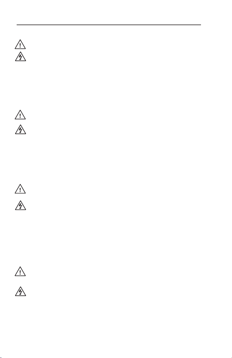
To rack mount the EDID 101D/EDID 101V:
1. If necessary, remove the rubber feet.
2. Secure the EDID 101 to the shelf with two 4-40 x 3/16"
screws in opposite corners of the base (see below).
3. Install false faceplate(s) or other unit(s) to the rack shelf.
4. Attach the shelf to the rack with the four provided
10-32 x 3/4" bolts.
Rack mounting the EDID 101
6
EDID 101D/EDID 101V • Installation and Operation
Page 11

Furniture mounting
The EDID 101 can be mounted under furniture using optional
mounting kit MBU 125 (part #70-077-01) as follows:
1. Attach the mounting brackets to the EDID 101 with the
provided machine screws as shown in the gure below.
2. Hold the EDID 101 with the attached brackets against the
underside of the table or other furniture. Mark the location
of the screw holes in the brackets on the mounting surface.
3. Drill 3/32" (2.4 mm) diameter pilot holes, 1/4" (6.3 mm)
deep in the mounting surface at the marked screw locations.
4. Insert #8 wood screws into the four pilot holes. Tighten each
screw into the mounting surface until just less than 1/4" of
the screw head protrudes.
5. Align the mounting screws with the slots in the brackets and
place the EDID 101 and brackets against the surface, with the
screws through the bracket slots.
6. Slide the EDID 101 slightly forward or back, then tighten all
four screws to secure the unit in place.
Mounting the EDID 101 under a desk
N
When mounting the EDID 101 under a desk using an
MBU 125, the EDID configuration switches located
on the side of the product will no longer be accessible.
Ensure the EDID 101 is configured prior to mounting.
See page 10, "EDID 101D/EDID 101V Operation" for
programming details.
EDID 101D/EDID 101V • Installation and Operation
7
Page 12
Installation and Operation, cont’d
DVI OUTPUT (DISPLAY)
DVI INPUT (SOURCE)
POWER
12V
0.4A MAX
EDID
SELECT
60
Hz
50
RECORD
DIGITAL
SIGNAL
ANALOG
ON
12
VGA OUTPUT (DISPLAY)
CONFIG
VGA INPUT (SOURCE)
POWER
12V
0.4A MAX
EDID
SELECT
60
Hz
50
RECORD
SPARE
ON
12
EDID 101D
EDID 101V
g a b c d e f
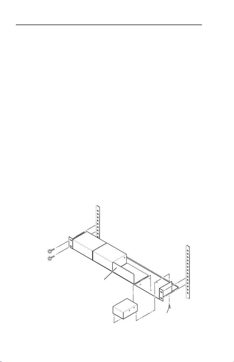
Panel Features
EDID 101 Panel views
Side panel
Power LED — Dual-color multi-purpose LED:
a
Green — Indicates power is connected from the 5 VDC pin
of a DVI/VGA video source or by the optional 12 VDC
power supply (
Flashing red — During the recording process, indicates a new
EDID being written to memory, returning to solid green
when the write completes.
e
).
Record button — This recessed button is used to
b
initiate recording of a connected display device EDID to
user-programmable memory (position 0 on the rotary switch).
DIP switch — Position 1 is used to select the vertical refresh
c
frequency for the pre-programmed EDID. When switched to
"Off", the EDID selected by rotary positions 1 through F are
based on 50 Hz. When switched to "On", they are based on
60 Hz (default position).
Position 2, (not used on EDID 101V; labeled "Spare"), selects the
signal format, digital or analog, for the pre-programmed EDID.
EDID Rotary Switch — Position 0 of this 16 position rotary
d
switch is used to record an EDID from a display.
Positions 1-F select pre-programmed EDID resolutions.
N
Configuring the EDID 101 rotary and DIP switches
allow a user to select a pre-programmed EDID based on
the native rate of a display (i.e. 1280x1024 @ 60 Hz)
and a desired signal type (i.e. digital), but does not
necessarily force a video source to output that rate. Since
EDID is not limited to reporting a single video rate
(i.e. the native rate), each Extron EDID also lists other
8
EDID 101D/EDID 101V • Installation and Operation
common video rates for use by the video source.
Page 13

Front and rear panels
Power connector — An optional external 12 VDC power
e
supply may be connected to this 2-pole, 3.5 mm captive screw
connector.
N
Input connector — EDID 101D – Female DVI-I.
f
EDID 101V – Female D-Sub 15 pin.
Output connector — EDID 101D – Female DVI-I.
g
EDID 101V – Female D-Sub 15 pin.
N
During normal operation the EDID 101 is powered
using +5 VDC from pin 9 of a DDC compliant VGA
source (EDID 101V) or pin 14 of a DVI source
(EDID 101D).
If the source is capable of providing power for the
EDID 101, the green Power LED (
the source is connected and powered on.
When the EDID 101 is powered from a video source,
there is no need to connect an external power supply.
DVI-A to VGA adapters may be used to connect the
EDID 101D to analog displays and sources having VGA
connectors. EDID functionality, if the VGA source
supports it, will remain available.
) will light when
a
N
EDID 101D/EDID 101V • Installation and Operation
The EDID 101 is a pass-through device and should be
located as close to the input source as possible.
The total length of DVI cabling, including input and
output cables, connected to the EDID 101D should not
exceed maximum recommended lengths for standard
DVI applications.
9
Page 14

Installation and Operation, cont’d
EDID 101D/EDID 101V Operation
The EDID 101 can either record EDID from a display device or a
pre-programmed EDID can be selected using the rotary and DIP
switches.
Recording a display EDID
To record a new EDID into memory:
Turn the rotary switch (1.
N
N
N
N
N
The DIP switch positions have no effect in this mode.
Apply power to the EDID 101 by connecting a power 2.
source.
If power is not available from a video source, an external
12 VDC power supply can be used. The green LED will
be lit when power is available.
Connect the display device to the 3. OUTPUT of the
EDID 101 using a DVI (EDID 101D) or a VGA (EDID 101V)
cable.
To capture analog EDID on the EDID 101D, a DVI-A to
VGA adapter must be used.
Power on the display device.4.
Although the EDID 101 supplies 5 VDC to power the
EDID circuitry of a display device, power on the display
device to ensure that data is being transmitted during
the recording process.
Press and hold the recessed record button (5.
LED ashes red rapidly, then release the button. The LED
continues to ash red, then returns to solid green when
the EDID data has been stored. The display can now be
disconnected.
If an external supply was used for recording, it can now
be disconnected.
Install the EDID 101 into the system. 6.
) to position 0.
d
) until the
b
10
EDID 101D/EDID 101V • Installation and Operation
Page 15

4
6
7
8
9
A
B
5
3
2
1
0
F
E
D
C
1 2
ON
60
Hz
50
DIGITAL
SIGNAL
ANALOG
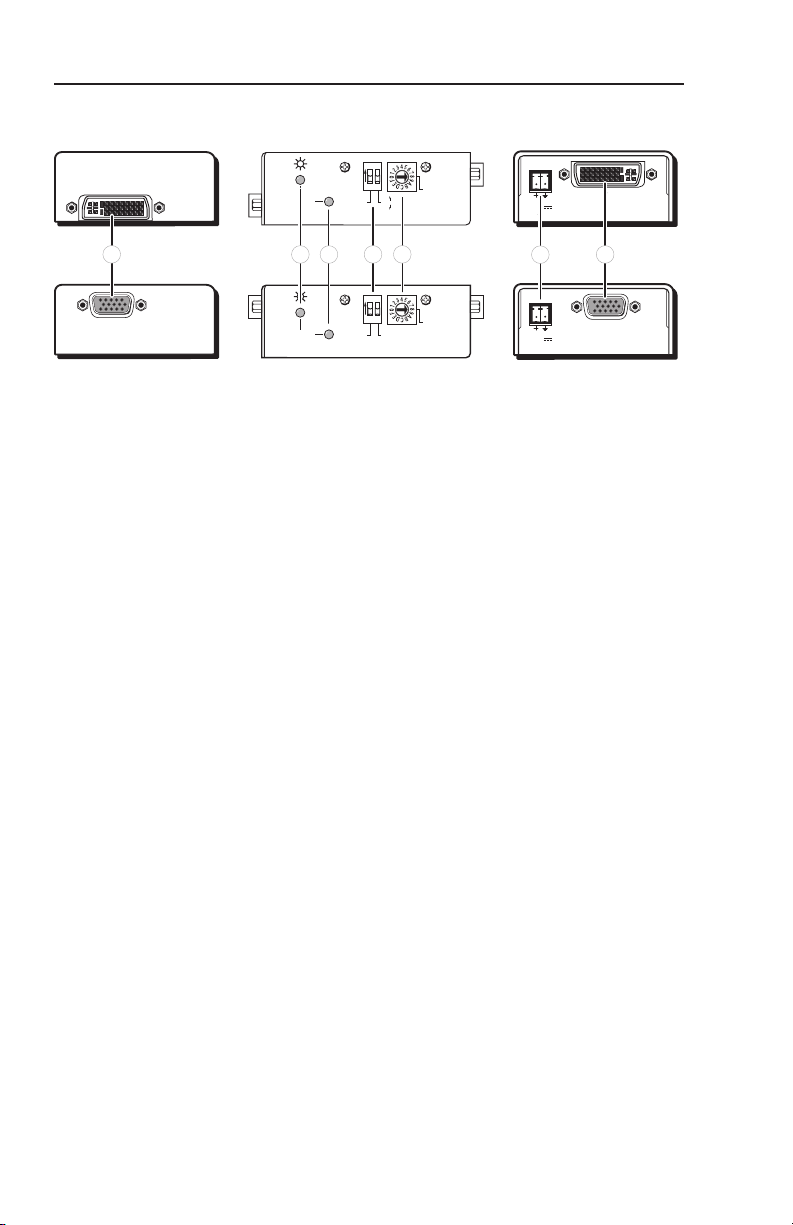
Using the pre-programmed Extron EDID
N
Configuring the EDID 101 rotary and DIP switches allow
a user to select a pre-programmed EDID based on the native
rate of a display (i.e. 1280x1024 @ 60 Hz) and a desired
signal type (i.e. digital), but does not necessarily force a video
source to output that rate.
Since EDID is not limited to reporting a single video rate
(i.e. the native rate), each Extron EDID also lists other
common video rates for use by the video source.
Choose a resolution from Table 1 based on the native resolution 1.
of the display. Note the corresponding rotary switch position.
To use the EDID, set the rotary switch (2.
position (1-F) selected in step 1. The switch clicks as
it moves through the positions.
) to the
d
Rotary Switch
Position
Resolution
0 User Recorded EDID
1 800x600
2 1024x768
3 1280x720
4 1280x768
5 1280x800
6 1280x1024
7 1360x768
8 1366x768
9 1400x1050
A 1440x900
B 1600x1200
C 1680x1050
D 1920x1080
E 1920x1200
F
Digital: Dual Link DVI
Analog: Not Used
Table 1 — Rotary Switch position
N
When using a dual link DVI display with the EDID 101D
(position F), only two resolutions will be shown to the video
source, 1280x800 and 2560x1600.
Set the rst DIP switch (3.
) based on the
c
vertical refresh of the native rate of the display.
(default is ON, 60 Hz).
For the EDID 101D only, choose digital or 4.
analog based on the input signal format.
Install the EDID 101 into the system. 5.
EDID 101D/EDID 101V • Installation and Operation
11
Page 16

Reference Material
Specifications
N
If you use a DVI-A to 15-pin HD adapter, the EDID 101D can
be used for analog signal pass-through.
Video — EDID 101D, digital signals
Maximum data rate....................... 10 Gbps (3.3 Gbps per color)
Maximum pixel clock ................... 330 MHz (165 MHz per link)
Resolution range ........................... Up to 2560x1600 @ 60 Hz
Formats ........................................... RGB and YCbCr digital video
Standards ........................................ DVI 1.0, EDID 1.3
Video input — EDID 101D, digital signals
Number/signal type ..................... 1 dual or single link DVI-D
Connectors ..................................... 1 female DVI-I
Video output — EDID 101D, digital signals
Number/signal type ..................... 1 dual or single link DVI-D
Connectors ..................................... 1 female DVI-I
Video — EDID 101D, analog signals; EDID 101V
Bandwidth ...................................... 350 MHz (-3dB)
Gain ................................................. Unity
Video input— EDID 101D, analog signals; EDID 101V
Number/signal type ..................... 1 analog VGA-UXGA RGBHV, RGBS,
RGsB, RsGsBs
Connector ....................................... 1 female 15-pin HD
Nominal level ................................ 0.7 Vp-p for RGB
Minimum/maximum levels ........ Analog: 0.3 V to 1.5 Vp-p with no offset
Impedance ...................................... 75 ohms
Horizontal frequency .................... 15 kHz to 145 kHz
Vertical frequency .......................... 30 Hz to 170 Hz
Video output— EDID 101D, analog signals; EDID 101V
Number/signal type ..................... 1 analog RGBHV, RGBS, RGsB,RsGsBs
(follows input)
Connector ....................................... 1 female 15-pin HD
Minimum/maximum levels ........ Follows input
Impedance ...................................... 75 ohms
12
EDID 101D/EDID 101V • Reference Material
Page 17

General
Power .............................................. Supplied by the 5 V signal from a DVI
source (pin 14), a VGA* source (pin 9), or
from an external power supply
N
External power supply ................. 100 VAC to 240 VAC, 50-60 Hz, external; to
Power input requirements ........... 12 VDC, 0.05 A
Temperature/humidity ................ Storage: -40 to +158 °F (-40 to +70 °C) /
Cooling ........................................... Convection, no vents
Mounting
Enclosure type ............................... Metal
Enclosure dimensions ................... 1.0" H x 2.2" W x 3.0" D (one-eighth rack
Product weight .............................. 0.4 lbs (0.2 kg)
Shipping weight ............................ 2 lbs (1 kg)
Vibration ......................................... ISTA 1A in carton (International Safe
Regulatory compliance
MTBF ............................................... 30,000 hours
Warranty ......................................... 3 years parts and labor
*Some VGA source devices do not provide power output.
12 VDC, 1 A, regulated
10% to 90%, noncondensing
Operating: +32 to +122 °F (0 to +50 °C) /
10% to 90%, noncondensing
Rack mount ........................ Yes, with optional 1U rack shelf
wide)
(2.5 cm H x 5.6 cm W x 7.6 cm D)
Transit Association)
Safety ................................... CE, c-UL, UL
EMI/EMC .......................... CE, C-tick, FCC Class A, ICES,
VCCI Class A
Environmental ................... Complies with the appropriate
requirements of RoHS, WEEE
N
N
All nominal levels are at ±10%.
Specifications are subject to change without notice.
EDID 101D/EDID 101V • Reference Material
13
Page 18

Reference Material, cont’d
Included Parts
These items are included in each order for an EDID 101:
Included parts Replacement
EDID 101D
-or- EDID 101V
(4) Rubber feet (unattached)
(2) Strips of Velcro (unattached)
EDID 101D/EDID 101V Setup Guide
Accessories
Accessories Part number
PS 1210C 12 VDC, 1 A power supply 70-775-01
RSU 129, universal rack shelf kit for 9.5"
deep products (gray)
RSB 129, basic rack shelf kit for 9.5" deep
products, black, gray
RSU 126, universal rack shelf kit for
6" deep products
RSB 126, basic rack shelf kit for 6" deep
products
RSF 123, rack shelf kit for 3.5" deep
products (with faceplates)
RSB 123, basic rack shelf kit for 3.5" deep
products, black, gray
MBB 100, Back of the Rack mounting kit 70-367-01
MBU 125, Under-desk mounting kit 70-077-01
part number
60-990-01
60-991-01
60-190-01
60-604-01, -02
60-190-10
60-604-11
60-190-20
60-604-20, -21
14
EDID 101D/EDID 101V • Reference Material
Page 19

Extron Warranty
Extron Electronics warrants this product against defects in materials and
workmanship for a period of three years from the date of purchase. In the event of
malfunction during the warranty period attributable directly to faulty workmanship
and/or materials, Extron Electronics will, at its option, repair or replace said products
or components, to whatever extent it shall deem necessary to restore said product to
proper operating condition, provided that it is returned within the warranty period,
with proof of purchase and description of malfunction to:
USA, Canada, South America,
and Central America:
Extron Electronics
1001 East Ball Road
Anaheim, CA 92805
U.S.A.
Europe, Africa, and the Middle East:
Extron Europe
Hanzeboulevard 10
3825 PH Amersfoort
The Netherlands
Asia:
Extron Asia
135 Joo Seng Road, #04-01
PM Industrial Bldg.
Singapore 368363
Singapore
This Limited Warranty does not apply if the fault has been caused by misuse,
improper handling care, electrical or mechanical abuse, abnormal operating
conditions or non-Extron authorized modification to the product.
If it has been determined that the product is defective, please call Extron and ask for
an Applications Engineer at (714) 491-1500 (USA), 31.33.453.4040 (Europe), 65.383.4400
(Asia), or 81.3.3511.7655 (Japan) to receive an RA# (Return Authorization number).
This will begin the repair process as quickly as possible.
Units must be returned insured, with shipping charges prepaid. If not insured, you
assume the risk of loss or damage during shipment. Returned units must include the
serial number and a description of the problem, as well as the name of the person to
contact in case there are any questions.
Extron Electronics makes no further warranties either expressed or implied with
respect to the product and its quality, performance, merchantability, or fitness for
any particular use. In no event will Extron Electronics be liable for direct, indirect,
or consequential damages resulting from any defect in this product even if Extron
Electronics has been advised of such damage.
Please note that laws vary from state to state and country to country, and that some
provisions of this warranty may not apply to you.
Japan:
Extron Electronics, Japan
Kyodo Building, 16 Ichibancho
Chiyoda-ku, Tokyo 102-0082
Japan
China:
Extron China
686 Ronghua Road
Songjiang District
Shanghai 201611
China
Middle East:
Extron Middle East
Dubai Airport Free Zone
F12, PO Box 293666
United Arab Emirates, Dubai
Page 20

Extron USA - West
Headquarters
+800.633.9876
Inside USA / Canada Only
+1.714.491.1500
+1.714.491.1517 FAX
Extron USA - East
+800.633.9876
Inside USA / Canada Only
+1.919.863.1794
+1.919.863.1797 FAX
Extron Europe
+800.3987.6673
Inside Europe Only
+31.33.453.4040
+31.33.453.4050 FA X
Extron Asia
+800.7339.8766
Inside Asia Only
+65.6383.4400
+65.6383.4664 FAX
Extron Japan
+81.3.3511.7655
+81.3.3511.7656 FAX
Extron China
+400.883.1568
Inside China Only
+86.21.3760.1568
+86.21.3760.1566 FAX
Extron Middle East
+971.4.2991800
+971.4.2991880 FAX
© 2009 Extron Electronics. All rights reserved.
 Loading...